- Table of Contents
-
- 03-Layer 2—LAN Switching Configuration Examples
- 01-M-LAG Configuration Examples
- 02-MAC Address Table Configuration Examples
- 03-MVRP Configuration Examples
- 04-S-MLAG Configuration Examples
- 05-VLAN Configuration Examples
- 06-Ethernet Link Aggregation Configuration Examples
- 07-VLAN Tagging Configuration Examples
- 08-Spanning Tree Configuration Examples
- 09-Port Isolation Configuration Examples
- Related Documents
-
| Title | Size | Download |
|---|---|---|
| 06-Ethernet Link Aggregation Configuration Examples | 269.16 KB |
Example: Configuring Layer 2 link aggregation
Applicable hardware and software versions
Example: Configuring Layer 2 link aggregation load sharing
Applicable hardware and software versions
Example: Configuring Layer 2 Ethernet link aggregation with IRF
Applicable hardware and software versions
Example: Configuring Layer 3 link aggregation
Applicable hardware and software versions
Example: Configuring Layer 3 link aggregation load sharing
Applicable hardware and software versions
Introduction
This document provides Ethernet link aggregation configuration examples.
Prerequisites
The configuration examples in this document were created and verified in a lab environment, and all the devices were started with the factory default configuration. When you are working on a live network, make sure you understand the potential impact of every command on your network.
This document assumes that you have basic knowledge of Ethernet link aggregation.
Example: Configuring Layer 2 link aggregation
Network configuration
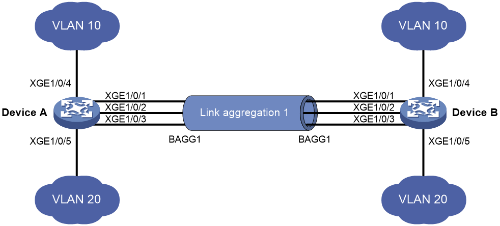
As shown in Figure 1, both Device A and Device B forward traffic from VLAN 10 and VLAN 20.
Configure link aggregation on Device A and Device B to meet the following requirements:
· VLAN 10 on Device A can communicate with VLAN 10 on Device B.
· VLAN 20 on Device A can communicate with VLAN 20 on Device B.
Analysis
To enable traffic from VLAN 10 and VLAN 20 to pass through Layer 2 aggregate interface Bridge-aggregation 1, perform the following tasks:
· Configure Layer 2 aggregate interface Bridge-aggregation 1 as a trunk port.
· Assign the aggregate interface to VLAN 10 and VLAN 20.
Applicable hardware and software versions
The following matrix shows the hardware and software versions to which this configuration example is applicable:
|
Hardware |
Software version |
|
S12500G-AF switch series |
Release 7639P01 and later |
|
S10500X switch series |
Release 7639P01 and later |
|
S10500 switch series |
Release 7639P01 and later |
|
S7500E-X switch series |
Release 7639P01 and later |
|
S7500E switch series |
Release 7639P01 and later |
|
S7500X switch series |
Release 7639P01 and later |
Restrictions and guidelines
When you configure Layer 2 link aggregation, follow these restrictions and guidelines:
· When you assign a port to an aggregation group, the recommended configuration procedure is as follows:
a. Use the display this command in interface view to check the following attribute configurations of the port:
- Port isolation.
- QinQ.
- VLAN.
- VLAN mapping.
b. If any of the above configurations exist, use the undo forms of the corresponding commands to remove these configurations. This enables the port to use the default attribute configurations.
c. Assign the port to the aggregation group.
· In a static aggregation group, the Selected state of a port is not affected by whether the peer port is added to an aggregation group and is Selected. As a result, the Selected state of a port might be different from the Selected state of the peer port. When both ends support static aggregation and dynamic aggregation, use dynamic aggregation.
· You cannot assign a port to a Layer 2 aggregation group when MAC authentication, port security mode, or 802.1X is configured or enabled on the port.
Procedures
1. Configure Device A:
# Create VLAN 10, and assign port Ten-GigabitEthernet 1/0/4 to VLAN 10.
<DeviceA> system-view
[DeviceA] vlan 10
[DeviceA-vlan10] port ten-gigabitethernet 1/0/4
[DeviceA-vlan10] quit
# Create VLAN 20, and assign port Ten-GigabitEthernet 1/0/5 to VLAN 20.
[DeviceA] vlan 20
[DeviceA-vlan20] port ten-gigabitethernet 1/0/5
[DeviceA-vlan20] quit
# Create Layer 2 aggregate interface Bridge-aggregation 1. Use one of the following methods as needed.
¡ Use the static aggregation mode to create Layer 2 aggregate interface Bridge-aggregation 1.
[DeviceA] interface bridge-aggregation 1
[DeviceA-Bridge-Aggregation1] undo shutdown
[DeviceA-Bridge-Aggregation1] quit
¡ Use the dynamic aggregation mode to create Layer 2 aggregate interface Bridge-aggregation 1.
[DeviceA] interface bridge-aggregation 1
[DeviceA-Bridge-Aggregation1] link-aggregation mode dynamic
[DeviceA-Bridge-Aggregation1] undo shutdown
[DeviceA-Bridge-Aggregation1] quit
# Assign ports Ten-GigabitEthernet 1/0/1 through Ten-GigabitEthernet 1/0/3 to aggregation group 1.
[DeviceA] interface range ten-gigabitethernet 1/0/1 to ten-gigabitethernet 1/0/3
[DeviceA-if-range] port link-aggregation group 1
[DeviceA-if-range] undo shutdown
[DeviceA-if-range] quit
# Configure Layer 2 aggregate interface Bridge-aggregation 1 as a trunk port.
[DeviceA] interface bridge-aggregation 1
[DeviceA-Bridge-Aggregation1] port link-type trunk
Configuring Ten-GigabitEthernet1/0/1 done.
Configuring Ten-GigabitEthernet1/0/2 done.
Configuring Ten-GigabitEthernet1/0/3 done.
# Assign the aggregate interface to VLANs 10 and 20.
[DeviceA-Bridge-Aggregation1] port trunk permit vlan 10 20
Configuring Ten-GigabitEthernet1/0/1 done.
Configuring Ten-GigabitEthernet1/0/2 done.
Configuring Ten-GigabitEthernet1/0/3 done.
[DeviceA-Bridge-Aggregation1] quit
2. Configure Device B in the same way Device A is configured. (Details not shown.)
Verifying the configuration
# Display detailed information about the link aggregation groups on Device A.
· Link aggregation configuration information when the static aggregation mode is used:
[DeviceA] display link-aggregation verbose
Loadsharing Type: Shar -- Loadsharing, NonS -- Non-Loadsharing
Port Status: S -- Selected, U -- Unselected, I -- Individual
Port: A -- Auto port, M -- Management port, R -- Reference port
Flags: A -- LACP_Activity, B -- LACP_Timeout, C -- Aggregation,
D -- Synchronization, E -- Collecting, F -- Distributing,
G -- Defaulted, H -- Expired
Aggregation Interface: Bridge-Aggregation1
Aggregation Mode: Static
Loadsharing Type: Shar
Management VLANs: None
Port Status Priority Oper-Key
XGE1/0/1(R) S 32768 1
XGE1/0/2 S 32768 1
XGE1/0/3 S 32768 1
The output shows that all member ports in the local aggregation group are in the Selected state. The Selected states of the local member ports are not affected by the Selected states of the peer member ports.
· Link aggregation configuration information when the dynamic aggregation mode is used:
[DeviceA] display link-aggregation verbose
Loadsharing Type: Shar -- Loadsharing, NonS -- Non-Loadsharing
Port Status: S -- Selected, U -- Unselected, I -- Individual
Port: A -- Auto port, M -- Management port, R -- Reference port
Flags: A -- LACP_Activity, B -- LACP_Timeout, C -- Aggregation,
D -- Synchronization, E -- Collecting, F -- Distributing,
G -- Defaulted, H -- Expired
Aggregation Interface: Bridge-Aggregation1
Creation Mode: Manual
Aggregation Mode: Dynamic
Loadsharing Type: Shar
Management VLANs: None
System ID: 0x8000, 000f-e234-5678
Local:
Port Status Priority Index Oper-Key Flag
XGE1/0/1 S 32768 2 1 {ACDEF}
XGE1/0/2 S 32768 3 1 {ACDEF}
XGE1/0/3 S 32768 4 1 {ACDEF}
Remote:
Actor Priority Index Oper-Key SystemID Flag
XGE1/0/1(R) 32768 2 1 0x8000, a4e5-c316-0100 {ACDEF}
XGE1/0/2 32768 3 1 0x8000, a4e5-c316-0100 {ACDEF}
XGE1/0/3 32768 4 1 0x8000, a4e5-c316-0100 {ACDEF}
The output shows that the local member ports and the corresponding peer member ports are all Selected. In the dynamic link aggregation mode, each local member port and its peer member port have the same Selected state through exchanging LACPDUs. The user data traffic can be forwarded correctly.
Configuration files
· Device A:
#
vlan 10
#
interface Ten-GigabitEthernet1/0/4
port link-mode bridge
port access vlan 10
#
vlan 20
#
interface Ten-GigabitEthernet1/0/5
port link-mode bridge
port access vlan 20
¡ In the static aggregation mode:
#
interface Bridge-Aggregation1
port link-type trunk
port trunk permit vlan 10 20
¡ In the dynamic aggregation mode:
#
interface Bridge-Aggregation1
port link-type trunk
port trunk permit vlan 10 20
link-aggregation mode dynamic
#
interface Ten-GigabitEthernet1/0/1
port link-mode bridge
port link-type trunk
port trunk permit vlan 10 20
port link-aggregation group 1
#
interface Ten-GigabitEthernet1/0/2
port link-mode bridge
port link-type trunk
port trunk permit vlan 10 20
port link-aggregation group 1
#
interface Ten-GigabitEthernet1/0/3
port link-mode bridge
port link-type trunk
port trunk permit vlan 10 20
port link-aggregation group 1
#
· Device B:
The configuration file on Device B is the same as the configuration file on Device A.
Example: Configuring Layer 2 link aggregation load sharing
Network configuration
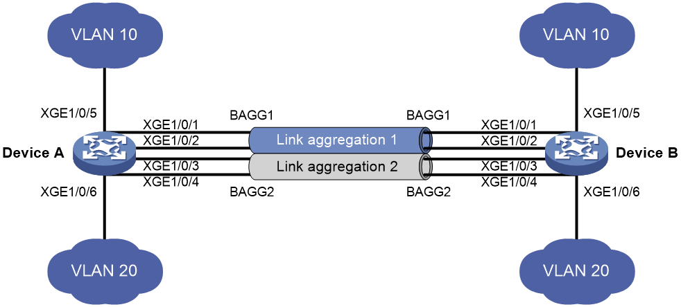
As shown in Figure 2, both Device A and Device B forward traffic from VLAN 10 and VLAN 20.
Configure link aggregation on Device A and Device B to meet the following requirements:
· VLAN 10 on Device A can communicate with VLAN 10 on Device B. VLAN 20 on Device A can communicate with VLAN 20 on Device B.
· The packets from VLAN 10 are load shared across the Selected ports of link aggregation group 1 by source MAC addresses. The packets from VLAN 20 are load shared across the Selected ports of link aggregation group 1 by destination MAC addresses.
Analysis
For different aggregation groups to process packets in different load sharing modes, configure the aggregation load sharing mode in Layer 2 aggregate interface view.
To enable packets from VLAN 10 to pass through aggregate interface Bridge-aggregation 1, assign the aggregate interface to VLAN 10. To enable packets from VLAN 20 to pass through aggregate interface Bridge-aggregation 2, assign the aggregate interface to VLAN 20.
Applicable hardware and software versions
The following matrix shows the hardware and software versions to which this configuration example is applicable:
|
Hardware |
Software version |
|
S12500G-AF switch series |
Release 7639P01 and later |
|
S10500X switch series |
Release 7639P01 and later |
|
S10500 switch series |
Release 7639P01 and later |
|
S7500E-X switch series |
Release 7639P01 and later |
|
S7500E switch series |
Release 7639P01 and later |
|
S7500X switch series |
Release 7639P01 and later |
Restrictions and guidelines
When you configure Layer 2 load sharing, follow these restrictions and guidelines:
· When you assign a port to an aggregation group, the recommended configuration procedure is as follows:
a. Use the display this command in interface view to check the following attribute configurations of the port:
- Port isolation.
- QinQ.
- VLAN.
- VLAN mapping.
b. If any of the above configurations exist, use the undo forms of the corresponding commands to remove these configurations. This enables the port to use the default attribute configurations.
c. Assign the port to the aggregation group.
· You cannot assign a port to a Layer 2 aggregation group when MAC authentication, port security mode, or 802.1X is configured or enabled on the port.
Procedures
1. Configure Device A:
# Create VLAN 10, and assign port Ten-GigabitEthernet 1/0/5 to VLAN 10.
<DeviceA> system-view
[DeviceA] vlan 10
[DeviceA-vlan10] port ten-gigabitethernet 1/0/5
[DeviceA-vlan10] quit
# Create VLAN 20, and assign port Ten-GigabitEthernet 1/0/6 to VLAN 20.
[DeviceA] vlan 20
[DeviceA-vlan20] port ten-gigabitethernet 1/0/6
[DeviceA-vlan20] quit
# Create Layer 2 aggregate interface 1, and configure Layer 2 aggregation group 1 to load-share packets based on source MAC addresses.
[DeviceA] interface bridge-aggregation 1
[DeviceA-Bridge-Aggregation1] link-aggregation load-sharing mode source-mac
[DeviceA-Bridge-Aggregation1] quit
# Assign ports Ten-GigabitEthernet 1/0/1 and Ten-GigabitEthernet 1/0/2 to aggregation group 1.
[DeviceA] interface ten-gigabitethernet 1/0/1
[DeviceA-Ten-GigabitEthernet1/0/1] port link-aggregation group 1
[DeviceA-Ten-GigabitEthernet1/0/1] quit
[DeviceA] interface ten-gigabitethernet 1/0/2
[DeviceA-Ten-GigabitEthernet1/0/2] port link-aggregation group 1
[DeviceA-Ten-GigabitEthernet1/0/2] quit
# Assign Layer 2 aggregate interface Bridge-aggregation 1 to VLAN 10.
[DeviceA] interface bridge-aggregation 1
[DeviceA-Bridge-Aggregation1] port access vlan 10
Configuring Ten-GigabitEthernet1/0/1 done.
Configuring Ten-GigabitEthernet1/0/2 done.
[DeviceA-Bridge-Aggregation1] quit
# Create Layer 2 aggregate interface 2, and configure Layer 2 aggregation group 2 to load-share packets based on destination MAC addresses.
[DeviceA] interface bridge-aggregation 2
[DeviceA-Bridge-Aggregation2] link-aggregation load-sharing mode destination-mac
[DeviceA-Bridge-Aggregation2] quit
# Assign ports Ten-GigabitEthernet 1/0/3 and Ten-GigabitEthernet 1/0/4 to aggregation group 2.
[DeviceA] interface ten-gigabitethernet 1/0/3
[DeviceA-Ten-GigabitEthernet1/0/3] port link-aggregation group 2
[DeviceA-Ten-GigabitEthernet1/0/3] quit
[DeviceA] interface ten-gigabitethernet 1/0/4
[DeviceA-Ten-GigabitEthernet1/0/4] port link-aggregation group 2
[DeviceA-Ten-GigabitEthernet1/0/4] quit
# Assign Layer 2 aggregate interface Bridge-aggregation 2 to VLAN 20.
[DeviceA] interface bridge-aggregation 2
[DeviceA-Bridge-Aggregation2] port access vlan 20
Configuring Ten-GigabitEthernet1/0/3 done.
Configuring Ten-GigabitEthernet1/0/4 done.
[DeviceA-Bridge-Aggregation2] quit
2. Configure Device B in the same way Device A is configured. (Details not shown.)
Verifying the configuration
# Display the information about Selected ports in link aggregation groups on Device A.
[DeviceA] display link-aggregation verbose
Loadsharing Type: Shar -- Loadsharing, NonS -- Non-Loadsharing
Port Status: S -- Selected, U -- Unselected , I -- Individual
Port: A -- Auto port, M -- Management port, R -- Reference port
Flags: A -- LACP_Activity, B -- LACP_Timeout, C -- Aggregation,
D -- Synchronization, E -- Collecting, F -- Distributing,
G -- Defaulted, H -- Expired
Aggregation Interface: Bridge-Aggregation1
Aggregation Mode: Static
Loadsharing Type: Shar
Management VLANs: None
Port Status Priority Oper-Key
XGE1/0/1(R) S 32768 1
XGE1/0/2 S 32768 1
Aggregation Interface: Bridge-Aggregation2
Aggregation Mode: Static
Loadsharing Type: Shar
Management VLANs: None
Port Status Priority Oper-Key
XGE1/0/3(R) S 32768 2
XGE1/0/4 S 32768 2
The output shows the following information:
· Link aggregation groups 1 and 2 are both Layer 2 static aggregation groups.
· Each aggregation group has two Selected ports for forwarding traffic.
# Display the link aggregation load sharing mode.
[DeviceA]display link-aggregation load-sharing mode interface Bridge-Aggregation 1
Bridge-Aggregation1 load-sharing mode:
source-mac address
[DeviceA]display link-aggregation load-sharing mode interface Bridge-Aggregation 2
Bridge-Aggregation2 load-sharing mode:
destination-mac address
The output shows that Bridge-aggregation 1 uses the source MAC addresses for load sharing, and Bridge-aggregation 2 uses the destination MAC addresses for load sharing.
Configuration files
· Device A:
#
vlan 10
#
interface Ten-GigabitEthernet1/0/5
port link-mode bridge
port access vlan 10
#
vlan 20
#
interface Ten-GigabitEthernet1/0/6
port link-mode bridge
port access vlan 10
#
interface Bridge-Aggregation1
port access vlan 10
link-aggregation load-sharing mode source-mac
#
interface Ten-GigabitEthernet1/0/1
port link-mode bridge
port access vlan 10
port link-aggregation group 1
#
interface Ten-GigabitEthernet1/0/2
port link-mode bridge
port access vlan 10
port link-aggregation group 1
#
interface Bridge-Aggregation2
port access vlan 20
link-aggregation load-sharing mode destination-mac
#
interface Ten-GigabitEthernet1/0/3
port link-mode bridge
port access vlan 20
port link-aggregation group 2
#
interface Ten-GigabitEthernet1/0/4
port link-mode bridge
port access vlan 20
port link-aggregation group 2
#
link-aggregation global load-sharing mode source-mac
· Device B:
The configuration file on Device B is the same as the configuration file on Device A.
Example: Configuring Layer 2 Ethernet link aggregation with IRF
Network configuration
As shown in Figure 3, two devices exist at both the access layer and the distribution layer separately. Configure link aggregation and IRF to meet the following requirements:
Due to the continuous increase in company staff, the access layer must be easy to manage and have strong expansion capabilities to provide more ports to meet PC access requirements.
Due to increased traffic at the access layer, enhance reliability for the links from the access layer to the distribution layer and enable load sharing.

Analysis
To enhance the manageability and expansion capabilities of the access layer, configure IRF, which enables you to easily expand the number of ports and bandwidth at the access layer.
To enhance link reliability, configure link aggregation in conjunction with IRF. Connect each access layer device to the distribution layer with two uplinks and aggregate the four uplinks. If an IRF member device leaves the IRF fabric, the links on the other member device can still send and receive packets, thus increasing link reliability.
Configure link aggregation with load sharing to evenly distribute traffic during traffic forwarding.
Enable LACP MAD on both the distribution layer IRF fabric and the access layer IRF fabric, allowing the two IRF fabrics to act as intermediate device for each other and perform their own LACP MAD. In this way, the system can quickly identify the cause of an IRF split and promptly restore the IRF state of the member devices.
Applicable hardware and software versions
Table 1 Applicable hardware and software versions
|
Hardware |
Software version |
|
S12500G-AF switch series |
Release 7639P01 and later |
|
S10500X switch series |
Release 7639P01 and later |
|
S10500 switch series |
Release 7639P01 and later |
|
S7500E-X switch series |
Release 7639P01 and later |
|
S7500E switch series |
Release 7639P01 and later |
|
S7500X switch series |
Release 7639P01 and later |
Restrictions and guidelines
· To bind IRF physical interfaces to an IRF port, make sure they operate in Layer 2 mode.
· Multiple IRF physical interfaces bound to the same IRF port must operate in the same mode.
· In an IRF fabric, IRF physical interfaces connecting IRF member devices must be configured to operate in the same mode. For more information about configuring the operating mode for IRF physical interfaces, see IRF Configuration Guide.
· When you assign a port to an aggregation group, the recommended configuration procedure is as follows:
a. Use the display this command in interface view to check the following attribute configurations of the port:
- Port isolation.
- QinQ.
- VLAN.
- VLAN mapping.
b. If any of the preceding configurations exist, use the undo forms of the corresponding commands to remove these configurations. This enables the port to use the default attribute configurations.
c. Assign the port to the aggregation group.
· In a static aggregation group, the Selected state of a port is not affected by whether the peer port is assigned to an aggregation group and is Selected. As a result, the Selected state of a port might be different from the Selected state of the peer port. Additionally, LACP MAD must be applied to dynamic aggregate interfaces to take effect. Therefore, you must configure dynamic aggregation groups in this example.
· Ports with the following features configured or enabled cannot be assigned to a Layer 2 aggregation group: MAC authentication, port security mode, and 802.1X.
Procedures
1. Configure IRF settings for Device A:
# Shut down Ten-GigabitEthernet 1/1/0/1. For more information about IRF configuration, see IRF Configuration Guide.
<DeviceA> system-view
[DeviceA] interface ten-gigabitethernet 1/1/0/1
[DeviceA-Ten-GigabitEthernet1/1/0/1] shutdown
[DeviceA-Ten-GigabitEthernet1/1/0/1] quit
# Configure IRF port 1/1 and bind it to physical interface Ten-GigabitEthernet 1/1/0/1.
[DeviceA] irf-port 1/1
[DeviceA-irf-port1/1] port group interface ten-gigabitethernet 1/1/0/1
You must perform the following tasks for a successful IRF setup:
Save the configuration after completing IRF configuration.
Execute the "irf-port-configuration active" command to activate the IRF ports.
[DeviceA-irf-port1/1] quit
# Bring up Ten-GigabitEthernet 1/1/0/1 and save the configuration.
[DeviceA] interface ten-gigabitethernet 1/1/0/1
[DeviceA-Ten-GigabitEthernet1/1/0/1] undo shutdown
[DeviceA-Ten-GigabitEthernet1/1/0/1] quit
[DeviceA] save
# Activate the IRF port settings on the device.
[DeviceA] irf-port-configuration active
2. Configure IRF settings for Device B:
# Assign member ID 2 to Device B, and then reboot the device to have the new member ID take effect.
<DeviceB> system-view
[DeviceB] irf member 1 renumber 2
Renumbering the member ID may result in configuration change or loss. Continue? [Y/N]:y
[DeviceB] quit
<DeviceB> reboot
# Bind IRF physical interfaces to an IRF port as you do that on Device A. Take Ten-GigabitEthernet 2/1/0/1 as an example and shut down this port. For more information about IRF configuration, see IRF Configuration Guide.
<DeviceB> system-view
[DeviceB] interface ten-gigabitethernet 2/1/0/1
[DeviceB-Ten-GigabitEthernet2/1/0/1] shutdown
[DeviceB-Ten-GigabitEthernet2/1/0/1] quit
# Configure IRF port 2/2 and bind it to physical interface Ten-GigabitEthernet 2/1/0/1.
[DeviceB] irf-port 2/2
[DeviceB-irf-port2/2] port group interface ten-gigabitethernet 2/1/0/1
You must perform the following tasks for a successful IRF setup:
Save the configuration after completing IRF configuration.
Execute the "irf-port-configuration active" command to activate the IRF ports.
[DeviceB-irf-port2/2] quit
# Bring up Ten-GigabitEthernet 2/1/0/1 and save the configuration.
[DeviceB] interface ten-gigabitethernet 2/1/0/1
[DeviceB-Ten-GigabitEthernet2/1/0/1] undo shutdown
[DeviceB-Ten-GigabitEthernet2/1/0/1] quit
[DeviceB] save
# Activate the IRF port settings on the device.
[DeviceB] irf-port-configuration active
# Device A and Device B perform master election. The device that fails master election will reboot to form an IRF fabric with the other device.
# Use the display irf command to display IRF-related information. Device A is the master device.
[DeviceA] display irf
MemberID Role Priority CPU-Mac Description
*+1 Master 1 00a0-fc00-5801 ---
2 Standby 1 00e0-fc58-1235 ---
--------------------------------------------------
* indicates the device is the master.
+ indicates the device through which the user logs in.
The bridge MAC of the IRF is: 00a0-fc00-5800
Auto upgrade : yes
Mac persistent : 6 min
Domain ID : 0
Auto merge : yes
3. Configure the Layer 2 dynamic aggregation group for Device A:
# Create Layer 2 dynamic aggregate interface 1, and configure Layer 2 aggregation group 1 to load-share packets based on source IP addresses.
[DeviceA] interface bridge-aggregation 1
[DeviceA-Bridge-Aggregation1] link-aggregation mode dynamic
[DeviceA-Bridge-Aggregation1] link-aggregation load-sharing mode source-ip
[DeviceA-Bridge-Aggregation1] quit
# Assign Ten-GigabitEthernet 1/1/0/9, Ten-GigabitEthernet 1/1/0/10, Ten-GigabitEthernet 2/1/0/9, and Ten-GigabitEthernet 2/1/0/10 to the aggregation group.
[DeviceA] interface range ten-gigabitethernet 1/1/0/9 to ten-gigabitethernet 1/1/0/10
ten-gigabitethernet 2/1/0/9 to ten-gigabitethernet 2/1/0/10
[DeviceA-if-range] port link-aggregation group 1
[DeviceA-if-range] quit
4. Configure LACP MAD settings for Device A:
# Assign domain ID 1 to the IRF fabric.
# Enable LACP MAD on dynamic aggregation group 1.
[DeviceA] interface Bridge-Aggregation 1
[DeviceA-Bridge-Aggregation1] mad enable
You need to assign a domain ID (range: 0-4294967295)
[Current domain is: 1]:
The assigned domain ID is: 1
MAD LACP only enable on dynamic aggregation interface.
5. Configure IRF settings for Device C.
# Configure IRF settings on Device C in the same way Device A is configured. (Details not shown.)
6. Configure IRF settings for Device D.
# Configure IRF settings on Device D in the same way Device B is configured. (Details not shown.)
# Device C and Device D perform master election. The device that fails master election will reboot to form an IRF fabric with the other device.
7. Configure the Layer 2 dynamic aggregation group for Device C.
# Configure Layer 2 dynamic aggregation group settings on Device C in the same way Device A is configured. (Details not shown.)
8. Configure LACP MAD settings for Device C:
# Assign domain ID 2 to the IRF fabric.
<DeviceC> system-view
[DeviceC] irf domain 2
# Enable LACP MAD on dynamic aggregation group 1.
[DeviceC] interface Bridge-Aggregation 1
[DeviceC-Bridge-Aggregation1] mad enable
You need to assign a domain ID (range: 0-4294967295)
[Current domain is: 2]:
The assigned domain ID is: 2
MAD LACP only enable on dynamic aggregation interface.
Verifying the configuration
# On Device A, execute the display link-aggregation verbose command to display related information of aggregation groups.
[DeviceA] display link-aggregation verbose
Loadsharing Type: Shar -- Loadsharing, NonS -- Non-Loadsharing
Port Status: S -- Selected, U -- Unselected, I -- Individual
Port: A -- Auto port, M -- Management port, R -- Reference port
Flags: A -- LACP_Activity, B -- LACP_Timeout, C -- Aggregation,
D -- Synchronization, E -- Collecting, F -- Distributing,
G -- Defaulted, H -- Expired
Aggregate Interface: Bridge-Aggregation1
Creation Mode: Manual
Aggregation Mode: Dynamic
Loadsharing Type: Shar
Management VLANs: None
System ID: 0x8000, 00a0-fc00-5800
Local:
Port Status Priority Index Oper-Key Flag
XGE1/1/0/9(R) S 32768 10 1 {ACG}
XGE1/1/0/10 S 32768 11 1 {ACG}
XGE2/1/0/9 S 32768 138 1 {ACG}
XGE2/1/0/10 S 32768 139 1 {ACG}
Remote:
Actor Priority Index Oper-Key SystemID Flag
XGE1/1/0/9 32768 0 0 0x8000, 0000-0000-0000 {EF}
XGE1/1/0/10 32768 0 0 0x8000, 0000-0000-0000 {EF}
XGE2/1/0/9 32768 0 0 0x8000, 0000-0000-0000 {EF}
XGE2/1/0/10 32768 0 0 0x8000, 0000-0000-0000 {EF}
The output shows that member ports in the aggregation group on both the local and remote devices are in Selected state. The reason is that dynamic link aggregation aligns the Selected state of member ports within the aggregation group on both ends through exchanging LACPDUs, allowing smooth forwarding of user data.
# Display the configured link-aggregation load sharing mode.
[DeviceA] display link-aggregation load-sharing mode interface Bridge-Aggregation 1
Bridge-Aggregation1 load-sharing mode:
source-ip address
The output shows that Bridge-aggregation 1 performs load sharing based on the source IP addresses.
# Because LACP MAD is configured, the device will receive log information indicating the cause of the IRF fabric split.
[DeviceA]%Jul 9 16:52:41:734 2016 DeviceA STM/3/STM_LINK_DOWN: -MDC=1; IRF port 1 went down.
%Jul 9 16:52:41:800 2016 DeviceA IFNET/3/PHY_UPDOWN: -MDC=1; Physical state on the interface Ten-GigabitEthernet1/1/0/1 changed to down.
%Jul 9 16:52:41:854 2016 DeviceA IFNET/5/LINK_UPDOWN: -MDC=1; Line protocol state on the interface Ten-GigabitEthernet1/1/0/1 changed to down.
%Jul 9 16:52:41:867 2016 DeviceA DEV/3/BOARD_REMOVED: -MDC=1; Board was removed from slot 2, type is Simware.
The output shows that the distribution layer IRF fabric split because the physical interface Ten-GigabitEthernet 2/0/1 bound to IRF port 2/2 is shut down. To resolve this issue, check for the physical connections or line faults.
Configuration files
· Device A:
#
irf domain 1
irf mac-address persistent timer
irf auto-update enable
irf auto-merge enable
undo irf link-delay
irf member 1 priority 1
irf member 2 priority 1
#
irf-port 1/1
port group interface Ten-GigabitEthernet1/0/1
#
irf-port 2/2
port group interface Ten-GigabitEthernet2/0/1
#
interface Bridge-Aggregation1
link-aggregation mode dynamic
link-aggregation load-sharing mode source-ip
#
interface Ten-GigabitEthernet1/0/9
port link-mode bridge
port link-aggregation group 1
#
interface Ten-GigabitEthernet1/0/10
port link-mode bridge
port link-aggregation group 1
#
interface Ten-GigabitEthernet2/0/9
port link-mode bridge
port link-aggregation group 1
#
interface Ten-GigabitEthernet2/0/10
port link-mode bridge
port link-aggregation group 1
#
· Device C:
The configuration file on Device C similar to that on Device A.
Example: Configuring Layer 3 link aggregation
Network configuration
On the network as shown in Figure 4, perform the following tasks:
· Configure a Layer 3 dynamic aggregation group on both Device A and Device B.
· Configure IP addresses and subnet masks for the corresponding Layer 3 aggregate interfaces.

Applicable hardware and software versions
The following matrix shows the hardware and software versions to which this configuration example is applicable:
|
Hardware |
Software version |
|
S12500G-AF switch series |
Release 7639P01 and later |
|
S10500X switch series |
Release 7639P01 and later |
|
S10500 switch series |
Release 7639P01 and later |
|
S7500E-X switch series |
Release 7639P01 and later |
|
S7500E switch series |
Release 7639P01 and later |
|
S7500X switch series |
Release 7639P01 and later |
Restrictions and guidelines
In a static aggregation group, the Selected state of a port is not affected by whether the peer port is added to an aggregation group and is Selected. As a result, the Selected state of a port might be different from the Selected state of the peer port. When both ends support static aggregation and dynamic aggregation, use dynamic aggregation.
Procedures
# Create Layer 3 aggregate interface Route-Aggregation 1. Use one of the following methods as needed.
¡ Use the static aggregation mode to create Layer 3 aggregate interface Route-Aggregation 1.
<DeviceA> system-view
[DeviceA] interface route-aggregation 1
¡ Use the dynamic aggregation mode to create Layer 3 aggregate interface Route-Aggregation 1.
[DeviceA] interface route-aggregation 1
[DeviceA-Route-Aggregation1] link-aggregation mode dynamic
# Configure an IP address and subnet mask for Layer 3 aggregate interface Route-Aggregation 1.
[DeviceA-Route-Aggregation1] ip address 192.168.1.1 24
[DeviceA-Route-Aggregation1] undo shutdown
[DeviceA-Route-Aggregation1] quit
# Assign ports Ten-GigabitEthernet 1/0/1 through Ten-GigabitEthernet 1/0/3 to aggregation group 1.
[DeviceA] interface range ten-gigabitethernet 1/0/1 to ten-gigabitethernet 1/0/3
[DeviceA-if-range] port link-mode route
[DeviceA-if-range] undo shutdown
[DeviceA-if-range] port link-aggregation group 1
[DeviceA-if-range] quit
2. Configure Device B in the same way Device A is configured. (Details not shown.)
Verifying the configuration
# Display detailed information about the link aggregation groups on Device A.
· Link aggregation configuration information when the static aggregation mode is used:
[DeviceA] display link-aggregation verbose
Loadsharing Type: Shar -- Loadsharing, NonS -- Non-Loadsharing
Port Status: S -- Selected, U -- Unselected, I -- Individual
Port: A -- Auto port, M -- Management port, R -- Reference port
Flags: A -- LACP_Activity, B -- LACP_Timeout, C -- Aggregation,
D -- Synchronization, E -- Collecting, F -- Distributing,
G -- Defaulted, H -- Expired
Aggregate Interface: Route-Aggregation1
Aggregation Mode: Static
Loadsharing Type: Shar
Management VLANs: None
Port Status Priority Oper-Key
XGE1/0/1 S 32768 1
XGE1/0/2 S 32768 1
XGE1/0/3 S 32768 1
The output shows that all member ports in the local aggregation group are in Selected state. The Selected states of the local member ports are not affected by the Selected states of the peer member ports.
· Link aggregation configuration information when the dynamic aggregation mode is used:
[DeviceA] display link-aggregation verbose
Loadsharing Type: Shar -- Loadsharing, NonS -- Non-Loadsharing
Port Status: S -- Selected, U -- Unselected, I -- Individual
Port: A -- Auto port, M -- Management port, R -- Reference port
Flags: A -- LACP_Activity, B -- LACP_Timeout, C -- Aggregation,
D -- Synchronization, E -- Collecting, F -- Distributing,
G -- Defaulted, H -- Expired
Aggregate Interface: Route-Aggregation1
Creation Mode: Manual
Aggregation Mode: Dynamic
Loadsharing Type: Shar
Management VLANs: None
System ID: 0x8000, 000f-e267-6c6a
Local:
Port Status Priority Index Oper-Key Flag
XGE1/0/1(R) S 32768 2 1 {ACDEF}
XGE1/0/2 S 32768 3 1 {ACDEF}
XGE1/0/3 S 32768 4 1 {ACDEF}
Remote:
Actor Priority Index Oper-Key SystemID Flag
XGE1/0/1 32768 2 1 0x8000, 68fa-34f2-0200 {ACDEF}
XGE1/0/2 32768 3 1 0x8000, 68fa-34f2-0200 {ACDEF}
XGE1/0/3 32768 4 1 0x8000, 68fa-34f2-0200 {ACDEF}
The output shows that the local member ports and the corresponding peer member ports are all Selected. In the dynamic link aggregation mode, each local member port and its peer member port have the same Selected state through exchanging LACPDUs. The user data traffic can be forwarded correctly.
Configuration files
· Device A:
#
¡ In the static aggregation mode:
#
interface route-aggregation1
ip address 192.168.1.1 255.255.255.0
#
¡ In the dynamic aggregation mode:
#
interface route-aggregation1
ip address 192.168.1.1 255.255.255.0
link-aggregation mode dynamic
#
interface Ten-GigabitEthernet1/0/1
port link-mode route
port link-aggregation group 1
#
interface Ten-GigabitEthernet1/0/2
port link-mode route
port link-aggregation group 1
#
interface Ten-GigabitEthernet1/0/3
port link-mode route
port link-aggregation group 1
#
Device B:
The configuration file on Device B is similar as the configuration file on Device A.
Example: Configuring Layer 3 link aggregation load sharing
Network configuration
On the network as shown in Figure 5, perform the following tasks:
· Configure Layer 3 static aggregation groups 1 and 2 on Device A and Device B.
· Configure IP addresses and subnet masks for the corresponding Layer 3 aggregate interfaces.
· Set the load sharing mode to source IP address for aggregation group 1 and destination IP address for aggregation group 2.

Applicable hardware and software versions
The following matrix shows the hardware and software versions to which this configuration example is applicable:
|
Hardware |
Software version |
|
S12500G-AF switch series |
Release 7639P01 and later |
|
S10500X switch series |
Release 7639P01 and later |
|
S10500 switch series |
Release 7639P01 and later |
|
S7500E-X switch series |
Release 7639P01 and later |
|
S7500E switch series |
Release 7639P01 and later |
|
S7500X switch series |
Release 7639P01 and later |
Restrictions and guidelines
You can set the global or group-specific load sharing mode. A link aggregation group preferentially uses the group-specific load sharing mode. If the group-specific load sharing mode is not available, the group uses the global load sharing mode. In this example, configure the aggregation group-specific settings.
Procedures
# Create Layer 3 aggregate interface 1, and configure Layer 3 aggregation group 1 to load-share packets based on source IP addresses. Assign an IP address and subnet mask to the aggregate interface.
<DeviceA> system-view
[DeviceA] interface route-aggregation 1
[DeviceA-Route-Aggregation1] link-aggregation load-sharing mode source-ip
[DeviceA-Route-Aggregation1] ip address 192.168.1.1 24
[DeviceA-Route-Aggregation1] quit
[DeviceA] interface route-aggregation 2
[DeviceA-Route-Aggregation2] link-aggregation load-sharing mode destination-ip
[DeviceA-Route-Aggregation2] ip address 192.168.2.1 24
[DeviceA-Route-Aggregation2] quit
# Assign Layer 3 Ethernet interfaces Ten-GigabitEthernet 1/0/1 and Ten-GigabitEthernet 1/0/2 to aggregation group 1.
[DeviceA] interface range ten-gigabitethernet 1/0/1 ten-gigabitethernet 1/0/2
[DeviceA-if-range] port link-mode route
[DeviceA-if-range] port link-aggregation group 1
[DeviceA-if-range] quit
# Assign Layer 3 Ethernet interfaces Ten-GigabitEthernet 1/0/3 and Ten-GigabitEthernet 1/0/4 to aggregation group 2.
[DeviceA] interface range ten-gigabitethernet 1/0/3 ten-gigabitethernet 1/0/4
[DeviceA-if-range] port link-mode route
[DeviceA-if-range] port link-aggregation group 2
[DeviceA-if-range] quit
2. Configure Device B in the same way Device A is configured. (Details not shown.)
Verifying the configuration
# Display detailed information about all aggregation groups on Device A.
[DeviceA] display link-aggregation verbose
Loadsharing Type: Shar -- Loadsharing, NonS -- Non-Loadsharing
Port Status: S -- Selected, U -- Unselected, I -- Individual
Port: A -- Auto port, M -- Management port, R -- Reference port
Flags: A -- LACP_Activity, B -- LACP_Timeout, C -- Aggregation,
D -- Synchronization, E -- Collecting, F -- Distributing,
G -- Defaulted, H -- Expired
Aggregate Interface: Route-Aggregation1
Aggregation Mode: Static
Loadsharing Type: Shar
Management VLANs: None
Port Status Priority Oper-Key
XGE1/0/1(R) S 32768 1
XGE1/0/2 S 32768 1
Aggregate Interface: Route-Aggregation2
Aggregation Mode: Static
Loadsharing Type: Shar
Management VLANs: None
Port Status Priority Oper-Key
XGE1/0/4 S 32768 2
The output shows that:
· Link aggregation groups 1 and 2 are both load-shared Layer 3 static aggregation groups.
· Each aggregation group contains two Selected ports.
# Display the aggregation load sharing modes used within the aggregation groups corresponding to all aggregate interfaces on Device A.
[DeviceA] display link-aggregation load-sharing mode interface
Route-Aggregation1 load-sharing mode:
source-ip address
Route-Aggregation2 load-sharing mode:
destination-ip address
The output shows that Layer 3 aggregation group 1 performs load sharing based on the source IP addresses of packets, and Layer 3 aggregation group 2 does so based on the destination IP addresses.
Configuration files
· Device A:
#
interface Route-Aggregation1
ip address 192.168.1.1 255.255.255.0
link-aggregation load-sharing mode source-ip
#
interface Route-Aggregation2
ip address 192.168.2.1 255.255.255.0
link-aggregation load-sharing mode destination-ip
#
interface Ten-GigabitEthernet1/0/1
port link-mode route
port link-aggregation group 1
#
interface Ten-GigabitEthernet1/0/2
port link-mode route
port link-aggregation group 1
#
interface Ten-GigabitEthernet1/0/3
port link-mode route
port link-aggregation group 2
#
interface Ten-GigabitEthernet1/0/4
port link-mode route
port link-aggregation group 2
#
· Device B:
The configuration file on Device B is similar as the configuration file on Device A.