- Table of Contents
- Related Documents
-
| Title | Size | Download |
|---|---|---|
| 05-MDC Configuration Examples | 187.47 KB |
Contents
General restrictions and guidelines
Licensing requirements for MDC
Default MDC and non-default MDCs
Assignment of physical interfaces and LPUs
Cooperation between MDC and other protocols
Example: Configuring MDCs in standalone mode
Applicable hardware and software versions
Example: Configuring MDCs in IRF mode
Applicable hardware and software versions
Introduction
The Multitenant Device Context (MDC) technology can partition a physical device or an IRF fabric into multiple logical devices. Each of the logical devices is called an MDC.
This document provides MDC configuration examples.
Prerequisites
The configuration examples in this document were created and verified in a lab environment, and all the devices were started with the factory default configuration. When you are working on a live network, make sure you understand the potential impact of every command on your network.
This document assumes that you have basic knowledge of MDC.
General restrictions and guidelines
Licensing requirements for MDC
MDC requires a license to run on the device. If no license is installed or the license expires or is uninstalled, you cannot create, start, or use non-default MDCs.
Default MDC and non-default MDCs
· A device supporting MDCs is called the default MDC. The default MDC always uses the name Admin and the ID 1. You cannot delete it or change its name or ID. When you log in to the physical device, you are logged in to the default MDC. Configuring the physical device is the same as configuring the default MDC.
· On the default MDC, you can perform the following tasks:
¡ Manage the entire physical device.
¡ Create and delete non-default MDCs.
¡ Assign resources to non-default MDCs. The resources include interfaces, CPU resources, and memory space.
· No MDCs can be created on a non-default MDC. Administrators of non-default MDCs can manage and maintain only their respective MDCs.
· A non-default MDC can use only the resources assigned to it. It cannot use the resources assigned to other MDCs or the remaining resources on the physical device. Resources that are not assigned to any non-default MDC belong to the default MDC.
· The following commands are supported only on the default MDC but take effects on or display information about all MDCs: system-working-mode, clock datetime, link-aggregation capability, hardware-resource tcam, display hardware-resource tcam, and ecmp mode enhanced.
MDC upgrade
All MDCs on a device or IRF fabric run the same version of images. To upgrade the MDCs, you need to log in to and upgrade only the default MDC. The system completes software upgrade for all the other MDCs automatically.
To install a patch image on the default MDC, make sure all MDCs are in Active state. A non-default MDC enters Active state after you create it, start it, use the switchto mdc command to log in to it, and press Ctrl+D or Ctrl+C to exit the automatic configuration process and enter user view.
During an ISSU, a subordinate device automatically synchronizes the master device's configuration and status data. You must wait for the synchronization to complete. To identify whether the synchronization is complete, use the display system stable state command. The synchronization is complete if all the state fields for the system and MDCs display Stable. You can continue to execute the following commands only after the synchronization is complete: issu load, issu run switchover, issu commit, install activate, and install deactivate.
Hardware resource assignment
When you create an MDC, the system automatically assigns resources to the MDC, including CPU resources and memory space. You can adjust the CPU and memory resource allocations as required without rebooting the MDCs.
An MDC needs interfaces to forward packets. The system does not automatically assign LPUs or interfaces to MDCs. For an MDC to forward traffic, you must assign interfaces and LPUs to MDCs.
Assignment of physical interfaces and LPUs
Restrictions and guidelines for both standalone and IRF modes
· Make sure no other users are configuring an interface before you assign the interface to or reclaim the interface from an MDC.
· The console ports always belong to the default MDC and cannot be assigned to a non-default MDC. Using the switchto mdc command to log in to a non-default MDC is equivalent to logging in to the MDC through a console port.
· The physical management Ethernet interfaces also always belong to the default MDC and cannot be assigned to a non-default MDC. When you create an MDC, the system automatically creates one virtual management Ethernet interface for each physical management Ethernet interface on the MDC. A virtual management Ethernet interface uses the same interface number, physical port, and link as its corresponding physical management Ethernet interface.
¡ You can assign IP addresses to the virtual management Ethernet interfaces for access to the MDC. The IP addresses for the virtual management Ethernet interfaces can belong to different subnets.
¡ You can use the shutdown command to shut down management Ethernet interfaces only on the default MDC.
· Interfaces on LPUs are grouped. The interfaces in a group must be assigned to or removed from the same MDC at the same time. If you do not specify all interfaces of a group in a single allocate command, the command lists all interfaces in the group. You can choose to assign all interfaces in the group to the MDC at prompt. Interface grouping varies by LPU model.
· Different groups of interfaces on an LPU can be assigned to different MDCs. After assigning the interfaces on an LPU to MDCs, you must also assign the LPU to the MDCs.
· A physical interface can be assigned to only one MDC.
· A non-default MDC can use an interface only after you assign the interface to the MDC and then assign the LPU where the interface resides to the MDC.
· An interface to be assigned to a non-default MDC must belong to the default MDC. To assign an interface that belongs to one non-default MDC to another non-default MDC, you must reclaim the interface first. To reclaim physical interfaces from an MDC, you must first reclaim the LPUs where the physical interfaces reside from all MDCs, including the default MDC.
· Reclaiming interfaces and LPUs from MDCs results in service outage. To reduce service outage, follow these steps when you assign interfaces to MDCs:
a. Identify the LPUs where the interfaces reside.
b. Identify the MDCs that are using the LPUs.
c. Reclaim the LPUs from the MDCs.
d. Reclaim the interfaces assigned.
e. Assign the interfaces to MDCs.
f. Assign the LPUs to MDCs.
Steps a to d are not required when you assign interfaces on an idle LPU to MDCs.
Restrictions and guidelines specific for IRF mode
· MDCs created on an IRF fabric cannot form an IRF fabric.
· To configure MDCs for a device that you want to add to an IRF fabric, add the device to the IRF fabric before configuring MDCs. After a device joins an IRF fabric, it reboots and loads the master's configuration instead of its own. All its settings except IRF port settings are lost.
· For IRF link availability, establish a minimum of two IRF links that use different LPUs on each member device. To avoid IRF fabric split, make sure each member device always has a minimum of one IRF link in up state while you are configuring MDCs.
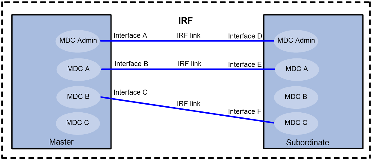
· The administrator of a non-default MDC can change the settings of an IRF physical interface that is assigned to the MDC. As a best practice, leave IRF physical interfaces to the default MDC. If you have to assign IRF physical interfaces to a non-default MDC, the two IRF physical interfaces of an IRF link can belong to the same MDC or different MDCs, as shown in Figure 1.
· To remove an LPU that holds the IRF physical interface of a non-default MDC, first complete the following tasks:
a. Remove the IRF physical interface configuration for the LPU.
b. Use the save command to save the running configuration.
· To assign an IRF physical interface to or reclaim it from an MDC, you must first shut it down and then remove its binding to the IRF port. Save the running configuration after assigning or reclaim the interface.
Restrictions and guidelines for interface configuration
· Assigning or reclaiming a physical interface restores the settings of the interface to the defaults.
· To configure parameters for a physical interface that has been assigned to an MDC, you must log in to the MDC.
CPU weight configuration
To ensure correct operation of all MDCs, assign them CPU weights. All MDCs authorized to use the same card share the CPU of the card. If one MDC occupies too many of the CPU resources, the other MDCs might not be able to operate.
The device supports adjusting CPU weights for MDCs without rebooting MDCs.
The number of CPU resources an MDC can use depends on the percentage of its CPU weight among the CPU weights of all MDCs that share the same CPU. For example, if three MDCs share the same CPU, setting their weights to 10, 10, and 5 is equivalent to setting their weights to 2, 2, and 1.
· The two MDCs with the same weight can use the CPU for approximately the same period of time.
· The third MDC can use the CPU for approximately half of the time for each of the other two MDCs.
The CPU weight specified for an MDC takes effect on all MPUs and all LPUs assigned to the MDC
Memory space allocation
The MDCs on a device share and compete for the system memory space. If an MDC occupies too much memory space, the other MDCs might not be able to operate correctly. To avoid this problem, specify a memory space percentage for each MDC.
Before you specify a memory space percentage for an MDC, use the display mdc resource command to view how much memory space the MDC is using. Make sure the memory space you assign to an MDC is sufficient for the MDC to operate correctly.
Cooperation between MDC and other protocols
To configure IRF MAD, create a VLAN. The VLAN is dedicated for MAD. MDCs cannot use the VLAN for packet forwarding.
You cannot deploy graceful restart between two MDCs configured on the same physical device or IRF fabric. If you fail to follow this rule, graceful restart will fail because of the absence of a GR helper.
MDC reboot
Non-default MDCs are isolated from each other. Rebooting a non-default MDC that does not hold an IRF physical interface does not affects the operation of the other MDCs.
If you reboot the only IRF physical interface in up state on an MDC, the system displays an error message. Removing or re-installing the IRF physical interface causes IRF split.
Rebooting the default MDC reboots the entire system, resulting in service outage.
Example: Configuring MDCs in standalone mode
Network configuration
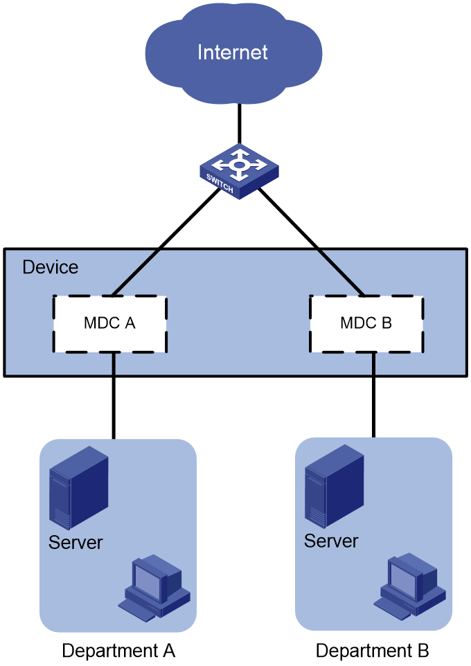
As shown in Figure 2, two departments need to use the device to access the Internet.
Configure two MDCs on the device to meet the Internet access requirements of two departments. Assign Ten-GigabitEthernet 2/0/1 through Ten-GigabitEthernet 2/0/24 to MDCA and Ten-GigabitEthernet 2/0/25 through Ten-GigabitEthernet 2/0/48 to MDCB.
Applicable hardware and software versions
The following matrix shows the hardware and software versions to which this configuration example is applicable:
|
Hardware |
Software version |
|
S12500G-AF switch series |
Release 7639P01 and later |
|
S10500X switch series |
Release 7639P01 and later |
|
S10500 switch series |
Release 7639P01 and later |
|
S7500E-X switch series |
Release 7639P01 and later |
|
S7500E switch series |
Release 7639P01 and later |
|
S7500X switch series |
Release 7639P01 and later |
Procedures
1. Create and configure MDCA and MDCB:
# Create MDCA for Department A.
<Device> system-view
[Device] mdc MDCA
It will take some time to create MDC...
MDC created successfully.
[Device-mdc-2-MDCA] quit
# Create MDCB for Department B.
[Device] mdc MDCB
It will take some time to create MDC...
MDC created successfully.
[Device-mdc-3-MDCB] quit
# Reclaim the LPU in slot 2 from the default MDC.
[Device] mdc Admin
[Device-mdc-1-Admin] undo location slot 2
Performing this command is equivalent to removing the card from the MDC. Continue? [Y/N]:y
[Device-mdc-1-Admin] quit
# Assign interfaces Ten-GigabitEthernet 2/0/1 through Ten-GigabitEthernet 2/0/24 to MDCA.
[Device] mdc MDCA
[Device-mdc-2-MDCA] allocate interface ten-gigabitethernet 2/0/1 to ten-gigabitethernet 2/0/24
Configuration of the interfaces will be lost. Continue? [Y/N]:y
Execute the location slot command in this view to make the configuration take effect.
# Assign interfaces Ten-GigabitEthernet 2/0/25 through Ten-GigabitEthernet 2/0/48 to MDCB.
[Device] mdc MDCB
[Device-mdc-3-MDCB] allocate interface ten-gigabitethernet 2/0/25 to ten-gigabitethernet 2/0/48
Configuration of the interfaces will be lost. Continue? [Y/N]:y
Execute the location slot command in this view to make the configuration take effect.
# Authorize MDCB to use the LPU in slot 2.
[Device-mdc-3-MDCB] location slot 2
# Set the CPU weight to 5 for MDCB.
[Device-mdc-3-MDCB] limit-resource cpu weight 5
# Start MDCB.
[Device-mdc-3-MDCB] mdc start
It will take some time to start MDC...
MDC started successfully.
[Device-mdc-3-MDCB] quit
# Authorize MDCA to use the LPU in slot 2.
[Device] mdc MDCA
[Device-mdc-2-MDCA] location slot 2
# Set the CPU weight to 5 for MDCA.
[Device-mdc-2-MDCA] limit-resource cpu weight 5
# Start MDCA.
[Device-mdc-2-MDCA] mdc start
It will take some time to start MDC...
MDC started successfully.
[Device-mdc-2-MDCA] quit
2. Configure the management Ethernet interface for MDCA:
# Log in to MDCA from the default MDC. Press Ctrl+D as prompted to access the CLI of MDCA.
[Device] switchto mdc MDCA
******************************************************************************
* Copyright (c) 2004-2018 New H3C Technologies Co., Ltd. All rights reserved.*
* Without the owner's prior written consent, *
* no decompiling or reverse-engineering shall be allowed. *
******************************************************************************
Automatic configuration is running, press CTRL_C or CTRL_D to break or press CTRL_B to switch back to the default MDC.
<Device> system-view
# Change the device name to MDCA for easy identification of the MDC.
[Device] sysname MDCA
# To enable the MDC administrator to remotely manage the MDC, assign an IP address to the management Ethernet interface and enable the Telnet service.
[MDCA] interface m-gigabitethernet 0/0/0
[MDCA-M-GigabitEthernet0/0/0] ip address 192.168.1.251 24
[MDCA-M-GigabitEthernet0/0/0] quit
[MDCA] telnet server enable
[MDCA] user-interface vty 0 63
[MDCA-line-vty0-63] authentication-mode none
[MDCA-line-vty0-63] user-role mdc-admin
# Return to the default MDC.
[MDCA-line-vty0-63] return
<MDCA> switchback
[Device]
3. Configure the management Ethernet interface for MDCB:
# Log in to MDCB from the default MDC. Press Ctrl+C as prompted to access the CLI of MDCB.
[Device] switchto mdc MDCB
******************************************************************************
* Copyright (c) 2004-2018 New H3C Technologies Co., Ltd. All rights reserved.*
* Without the owner's prior written consent, *
* no decompiling or reverse-engineering shall be allowed. *
******************************************************************************
Automatic configuration is running, press CTRL_C or CTRL_D to break or press CTRL_B to switch back to the default MDC.
<Device> system-view
# Change the device name to MDCB for easy identification of the MDC.
[Device] sysname MDCB
# To enable the MDC administrator to remotely manage the MDC, assign an IP address to the management Ethernet interface and enable the Telnet service.
[MDCB] interface m-gigabitethernet 0/0/0
[MDCB-M-GigabitEthernet0/0/0] ip address 192.168.2.252 24
[MDCB-M-GigabitEthernet0/0/0] quit
[MDCB] telnet server enable
[MDCB] user-interface vty 0 63
[MDCB-line-vty0-63] authentication-mode none
[MDCB-line-vty0-63] user-role mdc-admin
# Return to the default MDC.
[MDCB-line-vty0-63] return
<MDCB> switchback
[Device] quit
Verifying the configuration
1. Verify that the MDCs exist and are operating correctly.
<Device> display mdc
ID Name Status
1 Admin active
2 MDCA active
3 MDCB active
The output shows that the MDCs have been created and are operating correctly.
2. Log in to MDCA as an administrator of Department A and then view the current configuration of the MDC.
C:\> telnet 192.168.1.251
******************************************************************************
* Copyright (c) 2004-2018 New H3C Technologies Co., Ltd. All rights reserved.*
* Without the owner's prior written consent, *
* no decompiling or reverse-engineering shall be allowed. *
******************************************************************************
<MDCA> display current-configuration
...
Configuration files
· Device:
#
mdc Admin id 1
undo location slot 2
#
mdc MDCA id 2
location slot 2
limit-resource cpu weight 5
mdc start
allocate interface ten-gigabitethernet 2/0/1 to ten-gigabitethernet 2/0/24
#
mdc MDCB id 3
location slot 2
limit-resource cpu weight 5
mdc start
allocate interface ten-gigabitethernet 2/0/25 to ten-gigabitethernet 2/0/48
|
|
NOTE: To configure MDCs, you must follow the procedures. This configuration file records only the commands executed on the physical device. |
· MDCA:
#
sysname MDCA
#
telnet server enable
#
interface M-GigabitEthernet0/0/0
ip address 192.168.1.251 255.255.255.0
#
line vty 0 63
authentication-mode none
user-role mdc-admin
user-role mdc-operator
· MDCB:
#
sysname MDCB
#
telnet server enable
#
interface M-GigabitEthernet0/0/0
ip address 192.168.2.252 255.255.255.0
#
line vty 0 63
authentication-mode none
user-role mdc-admin
Example: Configuring MDCs in IRF mode
Network configuration
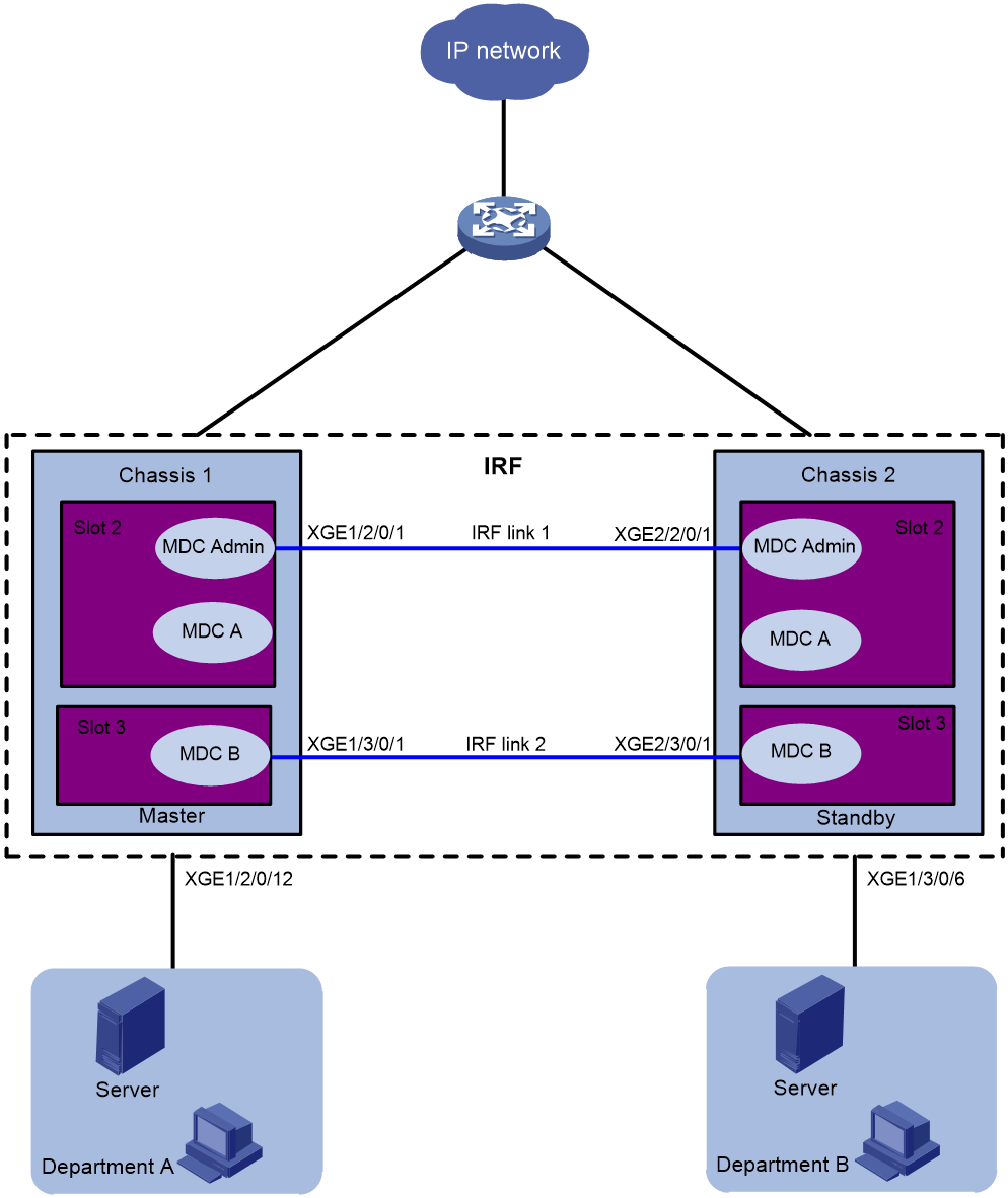
As shown in Figure 3, two departments need to use the IRF fabric to access the Internet. In the IRF fabric, each member device has two LPUs. Each LPU has 12 XGE interfaces.
The two member devices are connected with two IRF links. The IRF port on the master is IRF port 1. The IRF port on the subordinate member is IRF port 2. IRF port 1 is bound with Ten-GigabitEthernet 1/2/0/1 and Ten-GigabitEthernet 1/3/0/1. IRF port 2 is bound with Ten-GigabitEthernet 2/2/0/1 and Ten-GigabitEthernet 2/3/0/1.
Configure two MDCs on the IRF fabric to meet the Internet access requirements of two departments. Assign Ten-GigabitEthernet 1/2/0/7 through Ten-GigabitEthernet 1/2/0/12 and Ten-GigabitEthernet 2/2/0/7 through Ten-GigabitEthernet 2/2/0/12 to MDCA. Assign Ten-GigabitEthernet 1/3/0/1 through Ten-GigabitEthernet 1/3/0/6 and Ten-GigabitEthernet 2/3/0/1 through Ten-GigabitEthernet 2/3/0/6 to MDCB.
Applicable hardware and software versions
The following matrix shows the hardware and software versions to which this configuration example is applicable:
|
Hardware |
Software version |
|
S12500G-AF switch series |
Release 7639P01 and later |
|
S10500X switch series |
Release 7639P01 and later |
|
S10500 switch series |
Release 7639P01 and later |
|
S7500E-X switch series |
Release 7639P01 and later |
|
S7500E switch series |
Release 7639P01 and later |
|
S7500X switch series |
Release 7639P01 and later |
Analysis
Each member device must always have a minimum of one IRF link in up state during the MDC configuration. If you fail to do so, an IRF fabric split occurs. As a best practice, leave IRF physical interfaces to the default MDC if you have enough interface resources. However, the interface resources are limited because the interfaces are grouped. If you have to assign IRF physical interfaces to a non-default MDC, make sure the configuration steps are in the correct order. If not, the IRF physical interfaces might not be able to operate correctly.
To cover both scenarios, one pair of IRF physical interfaces is left to the default MDC and one pair is moved to non-default MDC MDCB in this example.
Procedures
1. Create MDCA and MDCB:
# Create MDCA for Department A.
<IRF> system-view
[IRF] mdc MDCA
It will take some time to create MDC...
MDC created successfully.
[IRF-mdc-2-MDCA] quit
The output shows that MDCA is created successfully. As a best practice, make sure MDCA is created successfully before you create MDCB.
# Create MDCB for Department B.
[IRF] mdc MDCB
It will take some time to create MDC...
MDC created successfully.
[IRF-mdc-3-MDCB] quit
The output shows that MDCB is created successfully. As a best practice, make sure MDCB is created successfully before you perform the following tasks.
2. Remove the bindings of Ten-GigabitEthernet 1/2/0/1 and Ten-GigabitEthernet 2/2/0/1 to IRF ports:
|
|
TIP: To avoid IRF fabric split, make sure the other IRF link is in up state while you are performing the following tasks. |
# Shut down Ten-GigabitEthernet 1/2/0/1 and Ten-GigabitEthernet 2/2/0/1.
[IRF] interface range ten-gigabitethernet 1/2/0/1 ten-gigabitethernet 2/2/0/1
[IRF-if-range] shutdown
[IRF-if-range] quit
# Remove the binding of Ten-GigabitEthernet 1/2/0/1 to IRF-port 1/1.
[IRF] irf-port 1/1
[IRF-irf-port1/1] undo port group interface ten-gigabitethernet1/2/0/1
[IRF-irf-port1/1] quit
# Remove the binding of Ten-GigabitEthernet 2/2/0/1 to IRF-port 2/2.
[IRF] irf-port 2/2
[IRF-irf-port2/2] undo port group interface ten-gigabitethernet2/2/0/1
[IRF-irf-port2/2] quit
3. Reclaim the LPU in slot 2 of each member device from the default MDC.
[IRF] mdc Admin
[IRF-mdc-1-Admin] undo location chassis 1 slot 2
Performing this command is equivalent to removing the card from the MDC. Continue? [Y/N]:y
[IRF-mdc-1-Admin] undo location chassis 2 slot 2
Performing this command is equivalent to removing the card from the MDC. Continue? [Y/N]:y
[IRF-mdc-1-Admin] quit
4. Assign resources to MDCA and start MDCA:
# Assign Ten-GigabitEthernet 1/2/0/7 through Ten-GigabitEthernet 1/2/0/12 and Ten-GigabitEthernet 2/2/0/7 through Ten-GigabitEthernet 2/2/0/12 to MDCA.
[IRF] mdc MDCA
[IRF-mdc-2-MDCA] allocate interface ten-gigabitEthernet 1/2/0/7 to ten-gigabitEthernet 1/2/0/12
Configuration of the interfaces will be lost. Continue? [Y/N]:y
Execute the location slot command in this view to make the configuration take effect.
[IRF-mdc-2-MDCA] allocate interface ten-gigabitEthernet 2/2/0/7 to ten-gigabitEthernet 2/2/0/12
Configuration of the interfaces will be lost. Continue? [Y/N]:y
Execute the location slot command in this view to make the configuration take effectt.
# Authorize MDCA to use the two LPUs.
[IRF-mdc-2-MDCA] location chassis 1 slot 2
[IRF-mdc-2-MDCA] location chassis 2 slot 2
# Set the CPU weight to 5 for MDCA.
[IRF-mdc-2-MDCA] limit-resource cpu weight 5
# Start MDCA.
[IRF-mdc-2-MDCA] mdc start
It will take some time to start MDC...
MDC started successfully.
[IRF-mdc-2-MDCA] quit
5. Re-authorize the default MDC to use the two LPUs.
[IRF] mdc Admin
[IRF-mdc-1-Admin] location chassis 1 slot 2
[IRF-mdc-1-Admin] location chassis 2 slot 2
[IRF-mdc-1-Admin] quit
6. Rebind Ten-GigabitEthernet 1/2/0/1 and Ten-GigabitEthernet 2/2/0/1 to IRF ports:
# Bind Ten-GigabitEthernet 1/2/0/1 to IRF-port 1/1.
[IRF] irf-port 1/1
[IRF-irf-port1/1] port group interface ten-gigabitethernet1/2/0/1
[IRF-irf-port1/1] quit
# Bind Ten-GigabitEthernet 2/2/0/1 to IRF-port 2/2.
[IRF] irf-port 2/2
[IRF-irf-port2/2] port group interface ten-gigabitethernet2/2/0/1
[IRF-irf-port2/2] quit
# Bring up the physical interfaces.
[irf] interface range ten-gigabitethernet 1/2/0/1 ten-gigabitethernet 2/2/0/1
[IRF-if-range] undo shutdown
[IRF-if-range] quit
7. Configure MDCA to enable remote access to MDCA:
# Log in to MDCA from the default MDC. Press Ctrl+D as prompted to stop automatic MDC configuration and access the CLI of MDCA.
[IRF] switchto mdc MDCA
******************************************************************************
* Copyright (c) 2004-2018 New H3C Technologies Co., Ltd. All rights reserved.*
* Without the owner's prior written consent, *
* no decompiling or reverse-engineering shall be allowed. *
******************************************************************************
Automatic configuration is running, press CTRL_C or CTRL_D to break or press CTRL_B to switch back to the default MDC.
<IRF> system-view
# Change the device name to MDCA for easy identification of the MDC.
[IRF] sysname MDCA
# Assign an IP address to the management interface and configure Telnet login.
[MDCA] display interface m-gigabitethernet brief
Brief information on interfaces in route mode:
Link: ADM - administratively down; Stby - standby
Protocol: (s) - spoofing
Interface Link Protocol Primary IP Description
M-GE1/0/0/0 DOWN DOWN --
M-GE1/0/0/1 DOWN DOWN --
M-GE1/0/0/2 UP UP --
M-GE1/0/0/3 DOWN DOWN --
[MDCA] interface m-gigabitethernet 1/0/0/2
[MDCA-M-GigabitEthernet1/0/0/2] ip address 192.168.1.251 24
[MDCA-M-GigabitEthernet1/0/0/2] quit
[MDCA] telnet server enable
[MDCA] user-interface vty 0 63
[MDCA-line-vty0-63] authentication-mode none
[MDCA-line-vty0-63] user-role mdc-admin
# Return to the default MDC.
[MDCA-line-vty0-63] return
<MDCA> switchback
[IRF]
8. Remove the bindings of Ten-GigabitEthernet 1/3/0/1 and Ten-GigabitEthernet 2/3/0/1 to IRF ports:
|
|
TIP: To avoid IRF fabric split, make sure the other IRF link is in up state while you are performing the following tasks. |
# Shut down Ten-GigabitEthernet 1/3/0/1 and Ten-GigabitEthernet 2/3/0/1.
[IRF] interface range ten-gigabitethernet 1/3/0/1 ten-gigabitethernet 2/3/0/1
[IRF-if-range] shutdown
[IRF-if-range] quit
# Remove the binding of Ten-GigabitEthernet 1/3/0/1 to IRF-port 1/1.
[IRF] irf-port 1/1
[IRF-irf-port1/1] undo port group interface ten-gigabitethernet1/3/0/1
[IRF-irf-port1/1] quit
# Remove the binding of Ten-GigabitEthernet 2/3/0/1 to IRF-port 2/2.
[IRF] irf-port 2/2
[IRF-irf-port2/2] undo port group interface ten-gigabitethernet2/3/0/1
[IRF-irf-port2/2] quit
9. Reclaim the LPU in slot 3 of each member device from the default MDC.
[IRF] mdc Admin
[IRF-mdc-1-Admin] undo location chassis 1 slot 3
Performing this command is equivalent to removing the card from the MDC. Continue? [Y/N]:y
[IRF-mdc-1-Admin] undo location chassis 2 slot 3
Performing this command is equivalent to removing the card from the MDC. Continue? [Y/N]:y
[IRF-mdc-1-Admin] quit
10. Assign resources to MDCB and start MDCB:
# Assign Ten-GigabitEthernet 1/3/0/1 through Ten-GigabitEthernet 1/3/0/6 and Ten-GigabitEthernet 2/3/0/1 through Ten-GigabitEthernet 2/3/0/6 to MDCB.
[IRF] mdc MDCB
[IRF-mdc-3-MDCB] allocate interface ten-gigabitethernet 1/3/0/1 to ten-gigabitethernet 1/3/0/6
Configuration of the interfaces will be lost. Continue? [Y/N]:y
Execute the location slot command in this view to make the configuration take effect.
[IRF-mdc-3-MDCB] allocate interface ten-gigabitEthernet 2/3/0/1 to ten-gigabitEthernet 2/3/0/6
Configuration of the interfaces will be lost. Continue? [Y/N]:y
Execute the location slot command in this view to make the configuration take effect.
# Authorize MDCB to use the two LPUs.
[IRF-mdc-3-MDCB] location chassis 1 slot 3
[IRF-mdc-3-MDCB] location chassis 2 slot 3
# Set the CPU weight to 5 for MDCB.
[IRF-mdc-3-MDCB] limit-resource cpu weight 5
# Start MDCB.
[IRF-mdc-3-MDCB] mdc start
It will take some time to start MDC...
MDC started successfully.
[IRF-mdc-3-MDCB] quit
11. Rebind Ten-GigabitEthernet 1/3/0/1 and Ten-GigabitEthernet 2/3/0/1 to IRF ports:
# Log in to MDCB from the default MDC. Press Ctrl+D as prompted to stop automatic MDC configuration and access the CLI of MDCB.
[IRF] switchto mdc MDCB
******************************************************************************
* Copyright (c) 2004-2018 New H3C Technologies Co., Ltd. All rights reserved.*
* Without the owner's prior written consent, *
* no decompiling or reverse-engineering shall be allowed. *
******************************************************************************
Automatic configuration is running, press CTRL_C or CTRL_D to break or press CTRL_B to switch back to the default MDC.
<IRF> system-view
# Change the device name to MDCB for easy identification of the MDC.
[IRF] sysname MDCB
# Shut down Ten-GigabitEthernet 1/3/0/1 and Ten-GigabitEthernet 2/3/0/1.
[MDCB] interface range ten-gigabitethernet 1/3/0/1 ten-gigabitethernet 2/3/0/1
[MDCB-if-range] shutdown
[MDCB-if-range] quit
[MDCB] quit
# Return to the default MDC.
<MDCB> switchback
[IRF]
# View the ID of MDCB.
[IRF] display mdc
ID Name Status
1 Admin active
2 MDCA active
3 MDCB active
# Bind Ten-GigabitEthernet 1/3/0/1 to IRF port 1/1.
[IRF] irf-port 1/1
[IRF-irf-port1/1] port group mdc 3 interface ten-gigabitethernet 1/3/0/1
[IRF-irf-port1/1] quit
# Bind Ten-GigabitEthernet 2/3/0/1 to IRF port 2/2.
[IRF] irf-port 2/2
[IRF-irf-port2/2] port group mdc 3 interface ten-gigabitethernet 2/3/0/1
[IRF-irf-port2/2] quit
# Log in to MDCB from the default MDC.
[IRF] switchto mdc MDCB
******************************************************************************
* Copyright (c) 2004-2018 New H3C Technologies Co., Ltd. All rights reserved.*
* Without the owner's prior written consent, *
* no decompiling or reverse-engineering shall be allowed. *
******************************************************************************
<MDCB> system-view
# Bring up Ten-GigabitEthernet 1/3/0/1 and Ten-GigabitEthernet 2/3/0/1.
[MDCB] interface range ten-gigabitethernet 1/3/0/1 ten-gigabitethernet 2/3/0/1
[MDCB-if-range] undo shutdown
[MDCB-if-range] quit
# Assign an IP address to the management interface and configure Telnet login.
[MDCB] display interface m-gigabitethernet brief
Brief information on interfaces in route mode:
Link: ADM - administratively down; Stby - standby
Protocol: (s) - spoofing
Interface Link Protocol Primary IP Description
M-GE1/0/0/0 DOWN DOWN --
M-GE1/0/0/1 DOWN DOWN --
M-GE1/0/0/2 UP UP --
M-GE1/0/0/3 DOWN DOWN --
[MDCB] interface m-gigabitethernet 1/0/0/2
[MDCB-M-GigabitEthernet1/0/0/2] ip address 192.168.2.252 24
[MDCB-M-GigabitEthernet1/0/0/2] quit
[MDCB] telnet server enable
[MDCB] user-interface vty 0 63
[MDCB-line-vty0-63] authentication-mode none
[MDCB-line-vty0-63] user-role mdc-admin
[MDCB-line-vty0-63] return
# Return to the default MDC.
<MDCB> switchback
[IRF]
12. Re-authorize the default MDC to use the two LPUs.
[IRF] mdc Admin
[IRF-mdc-1-Admin] location chassis 1 slot 3
[IRF-mdc-1-Admin] location chassis 2 slot 3
[IRF-mdc-1-Admin] quit
Verifying the configuration
1. Verify that the MDCs exist and are operating correctly.
[IRF] display mdc
ID Name Status
1 Admin active
2 MDCA active
3 MDCB active
The output shows that the MDCs have been created and are operating correctly.
2. Display IRF link information.
[IRF] display irf link
Member 1
IRF Port Interface Status
1 Ten-GigabitEthernet1/2/0/1(MDC1) UP
Ten-GigabitEthernet1/3/0/1(MDC3) UP
2 disable --
Member 2
IRF Port Interface Status
1 disable --
2 Ten-GigabitEthernet2/2/0/1(MDC1) UP
Ten-GigabitEthernet2/3/0/1(MDC3) UP
The output shows that two IRF links exist and are in up state. One IRF link is on the default MDC, and the other IRF link is on MDCB.
3. Log in to MDCA as an administrator of Department A. View the running configuration of the MDC.
C:\> telnet 192.168.1.251
******************************************************************************
* Copyright (c) 2004-2018 New H3C Technologies Co., Ltd. All rights reserved.*
* Without the owner's prior written consent, *
* no decompiling or reverse-engineering shall be allowed. *
******************************************************************************
<MDCA> display current-configuration
...
Configuration files
· IRF fabric:
#
mdc Admin id 1
undo location chassis 1 slot 3
undo location chassis 2 slot 3
#
mdc MDCA id 2
location chassis 1 slot 2
location chassis 2 slot 2
limit-resource cpu weight 5
mdc start
allocate interface ten-gigabitEthernet 1/2/0/7 to ten-gigabitEthernet 1/2/0/12
allocate interface ten-gigabitEthernet 2/2/0/7 to ten-gigabitEthernet 2/2/0/12
#
mdc MDCB id 3
location chassis 1 slot 3
location chassis 2 slot 3
limit-resource cpu weight 5
mdc start
allocate interface ten-gigabitEthernet 1/3/0/1 to ten-gigabitEthernet 1/3/0/6
allocate interface ten-gigabitEthernet 2/3/0/1 to ten-gigabitEthernet 2/3/0/6
#
sysname IRF
#
irf member 1 priority 1
irf member 2 priority 1
#
irf-port 1/1
port group interface Ten-GigabitEthernet1/2/0/1 mode enhanced
port group mdc 3 interface Ten-GigabitEthernet1/3/0/1 mode enhanced
#
irf-port 2/2
port group interface Ten-GigabitEthernet2/2/0/1 mode enhanced
port group mdc 3 interface Ten-GigabitEthernet2/3/0/1 mode enhanced
#
return
|
|
NOTE: To configure MDCs, you must follow the procedures. This configuration file records only the commands executed on the IRF fabric. |
· MDCA:
#
sysname MDCA
#
telnet server enable
#
interface M-GigabitEthernet1/0/0/0
ip address 192.168.1.251 255.255.255.0
#
line vty 0 63
authentication-mode none
user-role mdc-admin
user-role mdc-operator
#
return
· MDCB:
#
sysname MDCB
#
telnet server enable
#
interface M-GigabitEthernet1/0/0/0
ip address 192.168.2.252 255.255.255.0
#
line vty 0 63
authentication-mode none
user-role mdc-admin
user-role mdc-operator
#
return