- Table of Contents
- Related Documents
-
| Title | Size | Download |
|---|---|---|
| 02-IRF Configuration Examples | 704.61 KB |
General restrictions and guidelines
Restrictions and guidelines on IRF fabric setup
IRF physical interface requirements
Restrictions and guidelines after IRF fabric setup
Feature compatibility and configuration restrictions
Configuration rollback restrictions
Applicable hardware and software versions
Management IP address configuration restrictions and guidelines
Configuring management IP addresses
Applicable hardware and software versions
Management IP address configuration restrictions and guidelines
BFD MAD configuration restrictions and guidelines
Configuring management IP addresses
Example: Setting up a LACP MAD-enabled two-chassis IRF fabric
Applicable hardware and software versions
Verifying the link backup function of multichassis aggregations
Verifying the link backup function of IRF connections
Example: Setting up a LACP MAD-enabled four-chassis IRF fabric
Applicable hardware and software versions
Configuring IRF downlink services
Configuring IRF uplink services
Verifying the link backup function of multichassis aggregations
Example: Expanding an IRF fabric
Applicable hardware and software versions
Setting up the IRF fabric (by adding Device C and Device D to the IRF fabric)
Setting up the IRF fabric (by merging the old IRF fabric and IRF-C)
Configuring IRF downlink services
Configuring IRF uplink services
Verifying the link backup function of multichassis aggregations
Introduction
This document provides examples for setting up IRF fabrics and configuring link aggregation and routing on the IRF fabrics.
Prerequisites
The configuration examples in this document were created and verified in a lab environment, and all the devices were started with the factory default configuration. When you are working on a live network, make sure you understand the potential impact of every command on your network.
This document assumes that you have basic knowledge of IRF.
General restrictions and guidelines
IRF fabric size
S10500X
Make sure an S10500X IRF fabric contains only a maximum of two chassis if you are using the following features or configuration:
· PTP.
· More than eight IRF physical interfaces in an IRF port.
· Extended binding mode on IRF physical interfaces.
· Light IRF mode.
· IRF physical interfaces on SA modules or on any of the following SE modules:
¡ LSUM2GP44TSSE0
¡ LSUM2GP24TSSE0
¡ LSUM2GT24PTSSE0
¡ LSUM2GT24TSSE0
In any other situations, an S10500X IRF fabric can contain a maximum of four chassis.
S10500
Make sure an S10500 IRF fabric contains only a maximum of two chassis if you are using the following features or configuration:
· More than eight physical interfaces in an IRF port.
· Extended binding mode on IRF physical interfaces.
· Light IRF mode.
· Configure the 40-GE ports on the LSUM1MPU10A0 MPU of the S10510 switch as IRF physical interfaces.
· IRF physical interfaces on any of the following modules:
¡ SA modules.
¡ SE modules:
- LSUM2GP44TSSE0
- LSUM2GP24TSSE0
- LSUM2GT24PTSSE0
- LSUM2GT24TSSE0
In any other situations, an S10500 IRF fabric can contain a maximum of four chassis.
S7500E-X
Make sure an S7500E-X IRF fabric contains only a maximum of two chassis if you are using the following features or configuration:
· More than eight physical interfaces in an IRF port.
· Extended binding mode on IRF physical interfaces.
· Light IRF mode.
· Configure the 40-GE ports on the LSQM1MPU10A0 MPU of the S7510E-X switch as IRF physical interfaces.
· IRF physical interfaces on any of the following modules:
¡ SA modules.
¡ SC modules:
- LSQM2GP44TSSC0
- LSQM2GP24TSSC0
- LSQM2GT24PTSSC0
- LSQM2GT24TSSC0
In any other situations, an S7500E-X IRF fabric can contain a maximum of four chassis.
S7500E
Make sure an S7500E IRF fabric contains only a maximum of two chassis if you are using the following features, hardware, or configuration:
· More than eight physical interfaces in an IRF port.
· Extended binding mode on IRF physical interfaces.
· Light IRF mode.
· The IRF fabric contains S7503E-M member devices.
· The IRF member devices contain LSQM1PT8TSSC0, LSQM1PT24TSSC0, or LSQM1XPT12TSFD0 modules.
· Use the 10-GE or 40-GE ports on the LSQM2MPUD0 or LSQM1SRP8X2QE0 MPU as IRF physical interfaces.
· IRF physical interfaces on any of the following modules:
¡ SA modules.
¡ SC modules:
- LSQM2GP44TSSC0
- LSQM2GP24TSSC0
- LSQM2GT24PTSSC0
- LSQM2GT24TSSC0
In any other situations, an S7500E IRF fabric can contain a maximum of four chassis.
S7500X
Make sure an S7500X IRF fabric contains only a maximum of two chassis if you are using the following features, hardware, or configuration:
· More than eight physical interfaces in an IRF port.
· Extended binding mode on IRF physical interfaces.
· Light IRF mode.
· The IRF fabric contains S7503X member devices.
· The IRF member devices contain LSQM1PT8TSSC0, LSQM1PT24TSSC0, or LSQM1XPT12TSFD0 modules.
· IRF physical interfaces on any of the following modules:
¡ SA modules.
¡ SC modules:
- LSQM2GP44TSSC0
- LSQM2GP24TSSC0
- LSQM2GT24PTSSC0
- LSQM2GT24TSSC0
In any other situations, an S7500X IRF fabric can contain a maximum of four chassis.
Restrictions and guidelines on IRF fabric setup
· The S10506X and S10510X switches in the H3C S10500X series can form a multimodel IRF fabric only with each other. Any other switches in the series can form an IRF fabric with each other except with the S10506X or S10510X.
· An H3C S10500 switch can form an IRF fabric only with devices in the same series.
· An H3C S7500E-X switch can form an IRF fabric only with devices in the same series.
· All S7500E switches are IRF capable except for the S7502E switch. The H3C S7503E-M switch can form an IRF fabric only with switches of the same model. Other IRF-capable H3C S7500E switches can form an IRF fabric with any IRF-capable switches in the same series except the S7503E-M switch.
· All S7500X switches are IRF capable. The H3C S7503X switch can form an IRF fabric only with switches of the same model. Other H3C S7500X switches can form an IRF fabric with switches in the same series except the S7503X switch.
· All member devices in an IRF fabric must use the same MPU model.
· All IRF member devices must run the same system software version. Make sure the software auto-update feature is enabled on all member devices.
· If two IRF fabrics use the same bridge MAC address, you must configure a new bridge MAC address for either of the IRF fabrics. If you fail to do so, they cannot be merged into an IRF fabric.
· Before multiple devices form an IRF fabric, make sure they meet the following requirements:
¡ They have the same upper limit on the number of ECMP routes. For more information about setting the maximum number of ECMP routes, see IP routing basics configuration in Layer 3—IP Routing Configuration Guide.
¡ They are operating in the same mode. For more information about system operating mode, see system management configuration in Fundamentals Configuration Guide.
¡ They are in the same IRF mode.
IRF physical interface requirements
· For S7500E, S7500X, S10500, and S10500X switch series:
If ports on the EC modules are used as IRF physical ports, 10-GE ports on the EC modules are grouped by port number in order, starting from the lowest number. Each group contains four contiguous ports.
· For S7500E, S7500X, and S7500E-X switch series:
If ports on the SF modules are used as IRF physical ports, those ports are divided into the following groups:
¡ Ports 1, 2, 15, and 16.
¡ Ports 3, 4, and 5.
¡ Ports 6, 7, and 8.
¡ Ports 9, 10, and 11.
¡ Ports 12, 13, and 14.
· For S7500E, S7500X, S10500, S10500X, and S7500E-X switch series:
The using tengige command can break out a 40-GE port into four 10-GE interfaces and those 10-GE breakout interfaces belong to one port group. If you use a 40-GE port as an IRF physical interface, no grouping restrictions exist. If you use the 10-GE breakout interfaces of a 40-GE port for IRF links, follow these restrictions and guidelines:
¡ If you use one breakout interface as an IRF physical interface, the remaining breakout interfaces can only act as IRF physical interfaces. You cannot use them for any other purposes. To use a breakout interface for any purpose other than IRF physical interfaces, do not bind any of the interfaces to an IRF port.
¡ You must shut down all the breakout interfaces before you can assign or remove any of the interfaces to or from an IRF port. To bring up the interfaces after the assignment or removal is complete, execute the undo shutdown command.
· For the S10500X switch series:
The ports on the LSUM1YGS48XSH0 module are grouped by port number in order, starting from 1. Each group contains four contiguous ports. If you plan to change the speed of a port on this module, do not bind any of the ports in the same port group as this port to an IRF port. The IRF port binding operation will restore the speed of all ports in the same port group to the default. In addition, you cannot use the speed command to change the speed of any ports in the port group after the binding operation. For more information about this command, see Ethernet interface management in Interface Configuration Guide.
· For the S7500E switch series:
If you use 10-GE or 40-GE ports on the LSQM2MPUD0 or LSQM1SRP8X2QE0 MPU for IRF links, follow these restrictions and guidelines:
¡ Ports on interface modules cannot be used for IRF links.
¡ Ports bound to all IRF ports in an IRF fabric must be located on the same type of MPU.
· For the 10500 switch series:
The 10-GE ports on the LSUM2MPU10C0 MPU cannot be used for IRF links.
If you use 40-GE ports on the LSUM1MPU10A0 MPUs of a member device to establish IRF links, follow these restrictions and guidelines:
¡ Ports on interface modules cannot be used for IRF links.
¡ The peer IRF member device must also use 40-GE ports on its LSUM1MPU10A0 MPUs to establish IRF links.
¡ On each member device, you can use only one of the IRF ports to establish IRF links. The ports bound to the IRF port can only be 40-GE ports on the LSUM1MPU10A8 MPUs.
· For the S7500E-X switch series:
The 10-GE ports on the LSQM2MPU10C0 MPUs cannot be used for IRF links.
If you use 40-GE ports on the LSQM1MPU10A0 MPUs of a member device to establish IRF links, follow these restrictions and guidelines:
¡ Ports on interface modules cannot be used for IRF links.
¡ The peer IRF member device must also use 40-GE ports on its LSQM1MPU10A0 MPUs to establish IRF links.
¡ On each member device, you can use only one of the IRF ports to establish IRF links. The ports bound to the IRF port can only be 40-GE ports on the LSQM1MPU10A0 MPUs.
· For the S7500E, S7500X, S10500, S10500X, and S7500E-X switch series:
Interface modules with 40-GE QSFP+ ports can be used for IRF links. When you split a 40-GE QSFP+ port into four 10-GE breakout ports or merge the 10-GE breakout ports of a 40-GE QSFP+ port, you must restart the related interface module. After the IRF fabric is set up, interface module restart might affect the IRF topology. As a best practice to avoid this issue, make a deployment plan of 40-GE QSFP+ ports in advance.
· In standalone mode, binding IRF physical ports to IRF ports will not affect the current services running on those IRF physical ports. After the device starts operating in IRF mode, the bound IRF physical ports will be restored to the default and their original services will be cleared. In this situation, the IRF physical ports only support the following commands:
¡ For the S10500, S10500X, and S7500E-X switch series:
- shutdown
- description
- flow-interval
- priority-flow-control
- priority-flow-control no-drop dot1p
For more information about these commands, see Ethernet interface commands in Interface Command Reference.
¡ For the S7500E and S7500X switch series:
- shutdown
- description
- flow-interval
For more information about these commands, see Ethernet interface commands in Interface Command Reference.
¡ LLDP commands, such as lldp admin-status, lldp check-change-interval, lldp enable, lldp encapsulation snap, lldp notification remote-change enable, and lldp tlv-enable. For more information about these commands, see LLDP commands in Layer 2—LAN Switching Command Reference.
¡ For the S10500X and S7500X switch series:
Ethernet synchronization commands, such as esmc enable, synchronous mode, and synce state. For more information about these commands, see network synchronization commands in Network Management and Monitoring Command Reference.
¡ MAC configuration commands, such as mac-address static source-check enable. For more information about these commands, see MAC address table commands in Layer 2—LAN Switching Command Reference.
¡ port service-loopback group
This command adds a port to a service loopback group. Once this command is configured on an IRF physical port, the IRF port bindings of the physical port will be cleared. To avoid IRF split, do not configure this command when an IRF port is bound to only one physical port. For more information about this command, see service loopback group commands in Layer 2—LAN Switching Command Reference.
· For PTP to operate correctly on the S10500X switch series, make sure all IRF physical interfaces are located on SH interface modules. For more information about PTP, see Network Management and Monitoring Configuration Guide.
Restrictions and guidelines after IRF fabric setup
· After Ethernet interfaces are bound to IRF ports as IRF physical ports, they only support the following commands:
¡ Basic interface configuration commands, such as shutdown and description. For more information about these commands, see Ethernet interface commands in Interface Command Reference.
¡ flow-interval
This command sets the interface statistics polling interval. For more information about this command, see Ethernet interface commands in Interface Command Reference.
¡ For the S10500, S10500X, and S7500E-X switch series:
PFC commands, such as priority-flow-control and priority-flow-control no-drop dot1p. For more information about these commands, see Ethernet interface commands in Interface Command Reference.
¡ port link-flap protect enable
This command enables link flapping protection on an interface. To prevent IRF link flapping from interrupting the IRF fabric, link flapping protection is enabled on all IRF physical ports by default. The enabling status of this feature on an IRF physical port does not depend on the global enabling status of this feature. During a link flapping detection interval, if the number of detected flaps reaches or exceeds the corresponding link flapping detection threshold, the device will generate a notification, but not shut down the IRF physical port. For more information about this command, see Ethernet interface commands in Interface Command Reference.
¡ LLDP commands, such as lldp admin-status, lldp check-change-interval, lldp enable, lldp encapsulation snap, lldp notification remote-change enable, and lldp tlv-enable. For more information about these commands, see LLDP commands in Layer 2—LAN Switching Command Reference.
¡ For the S10500X and S7500X switch series:
Ethernet synchronization commands, such as esmc enable, synchronous mode, and synce state. For more information about these commands, see network synchronization commands in Network Management and Monitoring Command Reference.
¡ MAC configuration commands, such as mac-address static source-check enable. For more information about these commands, see MAC address table commands in Layer 2—LAN Switching Command Reference.
¡ port service-loopback group
This command adds a port to a service loopback group. Once this command is configured on an IRF physical port, the IRF port bindings of the physical port will be cleared. To avoid IRF split, do not configure this command when an IRF port is bound to only one physical port. For more information about this command, see service loopback group commands in Layer 2—LAN Switching Command Reference.
· Because MAD mechanisms use different collision handling processes, follow these restrictions and guidelines when you configure multiple MAD mechanisms on an IRF fabric:
¡ Do not configure LACP MAD together with ARP MAD or ND MAD.
¡ Do not configure BFD MAD together with ARP MAD or ND MAD.
· If LACP MAD, ARP MAD, or ND MAD runs between two IRF fabrics, assign each fabric a unique IRF domain ID. (For BFD MAD, this task is optional.)
· An IRF fabric has only one IRF domain ID. You can change the IRF domain ID by using the following commands: irf domain, mad enable, mad arp enable, or mad nd enable. The IRF domain IDs configured by using these commands overwrite each other.
· If you change the IRF domain ID in one MDC, the IRF domain IDs in all other MDCs change automatically. The irf domain command is available only on the default MDC. The mad enable, mad arp enable, and mad nd enable commands are available on any MDCs.
· In a Recovery-state fabric, all common network interfaces will be shut down except for the following interfaces:
¡ Interfaces automatically excluded from being shut down by the system.
¡ Interfaces specified by using the mad exclude interface command.
· To prevent a multi-active collision from causing network issues, avoid using the undo shutdown command to bring up the interfaces shut down by a MAD mechanism on a Recovery-state IRF fabric.
· If ARP MAD or ND MAD is used with the spanning tree feature, you must disable IRF bridge MAC persistence by using the undo irf mac-address persistent command. In addition, do not specify a MAC address as the IRF bridge MAC address.
· If the IRF fabric has multichassis aggregate links, do not use the undo irf mac-address persistent command. Use of this command might cause traffic disruption.
· For a license-based feature to run correctly on an IRF fabric, make sure the licenses installed for the feature on all member devices are the same.
· If you insert a new MPU or replace an MPU after IRF fabric setup, make sure the new MPU and the IRF fabric are in the same IRF mode.
Feature compatibility and configuration restrictions
System operating mode
All member devices in the IRF fabric must work in the same system operating mode (set by using the system-working-mode command). For more information about the system operating mode, see device management in Fundamentals Configuration Guide.
MDC
When you configure MDC on an IRF fabric, follow these restrictions and guidelines:
· If the IRF fabric splits, do not change the MDC and IRF settings on any IRF member devices before they reunite.
· Before you use the undo mdc command to delete an MDC, remove IRF port bindings for the physical interfaces on the MDC and save the configuration. To identify physical interfaces bound to IRF ports, use the display irf link command.
· Except for the commands in Table 1, all IRF commands are available only on the default MDC.
Table 1 IRF commands available on both default and non-default MDCs
|
Command category |
Commands |
|
Display commands |
· display irf link · display mad |
|
MAD commands |
· mad arp enable · mad enable · mad nd enable · mad exclude interface |
For more information about MDCs, see MDC configuration in Virtual Technologies Configuration Guide.
Routing configuration
To form an IRF fabric, all member devices must use the same setting for the maximum number of ECMP routes (set by using the max-ecmp-num command). For more information about ECMP, see IP routing basics in Layer 3—IP Routing Configuration Guide.
Configuration rollback restrictions
The configuration rollback feature cannot roll back the following IRF settings:
· Member device description (set by using the irf member description command).
· Member device priority (set by using the irf member priority command).
· IRF physical interface and IRF port bindings (set by using the port group interface command).
For more information about the configuration rollback feature, see configuration file management in Fundamentals Configuration Guide.
Example: Setting up a two-chassis IRF fabric with ARP MAD and management IP configured on the same management Ethernet port
About this example
This example configures ARP MAD on management Ethernet ports without affecting network management functions. After an IRF split, you can log in to the split IRF fabrics separately for troubleshooting purposes.
This example is also applicable to a two-chassis IRF fabric running ND MAD, except that you must configure ND MAD differently. For more information about MAD configuration, see the virtual technologies configuration guide for the device.
Network configuration
As shown in Figure 1, use Device A and Device B to set up a two-chassis IRF fabric.
Use management Ethernet port M-GigabitEthernet 0/0/0 to perform ARP MAD for IRF split detection and to provide device access for management purposes.
Configure management IP addresses for the IRF fabric and each member device on the management port to meet the following requirements:
· The administrator can use the same management IP address to access the IRF fabric before and after a master/subordinate switchover.
· The administrator can access each member device for failure recovery through their respective management IP addresses after the IRF fabric splits.

Applicable hardware and software versions
The following matrix shows the hardware and software versions to which this configuration example is applicable:
|
Hardware |
Software version |
|
S12500G-AF switch series |
Release 7639P01 and later |
|
S10500X switch series |
Release 7639P01 and later |
|
S10500 switch series |
Release 7639P01 and later |
|
S7500E-X switch series |
Release 7639P01 and later |
|
S7500E switch series |
Release 7639P01 and later |
|
S7500X switch series |
Release 7639P01 and later |
Restrictions and guidelines
Management IP address configuration restrictions and guidelines
When you configure ARP MAD:
· Connect a management Ethernet port on each member device to the common Ethernet ports on the intermediate device. To avoid ARP MAD failure caused by an active/standby MPU switchover, connect the management Ethernet ports on each MPU to the intermediate device.
· On the intermediate device, perform the following tasks:
¡ Create a VLAN for ARP MAD.
¡ If the intermediate device is also an IRF fabric, assign the two IRF fabrics different domain IDs for correct split detection.
When you configure management IP addresses, follow these restrictions and guidelines:
· To make sure you can access the IRF fabric at the same IP address after a master/subordinate switchover, use the ip address ip-address { mask-length | mask } command to configure a management IP address on the management port, in this example, on M-GigabitEthernet 0/0/0. You can use this address to access the IRF fabric as long as the fabric has not split. This address might be inaccessible for an IP conflict after the IRF fabric splits, because it exists on all member devices. In the context of IRF, this address is called a global management IP address.
· To access each member device for failure recovery after the IRF fabric splits, use the ip address ip-address { mask-length | mask } irf-member member-id command to configure a management IP address for each member device on the management port, in this example, on M-GigabitEthernet 0/0/0. In the context of IRF, this address is called a member-specific management IP address.
· Make sure the management IP addresses assigned to all IRF member devices on the same management Ethernet port belong to the same subnet. Make sure the management IP addresses assigned to an IRF member device on different management Ethernet ports belong to different subnets.
· You must manually make sure the management IP addresses configured on the subordinate devices will not cause IP address conflicts on the network. When the IRF fabric is running correctly, only the IP addresses of the management Ethernet ports on the master device take effect. The management IP addresses of the management Ethernet ports on the subordinate devices do not take effect. If a management IP address on a subordinate device conflicts with an IP address in the network, the system cannot detect the IP conflict, causing network issues after an IRF split.
|
|
NOTE: When the IRF fabric is integrated, you can access the IRF fabric by using either the global management IP address or the management IP address specific to the master device. As a best practice to prevent the management IP address from changing upon a master/subordinate switchover, use the global management IP address as long as the IRF fabric is integrated. |
Procedures
Setting up the IRF fabric
1. Configure Device A:
# Shut down the physical interfaces used for IRF connection. This example uses Ten-GigabitEthernet 1/0/1 and Ten-GigabitEthernet 1/0/2 for IRF connection.
<DeviceA> system-view
[DeviceA] interface range ten-gigabitEthernet1/0/1 to ten-gigabitEthernet1/0/2
[DeviceA-if-range] shutdown
[DeviceA-if-range] quit
# Bind Ten-GigabitEthernet 1/0/1 and Ten-GigabitEthernet 1/0/2 to IRF-port 1/2.
[DeviceA] irf-port 1/2
[DeviceA-irf-port1/2] port group interface ten-gigabitEthernet1/0/1
[DeviceA-irf-port1/2] port group interface ten-gigabitEthernet1/0/2
[DeviceA-irf-port1/2] quit
# Bring up the physical interfaces.
[DeviceA] interface range ten-gigabitEthernet1/0/1 to ten-gigabitEthernet1/0/2
[DeviceA-if-range] undo shutdown
[DeviceA-if-range] quit
# Save the running configuration to the next-startup configuration file.
[DeviceA] quit
<DeviceA> save
# Activate the IRF port configuration.
<DeviceA> system-view
[DeviceA] irf-port-configuration active
2. Configure Device B:
# Assign member ID 2 to Device B, and reboot the device to have the change take effect.
<DeviceB> system-view
[DeviceB] irf member 1 renumber 2
Renumbering the member ID may result in configuration change or loss. Continue? [Y/N]:y
[DeviceB] quit
<DeviceB> reboot
# Shut down the physical interfaces used for IRF connection. This example uses Ten-GigabitEthernet 2/0/1 and Ten-GigabitEthernet 2/0/2 for IRF connection.
<DeviceB> system-view
[DeviceB] interface range ten-gigabitEthernet2/0/1 to ten-gigabitEthernet2/0/2
[DeviceB-if-range] shutdown
[DeviceB-if-range] quit
# Bind Ten-GigabitEthernet 2/0/1 and Ten-GigabitEthernet 2/0/2 to IRF-port 2/1.
[DeviceB] irf-port 2/1
[DeviceB-irf-port2/1] port group interface ten-gigabitEthernet2/0/1
[DeviceB-irf-port2/1] port group interface ten-gigabitEthernet2/0/2
[DeviceB-irf-port2/1] quit
# Bring up the physical interfaces.
[DeviceB] interface range ten-gigabitEthernet2/0/1 to ten-gigabitEthernet2/0/2
[DeviceB-if-range] undo shutdown
[DeviceB-if-range] quit
# Save the running configuration to the next-startup configuration file.
[DeviceB] quit
<DeviceB> save
# Connect Device B to Device A, as shown in Figure 1.
# Activate the IRF port configuration.
<DeviceB> system-view
[DeviceB] irf-port-configuration active
Device A and Device B perform master election. The device that has failed master election automatically reboots to form an IRF fabric with the other device. A two-chassis IRF fabric is formed.
Configuring management IP addresses
# Assign IP address 192.168.1.1/24 to the IRF fabric on management Ethernet port M-GigabitEthernet 0/0/0.
<IRF> system-view
[IRF] interface m-gigabitethernet 0/0/0
[IRF-M-GigabitEthernet0/0/0] ip address 192.168.1.1 24
# On management Ethernet port M-GigabitEthernet 0/0/0, assign IP addresses 192.168.1.101/24 and 192.168.1.102/24 to IRF member device 1 (Device A) and IRF member device 2 (Device B), respectively. After the IRF fabric splits, the administrator can use IP addresses 192.168.1.101/24 and 192.168.1.102/24 to log in to Device A and Device B, respectively.
[IRF-M-GigabitEthernet0/0/0] ip address 192.168.1.101 24 irf-member 1
[IRF-M-GigabitEthernet0/0/0] ip address 192.168.1.102 24 irf-member 2
[IRF-M-GigabitEthernet0/0/0] quit
# Exclude management Ethernet port M-GigabitEthernet 0/0/0 from being shut down by MAD upon detection of multi-active collisions.
[IRF] mad exclude interface m-gigabitethernet 0/0/0
Configuring ARP MAD
1. Configure the IRF fabric:
# Configure the IRF fabric to change its bridge MAC address as soon as the address owner leaves.
[IRF] undo irf mac-address persistent
# Set the domain ID of the IRF fabric to 1.
[IRF] irf domain 1
# Enable ARP MAD on management Ethernet port M-GigabitEthernet 0/0/0.
[IRF] interface m-gigabitethernet 0/0/0
[IRF-M-GigabitEthernet0/0/0] mad arp enable
You need to assign a domain ID (range: 0-4294967295)
[Current domain ID is: 1]:
The assigned domain ID is: 1
[IRF-M-GigabitEthernet0/0/0] quit
# Save the running configuration to the next-startup configuration file.
[IRF] save
2. Configure Device C as the intermediate device:
# Create VLAN 100.
<DeviceC> system-view
[DeviceC] vlan 100
# Assign GigabitEthernet1/0/1 and GigabitEthernet1/0/2 to VLAN 100 for forwarding ARP MAD packets.
[DeviceC-vlan100] port gigabitethernet 1/0/1 to gigabitethernet 1/0/4
[DeviceC-vlan100] quit
Verifying the configuration
# Disconnect the IRF links between Device A and Device B. Verify that you can use 192.168.1.101 and 192.168.1.102 to log in to Device A and Device B, respectively. (Details not shown.)
# Execute the display mad verbose command on Device A and Device B to verify that MAD is correctly functioning, as follows:
· The Multi-active recovery state field displays Yes on one device and displays No on the other device.
· On each device, the IRF physical interfaces and management Ethernet port M-GigabitEthernet 0/0/0 are excluded from being shut down by MAD.
# Execute the display interface brief command on Device A and Device B to verify that the MAD shutdown action is performed correctly, as follows:
· On the device in Recovery state, all network interfaces have been shut down by MAD except the IRF physical interfaces and management Ethernet port M-GigabitEthernet 0/0/0.
· On the device not in Recovery state, no network interfaces are shut down by MAD.
Configuration files
IRF fabric
#
irf-port 1/2
port group interface Ten-GigabitEthernet1/0/1
port group interface Ten-GigabitEthernet1/0/2
#
irf-port 2/1
port group interface Ten-GigabitEthernet2/0/1
port group interface Ten-GigabitEthernet2/0/2
#
irf domain 1
undo irf mac-address persistent
#
interface M-GigabitEthernet0/0/0
ip address 192.168.1.1 255.255.255.0
ip address 192.168.1.101 255.255.255.0 irf-member 1
ip address 192.168.1.102 255.255.255.0 irf-member 2
mad arp enable
#
mad exclude interface M-GigabitEthernet0/0/0
#
Device C
#
vlan 100
#
GigabitEthernet 1/0/1
port access vlan 100
#
Gigabitethernet 1/0/2
port access vlan 100
#
Example: Setting up a two-chassis IRF fabric with BFD MAD and management IP configured on separate management Ethernet ports
About this example
This example is applicable to the devices that have two management Ethernet interfaces. You can use one management Ethernet interface for management purposes and the other for the sole purposes of BFD MAD. After an IRF split, you can log in to the split IRF fabrics separately for troubleshooting purposes.
This example is also applicable to a two-chassis IRF fabric running ARP MAD or ND MAD, except that you must configure ARP MAD and ND MAD differently. For more information about MAD configuration, see the virtual technologies configuration guide for the device.
Network configuration
As shown in Figure 2, use Device A and Device B to set up a two-chassis IRF fabric.
Use management Ethernet port M-GigabitEthernet 0/0/0 on Device A and Device B for device management purposes. Configure management IP addresses for the IRF fabric and each member device on the management port to meet the following requirements:
· The administrator can use the same management IP address to access the IRF fabric before and after a master/subordinate switchover.
· The administrator can access each member device for failure recovery through their respective management IP addresses after the IRF fabric splits.
Use management Ethernet port M-GigabitEthernet 0/0/1 to perform BFD MAD for IRF split detection.

Applicable hardware and software versions
The following matrix shows the hardware and software versions to which this configuration example is applicable:
|
Hardware |
Software version |
|
S12500G-AF switch series |
Release 7639P01 and later |
|
S10500X switch series |
Release 7639P01 and later |
|
S10500 switch series |
Release 7639P01 and later |
|
S7500E-X switch series |
Release 7639P01 and later |
|
S7500E switch series |
Release 7639P01 and later |
|
S7500X switch series |
Release 7639P01 and later |
Restrictions and guidelines
Management IP address configuration restrictions and guidelines
When you configure management IP addresses, follow these restrictions and guidelines:
· To make sure you can access the IRF fabric at the same IP address after a master/subordinate switchover, use the ip address ip-address { mask-length | mask } command to configure a management IP address on the management port, in this example, on M-GigabitEthernet 0/0/0. You can use this address to access the IRF fabric as long as the fabric has not split. This address might be inaccessible for an IP conflict after the IRF fabric splits, because it exists on all member devices. In the context of IRF, this address is called a global management IP address.
· To access each member device for failure recovery after the IRF fabric splits, use the ip address ip-address { mask-length | mask } irf-member member-id command to configure a management IP address for each member device on the management port, in this example, on M-GigabitEthernet 0/0/0. In the context of IRF, this address is called a member-specific management IP address.
· Make sure the management IP addresses assigned to all IRF member devices on the same management Ethernet port belong to the same subnet. Make sure the management IP addresses assigned to an IRF member device on different management Ethernet ports belong to different subnets.
· You must manually make sure the management IP addresses configured on the subordinate devices will not cause IP address conflicts on the network. When the IRF fabric is running correctly, only the IP addresses of the management Ethernet ports on the master device take effect. The management IP addresses of the management Ethernet ports on the subordinate devices do not take effect. If a management IP address on a subordinate device conflicts with an IP address in the network, the system cannot detect the IP conflict, causing network issues after an IRF split.
|
|
NOTE: When the IRF fabric is integrated, you can access the IRF fabric by using either the global management IP address or the management IP address specific to the master device. As a best practice to prevent the management IP address from changing upon a master/subordinate switchover, use the global management IP address as long as the IRF fabric is integrated. |
BFD MAD configuration restrictions and guidelines
When you configure BFD MAD on a management Ethernet port, follow these restrictions and guidelines:
|
Category |
Restrictions and guidelines |
|
Management Ethernet ports for BFD MAD |
Connect a management Ethernet port on each IRF member device to the common Ethernet ports on the intermediate device. |
|
BFD MAD VLAN |
· On the intermediate device, create a VLAN for BFD MAD, and assign the ports used for BFD MAD to the VLAN. On the IRF fabric, you do not need to assign the management Ethernet ports to the VLAN. · Make sure the IRF fabrics on the network use different BFD MAD VLANs. · Make sure the BFD MAD VLAN on the intermediate device contains only ports on the BFD MAD links. |
|
MAD IP address |
· To avoid network issues, only use the mad ip address command to configure IP addresses on the BFD MAD-enabled management Ethernet port. Do not configure an IP address by using the ip address command or configure a VRRP virtual address on the BFD MAD-enabled management Ethernet port. · Make sure all the MAD IP addresses are on the same subnet. |
Procedures
Setting up the IRF fabric
1. Configure Device A:
# Shut down the physical interfaces used for IRF connection. This example uses Ten-GigabitEthernet 1/0/1 and Ten-GigabitEthernet 1/0/2 for IRF connection.
<DeviceA> system-view
[DeviceA] interface range ten-gigabitEthernet1/0/1 to ten-gigabitEthernet1/0/2
[DeviceA-if-range] shutdown
[DeviceA-if-range] quit
# Bind Ten-GigabitEthernet 1/0/1 and Ten-GigabitEthernet 1/0/2 to IRF-port 1/2.
[DeviceA] irf-port 1/2
[DeviceA-irf-port1/2] port group interface ten-gigabitEthernet1/0/1
[DeviceA-irf-port1/2] port group interface ten-gigabitEthernet1/0/2
[DeviceA-irf-port1/2] quit
# Bring up the physical interfaces.
[DeviceA] interface range ten-gigabitEthernet1/0/1 to ten-gigabitEthernet1/0/2
[DeviceA-if-range] undo shutdown
[DeviceA-if-range] quit
# Save the running configuration to the next-startup configuration file.
[DeviceA] quit
<DeviceA> save
# Activate the IRF port configuration.
<DeviceA> system-view
[DeviceA] irf-port-configuration active
2. Configure Device B:
# Assign member ID 2 to Device B, and reboot the device to have the change take effect.
<DeviceB> system-view
[DeviceB] irf member 1 renumber 2
Renumbering the member ID may result in configuration change or loss. Continue? [Y/N]:y
[DeviceB] quit
<DeviceB> reboot
# Shut down the physical interfaces used for IRF connection. This example uses Ten-GigabitEthernet2/0/1 and Ten-GigabitEthernet2/0/2 for IRF connection.
<DeviceB> system-view
[DeviceB] interface range ten-gigabitEthernet2/0/1 to ten-gigabitEthernet2/0/2
[DeviceB-if-range] shutdown
[DeviceB-if-range] quit
# Bind Ten-GigabitEthernet 2/0/1 and Ten-GigabitEthernet 2/0/2 to IRF-port 2/1.
[DeviceB] irf-port 2/1
[DeviceB-irf-port2/1] port group interface ten-gigabitEthernet2/0/1
[DeviceB-irf-port2/1] port group interface ten-gigabitEthernet2/0/2
[DeviceB-irf-port2/1] quit
# Bring up the physical interfaces.
[DeviceB] interface range ten-gigabitEthernet2/0/1 to ten-gigabitEthernet2/0/2
[DeviceB-if-range] undo shutdown
[DeviceB-if-range] quit
# Save the running configuration to the next-startup configuration file.
[DeviceB] quit
<DeviceB> save
# Connect Device B to Device A, as shown in Figure 2.
# Activate the IRF port configuration.
<DeviceB> system-view
[DeviceB] irf-port-configuration active
Device A and Device B perform master election. The device that has failed master election automatically reboots to form an IRF fabric with the other device.
Configuring management IP addresses
# Assign IP address 192.168.1.1/24 to the IRF fabric on management Ethernet port M-GigabitEthernet 0/0/0.
<IRF> system-view
[IRF] interface m-gigabitethernet 0/0/0
[IRF-M-GigabitEthernet0/0/0] ip address 192.168.1.1 24
# On management Ethernet port M-GigabitEthernet 0/0/0, assign IP addresses 192.168.1.101/24 and 192.168.1.102/24 to IRF member device 1 (Device A) and IRF member device 2 (Device B), respectively. After the IRF fabric splits, the administrator can use IP addresses 192.168.1.101/24 and 192.168.1.102/24 to log in to Device A and Device B, respectively.
[IRF-M-GigabitEthernet0/0/0] ip address 192.168.1.101 24 irf-member 1
[IRF-M-GigabitEthernet0/0/0] ip address 192.168.1.102 24 irf-member 2
[IRF-M-GigabitEthernet0/0/0] quit
# Exclude management Ethernet port M-GigabitEthernet 0/0/0 from being shut down by MAD upon detection of multi-active collisions.
[IRF] mad exclude interface m-gigabitethernet 0/0/0
Configuring BFD MAD
1. Configure the IRF fabric:
# Assign a MAD IP address to each IRF member device on management Ethernet port M-GigabitEthernet 0/0/1.
[IRF] interface m-gigabitethernet 0/0/1
[IRF-M-GigabitEthernet0/0/1] mad ip address 192.168.2.1 24 member 1
[IRF-M-GigabitEthernet0/0/1] mad ip address 192.168.2.2 24 member 2
# Enable BFD MAD on management Ethernet port M-GigabitEthernet 0/0/1.
[IRF-M-GigabitEthernet0/0/1] mad bfd enable
[IRF-M-GigabitEthernet0/0/1] quit
# Save the running configuration to the next-startup configuration file.
[IRF] save
2. Configure Device C as the intermediate device:
# Create VLAN 100.
<DeviceC> system-view
[DeviceC] vlan 100
# Assign GigabitEthernet1/0/1 and GigabitEthernet1/0/2 to VLAN 100 for forwarding BFD MAD packets.
[DeviceC-vlan100] port gigabitethernet 1/0/1 to gigabitethernet 1/0/2
[DeviceC-vlan100] quit
Verifying the configuration
# Disconnect the IRF links between Device A and Device B. Verify that you can use 192.168.1.101 and 192.168.1.102 to log in to Device A and Device B, respectively. (Details not shown.)
# Execute the display mad verbose command on Device A and Device B to verify that MAD is correctly functioning, as follows:
· The Multi-active recovery state field displays Yes on one device and displays No on the other device.
· On each device, the following network interfaces are excluded from being shut down by MAD:
¡ The IRF physical interfaces.
¡ Management Ethernet ports M-GigabitEthernet 0/0/0 and M-GigabitEthernet 0/0/1.
# Execute the display interface brief command on Device A and Device B to verify that the MAD shutdown action is performed correctly, as follows:
· On the device in Recovery state, all network interfaces have been shut down by MAD except the IRF physical interfaces and management Ethernet ports M-GigabitEthernet 0/0/0 and M-GigabitEthernet 0/0/1.
· On the device not in Recovery state, no network interfaces are shut down by MAD.
Configuration files
IRF fabric
#
irf-port 1/2
port group interface Ten-GigabitEthernet1/0/1
port group interface Ten-GigabitEthernet1/0/2
#
irf-port 2/1
port group interface Ten-GigabitEthernet2/0/1
port group interface Ten-GigabitEthernet2/0/2
#
interface M-GigabitEthernet0/0/0
ip address 192.168.1.1 255.255.255.0
ip address 192.168.1.101 255.255.255.0 irf-member 1
ip address 192.168.1.102 255.255.255.0 irf-member 2
#
interface M-GigabitEthernet0/0/1
mad bfd enable
mad ip address 192.168.2.1 255.255.255.0 member 1
mad ip address 192.168.2.2 255.255.255.0 member 2
#
mad exclude interface M-GigabitEthernet0/0/0
#
Device C
#
vlan 100
#
GigabitEthernet 1/0/1
port access vlan 100
#
Gigabitethernet 1/0/2
port access vlan 100
#
Example: Setting up a LACP MAD-enabled two-chassis IRF fabric
Network configuration
As shown in Figure 3:
· Set up a two-chassis IRF fabric at the core layer of the network.
· Use multichassis link aggregations to connect the IRF fabric to the access switches and the upstream egress routers.
· Use LACP MAD to detect IRF split.
· Run OSPF between the IRF fabric and the egress routers.
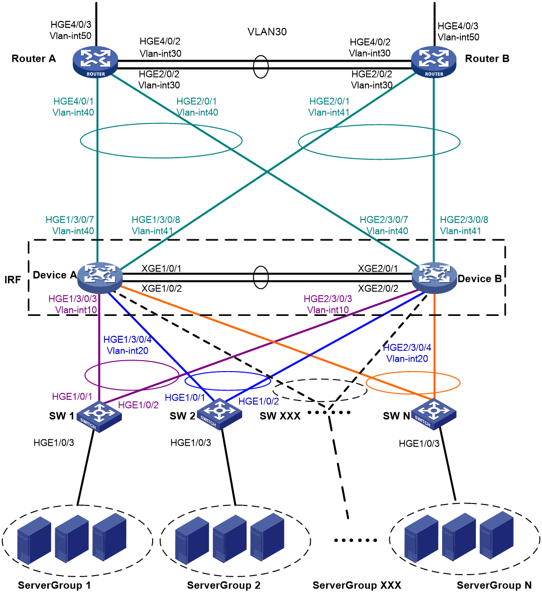
Table 2 VLAN and IP address assignment
|
Device |
VLAN interface |
IP address |
|
Router A |
VLAN-interface 30 |
172.24.2.2/24 |
|
Router A |
VLAN-interface 40 |
172.24.40.2/24 |
|
Router A |
VLAN-interface 50 |
172.24.1.2/24 |
|
Router B |
VLAN-interface 30 |
172.24.2.3/24 |
|
Router B |
VLAN-interface 41 |
172.24.41.3/24 |
|
Router B |
VLAN-interface 50 |
172.24.4.3/24 |
|
IRF fabric |
VLAN-interface 10 |
172.24.10.254/24 |
|
IRF fabric |
VLAN-interface 20 |
172.24.20.254/24 |
|
IRF fabric |
VLAN-interface 40 |
172.24.40.254/24 |
|
IRF fabric |
VLAN-interface 41 |
172.24.41.254/24 |
Applicable hardware and software versions
The following matrix shows the hardware and software versions to which this configuration example is applicable:
|
Hardware |
Software version |
|
S12500G-AF switch series |
Release 7639P01 and later |
|
S10500X switch series |
Release 7639P01 and later |
|
S10500 switch series |
Release 7639P01 and later |
|
S7500E-X switch series |
Release 7639P01 and later |
|
S7500E switch series |
Release 7639P01 and later |
|
S7500X switch series |
Release 7639P01 and later |
Restrictions and guidelines
To avoid single points of failure, use multichassis link aggregations to connect the IRF fabric to the downstream and upstream devices.
You do not need to run LACP MAD on all link aggregations. You can detect IRF split effectively by running LACP MAD on one dynamic link aggregation.
For LACP MAD to run correctly, ensure that the intermediate device can recognize and process extended LACPDUs that contain the ActiveID field for LACP MAD.
When you configure LACP MAD on a link aggregation, follow these restrictions and guidelines:
· The link aggregation must use dynamic aggregation mode.
· The link aggregation must have a minimum of one member link from each member chassis.
· If the intermediate device is also an IRF fabric, you must assign the two IRF fabrics different domain IDs for correct split detection.
Procedures
Setting up the IRF fabric
1. Configure Device A:
# Assign member ID 1 to Device A.
<DeviceA> system-view
[DeviceA] irf member 1
# Bind Ten-GigabitEthernet 1/0/1 and Ten-GigabitEthernet 1/0/2 to IRF-port 2.
[DeviceA] irf-port 2
[DeviceA-irf-port2] port group interface ten-gigabitEthernet1/0/1
[DeviceA-irf-port2] port group interface ten-gigabitEthernet1/0/2
[DeviceA-irf-port2] quit
# Save the running configuration to the main next-startup configuration file before changing the operating mode to IRF.
|
|
IMPORTANT: The mode change requires a system reboot. The save operation prevents loss of unsaved settings on reboot. |
[DeviceA] save
# Enable IRF mode.
[DeviceA] chassis convert mode irf
The device will switch to IRF mode and reboot. Continue? [Y/N]:y
You are recommended to save the current running configuration and specify the configuration file for the next startup. Continue? [Y/N]:y
Do you want to convert the content of the next startup configuration file cfa0:/
irf.cfg to make it available in stack mode? [Y/N]:y
Now rebooting, please wait...
2. Configure Device B:
# Assign member ID 2 to Device B.
<DeviceB> system-view
[DeviceB] irf member 2
# Bind Ten-GigabitEthernet 2/0/1 and Ten-GigabitEthernet 2/0/2 to IRF-port 1.
[DeviceB] irf-port 1
[DeviceB-irf-port1] port group interface ten-gigabitEthernet2/0/1
[DeviceB-irf-port1] port group interface ten-gigabitEthernet2/0/2
[DeviceB-irf-port1] quit
# Save the configuration.
[DeviceB] save
# Connect IRF-port 2 on Device A to IRF-port 1 on Device B, as shown in Figure 3.
# Enable IRF mode.
[DeviceB] chassis convert mode irf
The device will switch to IRF mode and reboot. Continue? [Y/N]:y
You are recommended to save the current running configuration and specify the configuration file for the next startup. Continue? [Y/N]:y
Do you want to convert the content of the next startup configuration file cfa0:/
irf.cfg to make it available in stack mode? [Y/N]:y
Now rebooting, please wait...
Configuring software features
This example provides only basic software settings.
Configuring the IRF fabric
After the IRF fabric is formed, the master's system name becomes the fabric's system name. You can configure software features on the fabric as you do on a standalone device.
1. Configure link aggregations:
# Create a Layer 2 dynamic aggregate interface Bridge-Aggregation 1. Enable LACP MAD on the aggregate interface.
<DeviceA> system-view
[DeviceA] interface bridge-aggregation 1
[DeviceA-Bridge-Aggregation1] link-aggregation mode dynamic
[DeviceA-Bridge-Aggregation1] mad enable
You need to assign a domain ID (range: 0-4294967295)
[Current domain is: 0]:
The assigned domain ID is: 0
[DeviceA-Bridge-Aggregation1] quit
# Assign the downlink ports connected to SW 1 to the aggregation group of Bridge-Aggregation 1.
[DeviceA] interface hundredgige 1/3/0/3
[DeviceA-HundredGigE1/3/0/3] port link-aggregation group 1
[DeviceA-HundredGigE1/3/0/3] quit
[DeviceA] interface hundredgige 2/3/0/3
[DeviceA-HundredGigE2/3/0/3] port link-aggregation group 1
[DeviceA-HundredGigE2/3/0/3] quit
# Create Bridge-Aggregation 2. Assign the downlink ports connected to SW 2 to the aggregation group.
[DeviceA] interface bridge-aggregation 2
[DeviceA-Bridge-Aggregation2] quit
[DeviceA] interface hundredgige 1/3/0/4
[DeviceA-HundredGigE1/3/0/4] port link-aggregation group 2
[DeviceA-HundredGigE1/3/0/4] quit
[DeviceA] interface hundredgige 2/3/0/4
[DeviceA-HundredGigE2/3/0/4] port link-aggregation group 2
[DeviceA-HundredGigE2/3/0/4] quit
# Create Bridge-Aggregation 1023. Assign the uplink ports connected to Router A to Bridge-Aggregation 1023.
[DeviceA] interface bridge-aggregation 1023
[DeviceA-Bridge-Aggregation1023] quit
[DeviceA] interface hundredgige 1/3/0/7
[DeviceA-HundredGigE1/3/0/7] port link-aggregation group 1023
[DeviceA-HundredGigE1/3/0/7] quit
[DeviceA] interface hundredgige 2/3/0/7
[DeviceA-HundredGigE2/3/0/7] port link-aggregation group 1023
[DeviceA-HundredGigE2/3/0/7] quit
# Create Bridge-Aggregation 1024. Assign the uplink ports connected to Router B to Bridge-Aggregation 1024.
[DeviceA] interface bridge-aggregation 1024
[DeviceA-Bridge-Aggregation1024] quit
[DeviceA] interface hundredgige 1/3/0/8
[DeviceA-HundredGigE1/3/0/8] port link-aggregation group 1024
[DeviceA-HundredGigE1/3/0/8] quit
[DeviceA] interface hundredgige 2/3/0/8
[DeviceA-HundredGigE2/3/0/8] port link-aggregation group 1024
[DeviceA-HundredGigE2/3/0/8] quit
2. Configure VLANs, ports, and IP addresses:
# Create VLAN 10, assign an IP address to VLAN-interface 10, and assign Bridge-Aggregation 1 to VLAN 10.
[DeviceA] vlan 10
[DeviceA-vlan10] quit
[DeviceA] interface vlan-interface 10
[DeviceA-Vlan-interface10] ip address 172.24.10.254 24
[DeviceA-Vlan-interface10] quit
[DeviceA] interface bridge-aggregation 1
[DeviceA-Bridge-Aggregation1] port link-type trunk
[DeviceA-Bridge-Aggregation1] undo port trunk permit vlan 1
[DeviceA-Bridge-Aggregation1] port trunk permit vlan 10
[DeviceA-Bridge-Aggregation1] quit
# Create VLAN 20, assign an IP address to VLAN-interface 20, and assign Bridge-Aggregation 2 to VLAN 20.
[DeviceA] vlan 20
[DeviceA-vlan20] quit
[DeviceA] interface vlan-interface 20
[DeviceA-Vlan-interface20] ip address 172.24.20.254 24
[DeviceA-Vlan-interface20] quit
[DeviceA] interface bridge-aggregation 2
[DeviceA-Bridge-Aggregation2] port link-type trunk
[DeviceA-Bridge-Aggregation2] undo port trunk permit vlan 1
[DeviceA-Bridge-Aggregation2] port trunk permit vlan 20
[DeviceA-Bridge-Aggregation2] quit
# Create VLAN 40, assign an IP address to VLAN-interface 40, and assign Bridge-Aggregation 1023 to VLAN 40.
[DeviceA] vlan 40
[DeviceA-vlan40] quit
[DeviceA] interface vlan-interface 40
[DeviceA-Vlan-interface40] ip address 172.24.40.254 24
[DeviceA-Vlan-interface40] quit
[DeviceA] interface bridge-aggregation 1023
[DeviceA-Bridge-Aggregation1023] port access vlan 40
[DeviceA-Bridge-Aggregation1023] quit
# Create VLAN 41, assign an IP address to VLAN-interface 41, and assign Bridge-Aggregation 1024 to VLAN 41.
[DeviceA] vlan 41
[DeviceA-vlan41] quit
[DeviceA] interface vlan-interface 41
[DeviceA-Vlan-interface41] ip address 172.24.41.254 24
[DeviceA-Vlan-interface41] quit
[DeviceA] interface bridge-aggregation 1024
[DeviceA-Bridge-Aggregation1024] port access vlan 41
[DeviceA-Bridge-Aggregation1024] quit
3. Configure OSPF between the IRF fabric and the egress routers.
[DeviceA] ospf
[DeviceA-ospf-1] import-route direct
[DeviceA-ospf-1] area 0
[DeviceA-ospf-1-area-0.0.0.0] network 172.24.40.0 0.0.0.255
[DeviceA-ospf-1-area-0.0.0.0] network 172.24.41.0 0.0.0.255
[DeviceA-ospf-1-area-0.0.0.0] quit
[DeviceA-ospf-1] quit
Configuring SW 1
1. Configure a link aggregation:
# Create Bridge-Aggregation 1 and enable the dynamic aggregation mode. You must enable the dynamic aggregation mode because this link aggregation will be used for LACP MAD.
<SW1> system-view
[SW1] interface bridge-aggregation 1
[SW1-Bridge-Aggregation1] link-aggregation mode dynamic
[SW1-Bridge-Aggregation1] quit
# Assign the uplink ports connected to the IRF fabric to Bridge-Aggregation 1.
[SW1] interface hundredgige 1/0/1
[SW1-HundredGigE1/0/1] port link-aggregation group 1
[SW1-HundredGigE1/0/1] quit
[SW1] interface hundredgige 1/0/2
[SW1-HundredGigE1/0/2] port link-aggregation group 1
[SW1-HundredGigE1/0/2] quit
2. Configure VLANs, ports, and IP addresses:
# Create all VLANs.
[SW1] vlan all
# Configure VLAN settings on the uplink aggregate interface connected to the IRF fabric.
[SW1] interface bridge-aggregation 1
[SW1-Bridge-Aggregation1] port link-type trunk
[SW1-Bridge-Aggregation1] undo port trunk permit vlan 1
[SW1-Bridge-Aggregation1] port trunk permit vlan 10
[SW1-Bridge-Aggregation1] quit
# Configure VLAN settings on the port connected to Server Group 1.
[SW1] interface hundredgige 1/0/3
[SW1-HundredGigE1/0/3] port link-type trunk
[SW1-HundredGigE1/0/3] port trunk permit vlan all
[SW1-HundredGigE1/0/3] undo port trunk permit vlan 1
[SW1-HundredGigE1/0/3] quit
Configuring SW 2
1. Configure a link aggregation:
# Create Bridge-Aggregation 1.
<SW2> system-view
[SW2] interface bridge-aggregation 1
[SW2-Bridge-Aggregation1] quit
# Assign the uplink ports connected to the IRF fabric to Bridge-Aggregation 1.
[SW2] interface hundredgige 1/0/1
[SW2-HundredGigE1/0/1] port link-aggregation group 1
[SW2-HundredGigE1/0/1] quit
[SW2] interface hundredgige 1/0/2
[SW2-HundredGigE1/0/2] port link-aggregation group 1
[SW2-HundredGigE1/0/2] quit
2. Configure VLANs, ports, and IP addresses:
# Create all VLANs.
[SW2] vlan all
# Configure VLAN settings on the uplink aggregate interface connected to the IRF fabric.
[SW2] interface bridge-aggregation 1
[SW2-Bridge-Aggregation1] port link-type trunk
[SW2-Bridge-Aggregation1] undo port trunk permit vlan 1
[SW2-Bridge-Aggregation1] port trunk permit vlan 20
[SW2-Bridge-Aggregation1] quit
# Configure VLAN settings on the port connected to Server Group 2.
[SW2] interface hundredgige 1/0/3
[SW2-HundredGigE1/0/3] port link-type trunk
[SW2-HundredGigE1/0/3] port trunk permit vlan all
[SW2-HundredGigE1/0/3] undo port trunk permit vlan 1
[SW2-HundredGigE1/0/3] quit
Configuring Router A
In this example, the egress router configuration only includes the connection to the IRF fabric.
1. Configure link aggregations:
# Create Bridge-Aggregation 1. Assign the downlink ports connected to the IRF fabric to Bridge-Aggregation 1.
<RouterA> system-view
[RouterA] interface bridge-aggregation 1
[RouterA-Bridge-Aggregation1] quit
[RouterA] interface hundredgige 4/0/1
[RouterA-HundredGigE4/0/1] port link-mode bridge
[RouterA-HundredGigE4/0/1] port link-aggregation group 1
[RouterA-HundredGigE4/0/1] quit
[RouterA] interface hundredgige 2/0/1
[RouterA-HundredGigE2/0/1] port link-mode bridge
[RouterA-HundredGigE2/0/1] port link-aggregation group 1
[RouterA-HundredGigE2/0/1] quit
# Create Bridge-Aggregation 2. Assign the ports connected to Router B to Bridge-Aggregation 2.
[RouterA] interface bridge-aggregation 2
[RouterA-Bridge-Aggregation2] quit
[RouterA] interface hundredgige 4/0/2
[RouterA-HundredGigE4/0/2] port link-mode bridge
[RouterA-HundredGigE4/0/2] port link-aggregation group 2
[RouterA-HundredGigE4/0/2] quit
[RouterA] interface hundredgige 2/0/2
[RouterA-HundredGigE2/0/2] port link-mode bridge
[RouterA-HundredGigE2/0/2] port link-aggregation group 2
[RouterA-HundredGigE2/0/2] quit
2. Configure VLANs, ports, and IP addresses:
# Create VLAN 40, assign an IP address to VLAN-interface 40, and assign Bridge-Aggregation 1 to VLAN 40.
[RouterA] vlan 40
[RouterA-vlan40] quit
[RouterA] interface vlan-interface 40
[RouterA-vlan-interface40] ip address 172.24.40.2 24
[RouterA-vlan-interface40] quit
[RouterA] interface bridge-aggregation 1
[RouterA-Bridge-Aggregation1] port access vlan 40
[RouterA-Bridge-Aggregation1] quit
# Create VLAN 30, assign an IP address to VLAN-interface 30, and assign Bridge-Aggregation 2 to VLAN 30.
[RouterA] vlan 30
[RouterA-vlan30] quit
[RouterA] interface vlan-interface 30
[RouterA-vlan-interface30] ip address 172.24.2.2 24
[RouterA-vlan-interface30] quit
[RouterA] interface bridge-aggregation 2
[RouterA-Bridge-Aggregation2] port link-type access
[RouterA-Bridge-Aggregation2] port access vlan 30
[RouterA-Bridge-Aggregation2] quit
# Create VLAN 50, assign an IP address to VLAN-interface 50, and assign HundredGigE 4/0/3 to VLAN 50.
[RouterA] vlan 50
[RouterA-vlan50] quit
[RouterA] interface vlan-interface 50
[RouterA-vlan-interface50] ip address 172.24.1.2 24
[RouterA-vlan-interface50] quit
[RouterA] interface hundredgige 4/0/3
[RouterA-HundredGigE4/0/3] port link-mode bridge
[RouterA-HundredGigE4/0/3] port access vlan 50
[RouterA-HundredGigE4/0/3] quit
3. Configure OSPF between Router A and the IRF fabric.
[RouterA] ospf
[RouterA-ospf-1] import-route direct
[RouterA-ospf-1] area 0
[RouterA-ospf-1-area-0.0.0.0] network 172.24.40.0 0.0.0.255
[RouterA-ospf-1-area-0.0.0.0] network 172.24.2.0 0.0.0.255
[RouterA-ospf-1-area-0.0.0.0] quit
[RouterA-ospf-1] quit
Configuring Router B
In this example, the egress router configuration only includes the connection to the IRF fabric.
1. Configure link aggregations:
# Create Bridge-Aggregation 1. Assign the downlink ports connected to the IRF fabric to Bridge-Aggregation 1.
<RouterB> system-view
[RouterB] interface bridge-aggregation 1
[RouterB-Bridge-Aggregation1] quit
[RouterB] interface hundredgige 4/0/1
[RouterB-HundredGigE4/0/1] port link-mode bridge
[RouterB-HundredGigE4/0/1] port link-aggregation group 1
[RouterB-HundredGigE4/0/1] quit
[RouterB] interface hundredgige 2/0/1
[RouterB-HundredGigE2/0/1] port link-mode bridge
[RouterB-HundredGigE2/0/1] port link-aggregation group 1
[RouterB-HundredGigE2/0/1] quit
# Create Bridge-Aggregation 2. Assign the ports connected to Router A to Bridge-Aggregation 2.
[RouterB] interface bridge-aggregation 2
[RouterB-Bridge-Aggregation2] quit
[RouterB] interface hundredgige 4/0/2
[RouterB-HundredGigE4/0/2] port link-mode bridge
[RouterB-HundredGigE4/0/2] port link-aggregation group 2
[RouterB-HundredGigE4/0/2] quit
[RouterB] interface hundredgige 2/0/2
[RouterB-HundredGigE2/0/2] port link-mode bridge
[RouterB-HundredGigE2/0/2] port link-aggregation group 2
[RouterB-HundredGigE2/0/2] quit
2. Configure VLANs, ports, and IP addresses:
# Create VLAN 41, assign an IP address to VLAN-interface 41, and assign Bridge-Aggregation 1 to VLAN 41.
[RouterB] vlan 41
[RouterB-vlan41] quit
[RouterB] interface vlan-interface 41
[RouterB-vlan-interface41] ip address 172.24.41.3 24
[RouterB-vlan-interface41] quit
[RouterB] interface bridge-aggregation 1
[RouterB-Bridge-Aggregation1] port access vlan 41
[RouterB-Bridge-Aggregation1] quit
# Create VLAN 30, assign an IP address to VLAN-interface 30, and assign Bridge-Aggregation 2 to VLAN 30.
[RouterB] vlan 30
[RouterB-vlan30] quit
[RouterB] interface vlan-interface 30
[RouterB-vlan-interface30] ip address 172.24.2.3 24
[RouterB-vlan-interface30] quit
[RouterB] interface bridge-aggregation 2
[RouterB-Bridge-Aggregation2] port link-type access
[RouterB-Bridge-Aggregation2] port access vlan 30
[RouterB-Bridge-Aggregation2] quit
# Create VLAN 50, assign an IP address to VLAN-interface 50, and assign HundredGigE 4/0/3 to VLAN 50.
[RouterB] vlan 50
[RouterB-vlan50] quit
[RouterB] interface vlan-interface 50
[RouterB-vlan-interface50] ip address 172.24.4.3 24
[RouterB-vlan-interface50] quit
[RouterB] interface hundredgige 4/0/3
[RouterB-HundredGigE4/0/3] port link-mode bridge
[RouterB-HundredGigE4/0/3] port access vlan 50
[RouterB-HundredGigE4/0/3] quit
3. Configure OSPF between Router B and the IRF fabric.
[RouterB] ospf
[RouterB-ospf-1] import-route direct
[RouterB-ospf-1] area 0
[RouterB-ospf-1-area-0.0.0.0] network 172.24.41.0 0.0.0.255
[RouterB-ospf-1-area-0.0.0.0] network 172.24.2.0 0.0.0.255
[RouterB-ospf-1-area-0.0.0.0] quit
[RouterB-ospf-1] quit
Verifying the configuration
Verify that the IRF fabric, multichassis link aggregation configuration, and IRF link redundancy operate correctly.
Verifying the IRF function
# Execute the display irf command in any view.
[DeviceA] display irf
MemberID Slot Role Priority CPU-Mac Description
*+1 0 Master 1 0210-fc01-0000 ---
2 0 Standby 1 0210-fc02-0000 ---
--------------------------------------------------
* indicates the device is the master.
+ indicates the device through which the user logs in.
The Bridge MAC of the IRF is: 3822-d60f-2800
Auto upgrade : yes
Mac persistent : always
Domain ID : 0
Auto merge : yes
IRF mode : normal
The command output shows that the member chassis have formed an IRF fabric.
Verifying the link backup function of multichassis aggregations
# Shut down HundredGigE 1/3/0/8, the port connected to the egress router.
[DeviceA] interface hundredgige 1/3/0/8
[DeviceA-HundredGigE1/3/0/8] shutdown
# Ping an IP address on the public network from a PC in Server Group 1.
C:\Users>ping 202.108.22.5 -t
Pinging 202.108.22.5 with 32 bytes of data:
Reply from 202.108.22.5: bytes=32 time=1ms TTL=122
Reply from 202.108.22.5: bytes=32 time=13ms TTL=122
Reply from 202.108.22.5: bytes=32 time<1ms TTL=122
Request timed out.
Request timed out.
Request timed out.
Reply from 202.108.22.5: bytes=32 time<1ms TTL=122
Reply from 202.108.22.5: bytes=32 time<1ms TTL=122
Reply from 202.108.22.5: bytes=32 time<1ms TTL=122
The output shows that the address can be pinged after transient traffic disruption.
# Bring up HundredGigE 1/3/0/8 and shut down HundredGigE 2/3/0/8.
[DeviceA-HundredGigE1/3/0/8] undo shutdown
[DeviceA-HundredGigE1/3/0/8] quit
[DeviceA] interface hundredgige 2/3/0/8
[DeviceA-HundredGigE2/3/0/8] shutdown
# Ping the IP address on the public network from the PC.
C:\Users>ping 202.108.22.5 -t
Pinging 202.108.22.5 with 32 bytes of data:
Reply from 202.108.22.5: bytes=32 time=1ms TTL=122
Reply from 202.108.22.5: bytes=32 time=13ms TTL=122
Reply from 202.108.22.5: bytes=32 time<1ms TTL=122
Request timed out.
Request timed out.
Request timed out.
Reply from 202.108.22.5: bytes=32 time<1ms TTL=122
Reply from 202.108.22.5: bytes=32 time<1ms TTL=122
Reply from 202.108.22.5: bytes=32 time<1ms TTL=122
The output shows that the address can be pinged after transient traffic disruption.
Verifying the link backup function of IRF connections
Verify that the IRF fabric is integrated and can forward traffic across member chassis after one IRF connection cable is removed.
Configuration files
IRF fabric
#
irf mac-address persistent always
irf auto-update enable
irf auto-merge enable
undo irf link-delay
irf member 1 priority 1
irf member 2 priority 1
#
ospf 1
import-route direct
area 0.0.0.0
network 172.24.40.0 0.0.0.255
network 172.24.41.0 0.0.0.255
#
vlan 10
#
vlan 20
#
vlan 40
#
vlan 41
#
irf-port 1/2
port group interface HundredGigE1/2/0/1 mode enhanced
port group interface HundredGigE1/3/0/1 mode enhanced
#
irf-port 2/1
port group interface HundredGigE2/2/0/1 mode enhanced
port group interface HundredGigE2/3/0/1 mode enhanced
#
interface bridge-aggregation 1
port link-type trunk
undo port trunk permit vlan 1
port trunk permit vlan 10
link-aggregation mode dynamic
mad enable
#
interface bridge-aggregation 2
port link-type trunk
undo port trunk permit vlan 1
port trunk permit vlan 20
#
interface bridge-aggregation 1023
port access vlan 40
#
interface bridge-aggregation 1024
port access vlan 41
#
interface vlan-interface 10
ip address 172.24.10.254 255.255.255.0
#
interface vlan-interface 20
ip address 172.24.20.254 255.255.255.0
#
interface vlan-interface 40
ip address 172.24.40.254 255.255.255.0
#
interface HundredGigE 1/3/0/3
port link-mode bridge
port link-type trunk
undo port trunk permit vlan 1
port trunk permit vlan 10
port link-aggregation group 1
#
interface HundredGigE 1/3/0/4
port link-mode bridge
port link-type trunk
undo port trunk permit vlan 1
port trunk permit vlan 20
port link-aggregation group 2
#
interface HundredGigE 1/3/0/7
port link-mode bridge
port access vlan 40
port link-aggregation group 1023
#
interface HundredGigE 1/3/0/8
port link-mode bridge
port access vlan 41
port link-aggregation group 1024
#
interface HundredGigE 2/3/0/3
port link-mode bridge
port link-type trunk
undo port trunk permit vlan 1
port trunk permit vlan 10
port link-aggregation group 1
#
interface HundredGigE 2/3/0/4
port link-mode bridge
port link-type trunk
undo port trunk permit vlan 1
port trunk permit vlan 20
port link-aggregation group 2
#
interface HundredGigE 2/3/0/7
port link-mode bridge
port access vlan 40
port link-aggregation group 1023
#
interface HundredGigE 2/3/0/8
port link-mode bridge
port access vlan 41
port link-aggregation group 1024
#
SW 1
#
vlan 10
#
interface bridge-aggregation 1
port link-type trunk
undo port trunk permit vlan 1
port trunk permit vlan 10
link-aggregation mode dynamic
#
interface HundredGigE 1/0/1
port link-mode bridge
port link-type trunk
undo port trunk permit vlan 1
port trunk permit vlan 10
port link-aggregation group 1
#
interface HundredGigE 1/0/2
port link-mode bridge
port link-type trunk
undo port trunk permit vlan 1
port trunk permit vlan 10
port link-aggregation group 1
#
interface HundredGigE 1/0/3
port link-mode bridge
port link-type trunk
undo port trunk permit vlan 1
port trunk permit vlan 2 to 4094
#
SW 2
#
vlan 20
#
interface bridge-aggregation 1
port link-type trunk
undo port trunk permit vlan 1
port trunk permit vlan 20
#
interface HundredGigE 1/0/1
port link-mode bridge
port link-type trunk
undo port trunk permit vlan 1
port trunk permit vlan 20
port link-aggregation group 1
#
interface HundredGigE 1/0/2
port link-mode bridge
port link-type trunk
undo port trunk permit vlan 1
port trunk permit vlan 20
port link-aggregation group 1
#
interface HundredGigE 1/0/3
port link-mode bridge
port link-type trunk
undo port trunk permit vlan 1
port trunk permit vlan 2 to 4094
#
Router A
#
ospf 1
import-route direct
area 0.0.0.0
network 172.24.2.0 0.0.0.255
network 172.24.40.0 0.0.0.255
#
vlan 30
#
vlan 40
#
vlan 50
#
interface bridge-aggregation 1
port access vlan 40
#
interface bridge-aggregation 2
port access vlan 30
#
interface vlan-interface 30
ip address 172.24.2.2 255.255.255.0
#
interface vlan-interface 40
ip address 172.24.40.2 255.255.255.0
#
interface vlan-interface 50
ip address 172.24.1.2 255.255.255.0
#
interface HundredGigE 2/0/1
port link-mode bridge
port access vlan 40
port link-aggregation group 1
#
interface HundredGigE 2/0/2
port link-mode bridge
port access vlan 30
port link-aggregation group 2
#
interface HundredGigE 4/0/1
port link-mode bridge
port access vlan 40
port link-aggregation group 1
#
interface HundredGigE 4/0/2
port link-mode bridge
port access vlan 30
port link-aggregation group 2
#
interface HundredGigE 4/0/3
port link-mode bridge
port access vlan 50
#
Router B
#
ospf 1
import-route direct
area 0.0.0.0
network 172.24.2.0 0.0.0.255
network 172.24.41.0 0.0.0.255
#
vlan 30
#
vlan 41
#
vlan 50
#
interface bridge-aggregation 1
port access vlan 41
#
interface bridge-aggregation 2
port access vlan 30
#
interface vlan-interface 30
ip address 172.24.2.3 255.255.255.0
#
interface vlan-interface 41
ip address 172.24.41.3 255.255.255.0
#
interface vlan-interface 50
ip address 172.24.4.3 255.255.255.0
#
interface HundredGigE 2/0/1
port link-mode bridge
port access vlan 41
port link-aggregation group 1
#
interface HundredGigE 2/0/2
port link-mode bridge
port access vlan 30
port link-aggregation group 2
#
interface HundredGigE 4/0/1
port link-mode bridge
port access vlan 41
port link-aggregation group 1
#
interface HundredGigE 4/0/2
port link-mode bridge
port access vlan 30
port link-aggregation group 2
#
interface HundredGigE 4/0/3
port link-mode bridge
port access vlan 50
#
Example: Setting up a LACP MAD-enabled four-chassis IRF fabric
Network configuration
As shown in Figure 4:
· Set up a four-chassis IRF fabric at the core layer of the network.
· Use multichassis link aggregations to connect the IRF fabric to the access switches and the upstream egress routers. Make sure that Router A is not disconnected from the switches at the distribution layer (for example, SW 1 and SW 2) even if up to three chassis fail in the IRF fabric.
· Use LACP MAD to detect IRF split.
· Run OSPF between the IRF fabric and the egress routers.
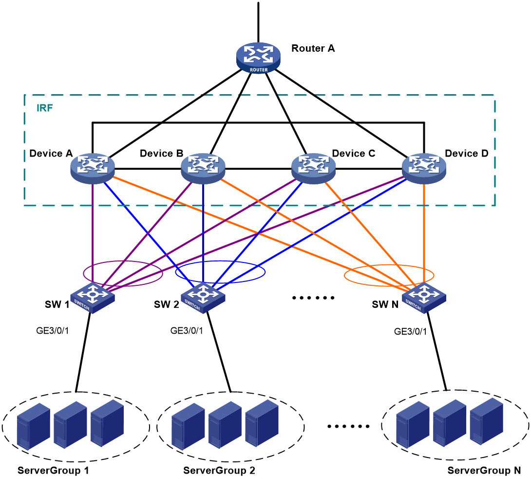
Table 3 VLAN and IP address assignment
|
Device |
VLAN interface |
IP address |
|
Router A |
VLAN-interface 41 |
172.24.41.2/24 |
|
VLAN-interface 50 |
172.24.1.2/24 |
|
|
IRF fabric |
VLAN-interface 41 |
172.24.41.254/24 |
|
VLAN-interface 10 |
172.24.10.254/24 |
|
|
VLAN-interface 20 |
172.24.20.254/24 |
|
|
… |
… |
|
|
VLAN-interface N |
172.24.N.254/24 |
Table 4 IRF links
|
Device |
Local IRF port |
Peer IRF port |
IRF member port |
|
Device A |
irf-port 1/1 |
irf-port 4/2 |
XGE1/0/1 |
|
Device A |
irf-port 1/2 |
irf-port 2/1 |
XGE1/0/2 |
|
Device B |
irf-port 2/1 |
irf-port 1/2 |
XGE2/0/1 |
|
Device B |
irf-port 2/2 |
irf-port 3/1 |
XGE2/0/2 |
|
Device C |
irf-port 3/1 |
irf-port 2/2 |
XGE3/0/1 |
|
Device C |
irf-port 3/2 |
irf-port 4/1 |
XGE3/0/2 |
|
Device D |
irf-port 4/1 |
irf-port 3/2 |
XGE4/0/1 |
|
Device D |
irf-port 4/2 |
irf-port 1/1 |
XGE4/0/2 |
Table 5 Uplinks and downlinks of the IRF device
|
Peer device |
Interface |
VLAN |
Aggregation group |
|
SW 2 at the downstream |
XGE1/3/0/1 |
VLAN 13 (BFD MAD) |
|
|
SW 2 at the downstream |
XGE2/3/0/1 |
VLAN 13 (BFD MAD) |
|
|
SW 2 at the downstream |
XGE3/3/0/1 |
VLAN 13 (BFD MAD) |
|
|
SW 2 at the downstream |
XGE4/3/0/1 |
VLAN 13 (BFD MAD) |
|
|
XGE1/3/0/3 |
VLAN 10 |
Bridge-aggregation 1 (LACP MAD) |
|
|
SW 1 at the downstream |
XGE2/3/0/3 |
VLAN 10 |
Bridge-aggregation 1 (LACP MAD) |
|
SW 1 at the downstream |
XGE3/3/0/3 |
VLAN 10 |
Bridge-aggregation 1 (LACP MAD) |
|
SW 1 at the downstream |
XGE4/3/0/3 |
VLAN 10 |
Bridge-aggregation 1 (LACP MAD) |
|
SW 2 at the downstream |
XGE1/3/0/4 |
VLAN 20 |
Bridge-aggregation 2 |
|
SW 2 at the downstream |
XGE2/3/0/4 |
VLAN 20 |
Bridge-aggregation 2 |
|
SW 2 at the downstream |
XGE3/3/0/4 |
VLAN 20 |
Bridge-aggregation 2 |
|
SW 2 at the downstream |
XGE4/3/0/4 |
VLAN 20 |
Bridge-aggregation 2 |
|
Router A at the upstream |
XGE1/3/0/8 |
VLAN 41 |
Bridge-aggregation 1024 |
|
Router A at the upstream |
XGE2/3/0/8 |
VLAN 41 |
Bridge-aggregation 1024 |
|
Router A at the upstream |
XGE3/3/0/8 |
VLAN 41 |
Bridge-aggregation 1024 |
|
Router A at the upstream |
XGE4/3/0/8 |
VLAN 41 |
Bridge-aggregation 1024 |
Table 6 Uplinks and downlinks of SW 1
|
Peer device |
Interface |
VLAN |
Aggregation group |
|
Service group at the downstream |
GE3/0/1 |
VLAN 10 |
|
|
XGE2/0/21 |
VLAN 10 |
Bridge-aggregation 1 (LACP MAD) |
|
|
IRF fabric at the upstream |
XGE2/0/22 |
VLAN 10 |
Bridge-aggregation 1 (LACP MAD) |
|
IRF fabric at the upstream |
XGE2/0/23 |
Bridge-aggregation 1 (LACP MAD) |
|
|
IRF fabric at the upstream |
XGE2/0/24 |
VLAN 10 |
Bridge-aggregation 1 (LACP MAD) |
Table 7 Uplinks and downlinks of SW 2
|
Peer device |
Interface |
VLAN |
Aggregation group |
|
Service group at the downstream |
GE3/0/1 |
VLAN 20 |
|
|
IRF fabric at the upstream |
XGE2/0/21 |
VLAN 20 |
Bridge-aggregation 1 |
|
IRF fabric at the upstream |
XGE2/0/22 |
VLAN 20 |
Bridge-aggregation 1 |
|
IRF fabric at the upstream |
XGE2/0/23 |
VLAN 20 |
Bridge-aggregation 1 |
|
IRF fabric at the upstream |
XGE2/0/24 |
VLAN 20 |
Bridge-aggregation 1 |
Table 8 Uplinks and downlinks of Router A
|
Peer device |
Interface |
VLAN |
Aggregation group |
|
IRF fabric at the downstream |
XGE2/0/1 |
VLAN 41 |
Bridge-aggregation 1 |
|
IRF fabric at the downstream |
XGE2/0/2 |
VLAN n 41 |
Bridge-aggregation 1 |
|
IRF fabric at the downstream |
XGE2/0/3 |
VLAN 41 |
Bridge-aggregation 1 |
|
IRF fabric at the downstream |
XGE2/0/4 |
VLAN 41 |
Bridge-aggregation 1 |
|
External network at the upstream |
XGE2/0/2 |
VLAN 50 |
|
Restrictions and guidelines
To avoid single points of failure, use multichassis link aggregations to connect the IRF fabric to the downstream and upstream devices.
You do not need to run LACP MAD on all link aggregations. You can detect IRF split effectively by running LACP MAD on one dynamic link aggregation.
For LACP MAD to run correctly, ensure that the intermediate device can recognize and process extended LACPDUs that contain the ActiveID field for LACP MAD.
When you configure LACP MAD on a link aggregation, follow these restrictions and guidelines:
· The link aggregation must use dynamic aggregation mode.
· The link aggregation must have a minimum of one member link from each member chassis.
· If the intermediate device is also an IRF fabric, you must assign the two IRF fabrics different domain IDs for correct split detection.
Applicable hardware and software versions
The following matrix shows the hardware and software versions to which this configuration example is applicable:
|
Hardware |
Software version |
|
S12500G-AF switch series |
Release 7639P01 and later |
|
S10500X switch series |
Release 7639P01 and later |
|
S10500 switch series |
Release 7639P01 and later |
|
S7500E-X switch series |
Release 7639P01 and later |
|
S7500E switch series |
Release 7639P01 and later |
|
S7500X switch series |
Release 7639P01 and later |
Procedures
Setting up the IRF fabric
1. Configure Device A:
# Assign member ID 1 to Device A.
<DeviceA> system-view
[DeviceA] irf member 1
# Bind Ten-GigabitEthernet 1/0/1 to IRF-port 1.
[DeviceA] irf-port 1
[DeviceA-irf-port1] port group interface ten-gigabitethernet 1/0/1
[DeviceA-irf-port1] quit
# Bind Ten-GigabitEthernet 1/0/2 to IRF-port 2.
[DeviceA] irf-port 2
[DeviceA-irf-port2] port group interface ten-gigabitethernet 1/0/2
[DeviceA-irf-port2] quit
# Save the running configuration to the main next-startup configuration file before changing the operating mode to IRF.
|
|
IMPORTANT: The mode change requires a system reboot. The save operation prevents loss of unsaved settings on reboot. |
[DeviceA] save
The current configuration will be written to the device. Are you sure? [Y/N]:y
Please input the file name(*.cfg)[cfa0:/irf.cfg]
(To leave the existing filename unchanged, press the enter key):
cfa0:/irf.cfg exists, overwrite? [Y/N]:y
Validating file. Please wait.....................................
Saved the current configuration to mainboard device successfully.
# Enable IRF mode.
[DeviceA] chassis convert mode irf
The device will switch to IRF mode and reboot. Continue? [Y/N]:y
You are recommended to save the current running configuration and specify the c
onfiguration file for the next startup. Continue? [Y/N]:y
Do you want to convert the content of the next startup configuration file flash
:/startup.cfg to make it available in stack mode? [Y/N]:y
Now rebooting, please wait...
2. Configure Device B:
# Assign member ID 2 to Device B.
<DeviceB> system-view
[DeviceB] irf member 2
# Bind Ten-GigabitEthernet 2/0/1 to IRF-port 1.
[DeviceB] irf-port 1
[DeviceB-irf-port1] port group interface ten-gigabitethernet 2/0/1
[DeviceB-irf-port1] quit
# Bind Ten-GigabitEthernet 2/0/2 to IRF-port 2.
[DeviceB] irf-port 2
[DeviceB-irf-port2] port group interface ten-gigabitethernet 2/0/2
[DeviceB-irf-port2] quit
# Save the configuration.
[DeviceB] save
The current configuration will be written to the device. Are you sure? [Y/N]:y
Please input the file name(*.cfg)[cfa0:/irf.cfg]
(To leave the existing filename unchanged, press the enter key):
cfa0:/irf.cfg exists, overwrite? [Y/N]:y
Validating file. Please wait.....................................
Saved the current configuration to mainboard device successfully.
# Connect IRF ports on Device A and Device B, as shown in Figure 4.
# Enable IRF mode.
[DeviceB] chassis convert mode irf
The device will switch to IRF mode and reboot. Continue? [Y/N]:y
You are recommended to save the current running configuration and specify the c
onfiguration file for the next startup. Continue? [Y/N]:y
Do you want to convert the content of the next startup configuration file flash
:/startup.cfg to make it available in stack mode? [Y/N]:y
Now rebooting, please wait...
3. Configure Device C:
# Assign member ID 3 to Device C.
<DeviceC> system-view
[DeviceC] irf member 3
# Bind Ten-GigabitEthernet 3/0/1 to IRF-port 1.
[DeviceC] irf-port 1
[DeviceC-irf-port1] port group interface ten-gigabitethernet 3/0/1
[DeviceC-irf-port1] quit
# Bind Ten-GigabitEthernet 3/0/2 to IRF-port 2.
[DeviceC] irf-port 2
[DeviceC-irf-port2] port group interface ten-gigabitethernet 3/0/2
[DeviceC-irf-port2] quit
# Save the configuration.
[DeviceC] save
The current configuration will be written to the device. Are you sure? [Y/N]:y
Please input the file name(*.cfg)[cfa0:/irf.cfg]
(To leave the existing filename unchanged, press the enter key):
cfa0:/irf.cfg exists, overwrite? [Y/N]:y
Validating file. Please wait.....................................
Saved the current configuration to mainboard device successfully.
# Connect IRF ports on Device B and Device C, as shown in Figure 4.
# Enable IRF mode.
[DeviceC] chassis convert mode irf
The device will switch to IRF mode and reboot. Continue? [Y/N]:y
You are recommended to save the current running configuration and specify the c
onfiguration file for the next startup. Continue? [Y/N]:y
Do you want to convert the content of the next startup configuration file flash
:/startup.cfg to make it available in stack mode? [Y/N]:y
Now rebooting, please wait...
4. Configure Device D:
# Assign member ID 4 to Device D.
<DeviceD> system-view
[DeviceD] irf member 4
# Bind Ten-GigabitEthernet 4/0/1 to IRF-port 1.
[DeviceD] irf-port 1
[DeviceD-irf-port1] port group interface ten-gigabitethernet 4/0/1
[DeviceD-irf-port1] quit
# Bind Ten-GigabitEthernet 4/0/2 to IRF-port 2.
[DeviceD] irf-port 2
[DeviceD-irf-port2] port group interface ten-gigabitethernet 4/0/2
[DeviceD-irf-port2] quit
# Save the configuration.
[DeviceD] save
The current configuration will be written to the device. Are you sure? [Y/N]:y
Please input the file name(*.cfg)[cfa0:/irf.cfg]
(To leave the existing filename unchanged, press the enter key):
cfa0:/irf.cfg exists, overwrite? [Y/N]:y
Validating file. Please wait.....................................
Saved the current configuration to mainboard device successfully.
# Connect IRF ports on Device C and Device D, and connect IRF ports on Device A and Device D as shown in Figure 4.
# Enable IRF mode.
[DeviceD] chassis convert mode irf
The device will switch to IRF mode and reboot. Continue? [Y/N]:y
You are recommended to save the current running configuration and specify the c
onfiguration file for the next startup. Continue? [Y/N]:y
Do you want to convert the content of the next startup configuration file flash
:/startup.cfg to make it available in stack mode? [Y/N]:y
Now rebooting, please wait...
Configuring LACP MAD settings
After the IRF fabric is formed, the master's system name becomes the fabric's system name. You can configure software features on the fabric as you do on a standalone device. This example configures Device A.
# Create Layer 2 dynamic aggregate interface Bridge-Aggregation 1. Enable LACP MAD on the aggregate interface. The aggregate interface is connected to SW 1.
<DeviceA> system-view
[DeviceA] interface bridge-aggregation 1
[DeviceA-Bridge-Aggregation1] link-aggregation mode dynamic
[DeviceA-Bridge-Aggregation1] mad enable
You need to assign a domain ID (range: 0-4294967295)
[Current domain is: 0]:
The assigned domain ID is: 0
[DeviceA-Bridge-Aggregation1] quit
# Assign the downlink ports connected to SW 1 to the aggregation group of Bridge-Aggregation 1.
[DeviceA] interface range ten-gigabitethernet 1/3/0/3 ten-gigabitethernet 2/3/0/3 ten-gigabitethernet 3/3/0/3 ten-gigabitethernet 4/3/0/3
[DeviceA-if-range] port link-aggregation group 1
[DeviceA-if-range] quit
Configuring IRF downlink services
Configuring the IRF fabric
# Create aggregate interface Bridge-Aggregation 2.
[DeviceA] interface bridge-aggregation 2
[DeviceA-Bridge-Aggregation2] quit
# Assign the downlink ports connected to SW 2 to the aggregation group.
[DeviceA] interface range ten-gigabitethernet 1/3/0/4 ten-gigabitethernet 2/3/0/4 ten-gigabitethernet 3/3/0/4 ten-gigabitethernet 4/3/0/4
[DeviceA-if-range] port link-aggregation group 2
[DeviceA-if-range] quit
# Connect Device A to SW 1 through VLAN-interface 10.
[DeviceA] vlan 10
[DeviceA-vlan10] quit
[DeviceA] interface vlan-interface 10
[DeviceA-Vlan-interface10] ip address 172.24.10.254 24
[DeviceA-Vlan-interface10] quit
[DeviceA] interface bridge-aggregation 1
[DeviceA-Bridge-Aggregation1] port link-type trunk
[DeviceA-Bridge-Aggregation1] undo port trunk permit vlan 1
[DeviceA-Bridge-Aggregation1] port trunk permit vlan 10
[DeviceA-Bridge-Aggregation1] quit
# Connect Device A to SW 2 through VLAN-interface 20.
[DeviceA] vlan 20
[DeviceA-vlan20] quit
[DeviceA] interface vlan-interface 20
[DeviceA-Vlan-interface20] ip address 172.24.20.254 24
[DeviceA-Vlan-interface20] quit
[DeviceA] interface bridge-aggregation 2
[DeviceA-Bridge-Aggregation2] port link-type trunk
[DeviceA-Bridge-Aggregation2] undo port trunk permit vlan 1
[DeviceA-Bridge-Aggregation2] port trunk permit vlan 20
[DeviceA-Bridge-Aggregation2] quit
Configuring SW 1
# Create aggregate interface Bridge-Aggregation 1. The aggregation group is also used for LACP MAD.
<SW1> system-view
[SW1] interface bridge-aggregation 1
[SW1-Bridge-Aggregation1] link-aggregation mode dynamic
[SW1-Bridge-Aggregation1] quit
# Assign the uplink ports connected to the IRF fabric to the aggregation group.
[SW1] interface range ten-gigabitethernet 2/0/21 to ten-gigabitethernet 2/0/24
[SW1-if-range] port link-aggregation group 1
[SW1-if-range] quit
# Create all VLANs.
[SW1] vlan all
# Configure IRF fabric-facing interface Bridge-Aggregation 1.
[SW1] interface bridge-aggregation 1
[SW1-Bridge-Aggregation1] port link-type trunk
[SW1-Bridge-Aggregation1] undo port trunk permit vlan 1
[SW1-Bridge-Aggregation1] port trunk permit vlan 10
[SW1-Bridge-Aggregation1] quit
# Configure server-facing interface GigabitEthernet 3/0/1.
[SW1] interface gigabitethernet 3/0/1
[SW1-GigabitEthernet3/0/1] port link-type trunk
[SW1-GigabitEthernet3/0/1] port trunk permit vlan all
[SW1-GigabitEthernet3/0/1] undo port trunk permit vlan 1
[SW1-GigabitEthernet3/0/1] quit
Configuring SW 2
# Create aggregate interface Bridge-Aggregation 1.
<SW2> system-view
[SW2] interface bridge-aggregation 1
[SW2-Bridge-Aggregation1] quit
# Assign the uplink ports connected to the IRF fabric to the aggregation group.
[SW2] interface range ten-gigabitethernet 2/0/21 to ten-gigabitethernet 2/0/24
[SW2-if-range] port link-aggregation group 1
[SW2-if-range] quit
# Create all VLANs.
[SW2] vlan all
# Configure IRF fabric-facing interface Bridge-Aggregation 1.
[SW2] interface bridge-aggregation 1
[SW2-Bridge-Aggregation1] port link-type trunk
[SW2-Bridge-Aggregation1] undo port trunk permit vlan 1
[SW2-Bridge-Aggregation1] port trunk permit vlan 20
[SW2-Bridge-Aggregation1] quit
# Configure server-facing interface GigabitEthernet 3/0/1.
[SW2] interface gigabitethernet 3/0/1
[SW2-GigabitEthernet3/0/1] port link-type trunk
[SW2-GigabitEthernet3/0/1] port trunk permit vlan all
[SW2-GigabitEthernet3/0/1] undo port trunk permit vlan 1
[SW2-GigabitEthernet3/0/1] quit
Configuring IRF uplink services
Configuring the IRF fabric
# Create aggregate interface Bridge-Aggregation 1024.
[DeviceA] interface bridge-aggregation 1024
[DeviceA-Bridge-Aggregation1024] quit
# Assign the uplink ports connected to egress router Router A to the aggregation group.
[DeviceA] interface range ten-gigabitethernet 1/3/0/8 ten-gigabitethernet 2/3/0/8 ten-gigabitethernet 3/3/0/8 ten-gigabitethernet 4/3/0/8
[DeviceA-if-range] port link-aggregation group 1024
[DeviceA-if-range] quit
# Connect Device A to Router A through VLAN-interface 41.
[DeviceA] vlan 41
[DeviceA-vlan41] quit
[DeviceA] interface vlan-interface 41
[DeviceA-Vlan-interface41] ip address 172.24.41.254 24
[DeviceA-Vlan-interface41] quit
[DeviceA] interface bridge-aggregation 1024
[DeviceA-Bridge-Aggregation1024] port access vlan 41
[DeviceA-Bridge-Aggregation1024] quit
# Configure OSPF between the IRF fabric and Router A.
[DeviceA] interface loopback 0
[DeviceA-LoopBack0] ip address 172.24.254.1 255.255.255.255
[DeviceA-LoopBack0] quit
[DeviceA] ospf 1 router-id 172.24.254.1
[DeviceA-ospf-1] import-route direct
[DeviceA-ospf-1] area 0
[DeviceA-ospf-1-area-0.0.0.0] network 172.24.41.0 0.0.0.255
[DeviceA-ospf-1-area-0.0.0.0] quit
[DeviceA-ospf-1] quit
Configuring Router A
|
|
NOTE: In this example, the egress router configuration only includes the connection to the IRF fabric. |
# Create aggregate interface Bridge-Aggregation 1. Assign the downlink ports connected to the IRF fabric to Bridge-Aggregation 1.
<RouterA> system-view
[RouterA] interface bridge-aggregation 1
[RouterA-Bridge-Aggregation1] quit
[RouterA] interface range ten-gigabitethernet 2/0/1 to interface ten-gigabitethernet 2/0/4
[RouterA-if-range] port link-aggregation group 1
[RouterA-if-range] quit
# Connect Router A to the IRF fabric through VLAN-interface 41.
[RouterA] vlan 41
[RouterA-vlan41] quit
[RouterA] interface vlan-interface 41
[RouterA-Vlan-interface41] ip address 172.24.41.2 24
[RouterA-Vlan-interface41] quit
[RouterA] interface bridge-aggregation 1
[RouterA-Bridge-Aggregation1] port access vlan 41
[RouterA-Bridge-Aggregation1] quit
# Connect Router A to the external network through VLAN-interface 50.
[RouterA] vlan 50
[RouterA-vlan50] quit
[RouterA] interface vlan-interface 50
[RouterA-Vlan-interface50] ip address 172.24.1.2 24
[RouterA-Vlan-interface50] quit
[RouterA] interface ten-gigabitethernet 4/0/3
[RouterA-Ten-GigabitEthernet4/0/3] port link-mode bridge
[RouterA-Ten-GigabitEthernet4/0/3] port access vlan 50
[RouterA-Ten-GigabitEthernet4/0/3] quit
# Configure OSPF between the IRF fabric and Router A.
[RouterA] interface loopback 0
[RouterA-LoopBack0] ip addresss 172.24.254.2 255.255.255.255
[RouterA-LoopBack0] quit
[RouterA] ospf 1 router-id 172.24.254.2
[RouterA-ospf-1] import-route direct
[RouterA-ospf-1] area 0
[RouterA-ospf-1-area-0.0.0.0] network 172.24.41.0 0.0.0.255
[RouterA-ospf-1-area-0.0.0.0] quit
[RouterA-ospf-1] quit
Verifying the configuration
Verify that the IRF fabric and multichassis link aggregation configuration operate correctly.
Verifying the IRF function
# Execute the display irf topology command in any view. Verify that all IRF ports are up.
<DeviceA> display irf topology
Topology Info
-------------------------------------------------------------------------
IRF-Port1 IRF-Port2
Switch Link neighbor Link neighbor Belong To
1 UP 4 UP 2 0210-fc01-0000
4 UP 3 UP 1 0210-fc01-0000
3 UP 2 UP 4 0210-fc01-0000
2 UP 1 UP 3 0210-fc01-0000
The command output shows that the member chassis have formed an IRF fabric.
Verifying the link backup function of multichassis aggregations
# Shut down Ten-GigabitEthernet 1/3/0/8, an uplink port of the IRF fabric.
[DeviceA] interface ten-gigabitethernet 1/3/0/8
[DeviceA-Ten-GigabitEthernet1/3/0/8] shutdown
# Ping an IP address on the public network from a PC in Server Group 1.
The output shows that the address can be pinged after transient traffic disruption.
# Bring up Ten-GigabitEthernet 1/3/0/8 and shut down Ten-GigabitEthernet 2/3/0/8, another uplink port of the IRF fabric.
[DeviceA-Ten-GigabitEthernet1/3/0/8] undo shutdown
[DeviceA-Ten-GigabitEthernet1/3/0/8] quit
[DeviceA] interface ten-gigabitethernet 2/3/0/8
[DeviceA-Ten-GigabitEthernet2/3/0/8] shutdown
# Ping the IP address on the public network from the PC.
The output shows that the address can be pinged after transient traffic disruption.
Configuration files
IRF fabric
#
irf mac-address persistent always
irf auto-update enable
undo irf auto-merge enable
undo irf link-delay
irf member 1 priority 1
irf member 2 priority 1
irf member 3 priority 1
irf member 4 priority 1
#
ospf 1 router-id 172.24.254.1
import-route direct
area 0.0.0.0
network 172.24.41.0 0.0.0.255
#
vlan 10
#
vlan 20
#
vlan 13
#
vlan 41
#
irf-port 1/1
port group interface Ten-GigabitEthernet1/0/1 mode enhanced
#
irf-port 1/2
port group interface Ten-GigabitEthernet1/0/2 mode enhanced
#
irf-port 2/1
port group interface Ten-GigabitEthernet2/0/1mode enhanced
#
irf-port 2/2
port group interface Ten-GigabitEthernet2/0/2 mode enhanced
#
irf-port 3/1
port group interface Ten-GigabitEthernet3/0/1 mode enhanced
#
irf-port 3/2
port group interface Ten-GigabitEthernet3/0/2 mode enhanced
#
irf-port 4/1
port group interface Ten-GigabitEthernet4/0/1 mode enhanced
#
irf-port 4/2
port group interface Ten-GigabitEthernet4/0/2 mode enhanced
#
interface bridge-aggregation 1
port link-type trunk
undo port trunk permit vlan 1
port trunk permit vlan 10
mad enable
link-aggregation mode dynamic
#
interface bridge-aggregation 2
port link-type trunk
undo port trunk permit vlan 1
port trunk permit vlan 20
#
interface bridge-aggregation 1024
port access vlan 41
#
interface loopback 0
ip address 172.24.254.1 255.255.255.255
#
interface vlan-interface 10
ip address 172.24.10.254 24
#
interface vlan-interface 20
ip address 172.24.20.254 24
#
interface vlan-interface 41
ip address 172.24.41.254 24
#
interface Ten-GigabitEthernet 1/3/0/3
port link-mode bridge
port link-type trunk
undo port trunk permit vlan 1
port trunk permit vlan 10
port link-aggregation group 1
#
interface Ten-GigabitEthernet 1/3/0/4
port link-mode bridge
port link-type trunk
undo port trunk permit vlan 1
port trunk permit vlan 20
port link-aggregation group 2
#
interface Ten-GigabitEthernet 1/3/0/8
port link-mode bridge
port access vlan 41
port link-aggregation group 1024
#
interface Ten-GigabitEthernet 2/3/0/3
port link-mode bridge
port link-type trunk
undo port trunk permit vlan 1
port trunk permit vlan 10
port link-aggregation group 1
#
interface Ten-GigabitEthernet 2/3/0/4
port link-mode bridge
port link-type trunk
undo port trunk permit vlan 1
port trunk permit vlan 20
port link-aggregation group 2
#
interface Ten-GigabitEthernet 2/3/0/8
port link-mode bridge
port access vlan 41
port link-aggregation group 1024
#
interface Ten-GigabitEthernet 3/3/0/3
port link-mode bridge
port link-type trunk
undo port trunk permit vlan 1
port trunk permit vlan 10
port link-aggregation group 1
#
interface Ten-GigabitEthernet 3/3/0/4
port link-mode bridge
port link-type trunk
undo port trunk permit vlan 1
port trunk permit vlan 20
port link-aggregation group 2
#
interface Ten-GigabitEthernet 3/3/0/8
port link-mode bridge
port access vlan 41
port link-aggregation group 1024
#
interface Ten-GigabitEthernet 4/3/0/3
port link-mode bridge
port link-type trunk
undo port trunk permit vlan 1
port trunk permit vlan 10
port link-aggregation group 1
#
interface Ten-GigabitEthernet 4/3/0/4
port link-mode bridge
port link-type trunk
undo port trunk permit vlan 1
port trunk permit vlan 20
port link-aggregation group 2
#
interface Ten-GigabitEthernet 4/3/0/8
port link-mode bridge
port access vlan 41
port link-aggregation group 1024
#
SW 1
#
vlan 10
#
interface gigabitethernet 3/0/1
port link-mode bridge
port link-type trunk
undo port trunk permit vlan 1
port trunk permit vlan 2 to 4094
#
interface bridge-aggregation 1
port link-type trunk
undo port trunk permit vlan 1
port trunk permit vlan 10
link-aggregation mode dynamic
#
interface Ten-GigabitEthernet 2/0/21
port link-mode bridge
port link-type trunk
undo port trunk permit vlan 1
port trunk permit vlan 10
port link-aggregation group 1
#
interface Ten-GigabitEthernet 2/0/22
port link-mode bridge
port link-type trunk
undo port trunk permit vlan 1
port trunk permit vlan 10
port link-aggregation group 1
#
interface Ten-GigabitEthernet 2/0/23
port link-mode bridge
port link-type trunk
undo port trunk permit vlan 1
port trunk permit vlan 10
port link-aggregation group 1
#
interface Ten-GigabitEthernet 2/0/24
port link-mode bridge
port link-type trunk
undo port trunk permit vlan 1
port trunk permit vlan 10
port link-aggregation group 1
#
SW 2
#
vlan 20
#
interface gigabitethernet 3/0/1
port link-mode bridge
port link-type trunk
undo port trunk permit vlan 1
port trunk permit vlan 2 to 4094
#
interface bridge-aggregation 1
port link-type trunk
undo port trunk permit vlan 1
port trunk permit vlan 20
#
interface Ten-GigabitEthernet 2/0/21
port link-mode bridge
port link-type trunk
undo port trunk permit vlan 1
port trunk permit vlan 20
port link-aggregation group 1
#
interface Ten-GigabitEthernet 2/0/22
port link-mode bridge
port link-type trunk
undo port trunk permit vlan 1
port trunk permit vlan 20
port link-aggregation group 1
#
interface Ten-GigabitEthernet 2/0/23
port link-mode bridge
port link-type trunk
undo port trunk permit vlan 1
port trunk permit vlan 20
port link-aggregation group 1
#
interface Ten-GigabitEthernet 2/0/24
port link-mode bridge
port link-type trunk
undo port trunk permit vlan 1
port trunk permit vlan 20
port link-aggregation group 1
#
Router A
#
ospf 1 router-id 172.24.254.2
import-route direct
area 0.0.0.0
network 172.24.41.0 0.0.0.255
#
vlan 41
#
vlan 50
#
interface bridge-aggregation 1
port access vlan 41
#
interface loopback 0
ip address 172.24.254.2 255.255.255.255
#
interface vlan-interface 41
ip address 172.24.41.2 24
#
interface vlan-interface 50
ip address 172.24.1.2 24
#
interface Ten-GigabitEthernet 2/0/1
port link-mode bridge
port access vlan 41
port link-aggregation group 1
#
interface Ten-GigabitEthernet 2/0/2
port link-mode bridge
port access vlan 41
port link-aggregation group 1
#
interface Ten-GigabitEthernet 2/0/3
port link-mode bridge
port access vlan 41
port link-aggregation group 1
#
interface Ten-GigabitEthernet 2/0/4
port link-mode bridge
port access vlan 41
port link-aggregation group 1
#
interface Ten-GigabitEthernet 2/0/12
port link-mode bridge
port access vlan 50
#
Example: Expanding an IRF fabric
Network configuration
Due to the rapid expansion of the network scale, the number of switches has increased to N at the distribution. However, the forwarding capability of the current IRF fabric that consists of Device A and Device B can no longer meet the demand. It is necessary to expand the capacity on the basis of the original equipment to satisfy the current network's forwarding requirements. The upgrade plan is to expand the IRF fabric from two-chassis to four-chassis.
Figure 5 Network diagram before expansion (Two-chassis IRF fabric)
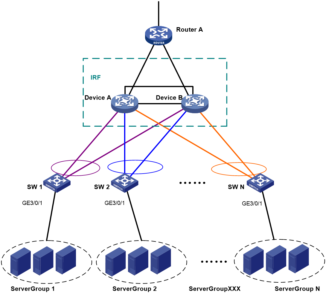
Figure 6 Network diagram during expansion (Device C and Device D are added to the IRF fabric)

Figure 7 Network diagram after expansion (Four-chassis IRF fabric with BFD MAD enabled)

|
|
NOTE: For more information about the VLAN and IP address assignment plan, and the interconnect port plan, see "Example: Setting up a LACP MAD-enabled four-chassis IRF fabric." |
Restrictions and guidelines
· To avoid single points of failure, use multichassis link aggregations to connect the IRF fabric to the downstream and upstream devices.
· To prevent IRF split from affecting services, configure BFD MAD for the IRF fabric. This MAD method provides fast detection speed and configuration flexibility. It does not have any requirements on intermediate devices. However, this method requires additional Layer 3 interfaces.
· BFD MAD is mutually exclusive with STP. Make sure STP is disabled on the interfaces used for BFD MAD.
Applicable hardware and software versions
The following matrix shows the hardware and software versions to which this configuration example is applicable:
|
Hardware |
Software version |
|
S12500G-AF switch series |
Release 7639P01 and later |
|
S10500X switch series |
Release 7639P01 and later |
|
S10500 switch series |
Release 7639P01 and later |
|
S7500E-X switch series |
Release 7639P01 and later |
|
S7500E switch series |
Release 7639P01 and later |
|
S7500X switch series |
Release 7639P01 and later |
Procedures
Setting up the IRF fabric (by adding Device C and Device D to the IRF fabric)
Device A and Device B have formed an IRF fabric. You can expand the IRF fabric by adding Device C and Device D to the IRF fabric.
Configuring the IRF fabric
# Bind Ten-GigabitEthernet 1/0/1 to IRF-port 1/1.
<DeviceA> system-view
[DeviceA] interface ten-gigabitethernet 1/0/1
[DeviceA-Ten-GigabitEthernet1/0/1] shutdown
[DeviceA-Ten-GigabitEthernet1/0/1] quit
[DeviceA] irf-port 1/1
[DeviceA-irf-port1/1] port group interface ten-gigabitethernet 1/0/1
[DeviceA-irf-port1/1] quit
[DeviceA] interface ten-gigabitethernet 1/0/1
[DeviceA-Ten-GigabitEthernet1/0/1] undo shutdown
[DeviceA-Ten-GigabitEthernet1/0/1] quit
# Bind Ten-GigabitEthernet 1/0/2 to IRF-port 2/2.
[DeviceA] interface ten-gigabitEthernet 1/0/2
[DeviceA-Ten-GigabitEthernet1/0/2] undo shutdown
[DeviceA-Ten-GigabitEthernet1/0/2] quit
[DeviceA] irf-port 2/2
[DeviceA-irf-port2/2] port group interface ten-gigabitethernet1/0/2
[DeviceA-irf-port2/2] quit
[DeviceA] interface ten-gigabitEthernet 1/0/2
[DeviceA-Ten-GigabitEthernet1/0/2] undo shutdown
[DeviceA-Ten-GigabitEthernet1/0/2] quit
# Save the running configuration.
[DeviceA] save
The current configuration will be written to the device. Are you sure? [Y/N]:y
Please input the file name(*.cfg)[cfa0:/irf.cfg]
(To leave the existing filename unchanged, press the enter key):
cfa0:/irf.cfg exists, overwrite? [Y/N]:y
Validating file. Please wait.....................................
Saved the current configuration to mainboard device successfully.
[DeviceA] irf-port-configuration active
Configuring Device C
# Assign member ID 3 to Device C.
<DeviceC> system-view
[DeviceC] irf member 3
# Bind Ten-GigabitEthernet 3/0/1 to IRF-port 1.
[DeviceC] irf-port 1
[DeviceC-irf-port1] port group interface ten-gigabitethernet 3/0/1
[DeviceC-irf-port1] quit
# Bind Ten-GigabitEthernet 3/0/2 to IRF-port 2.
[DeviceC] irf-port 2
[DeviceC-irf-port2] port group interface ten-gigabitethernet3/0/2
[DeviceC-irf-port2] quit
# Save the configuration.
[DeviceC] save
The current configuration will be written to the device. Are you sure? [Y/N]:y
Please input the file name(*.cfg)[cfa0:/irf.cfg]
(To leave the existing filename unchanged, press the enter key):
cfa0:/irf.cfg exists, overwrite? [Y/N]:y
Validating file. Please wait.....................................
Saved the current configuration to mainboard device successfully.
# Connect IRF ports on Device B and Device C, as shown in Figure 7.
# Enable IRF mode.
[DeviceC] chassis convert mode irf
The device will switch to IRF mode and reboot. Continue? [Y/N]:y
You are recommended to save the current running configuration and specify the c
onfiguration file for the next startup. Continue? [Y/N]:y
Do you want to convert the content of the next startup configuration file flash
:/startup.cfg to make it available in stack mode? [Y/N]:y
Now rebooting, please wait...
Configuring Device D
# Assign member ID 4 to Device D.
<DeviceD> system-view
[DeviceD] irf member 4
# Bind Ten-GigabitEthernet 4/0/1 to IRF-port 1.
[DeviceD] irf-port 1
[DeviceD-irf-port1] port group interface ten-gigabitethernet 4/0/1
[DeviceD-irf-port1] quit
# Bind Ten-GigabitEthernet 4/0/2 to IRF-port 2.
[DeviceD] irf-port 2
[DeviceD-irf-port2] port group interface ten-gigabitethernet4/0/2
[DeviceD-irf-port2] quit
# Save the configuration.
[DeviceD] save
The current configuration will be written to the device. Are you sure? [Y/N]:y
Please input the file name(*.cfg)[cfa0:/irf.cfg]
(To leave the existing filename unchanged, press the enter key):
cfa0:/irf.cfg exists, overwrite? [Y/N]:y
Validating file. Please wait.....................................
Saved the current configuration to mainboard device successfully.
# Connect IRF ports on Device C and Device D, and connect IRF ports on Device A and Device D as shown in Figure 7.
# Enable IRF mode.
[DeviceD] chassis convert mode irf
The device will switch to IRF mode and reboot. Continue? [Y/N]:y
You are recommended to save the current running configuration and specify the c
onfiguration file for the next startup. Continue? [Y/N]:y
Do you want to convert the content of the next startup configuration file flash
:/startup.cfg to make it available in stack mode? [Y/N]:y
Now rebooting, please wait...
Setting up the IRF fabric (by merging the old IRF fabric and IRF-C)
Configuring the IRF fabric
# Bind Ten-GigabitEthernet 1/0/1 to IRF-port 1/1.
<DeviceA> system-view
[DeviceA] interface ten-gigabitethernet 1/0/1
[DeviceA-Ten-GigabitEthernet1/0/1] shutdown
[DeviceA-Ten-GigabitEthernet1/0/1] quit
[DeviceA] irf-port 1/1
[DeviceA-irf-port1/1] port group interface ten-gigabitethernet 1/0/1
[DeviceA-irf-port1/1] quit
[DeviceA] interface ten-gigabitethernet 1/0/1
[DeviceA-Ten-GigabitEthernet1/0/1] undo shutdown
[DeviceA-Ten-GigabitEthernet1/0/1] quit
# Bind Ten-GigabitEthernet 1/0/2 to IRF-port 2/2.
[DeviceA] interface ten-gigabitethernet 1/0/2
[DeviceA-Ten-GigabitEthernet1/0/2] shutdown
[DeviceA-Ten-GigabitEthernet1/0/2] quit
[DeviceA] irf-port 2/2
[DeviceA-irf-port2/2] port group interface ten-gigabitethernet1/0/2
[DeviceA-irf-port2/2] quit
[DeviceA] interface ten-gigabitethernet 1/0/2
[DeviceA-Ten-GigabitEthernet1/0/2] undo shutdown
[DeviceA-Ten-GigabitEthernet1/0/2] quit
# Save the running configuration.
[DeviceA] save
The current configuration will be written to the device. Are you sure? [Y/N]:y
Please input the file name(*.cfg)[cfa0:/irf.cfg]
(To leave the existing filename unchanged, press the enter key):
cfa0:/irf.cfg exists, overwrite? [Y/N]:y
Validating file. Please wait.....................................
Saved the current configuration to mainboard device successfully.
[DeviceA] irf-port-configuration active
Configuring IRF-C
# Set the member IDs of IRF-C.
<DeviceC> system-view
[DeviceC] irf member 1 renumber 3
Renumbering the member ID may result in configuration change or loss. Continue?[
Y/N]y
[DeviceC] irf member 2 renumber 4
Renumbering the member ID may result in configuration change or loss. Continue?[
Y/N]y
# Save the running configuration and restart the devices to have the new member IDs take effect.
[DeviceC] quit
<DeviceC> reboot
Start to check configuration with next startup configuration file, please wait..
.......DONE!
Current configuration may be lost after the reboot, save current configuration?
[Y/N]:y
Please input the file name(*.cfg)[cfa0:/irf.cfg]
(To leave the existing filename unchanged, press the enter key):
This command will reboot the device. Continue? [Y/N]:y
# Bind Ten-GigabitEthernet 3/3/0/1 to IRF-port 3/1.
<DeviceC> system-view
[DeviceC] interface ten-gigabitethernet 3/3/0/1
[DeviceC-Ten-GigabitEthernet3/3/0/1] shutdown
[DeviceC-Ten-GigabitEthernet3/3/0/1] quit
[DeviceC] irf-port 3/1
[DeviceC-irf-port3/1] port group interface ten-gigabitethernet 3/3/0/1
[DeviceC-irf-port3/1] quit
[DeviceC] interface ten-gigabitethernet 3/3/0/1
[DeviceC-Ten-GigabitEthernet3/3/0/1] undo shutdown
[DeviceC-Ten-GigabitEthernet3/3/0/1] quit
# Bind Ten-GigabitEthernet 3/3/0/2 to IRF-port 4/2.
[DeviceC] interface ten-gigabitethernet 3/3/0/2
[DeviceC-Ten-GigabitEthernet3/3/0/2] shutdown
[DeviceC-Ten-GigabitEthernet3/3/0/2] quit
[DeviceC] irf-port 4/2
[DeviceC-irf-port4/2] port group interface ten-gigabitethernet3/3/0/2
[DeviceC-irf-port4/2] quit
[DeviceC] interface ten-gigabitethernet 3/3/0/2
[DeviceC-Ten-GigabitEthernet3/3/0/2] undo shutdown
[DeviceC-Ten-GigabitEthernet3/3/0/2] quit
# Save the running configuration.
[DeviceC] save
The current configuration will be written to the device. Are you sure? [Y/N]:y
Please input the file name(*.cfg)[cfa0:/irf.cfg]
(To leave the existing filename unchanged, press the enter key):
cfa0:/irf.cfg exists, overwrite? [Y/N]:y
Validating file. Please wait.....................................
Saved the current configuration to mainboard device successfully.
[DeviceC] irf-port-configuration active
# Connect IRF ports on Device B and Device C, and connect IRF ports on Device A and Device D as shown in Figure 7.
Configuring BFD MAD settings
After the new IRF fabric is formed, the master's system name becomes the fabric's system name. You can configure software features on the fabric as you do on a standalone device. This example configures Device A.
|
|
IMPORTANT: To have BFD MAD operate correctly, make sure the VLAN used for BFD MAD is not configured with other services. |
# Create VLAN-interface 13 for use by BFD MAD.
<DeviceA> system-view
[DeviceA] vlan 13
[DeviceA-vlan13] quit
[DeviceA] interface vlan-interface 13
[DeviceA-Vlan-interface13] mad bfd enable
[DeviceA-Vlan-interface13] mad ip address 172.1.1.1 24 member 1
[DeviceA-Vlan-interface13] mad ip address 172.1.1.2 24 member 2
[DeviceA-Vlan-interface13] mad ip address 172.1.1.3 24 member 3
[DeviceA-Vlan-interface13] mad ip address 172.1.1.4 24 member 4
[DeviceA-Vlan-interface13] undo shutdown
[DeviceA-Vlan-interface13] quit
# Assign the Layer 2 Ethernet port connected to the Layer 2 switch to VLAN 13, and disable STP on that port.
[DeviceA] interface range ten-gigabitEthernet 1/3/0/1 ten-gigabitEthernet 2/3/0/1 ten-gigabitEthernet 3/3/0/1 ten-gigabitEthernet 4/3/0/1
[DeviceA-if-range] undo stp enable
[DeviceA-if-range] port access vlan 13
[DeviceA-if-range] quit
Configuring IRF downlink services
In this example, for better illustration, all service settings configured before the expansion are cleared. In live networks, if some of the following service settings already exist in the IRF fabric before expansion, you do not need to configure them after expansion, for example, port IP addresses.
Configuring the IRF fabric
# Create aggregate interface Bridge-Aggregation 1.
[DeviceA] interface bridge-aggregation 1
[DeviceA-Bridge-Aggregation1] quit
# Assign the downlink ports connected to SW 1 to aggregation group 1.
[DeviceA] interface range ten-gigabitEthernet 1/3/0/3 ten-gigabitEthernet 2/3/0/3 ten-gigabitEthernet 3/3/0/3 ten-gigabitEthernet 4/3/0/3
[DeviceA-if-range] port link-aggregation group 1
[DeviceA-if-range] quit
# Create aggregate interface Bridge-Aggregation 2.
[DeviceA] interface bridge-aggregation 2
[DeviceA-Bridge-Aggregation2] quit
# Assign the downlink ports connected to SW 2 to aggregation group 2.
[DeviceA] interface range ten-gigabitEthernet 1/3/0/4 ten-gigabitEthernet 2/3/0/4 ten-gigabitEthernet 3/3/0/4 ten-gigabitEthernet 4/3/0/4
[DeviceA-if-range] port link-aggregation group 2
[DeviceA-if-range] quit
# Connect Device A to SW 1 through VLAN-interface 10.
[DeviceA] vlan 10
[DeviceA-vlan10] quit
[DeviceA] interface vlan-interface 10
[DeviceA-Vlan-interface10] ip address 172.24.10.254 24
[DeviceA-Vlan-interface10] quit
[DeviceA] interface bridge-aggregation 1
[DeviceA-Bridge-Aggregation1] port link-type trunk
[DeviceA-Bridge-Aggregation1] undo port trunk permit vlan 1
[DeviceA-Bridge-Aggregation1] port trunk permit vlan 10
[DeviceA-Bridge-Aggregation1] quit
# Connect Device A to SW 2 through VLAN-interface 20.
[DeviceA] vlan 20
[DeviceA-vlan20] quit
[DeviceA] interface vlan-interface 20
[DeviceA-Vlan-interface20] ip address 172.24.20.254 24
[DeviceA-Vlan-interface20] quit
[DeviceA] interface bridge-aggregation 2
[DeviceA-Bridge-Aggregation2] port link-type trunk
[DeviceA-Bridge-Aggregation2] undo port trunk permit vlan 1
[DeviceA-Bridge-Aggregation2] port trunk permit vlan 20
[DeviceA-Bridge-Aggregation2] quit
Configuring SW 1
# Create aggregate interface Bridge-Aggregation 1.
<SW1> system-view
[SW1] interface bridge-aggregation 1
[SW1-Bridge-Aggregation1] quit
# Assign the uplink ports connected to the IRF fabric to the aggregation group.
[SW1] interface range ten-gigabitethernet 2/0/21 to ten-gigabitethernet 2/0/24
[SW1-if-range] port link-aggregation group 1
[SW1-if-range] quit
# Create all VLANs.
[SW1] vlan all
# Configure IRF fabric-facing interface Bridge-Aggregation 1.
[SW1] interface bridge-aggregation 1
[SW1-Bridge-Aggregation1] port link-type trunk
[SW1-Bridge-Aggregation1] undo port trunk permit vlan 1
[SW1-Bridge-Aggregation1] port trunk permit vlan 10
[SW1-Bridge-Aggregation1] quit
# Configure server-facing interface GigabitEthernet 3/0/1.
[SW1] interface gigabitethernet 3/0/1
[SW1-GigabitEthernet3/0/1] port link-type trunk
[SW1-GigabitEthernet3/0/1] port trunk permit vlan all
[SW1-GigabitEthernet3/0/1] undo port trunk permit vlan 1
[SW1-GigabitEthernet3/0/1] quit
Configuring SW 2
# Create aggregate interface Bridge-Aggregation 1.
<SW2> system-view
[SW2] interface bridge-aggregation 1
[SW2-Bridge-Aggregation1] quit
# Assign the uplink ports connected to the IRF fabric to the aggregation group.
[SW2] interface range ten-gigabitethernet 2/0/21 to ten-gigabitethernet 2/0/24
[SW2-if-range] port link-aggregation group 1
[SW2-if-range] quit
# Create all VLANs.
[SW2] vlan all
# Configure IRF fabric-facing interface Bridge-Aggregation 1.
[SW2] interface bridge-aggregation 1
[SW2-Bridge-Aggregation1] port link-type trunk
[SW2-Bridge-Aggregation1] undo port trunk permit vlan 1
[SW2-Bridge-Aggregation1] port trunk permit vlan 20
[SW2-Bridge-Aggregation1] quit
# Configure server-facing interface GigabitEthernet 3/0/1.
[SW2] interface gigabitethernet 3/0/1
[SW2-GigabitEthernet3/0/1] port link-type trunk
[SW2-GigabitEthernet3/0/1] port trunk permit vlan all
[SW2-GigabitEthernet3/0/1] undo port trunk permit vlan 1
[SW2-GigabitEthernet3/0/1] quit
Configuring IRF uplink services
Configuring the IRF fabric
# Create aggregate interface Bridge-Aggregation 1024.
[DeviceA] interface bridge-aggregation 1024
[DeviceA-Bridge-Aggregation1024] quit
# Assign the uplink ports connected to egress router Router A to the aggregation group.
[DeviceA] interface range ten-gigabitethernet 1/3/0/8 ten-gigabitethernet 2/3/0/8 ten-gigabitethernet 3/3/0/8 ten-gigabitethernet 4/3/0/8
[DeviceA-if-range] port link-aggregation group 1024
[DeviceA-if-range] quit
# Connect Device A to Router A through VLAN-interface 41.
[DeviceA] vlan 41
[DeviceA-vlan41] quit
[DeviceA] interface vlan-interface 41
[DeviceA-Vlan-interface41] ip address 172.24.41.254 24
[DeviceA-Vlan-interface41] quit
[DeviceA] interface bridge-aggregation 1024
[DeviceA-Bridge-Aggregation1024] port access vlan 41
[DeviceA-Bridge-Aggregation1024] quit
# Configure OSPF between the IRF fabric and Router A.
[DeviceA] interface loopback 0
[DeviceA-LoopBack0] ip address 172.24.254.1 255.255.255.255
[DeviceA-LoopBack0] quit
[DeviceA] ospf 1 router-id 172.24.254.1
[DeviceA-ospf-1] import-route direct
[DeviceA-ospf-1] area 0
[DeviceA-ospf-1-area-0.0.0.0] network 172.24.41.0 0.0.0.255
[DeviceA-ospf-1-area-0.0.0.0] quit
[DeviceA-ospf-1] quit
Configuring Router A
|
|
NOTE: In this example, the egress router configuration only includes the connection to the IRF fabric. |
# Create aggregate interface Bridge-Aggregation 1. Assign the downlink ports connected to the IRF fabric to Bridge-Aggregation 1.
<RouterA> system-view
[RouterA] interface bridge-aggregation 1
[RouterA-Bridge-Aggregation1] quit
[RouterA] interface range ten-gigabitethernet 2/0/1 to interface ten-gigabitethernet 2/0/4
[RouterA-if-range] port link-aggregation group 1
[RouterA-if-range] quit
# Connect Router A to the IRF fabric through VLAN-interface 41.
[RouterA] vlan 41
[RouterA-vlan41] quit
[RouterA] interface vlan-interface 41
[RouterA-Vlan-interface41] ip address 172.24.41.2 24
[RouterA-Vlan-interface41] quit
[RouterA] interface bridge-aggregation 1
[RouterA-Bridge-Aggregation1] port access vlan 41
[RouterA-Bridge-Aggregation1] quit
# Connect Router A to the external network through VLAN-interface 50.
[RouterA] vlan 50
[RouterA-vlan50] quit
[RouterA] interface vlan-interface 50
[RouterA-Vlan-interface50] ip address 172.24.1.2 24
[RouterA-Vlan-interface50] quit
[RouterA] interface ten-gigabitethernet 4/0/3
[RouterA-Ten-GigabitEthernet4/0/3] port link-mode bridge
[RouterA-Ten-GigabitEthernet4/0/3] port access vlan 50
[RouterA-Ten-GigabitEthernet4/0/3] quit
# Configure OSPF between the IRF fabric and Router A.
[RouterA] interface loopback 0
[RouterA-LoopBack0] ip addresss 172.24.254.2 255.255.255.255
[RouterA-LoopBack0] quit
[RouterA] ospf 1 router-id 172.24.254.2
[RouterA-ospf-1] import-route direct
[RouterA-ospf-1] area 0
[RouterA-ospf-1-area-0.0.0.0] network 172.24.41.0 0.0.0.255
[RouterA-ospf-1-area-0.0.0.0] quit
[RouterA-ospf-1] quit
Verifying the configuration
Verify that the IRF fabric and multichassis link aggregation configuration operate correctly.
Verifying the IRF function
# Execute the display irf topology command in any view. Verify that all IRF ports are up.
<DeviceA> display irf topology
Topology Info
-------------------------------------------------------------------------
IRF-Port1 IRF-Port2
Switch Link neighbor Link neighbor Belong To
1 UP 4 UP 2 0210-fc01-0000
4 UP 3 UP 1 0210-fc01-0000
3 UP 2 UP 4 0210-fc01-0000
2 UP 1 UP 3 0210-fc01-0000
The command output shows that the member chassis have formed an IRF fabric.
Verifying the link backup function of multichassis aggregations
# Shut down Ten-GigabitEthernet 1/3/0/8, an uplink port of the IRF fabric.
[DeviceA] interface ten-gigabitethernet 1/3/0/8
[DeviceA-Ten-GigabitEthernet1/3/0/8] shutdown
# Ping an IP address on the public network from a PC in Server Group 1.
The output shows that the address can be pinged after transient traffic disruption.
# Bring up Ten-GigabitEthernet 1/3/0/8 and shut down Ten-GigabitEthernet 2/3/0/8, another uplink port of the IRF fabric.
[DeviceA-Ten-GigabitEthernet1/3/0/8] undo shutdown
[DeviceA-Ten-GigabitEthernet1/3/0/8] quit
[DeviceA] interface ten-gigabitethernet 2/3/0/8
[DeviceA-Ten-GigabitEthernet2/3/0/8] shutdown
# Ping the IP address on the public network from the PC.
The output shows that the address can be pinged after transient traffic disruption.
Configuration files
IRF fabric
#
irf mac-address persistent always
irf auto-update enable
undo irf auto-merge enable
undo irf link-delay
irf member 1 priority 1
irf member 2 priority 1
irf member 3 priority 1
irf member 4 priority 1
#
ospf 1 router-id 172.24.254.1
import-route direct
area 0.0.0.0
network 172.24.41.0 0.0.0.255
#
vlan 10
#
vlan 20
#
vlan 13
#
vlan 41
#
irf-port 1/1
port group interface Ten-GigabitEthernet1/2/0/4 mode enhanced
#
irf-port 1/2
port group interface Ten-GigabitEthernet1/2/0/1 mode enhanced
#
irf-port 2/1
port group interface Ten-GigabitEthernet2/4/0/2 mode enhanced
#
irf-port 2/2
port group interface Ten-GigabitEthernet2/3/0/30 mode enhanced
#
irf-port 3/1
port group interface Ten-GigabitEthernet3/3/0/15 mode enhanced
#
irf-port 3/2
port group interface Ten-GigabitEthernet3/2/0/1 mode enhanced
#
irf-port 4/1
port group interface Ten-GigabitEthernet4/6/0/4 mode enhanced
#
irf-port 4/2
port group interface Ten-GigabitEthernet4/6/0/2 mode enhanced
#
interface bridge-aggregation 1
port link-type trunk
undo port trunk permit vlan 1
port trunk permit vlan 10
mad enable
link-aggregation mode dynamic
#
interface bridge-aggregation 2
port link-type trunk
undo port trunk permit vlan 1
port trunk permit vlan 20
#
interface bridge-aggregation 1024
port access vlan 41
#
interface loopback 0
ip address 172.24.254.1 255.255.255.255
#
interface vlan-interface 10
ip address 172.24.10.254 24
#
interface vlan-interface13
mad bfd enable
mad ip address 1.1.1.4 255.255.255.0 member 1
mad ip address 1.1.1.1 255.255.255.0 member 2
mad ip address 1.1.1.2 255.255.255.0 member 3
mad ip address 1.1.1.3 255.255.255.0 member 4
#
interface vlan-interface 20
ip address 172.24.20.254 24
#
interface vlan-interface 41
ip address 172.24.41.254 24
#
interface Ten-GigabitEthernet 1/3/0/1
port link-mode bridge
port access vlan 13
undo stp enable
#
interface Ten-GigabitEthernet 1/3/0/3
port link-mode bridge
port link-type trunk
undo port trunk permit vlan 1
port trunk permit vlan 10
port link-aggregation group 1
#
interface Ten-GigabitEthernet 1/3/0/4
port link-mode bridge
port link-type trunk
undo port trunk permit vlan 1
port trunk permit vlan 20
port link-aggregation group 2
#
interface Ten-GigabitEthernet 1/3/0/8
port link-mode bridge
port access vlan 41
port link-aggregation group 1024
#
interface Ten-GigabitEthernet 2/3/0/1
port link-mode bridge
port access vlan 13
undo stp enable
#
interface Ten-GigabitEthernet 2/3/0/3
port link-mode bridge
port link-type trunk
undo port trunk permit vlan 1
port trunk permit vlan 10
port link-aggregation group 1
#
interface Ten-GigabitEthernet 2/3/0/4
port link-mode bridge
port link-type trunk
undo port trunk permit vlan 1
port trunk permit vlan 20
port link-aggregation group 2
#
interface Ten-GigabitEthernet 2/3/0/8
port link-mode bridge
port access vlan 41
port link-aggregation group 1024
#
interface Ten-GigabitEthernet 3/3/0/1
port link-mode bridge
port access vlan 13
undo stp enable
#
interface Ten-GigabitEthernet 3/3/0/3
port link-mode bridge
port link-type trunk
undo port trunk permit vlan 1
port trunk permit vlan 10
port link-aggregation group 1
#
interface Ten-GigabitEthernet 3/3/0/4
port link-mode bridge
port link-type trunk
undo port trunk permit vlan 1
port trunk permit vlan 20
port link-aggregation group 2
#
interface Ten-GigabitEthernet 3/3/0/8
port link-mode bridge
port access vlan 41
port link-aggregation group 1024
#
interface Ten-GigabitEthernet 4/3/0/1
port link-mode bridge
port access vlan 13
undo stp enable
#
interface Ten-GigabitEthernet 4/3/0/3
port link-mode bridge
port link-type trunk
undo port trunk permit vlan 1
port trunk permit vlan 10
port link-aggregation group 1
#
interface Ten-GigabitEthernet 4/3/0/4
port link-mode bridge
port link-type trunk
undo port trunk permit vlan 1
port trunk permit vlan 20
port link-aggregation group 2
#
interface Ten-GigabitEthernet 4/3/0/8
port link-mode bridge
port access vlan 41
port link-aggregation group 1024
#
SW 1
#
vlan 10
#
interface bridge-aggregation 1
port link-type trunk
undo port trunk permit vlan 1
port trunk permit vlan 10
link-aggregation mode dynamic
#
interface gigabitethernet 3/0/1
port link-mode bridge
port link-type trunk
undo port trunk permit vlan 1
port trunk permit vlan 2 to 4094
#
interface Ten-GigabitEthernet 2/0/21
port link-mode bridge
port link-type trunk
undo port trunk permit vlan 1
port trunk permit vlan 10
port link-aggregation group 1
#
interface Ten-GigabitEthernet 2/0/22
port link-mode bridge
port link-type trunk
undo port trunk permit vlan 1
port trunk permit vlan 10
port link-aggregation group 1
#
interface Ten-GigabitEthernet 2/0/23
port link-mode bridge
port link-type trunk
undo port trunk permit vlan 1
port trunk permit vlan 10
port link-aggregation group 1
#
interface Ten-GigabitEthernet 2/0/24
port link-mode bridge
port link-type trunk
undo port trunk permit vlan 1
port trunk permit vlan 10
port link-aggregation group 1
#
SW 2
#
vlan 20
#
interface bridge-aggregation 1
port link-type trunk
undo port trunk permit vlan 1
port trunk permit vlan 20
#
interface gigabitethernet 3/0/1
port link-mode bridge
port link-type trunk
undo port trunk permit vlan 1
port trunk permit vlan 2 to 4094
#
interface Ten-GigabitEthernet 2/0/21
port link-mode bridge
port link-type trunk
undo port trunk permit vlan 1
port trunk permit vlan 20
port link-aggregation group 1
#
interface Ten-GigabitEthernet 2/0/22
port link-mode bridge
port link-type trunk
undo port trunk permit vlan 1
port trunk permit vlan 20
port link-aggregation group 1
#
interface Ten-GigabitEthernet 2/0/23
port link-mode bridge
port link-type trunk
undo port trunk permit vlan 1
port trunk permit vlan 20
port link-aggregation group 1
#
interface Ten-GigabitEthernet 2/0/24
port link-mode bridge
port link-type trunk
undo port trunk permit vlan 1
port trunk permit vlan 20
port link-aggregation group 1
#
interface Ten-GigabitEthernet 2/0/41
port link-mode bridge
port access vlan 13
#
interface Ten-GigabitEthernet 2/0/42
port link-mode bridge
port access vlan 13
#
interface Ten-GigabitEthernet 2/0/43
port link-mode bridge
port access vlan 13
#
interface Ten-GigabitEthernet 2/0/44
port link-mode bridge
port access vlan 13
#
Router A
#
ospf 1 router-id 172.24.254.2
import-route direct
area 0.0.0.0
network 172.24.41.0 0.0.0.255
#
vlan 41
#
vlan 50
#
interface bridge-aggregation 1
port access vlan 41
#
interface loopback 0
ip address 172.24.254.2 255.255.255.255
#
interface vlan-interface 41
ip address 172.24.41.2 24
#
interface vlan-interface 50
ip address 172.24.1.2 24
#
interface Ten-GigabitEthernet 2/0/1
port link-mode bridge
port access vlan 41
port link-aggregation group 1
#
interface Ten-GigabitEthernet 2/0/2
port link-mode bridge
port access vlan 41
port link-aggregation group 1
#
interface Ten-GigabitEthernet 2/0/3
port link-mode bridge
port access vlan 41
port link-aggregation group 1
#
interface Ten-GigabitEthernet 2/0/4
port link-mode bridge
port access vlan 41
port link-aggregation group 1
#
interface Ten-GigabitEthernet 2/0/12
port link-mode bridge
port access vlan 50
#