- Table of Contents
- Related Documents
-
| Title | Size | Download |
|---|---|---|
| 03-IRF Member Replacement Configuration Examples (Modular Devices) | 130.92 KB |
Contents
Example: Replacing an IRF-connect interface module with a new interface module
Applicable scenario: single IRF-connect interface module per chassis
Applicable hardware and software versions
Introduction
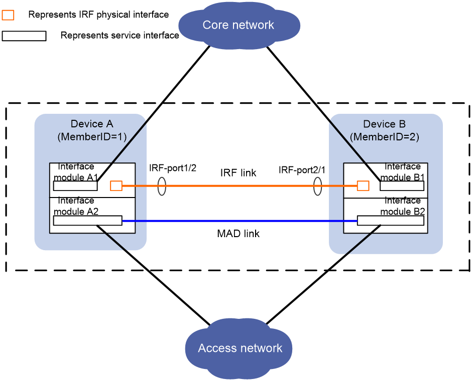
This document provides examples for replacing the only interface module that has IRF physical interfaces on an IRF member device with a new interface module.
|
|
NOTE: The interface module that has IRF physical interfaces is also called an IRF-connect interface module in this document. |
Because the only IRF-connect interface module fails and no interface modules can provide IRF physical interfaces, you need to replace the interface module with a new interface module. During interface module replacement, the IRF fabric splits.
Prerequisites
The configuration examples in this document were created and verified in a lab environment, and all the devices were started with the factory default configuration. When you are working on a live network, make sure you understand the potential impact of every command on your network.
This document assumes that you have basic knowledge of IRF.
Example: Replacing an IRF-connect interface module with a new interface module
Applicable scenario: single IRF-connect interface module per chassis
This example applies when you use only one interface module in each IRF member chassis to establish IRF links.
As shown in Figure 1, the IRF-connect interface module on an IRF member device fails when the IRF fabric is integrated, and no interface modules can provide IRF physical interfaces. You need to replace the IRF-connect interface module with a new interface module. In this case, IRF split inevitably occurs. To reduce the impact of IRF split on network services, follow the configuration procedures and configuration restrictions and guidelines in this example to replace the IRF-connect interface module.
If the IRF member device is installed with a high-speed interface module (for example, 40 Gbps) and a low-speed interface module (for example, 10 Gbps), deploy IRF links on the high-speed interface module as a best practice. To avoid IRF split when you replace the high-speed interface module with a new interface module, you can temporarily configure interfaces on the low-speed interface module as IRF physical interfaces. In this situation, interfaces on both the high-speed and low-speed interface modules are used as IRF physical interfaces. After you successfully replace the high-speed interface module and the IRF connections recover, remove the interfaces on the low-speed interface module from the IRF port.
|
|
NOTE: This document does not cover the contents for replacing an IRF-connect interface module on a device installed with both high-speed and low-speed interface modules. |
Network configuration
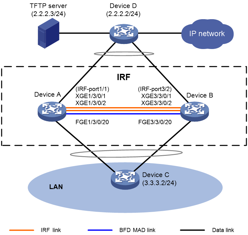
As shown in Figure 2, Device A and Device B are S12508X-AF switches. They have set up an IRF fabric. Device A is the master device and its member ID is 1, and Device B is the standby device and its member ID is 3. BFD MAD is used for multi-active collision detection.
The only IRF-connect interface module in slot 3 on Device A fails when the IRF fabric is integrated. No IRF links can be added on other interface modules. You need to replace the IRF-connect interface module with a new IRF-connect interface module.
Applicable hardware and software versions
The following matrix shows the hardware and software versions to which this configuration example is applicable:
|
Hardware |
Software version |
|
S12500G-AF switch series |
Release 7639P01 and later |
|
S10500X switch series |
Release 7639P01 and later |
|
S10500 switch series |
Release 7639P01 and later |
|
S7500E-X switch series |
Release 7639P01 and later |
|
S7500E switch series |
Release 7639P01 and later |
|
S7500X switch series |
Release 7639P01 and later |
Restrictions and guidelines
Before IRF-connect interface module replacement
· Make sure all member devices and cards except the replaced interface module are in stable state. For this purpose, execute the display system stable state command and verify that the value for the State field is Stable. If a member device or card is not in stable state, identify the reason. Do not perform the replacement operation unless all member devices and cards except the replaced interface module are in stable state.
· Prepare scripts in advance for shutting down and bringing up uplink and downlink service interfaces on Device A. To prevent omission of service interfaces from resulting in exceptions in the replacement process, make sure the scripts contain all service interfaces on the device.
· Verify availability of session logging in the login software and make sure it is enabled.
Operation log helps quick analysis and identification of issues that result in a failed replacement. Login software, for example, HyperTerminal and PuTTY, typically provides session recording to log all user operations and save the operations to a .txt file for later retrieval.
If the login software does not support session recording, manually record all operations throughput the replacement procedure.
During IRF-connect interface module replacement
· To avoid configuration loss, do not save the running configuration on any IRF member device when the IRF fabric splits.
· After the master device starts up after interface module replacement, make sure all member devices and cards are running correctly. Use the display interface brief command to verify that all interfaces are displayed, and then wait for 2 minutes before you move to the next step.
After IRF-connect interface module replacement
· Make sure all member devices and cards are in stable state. For this purpose, execute the display system stable state command and verify that the value for the State field is Stable.
· Verify that all services on the IRF fabric are running correctly. If a service cannot run correctly, locate and resolve the issue as soon as possible.
Prerequisites
1. Configure NSR settings on the IRF fabric:
During the replacement, process-level active/standby switchover might occur for routing protocols, for example, BGP and OSPF. This issue causes routing neighbor flapping and affects packet forwarding. For high availability, configure nonstop routing (NSR) for routing protocols. Before replacing Device B, configure NSR settings and save the configuration. In this example, OSPF NSR and BGP NSR are configured for illustration.
# Enable NSR for OSPF process 100.
<IRF> system-view
[IRF] ospf 100
[IRF-ospf-100] non-stop-routing
[IRF-ospf-100] display ospf non-stop-routing status
OSPF Process 100 with Router ID 1.1.1.1
Non Stop Routing information
Non Stop Routing capability : Enabled
Upgrade phase : Normal
[IRF-ospf-100] quit
[IRF] quit
# Enable NSR for BGP process 100.
[IRF] bgp 100
[IRF-bgp-default] non-stop-routing
[IRF-bgp-default] display bgp non-stop-routing status
BGP NSR status: Ready
Location of preferred standby process: Chassis 1 Slot 0
TCP NSR status: Ready
[IRF-bgp-default] quit
[IRF-bgp] quit
[IRF] quit
2. Examine whether single-armed service links exist.
IRF split occurs during the replacement process. In addition, you need to shut down all service interfaces on Device A. For high availability, deploy physical links dual-homed to both member devices for each uplink device and downlink device. That is, connect Device D to both Device A and Device B, and connect Device C to both Device A and Device B. If single-armed services exist, service access exception will occur during the replacement process. As a best practice, add backup links for single-armed services.
3. Check IRF status and collect information:
Before the replacement, you must check the device status, HA status, IRF status, and MAD status.
|
|
IMPORTANT: Make sure all cards except the interface module to be replaced are in stable state. If a card is not in stable state, identify the reason. Do not replace the interface module with a new interface module unless other cards are all in stable state. |
# Display device information.
<IRF> display device
Slot Type State Subslot Soft Ver Patch Ver
1/0 LSXM1SUPB1 Master 0 S12508X-AF-2713 None
1/1 NONE Absent 0 NONE None
1/2 NONE Absent 0 NONE None
1/3 LSXM1CGQ18QGHB1 Fault 0 S12508X-AF-2713 None
1/4 NONE Absent 0 NONE None
1/5 NONE Absent 0 NONE None
1/6 NONE Absent 0 NONE None
1/7 NONE Absent 0 NONE None
1/8 NONE Absent 0 NONE None
1/9 NONE Absent 0 NONE None
1/10 NONE Absent 0 NONE None
1/11 NONE Absent 0 NONE None
1/12 NONE Absent 0 NONE None
1/13 NONE Absent 0 NONE None
1/14 NONE Absent 0 NONE None
1/15 NONE Absent 0 NONE None
3/0 LSXM1SUPB1 Standby 0 S12508X-AF-2713 None
3/1 NONE Absent 0 NONE None
3/2 NONE Absent 0 NONE None
3/3 LSXM1CGQ18QGHB1 Normal 0 S12508X-AF-2713 None
3/4 NONE Absent 0 NONE None
3/5 NONE Absent 0 NONE None
3/6 NONE Absent 0 NONE None
3/7 NONE Absent 0 NONE None
3/8 NONE Absent 0 NONE None
3/9 NONE Absent 0 NONE None
3/10 NONE Absent 0 NONE None
3/11 NONE Absent 0 NONE None
3/12 NONE Absent 0 NONE None
3/13 NONE Absent 0 NONE None
3/14 NONE Absent 0 NONE None
3/15 NONE Absent 0 NONE None
# Display system stable status.
<IRF> display system stable state
System state : Stable
Redundancy state : Stable
Chassis Slot CPU Role State
1 0 0 Active Stable
* 1 3 0 Other Stable
3 0 0 Active Stable
3 3 0 Other Stable
# Display brief information about system stability and status, including CPU running status, redundancy status, and NSR status.
<IRF> display system stable state summary
System state : Stable
Redundancy state : Stable
NSR state : Ready
# Display IRF information.
<IRF> display irf
MemberID Slot Role Priority CPU-Mac Description
*+1 0 Master 1 00e0-fc0f-8c01 ---
3 0 Standby 1 00e0-fc0f-4702 ---
--------------------------------------------------
* indicates the device is the master.
+ indicates the device through which the user logs in.
The bridge MAC of the IRF is: 74ea-c82c-6a00
Auto upgrade : yes
Mac persistent : always
Domain ID : 0
Auto merge : yes
# Display IRF configuration on all IRF member devices.
<IRF> display irf configuration
MemberID NewID IRF-Port1 IRF-Port2
1 1 Ten-GigabitEthernet 1/3/0/1 disable
Ten-GigabitEthernet 1/3/0/2
3 3 disable HundredGigE3/3/0/1
HundredGigE3/3/0/2
# Display IRF link information.
<IRF> display irf link
Member 1
IRF Port Interface Status
1 Ten-GigabitEthernet 1/3/0/1 UP
Ten-GigabitEthernet 1/3/0/2 UP
3 disable --
Member 3
IRF Port Interface Status
1 disable --
3 Ten-GigabitEthernet 3/3/0/1 UP
Ten-GigabitEthernet 3/3/0/2 UP
# Display IRF topology information.
<IRF> display irf topology
Topology Info
-------------------------------------------------------------------------
IRF-Port1 IRF-Port2
MemberID Link neighbor Link neighbor Belong To
3 DIS --- UP 1 00e0-fc0f-8c01
1 UP 3 DIS --- 00e0-fc0f-8c01
# Display detailed MAD information.
<IRF> display mad verbose
Multi-active recovery state: No
Excluded ports (user-configured):
Excluded ports (system-configured):
IRF physical interfaces:
Ten-GigabitEthernet 1/3/0/1
Ten-GigabitEthernet 1/3/0/2
Ten-GigabitEthernet 3/3/0/1
Ten-GigabitEthernet 3/3/0/2
BFD MAD interfaces:
Vlan-interface2
MAD ARP disabled.
MAD ND disabled.
MAD LACP disabled.
MAD BFD enabled interface: Vlan-interface2
MAD status : Normal
Member ID MAD IP address Neighbor MAD status
1 192.168.2.1/24 3 Normal
3 192.168.2.2/24 1 Normal
# Display BFD session information.
<IRF> display bfd session
Total Sessions: 1 Up Sessions: 1 Init mode: Active
IPv4 session working in control packet mode:
LD/RD SourceAddr DestAddr State Holdtime Interface
32833/0 192.168.2.1 192.168.2.2 Down / Vlan2
4. Verify that the IRF fabric is running correctly, and collect status information, including status information for protocols, ports, and table entries, for comparing the information with those after replacement:
# Display system version information.
<IRF> display version
...
# Display the running configuration.
<IRF> display current-configuration
...
# Display brief interface information.
<IRF> display interface brief
...
# Display ARP entries.
<IRF> display arp
...
# Display MAC address table information.
<IRF> display mac-address
...
# Display information about OSPF neighbors.
<IRF> display ospf peer
...
# Display routing table information.
<IRF> display ip routing-table
...
# Display detailed information about aggregation groups.
<IRF> display link-aggregation verbose
...
# Display traffic rate statistics for interfaces in up state within the most recent statistics polling interval.
<IRF> display counters rate inbound interface
...
5. Back up the next-startup configuration file:
# Save the running configuration to the main next-startup configuration file.
<IRF> save
The current configuration will be written to the device. Are you sure? [Y/N]:y
Please input the file name(*.cfg)[flash:/startup.cfg]
(To leave the existing filename unchanged, press the enter key):
Validating file. Please wait...
The startup.cfg file already exists.
Compared with the startup.cfg file, The current configuration adds 0 commands and deletes 0 commands.
If you want to see the configuration differences, please cancel this operation, and then use the display diff command to show the details.
If you continue the save operation, the file will be overwritten.
Are you sure you want to continue the save operation? [Y/N]:y
Saving the current configuration to the file. Please wait...
Saved the current configuration to mainboard device successfully.
Chassis 3 Slot 0:
Save next configuration file successfully.
# Display the names of the current startup configuration file and the next-startup configuration files.
<IRF> display startup
MainBoard:
Current startup saved-configuration file: NULL
Next main startup saved-configuration file: flash:/startup.cfg
Next backup startup saved-configuration file: NULL
Chassis 3:
Current startup saved-configuration file: NULL
Next main startup saved-configuration file: flash:/startup.cfg
Next backup startup saved-configuration file: NULL
# Back up next-startup configuration file startup.cfg.
<IRF> tftp 2.2.2.3 put startup.cfg
Press CTRL+C to abort.
% Total % Received % Xferd Average Speed Time Time Time Current
Dload Upload Total Spent Left Speed
100 8128 0 0 100 8128 0 170k --:--:-- --:--:-- --:--:-- 233k
<IRF>
Procedures
1. On Device A, shut down service interfaces and save the configuration:
# On Device A, shut down all uplink and downlink service interfaces. Do not shut down IRF physical interfaces HundredGigE 1/3/0/1 and HundredGigE 1/3/0/2 and BFD MAD interface FortyGigE 1/3/0/20.
[IRF] interface range name yewu interface hundredgige 1/3/0/3 to hundredgige 1/3/0/18 fortygige 1/3/0/19 fortygige 1/3/0/21 to fortygige 1/3/0/36
[IRF-if-range-yewu] shutdown
[IRF-if-range-yewu] quit
# On Device D, ping Device C. On Device C, ping Device D. If the ping operations succeed, Device C and Device D are reachable. If the ping operations fail, first resolve the communication failure issue. (Details not shown.)
2. Verify that all services on Device A have been switched over to Device B, and then save the running configuration.
[IRF] save
The current configuration will be written to the device. Are you sure? [Y/N]:y
Please input the file name(*.cfg)[flash:/startup.cfg]
(To leave the existing filename unchanged, press the enter key):
Validating file. Please wait...
The startup.cfg file already exists.
Compared with the startup.cfg file, The current configuration adds 0 commands and deletes 0 commands.
If you want to see the configuration differences, please cancel this operation, and then use the display diff command to show the details.
If you continue the save operation, the file will be overwritten.
Are you sure you want to continue the save operation? [Y/N]:y
Saving the current configuration to the file. Please wait...
Saved the current configuration to mainboard device successfully.
Chassis 3 Slot 0:
Save next configuration file successfully.
3. Power off Device A, and then remove cables for IRF physical interfaces and service interfaces on the device.
|
|
CAUTION: The IRF fabric splits after you power off Device A. To avoid configuration loss, do not execute the save command on Device A or Device B. |
4. Remove the faulty interface module and insert an interface module of the same type into Device A.
5. Connect interfaces to add the new interface module to the IRF fabric, and power on Device A:
# Connect IRF physical interfaces Ten-GigabitEthernet 1/3/0/1 and Ten-GigabitEthernet 1/3/0/2 to the IRF physical interfaces on Device B and BFD MAD interface FortyGigE 1/3/0/20 to the BFD MAD interface on Device B, and then power on Device A. Device A and Device B merge into an IRF fabric, and Device B is the master device.
# After Device A starts up, execute the following display commands to verify that the IRF fabric is running correctly. The command outputs should be the same as those before replacement. If they are different, locate and resolve the issue.
[IRF] display system stable state
[IRF] display irf
[IRF] display irf configuration
[IRF] display irf link
[IRF] display irf topology
[IRF] display mad verbose
6. After Device A runs stably, connect service interfaces on the device to uplink and downlink devices and bring up all service interfaces:
# Verify that all service modules are in Normal state.
[IRF] display device
# Verify that the physical interfaces on Device A are all displayed.
[IRF] display interface
# Wait for 2 minutes, and then reconnect the cables that connected to service interfaces on Device A.
# Bring up all service interfaces on Device A and verify that all services are running correctly.
[IRF] interface range name yewu interface ten-gigabitEthernet 1/3/0/3 to ten-gigabitEthernet 1/3/0/18 fortygige 1/3/0/19 fortygige 1/3/0/21 to fortygige 1/3/0/36
[IRF-if-range-yewu] undo shutdown
[IRF-if-range-yewu] quit
7. Save the configuration.
[IRF] save
8. Delete unused settings as needed and save the configuration.
[IRF] undo interface range yewu
[IRF] quit
<IRF> save
Verifying the configuration
# Check the device status, collect device status information, and compare the device status with that before replacement. If the device status information is inconsistent before and after replacement, locate and resolve the issue.
<IRF> display version
<IRF> display current-configuration
<IRF> display interface brief
<IRF> display arp
<IRF> display mac-address
<IRF> display ospf peer
<IRF> display ip routing-table
<IRF> display link-aggregation verbose
<IRF> display counters rate inbound interface
# Display device information on the IRF fabric. Verify that Device B is the master device, Device A is the standby device, and the replacement interface module is in Normal state.
<IRF> display device
Slot Type State Subslot Soft Ver Patch Ver
1/0 LSXM1SUPB1 Standby 0 S12508X-AF-2713 None
1/1 NONE Absent 0 NONE None
1/2 LSXM1CGQ18QGHB1 Normal 0 S12508X-AF-2713 None
1/3 NONE Absent 0 NONE None
1/4 NONE Absent 0 NONE None
1/5 NONE Absent 0 NONE None
1/6 NONE Absent 0 NONE None
1/7 NONE Absent 0 NONE None
1/8 NONE Absent 0 NONE None
1/9 NONE Absent 0 NONE None
1/10 NONE Absent 0 NONE None
1/11 NONE Absent 0 NONE None
1/12 NONE Absent 0 NONE None
1/13 NONE Absent 0 NONE None
1/14 NONE Absent 0 NONE None
1/15 NONE Absent 0 NONE None
3/0 LSXM1SUPB1 Master 0 S12508X-AF-2713 None
3/1 NONE Absent 0 NONE None
3/2 NONE Absent 0 NONE None
3/3 LSXM1CGQ18QGHB1 Normal 0 S12508X-AF-2713 None
3/4 NONE Absent 0 NONE None
3/5 NONE Absent 0 NONE None
3/6 NONE Absent 0 NONE None
3/7 NONE Absent 0 NONE None
3/8 NONE Absent 0 NONE None
3/9 NONE Absent 0 NONE None
3/10 NONE Absent 0 NONE None
3/11 NONE Absent 0 NONE None
3/12 NONE Absent 0 NONE None
3/13 NONE Absent 0 NONE None
3/14 NONE Absent 0 NONE None
3/15 NONE Absent 0 NONE None