- Table of Contents
-
- 14-High Availability Configuration Guide
- 00-Preface
- 01-Ethernet OAM configuration
- 02-CFD configuration
- 03-DLDP configuration
- 04-Monitor Link configuration
- 05-S-Trunk configuration
- 06-Error code detection configuration
- 07-VRRP configuration
- 08-VSRP configuration
- 09-Failover group configuration
- 10-Service instance group configuration
- 11-BFD configuration
- 12-Track configuration
- 13-Process placement configuration
- Related Documents
-
| Title | Size | Download |
|---|---|---|
| 08-VSRP configuration | 142.40 KB |
VSRP control channel fast detection
Restrictions and guidelines: Subinterface configuration consistency
Specifying a virtual IPv6 address
Display and maintenance commands for VSRP
Configuring VSRP
About VSRP
Virtual Service Redundancy Protocol (VSRP) provides unified device-level backup for multiple user services between two devices operating in master/backup mode.
When the master and backup devices are operating correctly, VSRP backs up user data of service modules from the master device to the backup device. When the master device or its link fails, the user services can be fast switched to the backup device. When the original master device or its link is recovered, the user services fall back to the original master device to ensure service continuity.
Basic concepts
VSRP includes the following components:
· VSRP group—A VSRP group contains two peer devices that are enabled with VSRP.
· VSRP peer—The member devices in a VSRP group are the peer of each other, with one as master and the other as backup. You must configure the peer IP address on each device to create a VSRP group.
· VSRP instance—A VSRP instance is associated with one service to back up service data from the master to the backup for service continuity.
· VSRP control channel and data channel—The VSRP peers in a VSRP group synchronize VSRP instance state information and service data by establishing TCP control and data channels.
¡ Control channel—The master backs up the status of all VSRP instances on the VSRP group to the backup in real time over the control channel.
¡ Data channel—VSRP establishes a data channel to back up data in real time for each service associated with a VSRP instance on the VSRP group. This backup mechanism ensures that the backup device takes over the services when the master fails.
Both TCP control and data channels are initiated by the peer with lower IP address to the peer with higher IP address.
VSRP operating mechanism
A VSRP group contains two peer devices that are enabled with VSRP. VSRP collaborates with VRRP to determine the role of each peer device in a VSRP group as master or backup.
VSRP is typically used on a network that contains broadband remote access servers (BRASs). To ensure service continuity, the master BRAS backs up authentication, accounting, and management information to the backup BRAS in real time.
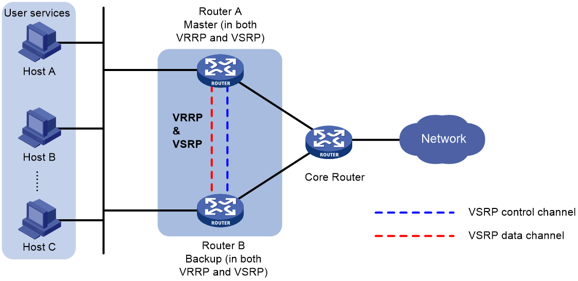
As shown in Figure 1, VSRP determines the roles of the peer devices in the VSRP group in consistent with their roles in the VRRP group. The master forwards traffic and backs up the services to the backup device either at a regular interval or when traffic reaches the specified threshold. When the master in the VSRP group fails, the backup takes over to ensure service continuity. For more information about VRRP, see "Configuring VRRP."
Figure 1 VSRP-VRRP collaboration
VSRP backup modes
A VSRP instance supports the following backup modes:
· Hot backup mode (1:1 backup)—The backup device issues backup data to the data plane as soon as it receives the data from the master. In this mode, the backup takes over quickly when the master fails. This mode is applicable to scenarios where a device acts as the backup in only one VSRP group.
VSRP provides the following hot backup modes:
¡ Dual-active hot backup mode—Both the master and backup devices are active to load share traffic.
¡ Single-active hot backup mode—The master device is active to process service traffic, and the backup device takes over when the master device fails.
· Warm backup mode (N:1 backup)—One backup device backs up multiple master devices. The backup device issues received backup data to the data plane when a master fails. This mode has a longer failover delay than hot backup mode. This mode is applicable to scenarios where a device acts as the backup in more than one VSRP group.
VSRP control channel fast detection
By default, a VSRP group detects the state of the failover link based only on the state of the TCP control channel. To fast detect the state of the failover link, you can perform the following tasks:
1. Use NQA or BFD to monitor the state of the failover link.
2. Establish the collaboration between the failover link state and NQA or BFD through the Track function.
A VSRP group operates differently depending on the state of the track entry associated with the VSRP group:
· When the track entry is in Positive or NotReady state, a device attempts to establish a TCP control channel with its peer.
· When the track entry changes to Negative state, the device terminates the TCP control channel.
Restrictions and guidelines: Subinterface configuration consistency
Use VSRP only in the CP and UP separation scenario.
As a best practice to maintain data consistency, make sure the peer devices in a VSRP group have consistent main interface and subinterface configuration, including but not limited to the following settings:
· Subinterface numbers.
· VLAN configuration.
· VPN configuration.
VSRP tasks at a glance
To configure VSRP, perform the following tasks:
2. Configuring a VSRP instance
3. Specifying a virtual IPv6 address
This task is required if you enable VSRP for IPoE or DHCPv6 on an IPv6 network.
4. Setting up protection tunnels
Prerequisites for VSRP
Perform the following tasks on the two peer devices in a VSRP group:
1. For VSRP to collaborate with VRRP, configure VRRP to operate in standard mode.
2. For VSRP to collaborate with VRRP, configure a VRRP group on the two peer devices to determine their role in the VSRP group.
|
|
NOTE: Binding a VSRP group to an existing VRRP group does not affect the functionality of the VRRP group. |
Configuring a VSRP group
1. Enter system view.
system-view
2. Create a VSRP group and enter the VSRP peer view.
vsrp peer peer-name
3. Configure TCP connection parameters for establishing VSRP channels to the peer.
peer [ ipv6 ] peer-ip-address local local-ip-address [ port port-id ]
By default, no VSRP channels are established to the peer.
The TCP port cannot be in use. To view the TCP port numbers in use, execute the display [ ipv6 ] tcp command.
4. (Optional.) Associate a VSRP group with a track entry.
track track-entry-number
Configuring a VSRP instance
About this task
A VSRP instance backs up data for its associated service.
A VSRP instance can be bound to only one VSRP group. Each VSRP instance on a VSRP group is identified by a unique backup ID.
The master forwards traffic and backs up service data to the backup device at the specified interval or when the specified traffic threshold is reached.
An IPoE or PPPoE network requires an address pool to be created on the master and backup of a VSRP instance and route advertisement for subnets of the address pool. By default, only the master advertises the subnet routes, and network devices reach terminal users only through the master. If the master fails or is disconnected, communication with the terminal users is interrupted before the backup takes over.
You can enable route advertisement for the backup to reduce the service outage. After you configure this feature, the network devices have two routes to reach a terminal user, and the route advertised by the master has a smaller route cost. When both the master and the backup are available, the network devices access terminal users through the master. When the master becomes unavailable, the network devices look up the routing table and use the routes advertised by the backup to reach terminal users.
Restrictions and guidelines
The NAS parameters (IP address, interface, and host name) on a VSRP instance are shared by the VSRP member devices for the associated service. Configure NAS settings on a VSRP instance if its associated service requires the NAS parameters to remain unchanged after a master/backup switchover. For example, the settings are applicable to the following scenarios:
· Avoid re-authentication on master/backup switchover by maintaining the same NAS-IP-address, NAS-Port, and host name in packets sent to the RADIUS server.
· Maintain the same Option 82 values in packets sent to the DHCP server.
Procedure
1. Enter system view.
system-view
2. Create a VSRP instance and enter VSRP instance view.
vsrp instance instance-name
3. Specify a backup ID for the VSRP instance.
backup id backup-id peer peer-name
By default, a VSRP instance has no ID.
4. Bind the VSRP instance to a VRRP group.
¡ Bind the VSRP instance to an IPv4 VRRP group.
bind vrrp vrid virtual-router-id interface interface-type interface-number
By default, a VSRP instance is not bound to an IPv4 VRRP group.
¡ Bind the VSRP instance to an IPv6 VRRP group.
bind vrrp ipv6 vrid virtual-router-id interface interface-type interface-number
By default, a VSRP instance is not bound to an IPv6 VRRP group.
If you execute the following commands multiple times for a VSRP instance, the most recent configuration takes effect:
¡ bind vrrp ipv6 vrid
¡ bind vrrp vrid
5. Set the backup mode of the VSRP instance.
backup mode { hot [ dual-active ] | warm }
By default, a VSRP instance operates in hot backup mode.
6. (Optional.) Set a traffic backup interval or a traffic threshold that triggers a traffic backup.
traffic backup { interval interval-value | threshold threshold-value } *
By default, a VSRP instance backs up traffic at 10-minute intervals or when the traffic reaches 50 MB.
7. (Optional.) Enable route advertisement for the backup.
backup route-advertise [ master-cost master-cost backup-cost backup-cost ]
By default, route advertisement is enabled only for the master.
8. (Optional.) Configure NAS parameters.
nas { id host-name | ip ip-address | port interface-type interface-number }
By default, no NAS parameters are configured.
Specifying a virtual IPv6 address
About this task
To enable VSRP for IPv6 services (such as IPoE and DHCPv6), you must specify a virtual IPv6 address for the service-enabled interface. This is applicable to some special networks, such as a network that contains BRAS devices. In a VSRP instance, you must configure the same virtual IPv6 address on the master and the backup. Then, the master advertises the virtual IPv6 address as the gateway address in RA messages to the hosts. In this way, traffic from the hosts can be directed to the master.
Procedure
1. Enter system view.
system-view
2. Enter interface view.
interface interface-type interface-number
The following types of interfaces are supported:
¡ Layer 3 Ethernet interface.
¡ Layer 3 Ethernet subinterface.
¡ Layer 3 aggregate interface.
¡ Layer 3 aggregate subinterface.
¡ Layer 3 FlexE logical interface.
3. Specify a virtual IPv6 address for the interface that is associated with a VSRP instance.
ipv6 virtual-address ipv6-address vsrp vsrp-instance
By default, no virtual IPv6 address is specified for the interface.
Setting up protection tunnels
About this task
To ensure service continuity when the access-side link of the master fails, the master forwards the traffic sent from the external network to users towards the backup over a protection tunnel. The backup then forwards the traffic to the destination.
The master and the backup set up protection tunnels for the public instance and each VPN instance. The protection tunnel for the public instance is set up after you finish protection tunnel configuration, while the protection tunnel for a VPN instance is set up on demand.
Restrictions and guidelines
VSRP supports LSP and SRv6 protection tunnels. The LSP protection tunnels can only be SR TE tunnels, and the SRv6 protection tunnels can only be SRv6 BE tunnels. For more information about SR TE tunnels, see SR-MPLS TE policy configuration in Segment Routing Configuration Guide. For more information about SRv6 BE tunnels, see SRv6 VPN configuration in Segment Routing Configuration Guide.
Procedure
1. Enter system view.
system-view
2. Create a VSRP group and enter VSRP peer view.
vsrp peer peer-name
3. Configure protection tunnels. Choose one of the following methods:
¡ Specify the destination address of LSP protection tunnels.
protect lsp-tunnel for-all-instance peer-ip ip-address [ tunnel-policy policy-name ]
By default, no LSP protection tunnel destination address is configured.
¡ Specify a locator for SRv6 protection tunnels.
protect srv6-tunnel for-all-instance locator locator-name
By default, no SRv6 protection tunnels exist.
Display and maintenance commands for VSRP
Execute display commands in any view.
|
Task |
Command |
|
Display VSRP instance information. |
display vsrp instance [ instance-name ] |
|
Display VSRP group information. |
display vsrp peer [ peer-name ] |
