- Table of Contents
-
- 14-High Availability Configuration Guide
- 00-Preface
- 01-Ethernet OAM configuration
- 02-CFD configuration
- 03-DLDP configuration
- 04-Monitor Link configuration
- 05-S-Trunk configuration
- 06-Error code detection configuration
- 07-VRRP configuration
- 08-VSRP configuration
- 09-Failover group configuration
- 10-Service instance group configuration
- 11-BFD configuration
- 12-Track configuration
- 13-Process placement configuration
- Related Documents
-
| Title | Size | Download |
|---|---|---|
| 02-CFD configuration | 461.47 KB |
Ethernet Alarm Indication Signal
Restrictions and guidelines: CFD configuration
Configuring basic CFD settings
Configuring MIP auto-generation rules
Configuring single-ended synthetic LM
Display and maintenance commands for CFD
Example: Configuring CFD in an Ethernet network
Example: Configuring CFD in a Layer 2 VPN (L2VPN networking)
Configuring CFD
About CFD
Connectivity Fault Detection (CFD), which conforms to IEEE 802.1ag Connectivity Fault Management (CFM) and ITU-T Y.1731, is an end-to-end link layer OAM mechanism. CFD is used for link connectivity detection, fault verification, and fault location in Ethernet networks and MPLS Layer 2 VPNs. For information about MPLS Layer 2 VPNs, see MPLS L2VPN and VPLS in MPLS Configuration Guide.
Basic CFD concepts
Maintenance domain
A maintenance domain (MD) defines the network or part of the network where CFD plays its role. An MD is identified by its MD name.
Maintenance association
A maintenance association (MA) is a part of an MD. You can configure multiple MAs in an MD as needed. An MA is identified by the MD name + MA name.
In an Ethernet network, an MA serves the specified VLAN or no VLAN. An MA that serves a VLAN is considered to be carrying VLAN attribute. An MA that serves no VLAN is considered to be carrying no VLAN attribute.
In an MPLS Layer 2 VPN, an MA can only serve the specified cross-connect or virtual switch instance (VSI).
Maintenance point
An MP is configured on a port and belongs to an MA. MPs include the following types: maintenance association end points (MEPs) and maintenance association intermediate points (MIPs).
MEPs define the boundary of the MA. Each MEP is identified by a MEP ID.
In an Ethernet network, the MA to which a MEP belongs defines the VLAN of packets sent by the MEP.
In an MPLS Layer 2 VPN, the MA to which a MEP belongs defines the cross-connect or VSI of packets sent by the MEP.
MEPs include inward-facing MEPs and outward-facing MEPs:
· An inward-facing MEP does not send packets to its host port. Rather, it sends packets to other ports on the device. In an Ethernet network, the packets are broadcast in the VLAN that the MA of the MEP serves. In an MPLS Layer 2 VPN, the packets are broadcast in the cross-connect or VSI to which the MEP belongs.
· An outward-facing MEP sends packets to its host port.
A MIP is internal to an MA. It cannot send CFD packets actively, but it can handle and respond to CFD packets. MIPs are automatically created by the device. By cooperating with MEPs, a MIP can perform a function similar to ping and traceroute.
The MA to which a MIP belongs defines the VLAN of packets that the MIP can receive.
The MIP-related configuration takes effect only in Ethernet networks.
MEP list
A MEP list is a collection of local MEPs allowed to be configured and the remote MEPs to be monitored in the same MA. It lists all the MEPs configured on different devices in the same MA. The MEPs all have unique MEP IDs. When a MEP receives from a remote device a continuity check message (CCM) carrying a MEP ID not in the MEP list of the MA, it drops the message.
The local device must send CCM messages carrying the Remote Defect Indication (RDI) flag bits. Otherwise, the peer device cannot sense certain failures. When a local MEP has not learned all remote MEPs in the MEP list, the MEPs in the MA might not carry the RDI flag bits in CCMs.
CFD levels
MD levels
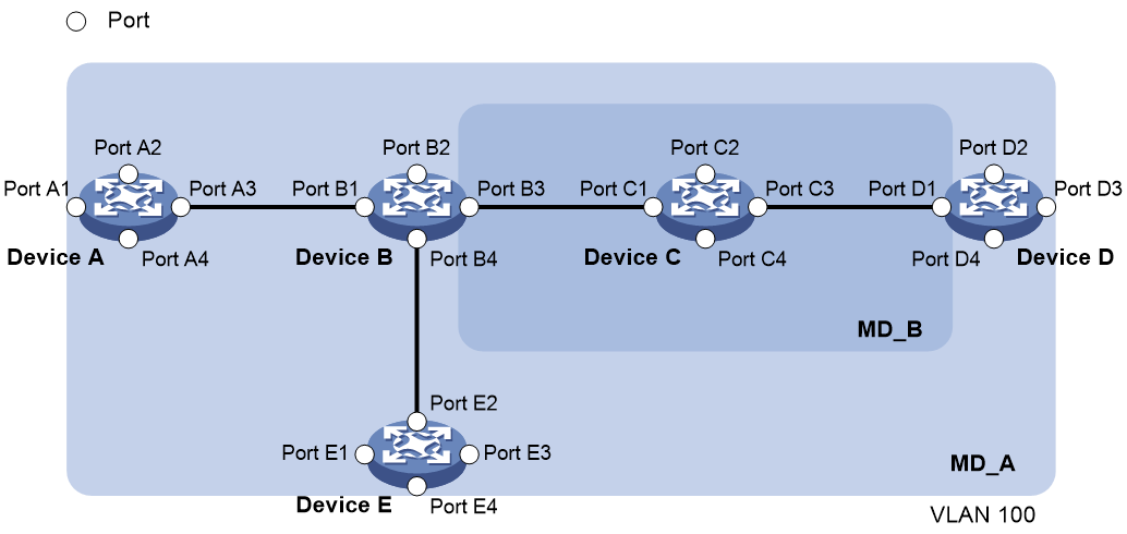
To accurately locate faults, CFD introduces eight levels (from 0 to 7) to MDs. The bigger the number, the higher the level and the larger the area covered. Domains can touch or nest (if the outer domain has a higher level than the nested one) but cannot intersect or overlap.
MD levels facilitate fault location and make fault location more accurate. As shown in Figure 1, MD_A in light blue nests MD_B in dark blue. If a connectivity fault is detected at the boundary of MD_A, any of the devices in MD_A, including Device A through Device E, might fail. If a connectivity fault is also detected at the boundary of MD_B, the failure points can be any of Device B through Device D. If the devices in MD_B can operate correctly, at least Device C is operational.
|
|
NOTE: This section assumes that physical links between devices are in good condition. |
CFD exchanges messages and performs operations on a per-domain basis. By planning MDs correctly in a network, you can use CFD to rapidly locate failure points.
MA and MP levels
The level of an MA equals the level of the MD to which the MA belongs.
The level of a MEP equals the level of the MD to which the MEP belongs.
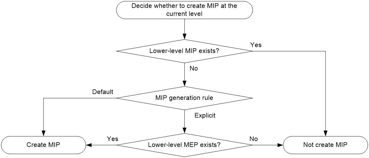
The level of a MIP is defined by its generation rule and the MD to which the MIP belongs. MIPs are generated on each port automatically according to the following MIP generation rules:
· Default rule—If no lower-level MIP exists on an interface, a MIP is created on the current level. A MIP can be created even if no MEP is configured on the interface.
· Explicit rule—If no lower-level MIP exists and a lower-level MEP exists on an interface, a MIP is created on the current level. A MIP can be created only when a lower-level MEP is created on the interface.
If a port has no MIP, the system will check the MAs in each MD (from low to high levels), and follow the procedure as described in Figure 2 to create or not to create MIPs at the current level.
Figure 2 Procedure of creating MIPs
CFD grading example
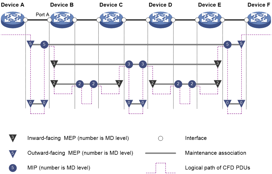
Figure 3 demonstrates a grading example of the CFD module. Four levels of MDs (0, 2, 3, and 5) are designed. The bigger the number, the higher the level and the larger the area covered. MPs are configured on the ports of Device A through Device F. Port A of Device B is configured with the following MPs:
· A level 5 MIP.
· A level 3 inward-facing MEP.
· A level 2 inward-facing MEP.
· A level 0 outward-facing MEP.
Packet processing of MPs
For an MA carrying VLAN attribute, MPs of the MA send packets only in the VLAN that the MA serves. The level of packets sent by an MP equals the level of the MD to which the MP belongs.
For an MA not carrying VLAN attribute, MPs of the MA can only be outward-facing MEPs. The level of packets sent by an outward-facing MEP equals the level of the MD to which the MEP belongs.
A MEP forwards packets at a higher level without any processing and only processes packets of its level or lower.
A MIP forwards packets of a different level without any processing and only processes packets of its level.
CFD functions
CFD functions, which are implemented through the MPs, include:
· Continuity check (CC).
· Loopback (LB).
· Linktrace (LT).
· Alarm indication signal (AIS).
· Loss measurement (LM).
· Delay measurement (DM).
· Test (TST).
Continuity check
Connectivity faults are usually caused by device faults or configuration errors. Continuity check examines the connectivity between MEPs. This function is implemented through periodic sending of CCMs by the MEPs. A CCM sent by one MEP is intended to be received by all the other MEPs in the same MA. If a MEP fails to receive the CCMs within 3.5 times the sending interval, the link is considered as faulty and a log is generated. When multiple MEPs send CCMs at the same time, the multipoint-to-multipoint link check is achieved. CCM frames are multicast frames.
Loopback
Similar to ping at the IP layer, loopback verifies the connectivity between a source device and a target device. To implement this function, the source MEP sends loopback messages (LBMs) to the target MEP. Depending on whether the source MEP can receive a loopback reply message (LBR) from the target MEP, the link state between the two can be verified.
LBM frames are multicast and unicast frames. The device can send and receive unicast LBM frames, and can receive multicast LBM frames but cannot send multicast LBM frames. LBR frames are unicast frames.
Linktrace
Linktrace is similar to traceroute. It identifies the path between the source MEP and the target MP. The source MEP sends the linktrace messages (LTMs) to the target MP. After receiving the messages, the target MP and the MIPs that the LTM frames pass send back linktrace reply messages (LTRs) to the source MEP. Based on the reply messages, the source MEP can identify the path to the target MP. LTM frames are multicast frames and LTRs are unicast frames.
AIS
The AIS function suppresses the number of error alarms reported by MEPs. If a local MEP does not receive any CCM frames from its peer MEP within 3.5 times the CCM transmission interval, it immediately starts sending AIS frames. The AIS frames are sent periodically in the opposite direction of CCM frames. When the peer MEP receives the AIS frames, it suppresses the error alarms locally, and continues to send the AIS frames. If the local MEP receives CCM frames within 3.5 times the CCM transmission interval, it stops sending AIS frames and restores the error alarm function. AIS frames are multicast frames.
This function can be configured only in Ethernet networks.
LM
The loss measurement (LM) function measures the frame loss between a pair of MEPs, including the following types:
· One-way LM—The source MEP sends loss measurement messages (LMMs) to the target MEP. The target MEP responds with loss measurement replies (LMRs). The source MEP calculates the number of lost frames according to the counter values of the two consecutive LMRs (the current LMR and the previous LMR). LMMs and LMRs are unicast frames.
The one-way LM function can be implemented in one of the following ways:
¡ Short-period LM—The source MEP sends a configurable number of LMMs at a configurable interval. The test result is printed when the test ends.
¡ Continual LM—The source MEP continually sends LMMs at a configurable interval until continual LM is administratively disabled. To view the test result, use the display cfd slm history command on the target MEP.
¡ Scheduled LM—Performs one-way LM based on the specified duration. The source MEP sends LMMs at a configurable interval until the specified duration timer expires. To view the test result, use the display cfd slm history command on the target MEP.
· Two-way LM—The source MEP sends CCMs to the target MEP. The target MEP responds with CCMs. The source MEP calculates the number of lost frames according to the counter values of the two consecutive CCMs received (the current CCM and the previous CCM).
The two-way LM function is implemented as continual LM. The number of frames received and the number of frames sent are padded in the CCMs sent by the source MEP. After you disable two-way LM, the device no longer pads the number of frames received or sent in the CCMs. To view the test result, use the display cfd dlm history command on the target MEP.
· Single-ended synthetic LM—The source MEP sends single loss measurement messages (SLMs) to the target MEP. The target MEP responds with single loss measurement replies (SLRs). The source MEP calculates the number of lost frames according to the number of sent SLMs and the number of received SLRs. SLMs and SLRs are unicast frames.
The single-ended synthetic LM function can be implemented in one of the following ways:
¡ Short-period LM—The source MEP sends a configurable number of SLMs at a configurable interval. The test result is printed when the test ends.
¡ Continual LM—The source MEP continually sends SLMs at a configurable interval until continual LM is administratively disabled. To view the test result, use the display cfd synthetic-slm history command on the target MEP.
¡ Scheduled LM—Performs single-ended synthetic LM based on the specified duration. The source MEP sends SLMs at a configurable interval until the specified duration timer expires. To view the test result, use the display cfd synthetic-slm history command on the target MEP.
DM
The DM function measures frame delays between two MEPs, including the following types:
· One-way frame delay measurement
The source MEP sends a one-way delay measurement (1DM) frame, which carries the transmission time, to the target MEP. When the target MEP receives the 1DM frame, it does the following:
¡ Records the reception time.
¡ Calculates and records the link transmission delay and jitter (delay variation) according to the transmission time and reception time.
1DM frames are unicast frames.
The one-way DM function can be implemented in one of the following ways:
¡ Short-period DM—The source MEP sends a configurable number of 1DM frames at a configurable interval. To view the test result, use the display cfd dm one-way history command on the target MEP.
¡ Continual DM—The source MEP continually sends 1DM frames at a configurable interval until continual DM is administratively disabled. To view the test result, use the display cfd dm one-way history command on the target MEP.
¡ Scheduled DM—Performs one-way DM based on the specified duration. The source MEP sends 1DM frames at a configurable interval until the specified duration timer expires. To view the test result, use the display cfd dm one-way history command on the target MEP.
· Two-way frame delay measurement
The source MEP sends a delay measurement message (DMM), which carries the transmission time, to the target MEP. When the target MEP receives the DMM, it responds with a delay measurement reply (DMR). The DMR carries the reception time and transmission time of the DMM and the transmission time of the DMR. When the source MEP receives the DMR, it does the following:
¡ Records the DMR reception time.
¡ Calculates the link transmission delay and jitter according to the DMR reception time and DMM transmission time.
DMM frames and DMR frames are unicast frames.
The two-way DM function can be implemented in one of the following ways:
¡ Short-period DM—The source MEP sends a configurable number of DMMs at a configurable interval. The test result is printed when the test ends.
¡ Continual DM—The source MEP continually sends DMMs at a configurable interval until continual DM is administratively disabled. To view the test result, use the display cfd dm two-way history command on the target MEP.
¡ Scheduled DM—Performs one-way DM based on the specified duration. The source MEP sends DMMs at a configurable interval until the specified duration timer expires. To view the test result, use the display cfd dm two-way history command on the target MEP.
TST
The TST function tests the bit errors between two MEPs. The source MEP sends a TST frame, which carries the test pattern, such as pseudo random bit sequence (PRBS) or all-zero, to the target MEP. When the target MEP receives the TST frame, it determines the bit errors by calculating and comparing the content of the TST frame. TST frames are unicast frames.
This function can be configured only in Ethernet networks.
Threshold alarm
The threshold alarm function monitors the transmission performance of links. The system generates an alarm when the transmission performance metric of a link crosses the specified upper limit or lower limit three times in succession.
Ethernet Alarm Indication Signal
Ethernet Alarm Indication Signal (EAIS) enables collaboration between the Ethernet port status and the AIS function. When a port on the device (not necessarily an MP) goes down, it immediately starts to send EAIS frames periodically to suppress the error alarms. When the port goes up again, it immediately stops sending EAIS frames. When the MEP receives the EAIS frames, it suppresses the error alarms locally, and continues to send the EAIS frames. If a MEP receives no EAIS frames within 3.5 times the EAIS frame transmission interval, the fault is considered cleared. The port stops sending EAIS frames and restores the error alarm function. EAIS frames are multicast frames.
This function takes effect only in Ethernet networks.
Protocols and standards
· IEEE 802.1ag, Virtual Bridged Local Area Networks Amendment 5: Connectivity Fault Management
· ITU-T Y.1731, OAM functions and mechanisms for Ethernet based networks
Restrictions and guidelines: CFD configuration
When you configure CFD, follow these restrictions and guidelines:
· Configure CC before you use the MEP ID of the remote MEP to configure other CFD functions. This restriction does not apply when you use the MAC address of the remote MEP to configure other CFD functions.
· Typically, a port blocked by the spanning tree feature cannot receive or send CFD messages except in the following cases:
¡ The port is configured as an outward-facing MEP.
¡ The port is configured as a MIP or inward-facing MEP, which can still receive and send CFD messages except CCM messages.
For more information about the spanning tree feature, see Layer 2—LAN Switching Configuration Guide.
This feature is available only for the following cards:
|
Card category |
Cards |
|
CEPC |
CEPC-XP4LX, CEPC-XP24LX, CEPC-XP48RX, CEPC-CP4RX, CEPC-CP4RXA, CEPC-CP4RX-L, CEPC-CQ8L, CEPC-CQ8LA, CEPC-CQ8L1A, CEPC-CQ16L1 |
|
CSPEX |
CSPEX-1304X, CSPEX-1404X, CSPEX-1502X, CSPEX-1504X, CSPEX-1504XA, CSPEX-1602X, CSPEX-1602XA, CSPEX-1804X, CSPEX-1512X, CSPEX-1612X, CSPEX-1812X, CSPEX-1802X, CSPEX-1802XA, CSPEX-2612XA, CSPEX-1812X-E, CSPEX-2304X-G, CSPEX-1502XA |
|
SPE |
RX-SPE200, RX-SPE200-E |
In Layer 2 VPN networks, in standard system operating mode, this feature is available only for the following cards:
|
Card category |
Cards |
|
CEPC |
CEPC-CQ8L, CEPC-CQ8LA, CEPC-CQ8L1A, CEPC-CQ16L1 |
|
CSPEX |
CSPEX-1802X, CSPEX-1802XA, CSPEX-2612XA, CSPEX-1812X-E, CSPEX-2304X-G, CSPEX-1502XA |
|
SPE |
RX-SPE200-E |
In EVPN VPWS or EVPN VPWS over SRv6 multihomed networks, if CFD is enabled, you can only set single-active redundancy mode for interfaces or UPWs. In single-active redundancy mode, only the primary link supports CFD.
In EVPN VPLS or EVPN VPLS over SRv6 multihomed networks, if CFD is enabled, you can set single-active or all-active redundancy mode for interfaces or UPWs. In single-active redundancy mode, only the primary link supports CFD. In all-active redundancy mode, one-way LM and two-way LM are not supported.
For more information about the redundancy mode of interfaces or UPWs, see EVPN commands in EVPN Command Reference.
In a VPLS network, if CFD is enabled, you cannot specify the static MAC address of the AC interface as the bridge MAC address of the local device or remote device.
CFD tasks at a glance
To configure CFD, perform the following tasks:
1. Configuring basic CFD settings
a. Enabling CFD
b. Configuring service instances
d. Configuring MIP auto-generation rules
b. (Optional.) Configuring LB
c. (Optional.) Configuring LT
d. (Optional.) Configuring AIS
e. (Optional.) Configuring one-way LM
f. (Optional.) Configuring two-way LM
g. (Optional.) Configuring single-ended synthetic LM
h. (Optional.) Configuring one-way DM
i. (Optional.) Configuring two-way DM
j. (Optional.) Configuring TST
k. (Optional.) Configuring threshold alarm
3. (Optional.) Configuring EAIS
Prerequisites for CFD
For CFD to work correctly, design the network by performing the following tasks:
· Grade the MDs in the entire network, and define the boundary of each MD.
· Assign a name for each MD. Make sure the devices in the same MD use the same MD name.
· Define the MA in each MD according to the VLAN, cross-connect, or VSI you want to monitor.
· Assign a name for each MA. Make sure that the devices in the same MA in the same MD use the same MA name.
· Determine the MEP list of each MA in each MD. Make sure devices in the same MA maintain the same MEP list.
· At the edges of MD and MA, MEPs must be designed at the device port. MIPs can be designed on devices or ports that are not at the edges in Ethernet networks.
Configuring basic CFD settings
Enabling CFD
1. Enter system view.
system-view
2. Enable CFD.
cfd enable
By default, CFD is disabled.
Configuring service instances
About this task
Before configuring the MEPs and MIPs, you must first configure service instances. A service instance is a set of service access points (SAPs), and belongs to an MA in an MD.
In an Ethernet network, the MD and MA define the level attribute and VLAN attribute of the messages handled by the MPs in a service instance. The MPs of the MA that carries no VLAN attribute do not belong to any VLAN.
In an MPLS Layer 2 VPN, for the messages handled by the MEPs in a service instance, the MD and MA define the level attribute and cross-connect or VSI attribute, respectively.
Procedure
1. Enter system view.
system-view
2. Create an MD.
cfd md md-name [ index index-value ] level level-value [ md-id { dns dns-name | mac mac-address subnumber | none } ]
3. Create a service instance.
¡ In an Ethernet network:
cfd service-instance instance-id ma-id { icc-based ma-name | integer ma-num | string ma-name | vlan-based [ vlan-id ] } [ ma-index index-value ] md md-name [ vlan vlan-id ]
¡ In an MPLS Layer 2 VPN:
cfd service-instance instance-id ma-id { icc-based ma-name | integer ma-num | string ma-name } [ ma-index index-value ] md md-name { xconnect-group group-name connection connection-name | vsi vsi-name }
Configuring MEPs
About this task
CFD is implemented through various operations on MEPs. As a MEP is configured on a service instance, the MD level and VLAN attribute or cross-connect or VSI attribute of the service instance become the attributes of the MEP.
Restrictions and guidelines
In an Ethernet network:
· You can specify an interface as the MEP for only one of the non-VLAN-specific MAs at the same level. In addition, the MEP must be outward facing.
On a Layer 3 Ethernet interface, you cannot create a MEP for an MA that carries VLAN attribute.
In an MPLS Layer 2 VPN:
· You can configure only one inward-facing MEP for a CFD service instance.
· An inward-facing MEP can only be configured on an AC interface to detect PW or AC connectivity.
· To specify the VLAN ID when creating a MEP, you must first configure the vlan-type dot1q vid vlan-id-list command and set the same value for the vlan-id-list and vlan vlan-id parameters. For more information about the vlan-type dot1q vid vlan-id-list command, see VLAN termination commands in Layer 2—LAN Switching Command Reference.
· To specify the outer and inner VLAN IDs when creating a MEP, you must first configure the vlan-type dot1q vid second-dot1q command and set the same outer VLAN ID and the same inner VLAN ID in the two commands. For more information about the vlan-type dot1q vid second-dot1q command, see VLAN termination commands in Layer 2—LAN Switching Command Reference.
Prerequisites
Before you configure MEPs, you must configure service instances.
Configuring MEPs in an Ethernet network
1. Enter system view.
system-view
2. Configure a MEP list.
cfd meplist mep-list service-instance instance-id
The created MEP must be included in the configured MEP list.
3. Enter interface view.
interface interface-type interface-number
4. Create a MEP.
¡ Create a MEP in Layer 2 Ethernet interface view, Layer 2 FlexE logical interface view, or Layer 2 aggregate interface view.
cfd mep mep-id service-instance instance-id { inbound | outbound }
¡ Create a MEP in Layer 3 Ethernet interface view or Layer 3 FlexE logical interface view.
cfd mep mep-id service-instance instance-id outbound
Configuring MEPs in an MPLS Layer 2 VPN
1. Enter system view.
system-view
2. Configure a MEP list.
cfd meplist mep-list service-instance instance-id
The created MEP must be included in the configured MEP list.
3. Enter interface view.
¡ Enter Layer 3 Ethernet interface, Layer 3 FlexE logical interface, or Layer 3 aggregate interface view.
interface interface-type interface-number
¡ Enter Layer 3 Ethernet subinterface or Layer 3 aggregate subinterface view.
interface interface-type interface-number.subnumber
4. Create a MEP.
¡ In Layer 3 aggregate interface view or Layer 3 aggregate subinterface view:
cfd mep mep-id service-instance instance-id inbound
¡ In Layer 3 Ethernet interface view:
cfd mep mep-id service-instance instance-id { inbound | outbound }
¡ In Layer 3 Ethernet subinterface view or Layer 3 FlexE logical interface view:
cfd mep mep-id service-instance instance-id inbound
cfd mep mep-id service-instance instance-id [ vlan vlan-id | service-vid vlan-id customer-vid vlan-id ] outbound
Configuring MIP auto-generation rules
About this task
As functional entities in a service instance, MIPs respond to various CFD frames, such as LTM and LBM frames. You can configure MIP auto-generation rules for the system to automatically create MIPs.
Any of the following events can cause MIPs to be created or deleted after you have configured the cfd mip-rule command:
· Enabling or disabling CFD.
· Creating or deleting MEPs on a port.
· Changes occur to the VLAN attribute of a port.
· The rule specified in the cfd mip-rule command changes.
Restrictions and guidelines
· An MA carrying no VLAN attribute is typically used to detect direct link status. The system cannot generate MIPs for such MAs.
· For an MA carrying VLAN attribute, the system does not generate MIPs if the same or a higher level MEP exists on the interface.
· The MIP-related configuration takes effect only in Ethernet networks.
Procedure
1. Enter system view.
system-view
2. Configure MIP auto-generation rules.
cfd mip-rule { default | explicit } service-instance instance-id
By default, no rules for generating MIPs are configured, and the system does not automatically create any MIP.
Configuring CFD functions
Configuring CC
About this task
After the CC function is configured, MEPs in an MA can periodically send CCM frames to maintain connectivity. When the lifetime of a CCM frame expires, the link to the sending MEP is considered disconnected. When setting the CCM interval, use the settings described in Table 1.
Table 1 CCM interval field encoding
|
CCM interval field |
Transmission interval |
Maximum CCM lifetime |
|
1 |
10/3 milliseconds |
35/3 milliseconds |
|
2 |
10 milliseconds |
35 milliseconds |
|
3 |
100 milliseconds |
350 milliseconds |
|
4 |
1 second |
3.5 seconds |
|
5 |
10 seconds |
35 seconds |
|
6 |
60 seconds |
210 seconds |
|
7 |
600 seconds |
2100 seconds |
|
|
NOTE: · The CCM messages with an interval field value of 1 to 3 are short-interval CCM messages. The CCM messages with an interval field value of 4 to 7 are long-interval CCM messages. |
Restrictions and guidelines
When you configure the CCM interval, follow these restrictions and guidelines:
· Configure the same CCM interval field value for all MEPs in the same MA.
· After the CCM interval field is modified, the MEP that does not support hardware CC must wait for another CCM interval before sending CCMs.
· If the device cannot process short-interval CCM messages, setting the CCM interval field value to smaller than 4 might cause the CC function to operate unsteadily.
When you configure hardware CC, follow these restrictions and guidelines:
· In an Ethernet network, the CCM interval field value must be greater than or equal to 3.
· In a Layer 2 VPN, you must configure hardware CC if the CCM interval field value is smaller than or equal to 4.
Configuring CC in an Ethernet network
1. Enter system view.
system-view
2. (Optional.) Set the CCM interval field.
cfd cc interval interval-value service-instance instance-id
By default, the interval field value is 4.
3. Enter Layer 2 or Layer 3 Ethernet interface view or Layer 2 aggregate interface view.
interface interface-type interface-number
4. Enable CCM sending on a MEP.
cfd cc service-instance instance-id mep mep-id enable
By default, CCM sending is disabled on a MEP.
Configuring CC in an MPLS Layer 2 VPN
1. Enter system view.
system-view
2. (Optional.) Set the CCM interval field.
cfd cc interval interval-value service-instance instance-id
By default, the interval field value is 4.
3. Enter interface view.
¡ Enter Layer 3 Ethernet interface, Layer 3 FlexE logical interface, or Layer 3 aggregate interface view.
interface interface-type interface-number
¡ Enter Layer 3 Ethernet subinterface or Layer 3 aggregate subinterface view.
interface interface-type interface-number.subnumber
4. Enable CCM sending on a MEP.
cfd cc service-instance instance-id mep mep-id enable
By default, CCM sending is disabled on a MEP.
5. (Optional.) Enable hardware CC on for remote MEPs.
cfd hardware-cc service-instance instance-id remote-mep mep-list
By default, hardware CC is disabled for a remote MEP.
Configuring LB
To verify the link state between the local MEP and the remote MEP, execute the following command in any view:
cfd loopback service-instance instance-id mep mep-id { target-mac mac-address | target-mep target-mep-id } [ number number ]
Configuring LT
About this task
LT can trace the path between source and target MEPs, and can locate link faults by automatically sending LT messages. The two functions are implemented in the following way:
· Tracing path—The source MEP first sends LTM messages to the target MEP. Based on the LTR messages in response to the LTM messages, the path between the two MEPs is identified.
· LT messages automatic sending—If the source MEP fails to receive CCM frames from the target MEP within 3.5 times the transmission interval, it considers the link faulty. The source MEP then sends LTM frames, with the TTL field set to the maximum value 255, to the target MEP. Based on the returned LTRs, the fault source is located.
Prerequisites
In an Ethernet network, before you configure LT on a MEP in an MA carrying VLAN attribute, create the VLAN to which the MA belongs.
In an MPLS Layer 2 VPN, before you configure LT on a MEP in an MA, create the cross-connect or VSI to which the MA belongs.
Procedure
1. Identify the path between a source MEP and a target MEP.
cfd linktrace service-instance instance-id mep mep-id { target-mac mac-address | target-mep target-mep-id } [ ttl ttl-value ] [ hw-only ]
This command is available in any view.
2. Enter system view.
system-view
3. Enable LT messages automatic sending.
cfd linktrace auto-detection [ size size-value ]
By default, LT messages automatic sending is disabled.
Configuring AIS
About this task
The AIS function suppresses the number of error alarms reported by MEPs.
Restrictions and guidelines
If you enable AIS without configuring a correct AIS frame transmission level, the MEP can suppress error alarms, but cannot send AIS frames to MDs with higher level.
This function can be configured only in Ethernet networks.
Procedure
1. Enter system view.
system-view
2. Enable AIS.
cfd ais enable
By default, AIS is disabled.
3. Configure the AIS frame transmission level.
cfd ais level level-value service-instance instance-id
By default, the AIS frame transmission level is not configured.
The AIS frame transmission level must be higher than the MD level of the service instance.
4. Configure the AIS frame transmission interval.
cfd ais period period-value service-instance instance-id
By default, the AIS frame transmission interval is 1 second.
Configuring one-way LM
About this task
The one-way LM function measures frame loss between MEPs. Frame loss statistics include the number of lost frames, the frame loss ratio, and the average number of lost frames for the target MEPs.
Restrictions and guidelines
To configure one-way LM in a Layer 2 VPN, first configure the same frame counting mode on the source MEP and target MEP.
Inward-facing MEPs created in an Ethernet network do not support one-way continual LM.
Configuring the frame counting mode
1. Enter system view.
system-view
2. Enter interface view.
¡ Enter Layer 3 Ethernet interface, Layer 3 FlexE logical interface, or Layer 3 aggregate interface view.
interface interface-type interface-number
¡ Enter Layer 3 Ethernet subinterface or Layer 3 aggregate subinterface view.
interface interface-type interface-number.subnumber
3. Configure the frame counting mode.
cfd frame-count mode { dot1p-based | port-based }
By default, no frame counting mode is configured for LM.
This command takes effect only in Layer 2 VPNs.
Configuring short-period LM
To configure short-period LM, execute the following command in any view:
cfd slm service-instance instance-id mep mep-id { target-mac mac-address | target-mep target-mep-id } [ peer ip-address pw-id pw-id ] [ dot1p dot1p-value ] [ number number ] [ interval { interval | msec msec-interval } ]
Configuring continual LM
1. Enter system view.
system-view
2. Configure continual LM
cfd slm continual service-instance instance-id mep mep-id { target-mac mac-address | target-mep target-mep-id } [ peer ip-address pw-id pw-id ] [ dot1p dot1p-value ] [ interval { interval | msec msec-interval }][ period period ]
By default, continual LM is not configured.
Configuring scheduled LM
To configure scheduled LM, execute the following command in any view:
cfd slm duration duration-time start service-instance instance-id mep mep-id { target-mac mac-address | target-mep target-mep-id } [ peer ip-address pw-id pw-id ] [ dot1p dot1p-value ] [ interval { interval | msec msec-interval }]
Configuring two-way LM
About this task
The two-way LM function measures bidirectional frame loss between MEPs. Frame loss statistics include the number of lost frames, the frame loss ratio, and the average number of lost frames for the source and target MEPs.
Restrictions and guidelines
For the two-way LM function to take effect, you must configure it on both the local and peer devices.
The two-way LM detection interval is the CCM interval. Before configuring two-way LM, configure the CCM interval field value to be greater than 2.
Two-way LM can be configured only in Layer 2 VPNs.
To configure two-way LM, first configure the same frame counting mode on the source MEP and target MEP.
Procedure
1. Enter system view.
system-view
2. Enter interface view.
¡ Enter Layer 3 Ethernet interface or Layer 3 aggregate interface view.
interface interface-type interface-number
¡ Enter Layer 3 Ethernet subinterface or Layer 3 aggregate subinterface view.
interface interface-type interface-number.subnumber
3. Configure the frame counting mode.
cfd frame-count mode { dot1p-based | port-based }
By default, no frame counting mode is configured.
4. Return to system view.
quit
5. Configure continual LM
cfd dlm continual service-instance instance-id mep mep-id { target-mac mac-address | target-mep target-mep-id } [ peer ip-address pw-id pw-id ] [ dot1p dot1p-value ]
By default, continual LM is not configured.
Configuring single-ended synthetic LM
About this task
The single-ended synthetic LM function measures the one-way frame loss between two MEPs, including the number of sent frames, the number of lost frames, average frame loss ratio, maximum. frame loss ratio, and minimum frame loss ratio.
Restrictions and guidelines
This function is supported only in EVPN VPLS, EVPN VPWS, MPLS L2VPN, and VPLS networks.
This function does not require the configuration of the frame counting mode.
Configuring short-period LM
To configure short-period LM, execute the following command in any view:
cfd synthetic-slm service-instance instance-id mep mep-id { target-mac mac-address | target-mep target-mep-id } [ number number ] [ interval msec-interval ]
Configuring continual LM
1. Enter system view.
system-view
2. Configure continual LM.
cfd synthetic-slm continual service-instance instance-id mep mep-id { target-mac mac-address | target-mep target-mep-id } [ number number ] [ interval msec-interval ]
By default, continual LM is not configured.
Configuring scheduled LM
To configure scheduled LM, execute the following command in any view:
cfd synthetic-slm duration duration-time start service-instance instance-id mep mep-id { target-mac mac-address | target-mep target-mep-id } [ number number ] [ interval msec-interval ]
Configuring one-way DM
About this task
The one-way DM function measures the one-way frame delay between two MEPs, and monitors and manages the link transmission performance.
Restrictions and guidelines
One-way DM requires that the time setting at the source MEP and the target MEP be the same. For the purpose of frame delay variation measurement, the requirement can be relaxed.
To view the test result, use the display cfd dm one-way history command on the target MEP.
Inward-facing MEPs created in an Ethernet network do not support one-way continual DM.
Configuring short-period DM
To configure short-period DM, execute the following command in any view:
cfd dm one-way service-instance instance-id mep mep-id { target-mac mac-address | target-mep target-mep-id } [ peer ip-address pw-id pw-id ] [ dot1p dot1p-value ] [ number number ] [ interval interval ]
Configuring continual DM
1. Enter system view.
system-view
2. Configure continual DM
cfd dm one-way continual service-instance instance-id mep mep-id { target-mac mac-address | target-mep target-mep-id } [ peer ip-address pw-id pw-id ] [ dot1p dot1p-value ][ interval interval ]
By default, continual DM is not configured.
Configuring scheduled DM
To configure scheduled DM, execute the following command in any view:
cfd dm one-way duration duration-time start service-instance instance-id mep mep-id { target-mac mac-address | target-mep target-mep-id } [ peer ip-address pw-id pw-id ] [dot1p dot1p-value ] [ interval interval ]
Configuring two-way DM
About this task
The two-way DM function measures the two-way frame delay, average two-way frame delay, and two-way frame delay variation between two MEPs. It also monitors and manages the link transmission performance.
Restrictions and guidelines
Inward-facing MEPs created in an Ethernet network do not support two-way continual DM.
Configuring short-period DM
To configure short-period DM, execute the following command in any view:
cfd dm two-way service-instance instance-id mep mep-id { target-mac mac-address | target-mep target-mep-id } [ peer ip-address pw-id pw-id ] [ dot1p dot1p-value ] [ number number ] [ interval interval ]
Configuring continual DM
1. Enter system view.
system-view
2. Configure continual DM.
cfd dm two-way continual service-instance instance-id mep mep-id { target-mac mac-address | target-mep target-mep-id } [ peer ip-address pw-id pw-id ] [ dot1p dot1p-value ] [ interval interval ]
By default, continual DM is not configured.
Configuring scheduled DM
To configure scheduled DM, execute the following command in any view:
cfd dm two-way duration duration-time start service-instance instance-id mep mep-id { target-mac mac-address | target-mep target-mep-id } [ peer ip-address pw-id pw-id ] [dot1p dot1p-value ] [ interval interval ]
Configuring TST
About this task
The TST function detects bit errors on a link, and monitors and manages the link transmission performance.
Restrictions and guidelines
To view the test result, use the display cfd tst history command on the target MEP.
This function can be configured only in Ethernet networks.
Inward-facing MEPs created in an Ethernet network do not support this function.
Configuring short-period TST
To configure short-period TST, execute the following command in any view:
cfd tst service-instance instance-id mep mep-id { target-mac mac-address | target-mep target-mep-id } [ number number ] [ length-of-test length ] [ pattern-of-test { all-zero | prbs } [ with-crc ] ]
Configuring continual TST
1. Enter system view.
system-view
2. Configure continual TST
cfd tst continual service-instance instance-id mep mep-id { target-mac mac-address | target-mep target-mep-id } [ length-of-test length ] [ pattern-of-test { all-zero | prbs } [ with-crc ] ] [ interval interval ]
By default, continual TST is not configured.
Configuring threshold alarm
About this task
The threshold alarm function allows you to monitor the packet loss ratio, delay, and bit error rate of MEPs and view the monitoring results.
Restrictions and guidelines
The lower limit must be smaller than the upper limit.
Configuring threshold alarm for continual one-way LM
1. Enter system view.
system-view
2. Configure threshold alarm for continual LM.
cfd slm { far-end | near-end } threshold service-instance instance-id mep mep-id { lower-limit lower-limit | upper-limit upper-limit }
This command takes effect only after you configure continual one-way LM.
Configuring threshold alarm for continual two-way LM
1. Enter system view.
system-view
2. Configure threshold alarm for continual two-way LM.
cfd dlm { far-end | near-end } threshold service-instance instance-id mep mep-id { lower-limit lower-limit | upper-limit upper-limit }
This command takes effect only after you configure continual two-way LM.
Configuring threshold alarm for single-ended synthetic LM
1. Enter system view.
system-view
2. Configure threshold alarm for single-ended synthetic LM.
cfd synthetic-slm { far-end | near-end } threshold service-instance instance-id mep mep-id { target-mac mac-address | target-mep target-mep-id } { lower-limit lower-limit | upper-limit upper-limit }
This command takes effect only after you configure single-ended synthetic LM.
Configuring threshold alarm for continual two-way DM
1. Enter system view.
system-view
2. Configure threshold alarm for continual two-way DM.
cfd dm two-way threshold service-instance instance-id mep mep-id { lower-limit lower-limit | upper-limit upper-limit }
This command takes effect only after you configure continual two-way DM.
Configuring EAIS
Restrictions and guidelines
You can configure EAIS on a device that does not support or is not configured with CFD. However, EAIS must collaborate with the CFD function in the network, so you must configure CFD in the network.
The EAIS configuration on a member port of an aggregation group takes effect only after the port leaves the aggregation group.
If the intersection of the configured VLANs where the EAIS frames can be transmitted and the VLANs to which the port belongs is empty, no EAIS frame is sent. If the intersection contains more than 70 VLANs and the EAIS frame transmission interval is 1 second, the CPU usage will be too high. As a best practice, set the EAIS frame transmission interval to 60 seconds in this case.
This function takes effect only in Ethernet networks.
Procedure
1. Enter system view.
system-view
2. Enable port status-AIS collaboration.
cfd ais-track link-status global
By default, port status-AIS collaboration is disabled.
3. Enter Layer 2 Ethernet interface view, Layer 2 FlexE logical interface view, or Layer 2 aggregate interface view.
interface interface-type interface-number
4. Configure the EAIS frame transmission level.
cfd ais-track link-status level level-value
By default, the EAIS frame transmission level is not configured.
5. Configure the EAIS frame transmission interval.
cfd ais-track link-status period period-value
By default, the EAIS frame transmission interval is not configured.
6. Specify the VLANs where the EAIS frames can be transmitted.
cfd ais-track link-status vlan vlan-list
By default, the EAIS frames can only be transmitted within the default VLAN of the port.
The EAIS frames are transmitted within the intersection of the VLANs specified with this command and the existing VLANs on the device.
Display and maintenance commands for CFD
Execute display commands in any view and reset commands in user view.
|
Task |
Command |
|
Display the AIS configuration and information on the specified MEP. |
display cfd ais [ service-instance instance-id [ mep mep-id ] ] |
|
Display the AIS configuration and information associated with the status of the specified port. |
display cfd ais-track link-status [ interface interface-type interface-number ] |
|
Display the two-way LM result on the specified MEP. |
display cfd dlm history [ service-instance instance-id [ mep mep-id ] ] [ number number ] |
|
Display the one-way DM result on the specified MEP. |
display cfd dm one-way history [ service-instance instance-id [ mep mep-id ] ] [ number number ] |
|
Display the one-way DM packet statistics. |
display cfd dm one-way statistics [ service-instance instance-id [ mep mep-id ] ] |
|
Display the two-way DM result on the specified MEP. |
display cfd dm two-way history [ service-instance instance-id [ mep mep-id ] ] [ number number ] |
|
Display the two-way DM packet statistics. |
display cfd dm two-way statistics [ service-instance instance-id [ mep mep-id ] ] |
|
Display LTR information received by a MEP. |
display cfd linktrace-reply [ service-instance instance-id [ mep mep-id ] ] |
|
Display the content of the LTR messages received as responses to the automatically sent LTMs. |
display cfd linktrace-reply auto-detection [ size size-value ] |
|
Display MD configuration information. |
display cfd md |
|
Display the attribute and running information of the MEPs. |
display cfd mep mep-id service-instance instance-id |
|
Display MEP lists in a service instance. |
display cfd meplist [ service-instance instance-id ] |
|
Display MP information. |
display cfd mp [ interface interface-type interface-number ] |
|
Display information about a remote MEP. |
display cfd remote-mep service-instance instance-id mep mep-id |
|
Display service instance configuration information. |
display cfd service-instance [ instance-id ] |
|
Display the one-way LM result on the specified MEP. |
display cfd slm history [ service-instance instance-id [ mep mep-id ] ] [ number number ] |
|
Display the one-way LM packet statistics. |
display cfd slm statistics [ service-instance instance-id [ mep mep-id ] ] |
|
Display CFD status. |
display cfd status |
|
Display the single-ended synthetic LM result on the specified MEP. |
display cfd synthetic-slm history [ service-instance instance-id [ mep mep-id [ target-mac mac-address | target-mep target-mep-id ] ] ] [ number number ] |
|
Display the TST result on the specified MEP. |
display cfd tst history [ service-instance instance-id [ mep mep-id ] ] [ number number ] |
|
Clear the two-way LM result on the specified MEP. |
reset cfd dlm history [ service-instance instance-id [ mep mep-id ] ] |
|
Clear the one-way DM result on the specified MEP. |
reset cfd dm one-way history [ service-instance instance-id [ mep mep-id ] ] |
|
Clear the two-way DM result on the specified MEP. |
reset cfd dm two-way history [ service-instance instance-id [ mep mep-id ] ] |
|
Clear the one-way LM result on the specified MEP. |
reset cfd slm history [ service-instance instance-id [ mep mep-id ] ] |
|
Clear the single-ended synthetic LM result on the specified MEP. |
reset cfd synthetic-slm history [ service-instance instance-id [ mep mep-id [ target-mac mac-address | target-mep target-mep-id ] ] ] |
|
Clear the TST result on the specified MEP. |
reset cfd tst [ service-instance instance-id [ mep mep-id ] ] |
CFD configuration examples
Example: Configuring CFD in an Ethernet network
Network configuration
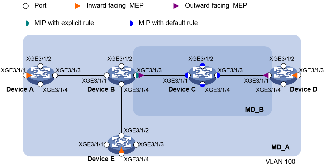
As shown in Figure 4:
· The network comprises five devices and is divided into two MDs: MD_A (level 5) and MD_B (level 3). All ports belong to VLAN 100, and the MAs in the two MDs all serve VLAN 100. Assume that the MAC addresses of Device A through Device E are 0010-FC01-6511, 0010-FC02-6512, 0010-FC03-6513, 0010-FC04-6514, and 0010-FC05-6515, respectively.
· MD_A has three edge ports: Ten-GigabitEthernet 3/1/1 on Device A, Ten-GigabitEthernet 3/1/3 on Device D, and Ten-GigabitEthernet 3/1/4 on Device E. They are all inward-facing MEPs. MD_B has two edge ports: Ten-GigabitEthernet 3/1/3 on Device B and Ten-GigabitEthernet 3/1/1 on Device D. They are both outward-facing MEPs.
· In MD_A, Device B is designed to have MIPs when its port is configured with low level MEPs. Port Ten-GigabitEthernet 3/1/3 is configured with MEPs of MD_B, and the MIPs of MD_A can be configured on this port. You must configure the MIP generation rule of MD_A as explicit.
· The MIPs of MD_B are designed on Device C, and are configured on all ports. You must configure the MIP generation rule as default.
· Configure CC to monitor the connectivity among all the MEPs in MD_A and MD_B. Configure LB to locate link faults, and use the AIS and EAIS functions to suppress the error alarms that are reported.
· After the status information of the entire network is obtained, use LT, LM, DM, and TST to detect link faults.
Procedure
1. Configure a VLAN and assign ports to it:
On each device shown in Figure 4, create VLAN 100 and assign ports Ten-GigabitEthernet 3/1/1 through Ten-GigabitEthernet 3/1/4 to VLAN 100.
2. Enable CFD:
# Enable CFD on Device A.
<DeviceA> system-view
[DeviceA] cfd enable
# Configure Device B through Device E in the same way Device A is configured. (Details not shown.)
3. Configure service instances:
# Create MD_A (level 5) on Device A, and create service instance 1 (in which the MA is identified by a VLAN and serves VLAN 100).
[DeviceA] cfd md MD_A level 5
[DeviceA] cfd service-instance 1 ma-id vlan-based md MD_A vlan 100
# Configure Device E in the same way Device A is configured. (Details not shown.)
# Create MD_A (level 5) on Device B, and create service instance 1 (in which the MA is identified by a VLAN and serves VLAN 100).
[DeviceB] cfd md MD_A level 5
[DeviceB] cfd service-instance 1 ma-id vlan-based md MD_A vlan 100
# Create MD_B (level 3), and create service instance 2 (in which the MA is identified by a VLAN and serves VLAN 100).
[DeviceB] cfd md MD_B level 3
[DeviceB] cfd service-instance 2 ma-id vlan-based md MD_B vlan 100
# Configure Device D in the same way Device B is configured. (Details not shown.)
# Create MD_B (level 3) on Device C, and create service instance 2 (in which the MA is identified by a VLAN and serves VLAN 100).
[DeviceC] cfd md MD_B level 3
[DeviceC] cfd service-instance 2 ma-id vlan-based md MD_B vlan 100
4. Configure MEPs:
# On Device A, configure a MEP list in service instance 1, and create inward-facing MEP 1001 in service instance 1 on Ten-GigabitEthernet 3/1/1.
[DeviceA] cfd meplist 1001 4002 5001 service-instance 1
[DeviceA] interface ten-gigabitethernet 3/1/1
[DeviceA-Ten-GigabitEthernet3/1/1] cfd mep 1001 service-instance 1 inbound
[DeviceA-Ten-GigabitEthernet3/1/1] quit
# On Device B, configure a MEP list in service instances 1 and 2.
[DeviceB] cfd meplist 1001 4002 5001 service-instance 1
[DeviceB] cfd meplist 2001 4001 service-instance 2
# Create outward-facing MEP 2001 in service instance 2 on Ten-GigabitEthernet 3/1/3.
[DeviceB] interface ten-gigabitethernet 3/1/3
[DeviceB-Ten-GigabitEthernet3/1/3] cfd mep 2001 service-instance 2 outbound
[DeviceB-Ten-GigabitEthernet3/1/3] quit
# On Device D, configure a MEP list in service instances 1 and 2.
[DeviceD] cfd meplist 1001 4002 5001 service-instance 1
[DeviceD] cfd meplist 2001 4001 service-instance 2
# Create outward-facing MEP 4001 in service instance 2 on Ten-GigabitEthernet 3/1/1.
[DeviceD] interface ten-gigabitethernet 3/1/1
[DeviceD-Ten-GigabitEthernet3/1/1] cfd mep 4001 service-instance 2 outbound
[DeviceD-Ten-GigabitEthernet3/1/1] quit
# Create inward-facing MEP 4002 in service instance 1 on Ten-GigabitEthernet 3/1/3.
[DeviceD] interface ten-gigabitethernet 3/1/3
[DeviceD-Ten-GigabitEthernet3/1/3] cfd mep 4002 service-instance 1 inbound
[DeviceD-Ten-GigabitEthernet3/1/3] quit
# On Device E, configure a MEP list in service instance 1.
[DeviceE] cfd meplist 1001 4002 5001 service-instance 1
# Create inward-facing MEP 5001 in service instance 1 on Ten-GigabitEthernet 3/1/4.
[DeviceE] interface ten-gigabitethernet 3/1/4
[DeviceE-Ten-GigabitEthernet3/1/4] cfd mep 5001 service-instance 1 inbound
[DeviceE-Ten-GigabitEthernet3/1/4] quit
5. Configure MIPs:
# Configure the MIP generation rule in service instance 1 on Device B as explicit.
[DeviceB] cfd mip-rule explicit service-instance 1
# Configure the MIP generation rule in service instance 2 on Device C as default.
[DeviceC] cfd mip-rule default service-instance 2
6. Configure CC:
# On Device A, enable the sending of CCM frames for MEP 1001 in service instance 1 on Ten-GigabitEthernet 3/1/1.
[DeviceA] interface ten-gigabitethernet 3/1/1
[DeviceA-Ten-GigabitEthernet3/1/1] cfd cc service-instance 1 mep 1001 enable
[DeviceA-Ten-GigabitEthernet3/1/1] quit
# On Device B, enable the sending of CCM frames for MEP 2001 in service instance 2 on Ten-GigabitEthernet 3/1/3.
[DeviceB] interface ten-gigabitethernet 3/1/3
[DeviceB-Ten-GigabitEthernet3/1/3] cfd cc service-instance 2 mep 2001 enable
[DeviceB-Ten-GigabitEthernet3/1/3] quit
# On Device D, enable the sending of CCM frames for MEP 4001 in service instance 2 on Ten-GigabitEthernet 3/1/1.
[DeviceD] interface ten-gigabitethernet 3/1/1
[DeviceD-Ten-GigabitEthernet3/1/1] cfd cc service-instance 2 mep 4001 enable
[DeviceD-Ten-GigabitEthernet3/1/1] quit
# Enable the sending of CCM frames for MEP 4002 in service instance 1 on Ten-GigabitEthernet 3/1/3.
[DeviceD] interface ten-gigabitethernet 3/1/3
[DeviceD-Ten-GigabitEthernet3/1/3] cfd cc service-instance 1 mep 4002 enable
[DeviceD-Ten-GigabitEthernet3/1/3] quit
# On Device E, enable the sending of CCM frames for MEP 5001 in service instance 1 on Ten-GigabitEthernet 3/1/4.
[DeviceE] interface ten-gigabitethernet 3/1/4
[DeviceE-Ten-GigabitEthernet3/1/4] cfd cc service-instance 1 mep 5001 enable
[DeviceE-Ten-GigabitEthernet3/1/4] quit
7. Configure hardware CC:
# Configure hardware CC on Ten-GigabitEthernet 3/1/1 of Device D to enable MEP 4001 to receive CCM frames from MEP 2001.
[DeviceD] interface ten-gigabitethernet 3/1/1
[DeviceD-Ten-GigabitEthernet3/1/1] cfd hardware-cc service-instance 2 remote-mep 2001
[DeviceD-Ten-GigabitEthernet3/1/1] quit
8. Configure AIS:
# Enable AIS on Device B. Configure the AIS frame transmission level as 5 and AIS frame transmission interval as 1 second in service instance 2.
[DeviceB] cfd ais enable
[DeviceB] cfd ais level 5 service-instance 2
[DeviceB] cfd ais period 1 service-instance 2
9. Configure EAIS:
# Enable port status-AIS collaboration on Device B.
[DeviceB] cfd ais-track link-status global
# On Ten-GigabitEthernet 3/1/3 of Device B, configure the EAIS frame transmission level as 5 and the EAIS frame transmission interval as 60 seconds. Specify the VLANs where the EAIS frames can be transmitted as VLAN 100.
[DeviceB] interface ten-gigabitethernet 3/1/3
[DeviceB-Ten-GigabitEthernet3/1/3] cfd ais-track link-status level 5
[DeviceB-Ten-GigabitEthernet3/1/3] cfd ais-track link-status period 60
[DeviceB-Ten-GigabitEthernet3/1/3] cfd ais-track link-status vlan 100
[DeviceB-Ten-GigabitEthernet3/1/3] quit
Verifying the configuration
1. Verify the LB function when the CC function detects a link fault:
# Enable LB on Device A to check the status of the link between MEP 1001 and MEP 5001 in service instance 1.
[DeviceA] cfd loopback service-instance 1 mep 1001 target-mep 5001
Loopback to MEP 5001 with the sequence number start from 1001-43404:
Reply from 0010-fc05-6515: sequence number=1001-43404 time=5ms
Reply from 0010-fc05-6515: sequence number=1001-43405 time=5ms
Reply from 0010-fc05-6515: sequence number=1001-43406 time=5ms
Reply from 0010-fc05-6515: sequence number=1001-43407 time=5ms
Reply from 0010-fc05-6515: sequence number=1001-43408 time=5ms
Sent: 5 Received: 5 Lost: 0
2. Verify the LT function after the CC function obtains the status information of the entire network:
# Identify the path between MEP 1001 and MEP 5001 in service instance 1 on Device A.
[DeviceA] cfd linktrace service-instance 1 mep 1001 target-mep 5001
Linktrace to MEP 5001 with the sequence number 1001-43462:
MAC address TTL Last MAC Relay action
0010-fc05-6515 63 0010-fc02-6512 Hit
3. Verify the one-way LM function after the CC function obtains the status information of the entire network:
# Use short-period LM to test the frame loss from MEP 1001 to MEP 4002 in service instance 1 on Device A.
[DeviceA] cfd slm service-instance 1 mep 1001 target-mep 4002
Reply from 0010-fc04-6514:
Far-end frame loss : 10 Far-end frame loss rate : 10.00%
Near-end frame loss: 20 Near-end frame loss rate: 20.00%
Reply from 0010-fc00-6514:
Far-end frame loss : 40 Far-end frame loss rate : 40.00%
Near-end frame loss: 40 Near-end frame loss rate: 40.00%
Reply from 0010-fc00-6514:
Far-end frame loss : 0 Far-end frame loss rate : 0.00%
Near-end frame loss: 10 Near-end frame loss rate: 10.00%
Reply from 0010-fc00-6514:
Far-end frame loss : 30 Far-end frame loss rate : 30.00%
Near-end frame loss: 30 Near-end frame loss rate: 30.00%
Average:
Far-end frame loss : 20 Far-end frame loss rate : 20.00%
Near-end frame loss: 25 Near-end frame loss rate: 25.00%
Packet statistics:
Sent LMMs: 5 Received: 5
# Use continual LM to test the frame loss from MEP 1001 to MEP 4002 in service instance 1 on Device A.
[DeviceA] cfd slm continual service-instance 1 mep 1001 target-mep 4002
# Display the one-way LM result on MEP 1001 in service instance 1 on Device A.
[DeviceA] display cfd slm history service-instance 1 mep 1001
Total continual tests: 1
Service instance: 1
MEP ID: 1001
Send status: Testing
Test state: Active
Reply from 0010-fc04-6514:
Far-end frame loss : 10 Far-end frame loss rate : 10.00%
Near-end frame loss: 20 Near-end frame loss rate: 20.00%
Reply from 0010-fc04-6514:
Far-end frame loss : 40 Far-end frame loss rate : 40.00%
Near-end frame loss: 40 Near-end frame loss rate: 40.00%
Reply from 0010-fc04-6514:
Far-end frame loss : 0 Far-end frame loss rate : 0.00%
Near-end frame loss: 10 Near-end frame loss rate: 10.00%
Reply from 0010-fc04-6514:
Far-end frame loss : 30 Far-end frame loss rate : 30.00%
Near-end frame loss: 30 Near-end frame loss rate: 30.00%
Reply from 0010-fc04-6514:
Far-end frame loss : 20 Far-end frame loss rate : 20.00%
Near-end frame loss: 25 Near-end frame loss rate: 25.00%
Average:
Far-end frame loss : 20 Far-end frame loss rate : 20.00%
Near-end frame loss: 25 Near-end frame loss rate: 25.00%
4. Verify the one-way DM function after the CC function obtains the status information of the entire network:
# Use short-period DM to test the one-way frame delay from MEP 1001 to MEP 4002 in service instance 1 on Device A.
[DeviceA] cfd dm one-way service-instance 1 mep 1001 target-mep 4002
5 1DMs have been sent. Please check the result on the remote device.
# Display the one-way DM result on MEP 4002 in service instance 1 on Device D.
[DeviceD] display cfd dm one-way history service-instance 1 mep 4002
Total continual tests: 1
Service instance: 1
MEP ID: 4002
Send status: Testing
Test state: Active
Frame delay: 10ms 9ms 11ms 5ms 5ms
Delay average: 8ms
Frame jitter: 1ms 2ms 6ms 0ms
Variation average: 2ms
# Use continual DM to test the frame loss from MEP 1001 to MEP 4002 in service instance 1 on Device A.
[DeviceA] cfd dm one-way continual service-instance 1 mep 1001 target-mep 4002
# Display the one-way DM result on MEP 4002 in service instance 1 on Device D.
[DeviceD] display cfd dm one-way history service-instance 1 mep 4002
Service instance: 1
MEP ID: 4002
Sent 1DM total number: 0
Received 1DM total number: 5
Frame delay: 10ms 9ms 11ms 5ms 5ms
Delay average: 8ms
Frame jitter: 1ms 2ms 6ms 0ms
Variation average: 2ms
5. Verify the two-way DM function after the CC function obtains the status information of the entire network:
# Use short-period DM to test the two-way frame delay from MEP 1001 to MEP 4002 in service instance 1 on Device A.
[DeviceA] cfd dm two-way service-instance 1 mep 1001 target-mep 4002
Frame delay:
Reply from 0010-fc00-6514: 10us
Reply from 0010-fc00-6514: 9us
Reply from 0010-fc00-6514: 11us
Reply from 0010-fc00-6514: 5us
Reply from 0010-fc00-6514: 5us
Average: 8us
Frame jitter: 1us 2us 6us 0us
Average: 2us
Packet statistics:
Sent DMMs: 5 Received: 5 Lost: 0
# Use continual DM to test the two-way frame delay from MEP 1001 to MEP 4002 in service instance 1 on Device A.
[DeviceA] cfd dm two-way continual service-instance 1 mep 1001 target-mep 4002
# Display the two-way DM result on MEP 1001 in service instance 1 on Device A.
[DeviceA] display cfd dm two-way history service-instance 1 mep 1001
Total continual tests: 1
Service instance: 1
MEP ID: 1001
Send status: Testing
Test state: Active
Frame delay:
Reply from 0010-fc00-6514: 10us
Reply from 0010-fc00-6514: 9us
Reply from 0010-fc00-6514: 11us
Reply from 0010-fc00-6514: 5us
Reply from 0010-fc00-6514: 5us
Average: 8us
Frame jitter: 1us 2us 6us 0us
Average: 2us
6. Verify the TST function after the CC function obtains the status information of the entire network:
# Use short-period TST to test the bit errors on the link from MEP 1001 to MEP 4002 in service instance 1 on Device A.
[DeviceA] cfd tst service-instance 1 mep 1001 target-mep 4002
5 TSTs have been sent. Please check the result on the remote device.
# Display the short-period TST result on MEP 4002 in service instance 1 on Device D.
[DeviceD] display cfd tst history service-instance 1 mep 4002
Service instance: 1
MEP ID: 4002
Send status: Testing
Test state: Active
Received from 0010-fc01-6511, Bit True, sequence number 0
Received from 0010-fc01-6511, Bit True, sequence number 1
Received from 0010-fc01-6511, Bit True, sequence number 2
Received from 0010-fc01-6511, Bit True, sequence number 3
Received from 0010-fc01-6511, Bit True, sequence number 4
Sent TST total number: 7
Received TST total number: 5
Received bit error TST number: 0
Percentage of error messages: 0.00%
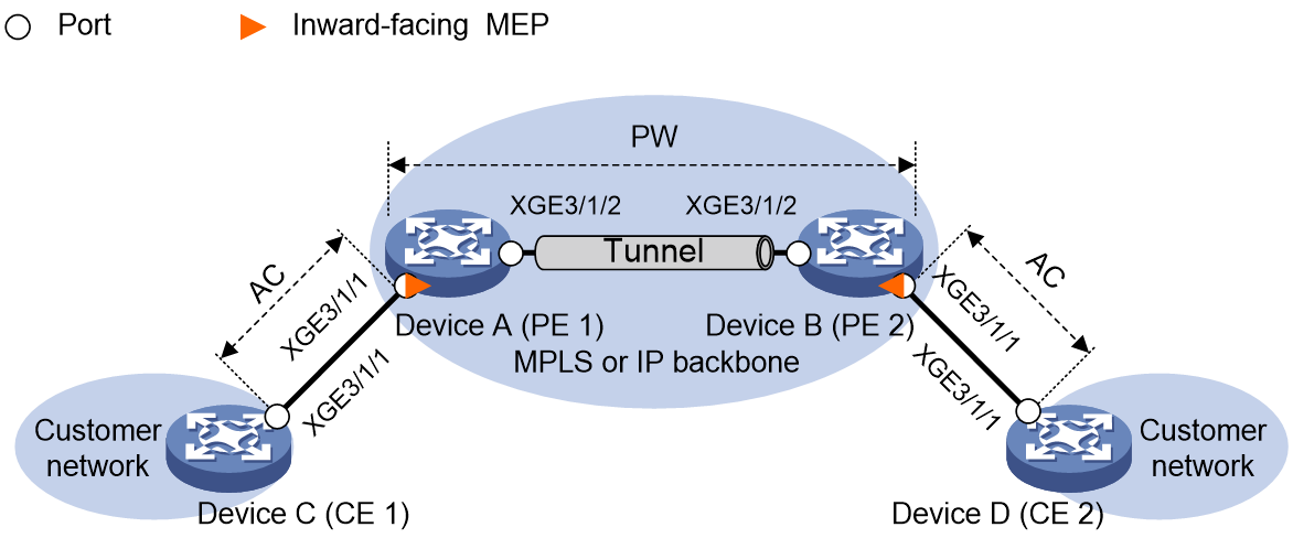
Example: Configuring CFD in a Layer 2 VPN (L2VPN networking)
Network configuration
As shown in Figure 5:
· Configure a static PW between PE 1 and PE 2 to enable CE 1 and CE 2 to communicate with each other. Assume that the MAC addresses of Device A through Device D are 0010-FC01-6511, 0010-FC02-6512, 0010-FC03-6513, and 0010-FC04-6514, respectively.
· Configure Ten-GigabitEthernet 3/1/1.1 on Device A and Device B as AC interfaces, and associate them with cross-connect svc of cross-connect group vpna.
· Assign the network to MD_A (level 5). MD_A has two edge interfaces: Ten-GigabitEthernet 3/1/1.1 on Device A and Ten-GigabitEthernet 3/1/1.1 on Device B. They are both inward-facing MEPs.
· Configure CC to monitor the connectivity between the inward-facing MEPs. Configure LB to locate link faults.
· After the status information of the entire network is obtained, use LT, LM, and DM to detect link faults.
Procedure
1. Configure a static PW. (Details not shown.)
For information about configuring a static PW, see MPLS L2VPN in MPLS Configuration Guide.
2. Enable CFD:
# Enable CFD on Device A.
<DeviceA> system-view
[DeviceA] cfd enable
# Configure Device B in the same way Device A is configured. (Details not shown.)
3. Configure service instances:
# Create MD_A (level 5) on Device A, and create service instance 1 (in which the MA is identified by vpnma and serves cross-connect svc of cross-connect group vpna).
[DeviceA] cfd md MD_A level 5
[DeviceA] cfd service-instance 1 ma-id string vpnma md MD_A xconnect-group vpna connection svc
# Configure Device B in the same way Device A is configured. (Details not shown.)
4. Configure MEPs:
# On Device A, configure a MEP list in service instance 1, and create inward-facing MEP 1001 in service instance 1 on Ten-GigabitEthernet 3/1/1.1.
[DeviceA] cfd meplist 1001 2001 service-instance 1
[DeviceA] interface ten-gigabitethernet 3/1/1.1
[DeviceA-Ten-GigabitEthernet3/1/1.1] cfd mep 1001 service-instance 1 inbound
[DeviceA-Ten-GigabitEthernet3/1/1.1] quit
# On Device B, configure a MEP list in service instance 1, and create inward-facing MEP 2001 in service instance 1 on Ten-GigabitEthernet 3/1/1.1.
[DeviceB] cfd meplist 1001 2001 service-instance 1
[DeviceB] interface ten-gigabitethernet 3/1/1.1
[DeviceB-Ten-GigabitEthernet3/1/1.1] cfd mep 2001 service-instance 1 inbound
[DeviceB-Ten-GigabitEthernet3/1/1.1] quit
5. Configure CC:
# On Device A, enable the sending of CCM frames for MEP 1001 in service instance 1 on Ten-GigabitEthernet 3/1/1.1.
[DeviceA] interface ten-gigabitethernet 3/1/1.1
[DeviceA-Ten-GigabitEthernet3/1/1.1] cfd cc service-instance 1 mep 1001 enable
[DeviceA-Ten-GigabitEthernet3/1/1.1] quit
# On Device B, enable the sending of CCM frames for MEP 2001 in service instance 1 on Ten-GigabitEthernet 3/1/1.1.
[DeviceB] interface ten-gigabitethernet 3/1/1.1
[DeviceB-Ten-GigabitEthernet3/1/1.1] cfd cc service-instance 1 mep 2001 enable
[DeviceB-Ten-GigabitEthernet3/1/1.1] quit
6. Configure the frame counting mode:
# Configure the frame counting mode as port-based for Ten-GigabitEthernet 3/1/1.1 on Device A.
[DeviceA] interface ten-gigabitethernet 3/1/1.1
[DeviceA-Ten-GigabitEthernet3/1/1.1] cfd frame-count mode port-based
[DeviceA-Ten-GigabitEthernet3/1/1.1] quit
# Configure the frame counting mode as port-based for Ten-GigabitEthernet 3/1/1.1 on Device B.
[DeviceB] interface ten-gigabitethernet 3/1/1.1
[DeviceB-Ten-GigabitEthernet3/1/1.1] cfd frame-count mode port-based
[DeviceB-Ten-GigabitEthernet3/1/1.1] quit
Verifying the configuration
1. Verify the LB function when the CC function detects a link fault:
# Enable LB on Device A to check the status of the link between MEP 1001 and MEP 2001 in service instance 1.
[DeviceA] cfd loopback service-instance 1 mep 1001 target-mep 2001
Loopback to MEP 2001 with the sequence number start from 1001-43404:
Reply from 0010-fc02-6512: sequence number=1001-43404 time=5ms
Reply from 0010-fc02-6512: sequence number=1001-43405 time=5ms
Reply from 0010-fc02-6512: sequence number=1001-43406 time=5ms
Reply from 0010-fc02-6512: sequence number=1001-43407 time=5ms
Reply from 0010-fc02-6512: sequence number=1001-43408 time=5ms
Sent: 5 Received: 5 Lost: 0
2. Verify the LT function after the CC function obtains the status information of the entire network:
# Identify the path between MEP 1001 and MEP 2001 in service instance 1 on Device A.
[DeviceA] cfd linktrace service-instance 1 mep 1001 target-mep 2001
Linktrace to MEP 2001 with the sequence number 1001-43462:
MAC address TTL Last MAC Relay action
0010-fc02-6512 63 0010-fc02-6512 Hit
3. Verify the one-way LM function after the CC function obtains the status information of the entire network:
# Use short-period LM to test the frame loss from MEP 1001 to MEP 2001 in service instance 1 on Device A.
[DeviceA] cfd slm service-instance 1 mep 1001 target-mep 2001
Reply from 0010-fc02-6512:
Far-end frame loss : 10 Far-end frame loss rate : 10.00%
Near-end frame loss: 20 Near-end frame loss rate: 20.00%
Reply from 0010-fc02-6512:
Far-end frame loss : 40 Far-end frame loss rate : 40.00%
Near-end frame loss: 40 Near-end frame loss rate: 40.00%
Reply from 0010-fc02-6512:
Far-end frame loss : 0 Far-end frame loss rate : 0.00%
Near-end frame loss: 10 Near-end frame loss rate: 10.00%
Reply from 0010-fc02-6512:
Far-end frame loss : 30 Far-end frame loss rate : 30.00%
Near-end frame loss: 30 Near-end frame loss rate: 30.00%
Average:
Far-end frame loss : 20 Far-end frame loss rate : 20.00%
Near-end frame loss: 25 Near-end frame loss rate: 25.00%
Packet statistics:
Sent LMMs: 5 Received: 5
# Use continual LM to test the frame delay from MEP 1001 to MEP 2001 in service instance 1 on Device A.
[DeviceA] cfd slm continual service-instance 1 mep 1001 target-mep 2001
# Display the one-way LM result on MEP 1001 in service instance 1 on Device A.
[DeviceA] display cfd slm history service-instance 1 mep 1001
Total continual tests: 1
Service instance: 1
MEP ID: 1001
Send status: Testing
Test state: Active
Reply from 0010-fc02-6512:
Far-end frame loss : 10 Far-end frame loss rate : 10.00%
Near-end frame loss: 20 Near-end frame loss rate: 20.00%
Reply from 0010-fc02-6512:
Far-end frame loss : 40 Far-end frame loss rate : 40.00%
Near-end frame loss: 40 Near-end frame loss rate: 40.00%
Reply from 0010-fc02-6512:
Far-end frame loss : 0 Far-end frame loss rate : 0.00%
Near-end frame loss: 10 Near-end frame loss rate: 10.00%
Reply from 0010-fc02-6512:
Far-end frame loss : 30 Far-end frame loss rate : 30.00%
Near-end frame loss: 30 Near-end frame loss rate: 30.00%
Reply from 0010-fc02-6512:
Far-end frame loss : 20 Far-end frame loss rate : 20.00%
Near-end frame loss: 25 Near-end frame loss rate: 25.00%
Average:
Far-end frame loss : 20 Far-end frame loss rate : 20.00%
Near-end frame loss: 25 Near-end frame loss rate: 25.00%
4. Verify the two-way LM function after the CC function obtains the status information of the entire network:
# Use short-period LM to test the frame loss from MEP 1001 to MEP 2001 in service instance 1 on Device A.
[DeviceA] cfd dlm continual service-instance 1 mep 1001 target-mep 2001
# Use continual LM to test the frame loss from MEP 2001 to MEP 1001 in service instance 1 on Device B.
[DeviceB] cfd dlm continual service-instance 1 mep 2001 target-mep 1001
# Display the two-way LM result on MEP 1001 in service instance 1 on Device A.
[DeviceA] display cfd dlm history service-instance 1 mep 1001
Total continual tests: 1
Service instance: 1
MEP ID: 1001
Send status: Testing
Test state: Active
Reply from 0010-fc02-6512:
Far-end frame loss : 10 Far-end frame loss rate : 10.00%
Near-end frame loss: 20 Near-end frame loss rate: 20.00%
Reply from 0010-fc02-6512:
Far-end frame loss : 40 Far-end frame loss rate : 40.00%
Near-end frame loss: 40 Near-end frame loss rate: 40.00%
Reply from 0010-fc02-6512:
Far-end frame loss : 0 Far-end frame loss rate : 0.00%
Near-end frame loss: 10 Near-end frame loss rate: 10.00%
Reply from 0010-fc02-6512:
Far-end frame loss : 30 Far-end frame loss rate : 30.00%
Near-end frame loss: 30 Near-end frame loss rate: 30.00%
Reply from 0010-fc02-6512:
Far-end frame loss : 20 Far-end frame loss rate : 20.00%
Near-end frame loss: 25 Near-end frame loss rate: 25.00%
Average:
Far-end frame loss : 20 Far-end frame loss rate : 20.00%
Near-end frame loss: 25 Near-end frame loss rate: 25.00%
5. Verify the one-way DM function after the CC function obtains the status information of the entire network:
# Use short-period DM to test the frame delay from MEP 1001 to MEP 2001 in service instance 1 on Device A.
[DeviceA] cfd dm one-way service-instance 1 mep 1001 target-mep 2001
5 1DMs have been sent. Please check the result on the remote device.
# Display the one-way DM result on MEP 1001 in service instance 1 on Device B.
[DeviceB] display cfd dm one-way history service-instance 1 mep 2001
Service instance: 1
MEP ID: 2001
Sent 1DM total number: 0
Received 1DM total number: 5
Frame delay: 10us 9us 11us 5us 5us
Delay average: 8us
Frame jitter: 1us 2us 6us 0us
Variation average: 2us
# Use continual DM to test the frame delay from MEP 1001 to MEP 2001 in service instance 1 on Device A.
[DeviceA] cfd dm one-way continual service-instance 1 mep 1001 target-mep 2001
# Display the one-way DM result on MEP 1001 in service instance 1 on Device B.
[DeviceB] display cfd dm one-way history service-instance 1 mep 2001
Total continual tests: 1
Service instance: 1
MEP ID: 2001
Send status: Testing
Test state: Active
Frame delay: 10us 9us 11us 5us 5us
Delay average: 8us
Frame jitter: 1us 2us 6us 0us
Variation average: 2us
6. Verify the two-way DM function after the CC function obtains the status information of the entire network:
# Use short-period DM to test the two-way frame delay from MEP 1001 to MEP 2001 in service instance 1 on Device A.
[DeviceA] cfd dm two-way service-instance 1 mep 1001 target-mep 2001
Frame delay:
Reply from 0010-fc02-6512: 10us
Reply from 0010-fc02-6512: 9us
Reply from 0010-fc02-6512: 11us
Reply from 0010-fc02-6512: 5us
Reply from 0010-fc02-6512: 5us
Average: 8us
Frame jitter: 1us 2us 6us 0us
Average: 2us
Packet statistics:
Sent DMMs: 5 Received: 5 Lost: 0
# Use continual DM to test the frame delay from MEP 1001 to MEP 2001 in service instance 1 on Device A.
[DeviceA] cfd dm one-way continual service-instance 1 mep 1001 target-mep 2001
# Display the two-way DM result on MEP 1001 in service instance 1 on Device A.
[DeviceA] display cfd dm two-way history service-instance 1 mep 1001
Total continual tests: 1
Service instance: 1
MEP ID: 1001
Send status: Testing
Test state: Active
Frame delay:
Reply from 0010-fc02-6512: 10us
Reply from 0010-fc02-6512: 9us
Reply from 0010-fc02-6512: 11us
Reply from 0010-fc02-6512: 5us
Reply from 0010-fc02-6512: 5us
Average: 8us
Frame jitter: 1us 2us 6us 0us
Average: 2us
Network configuration
As shown in Figure 6:
· Configure a static PW between PE 1 and PE 2 to enable CE 1 and CE 2 to communicate in VLAN 10. Assume that the MAC addresses of Device A through Device D are 0010-FC01-6511, 0010-FC02-6512, 0010-FC03-6513, and 0010-FC04-6514, respectively.
· Create Ethernet service instance 10 on Ten-GigabitEthernet 3/1/1 of PE 1 and PE 2 to match incoming packets with VLAN ID 10 on Ten-GigabitEthernet 3/1/1. Configure Ten-GigabitEthernet 3/1/1 on Device A and Device B as AC interfaces, and associate them with cross-connect svc of cross-connect group vpna.
· Assign the network to MD_A (level 5). MD_A has two edge interfaces: Ten-GigabitEthernet 3/1/1 on Device A and Ten-GigabitEthernet 3/1/1 on Device B. They are both inward-facing MEPs.
· Configure CC to monitor the connectivity between the inward-facing MEPs. Configure LB to locate link faults.
· After the status information of the entire network is obtained, use LT, LM, and DM to detect link faults.
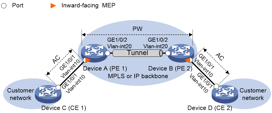
Procedure
1. Configure VLANs and assign interfaces to them:
On each device shown in Figure 6, create VLAN 10 and VLAN 20, assign Ten-GigabitEthernet 3/1/1 to VLAN 10, and assign Ten-GigabitEthernet 3/1/2 to VLAN 20.
2. Configure a static PW. (Details not shown.)
For information about configuring a static PW, see MPLS L2VPN in MPLS Configuration Guide.
3. Enable CFD:
# Enable CFD on Device A.
<DeviceA> system-view
[DeviceA] cfd enable
# Configure Device B in the same way Device A is configured. (Details not shown.)
4. Configure service instances:
# Create MD_A (level 5) on Device A, and create service instance 1 (in which the MA is identified by vpnma and serves cross-connect svc of cross-connect group vpna).
[DeviceA] cfd md MD_A level 5
[DeviceA] cfd service-instance 1 ma-id string vpnma md MD_A xconnect-group vpna connection svc
# Configure Device B in the same way Device A is configured. (Details not shown.)
5. Configure MEPs:
# On Device A, configure a MEP list in service instance 1, and create inward-facing MEP 1001 in Ethernet service instance 10 on Ten-GigabitEthernet 3/1/1.
[DeviceA] cfd meplist 1001 2001 service-instance 1
[DeviceA] interface ten-gigabitethernet 3/1/1
[DeviceA-Ten-GigabitEthernet3/1/1] service-instance 10
[DeviceA-Ten-GigabitEthernet3/1/1-srv10] cfd mep 1001 service-instance 1 inbound
[DeviceA-Ten-GigabitEthernet3/1/1-srv10] quit
# On Device B, configure a MEP list in service instance 1, and create inward-facing MEP 2001 in Ethernet service instance 10 on Ten-GigabitEthernet 3/1/1.
[DeviceB] cfd meplist 1001 2001 service-instance 1
[DeviceB] interface ten-gigabitethernet 3/1/1
[DeviceB-Ten-GigabitEthernet3/1/1] service-instance 10
[DeviceB-Ten-GigabitEthernet3/1/1-srv10] cfd mep 2001 service-instance 1 inbound
[DeviceB-Ten-GigabitEthernet3/1/1-srv10] quit
6. Configure CC:
# On Device A, enable the sending of CCM frames for MEP 1001 in Ethernet service instance 10 on Ten-GigabitEthernet 3/1/1.
[DeviceA] interface ten-gigabitethernet 3/1/1
[DeviceA-Ten-GigabitEthernet3/1/1] service-instance 10
[DeviceA-Ten-GigabitEthernet3/1/1-srv10] cfd cc service-instance 1 mep 1001 enable
[DeviceA-Ten-GigabitEthernet3/1/1-srv10] quit
# On Device B, enable the sending of CCM frames for MEP 2001 in Ethernet service instance 10 on Ten-GigabitEthernet 3/1/1.
[DeviceB] interface ten-gigabitethernet 3/1/1
[DeviceB-Ten-GigabitEthernet3/1/1] service-instance 10
[DeviceB-Ten-GigabitEthernet3/1/1-srv10] cfd cc service-instance 1 mep 2001 enable
[DeviceB-Ten-GigabitEthernet3/1/1-srv10] quit
7. Configure the frame counting mode:
# Configure the frame counting mode as port-based for Layer 2 Ethernet service instance on Ten-GigabitEthernet 3/1/1 on Device A.
[DeviceA] interface ten-gigabitethernet 3/1/1
[DeviceA-Ten-GigabitEthernet3/1/1] service-instance 10
[DeviceA-Ten-GigabitEthernet3/1/1-srv10] cfd frame-count mode port-based
[DeviceA-Ten-GigabitEthernet3/1/1-srv10] quit
# Configure the frame counting mode as port-based for Layer 2 Ethernet service instance on Ten-GigabitEthernet 3/1/1 on Device B.
[DeviceB] interface ten-gigabitethernet 3/1/1
[DeviceB-Ten-GigabitEthernet3/1/1] service-instance 10
[DeviceB-Ten-GigabitEthernet3/1/1-srv10] cfd frame-count mode port-based
[DeviceB-Ten-GigabitEthernet3/1/1-srv10] quit
Verifying the configuration
1. Verify the LB function when the CC function detects a link fault:
# Enable LB on Device A to check the status of the link between MEP 1001 and MEP 2001 in service instance 1.
[DeviceA] cfd loopback service-instance 1 mep 1001 target-mep 2001
Loopback to MEP 2001 with the sequence number start from 1001-43404:
Reply from 0010-fc02-6512: sequence number=1001-43404 time=5ms
Reply from 0010-fc02-6512: sequence number=1001-43405 time=5ms
Reply from 0010-fc02-6512: sequence number=1001-43406 time=5ms
Reply from 0010-fc02-6512: sequence number=1001-43407 time=5ms
Reply from 0010-fc02-6512: sequence number=1001-43408 time=5ms
Sent: 5 Received: 5 Lost: 0
2. Verify the LT function after the CC function obtains the status information of the entire network:
# Identify the path between MEP 1001 and MEP 2001 in service instance 1 on Device A.
[DeviceA] cfd linktrace service-instance 1 mep 1001 target-mep 2001
Linktrace to MEP 2001 with the sequence number 1001-43462:
MAC address TTL Last MAC Relay action
0010-fc02-6512 63 0010-fc02-6512 Hit
3. Verify the one-way LM function after the CC function obtains the status information of the entire network:
# Use short-period LM to test the frame loss from MEP 1001 to MEP 2001 in service instance 1 on Device A.
[DeviceA] cfd slm service-instance 1 mep 1001 target-mep 2001
Reply from 0010-fc02-6512:
Far-end frame loss : 10 Far-end frame loss rate : 10.00%
Near-end frame loss: 20 Near-end frame loss rate: 20.00%
Reply from 0010-fc02-6512:
Far-end frame loss : 40 Far-end frame loss rate : 40.00%
Near-end frame loss: 40 Near-end frame loss rate: 40.00%
Reply from 0010-fc02-6512:
Far-end frame loss : 0 Far-end frame loss rate : 0.00%
Near-end frame loss: 10 Near-end frame loss rate: 10.00%
Reply from 0010-fc02-6512:
Far-end frame loss : 30 Far-end frame loss rate : 30.00%
Near-end frame loss: 30 Near-end frame loss rate: 30.00%
Reply from 0010-fc02-6512:
Far-end frame loss : 20 Far-end frame loss rate : 20.00%
Near-end frame loss: 25 Near-end frame loss rate: 25.00%
Average:
Far-end frame loss : 20 Far-end frame loss rate : 20.00%
Near-end frame loss: 25 Near-end frame loss rate: 25.00%
Packet statistics:
Sent LMMs: 5 Received: 5
# Use continual LM to test the frame delay from MEP 1001 to MEP 2001 in service instance 1 on Device A.
[DeviceA] cfd slm continual service-instance 1 mep 1001 target-mep 2001
# Display the one-way LM result on MEP 1001 in service instance 1 on Device A.
[DeviceA] display cfd slm history service-instance 1 mep 1001
Total continual tests: 1
Service instance: 1
MEP ID: 1001
Send status: Testing
Test state: Active
Reply from 0010-fc02-6512:
Far-end frame loss : 10 Far-end frame loss rate : 10.00%
Near-end frame loss: 20 Near-end frame loss rate: 20.00%
Reply from 0010-fc02-6512:
Far-end frame loss : 40 Far-end frame loss rate : 40.00%
Near-end frame loss: 40 Near-end frame loss rate: 40.00%
Reply from 0010-fc02-6512:
Far-end frame loss : 0 Far-end frame loss rate : 0.00%
Near-end frame loss: 10 Near-end frame loss rate: 10.00%
Reply from 0010-fc02-6512:
Far-end frame loss : 30 Far-end frame loss rate : 30.00%
Near-end frame loss: 30 Near-end frame loss rate: 30.00%
Reply from 0010-fc02-6512:
Far-end frame loss : 20 Far-end frame loss rate : 20.00%
Near-end frame loss: 25 Near-end frame loss rate: 25.00%
Average:
Far-end frame loss : 20 Far-end frame loss rate : 20.00%
Near-end frame loss: 25 Near-end frame loss rate: 25.00%
4. Verify the one-way DM function after the CC function obtains the status information of the entire network:
# Use short-period DM to test the frame delay from MEP 1001 to MEP 2001 in service instance 1 on Device A.
[DeviceA] cfd dm one-way service-instance 1 mep 1001 target-mep 2001
5 1DMs have been sent. Please check the result on the remote device.
# Display the one-way DM result on MEP 2001 in service instance 1 on Device B.
[DeviceB] display cfd dm one-way history service-instance 1 mep 2001
Service instance: 1
MEP ID: 2001
Sent 1DM total number: 0
Received 1DM total number: 5
Frame delay: 10us 9us 11us 5us 5us
Delay average: 8us
Frame jitter: 1us 2us 6us 0us
Variation average: 2us
# Use continual DM to test the frame delay from MEP 1001 to MEP 2001 in service instance 1 on Device A.
[DeviceA] cfd dm one-way continual service-instance 1 mep 1001 target-mep 2001
# Display the one-way DM result on MEP 2001 in service instance 1 on Device B.
[DeviceB] display cfd dm one-way history service-instance 1 mep 2001
Total continual tests: 1
Service instance: 1
MEP ID: 2001
Send status: Testing
Test state: Active
Frame delay: 10us 9us 11us 5us 5us
Delay average: 8us
Frame jitter: 1us 2us 6us 0us
Variation average: 2us
5. Verify the two-way DM function after the CC function obtains the status information of the entire network:
# Use short-period DM to test the two-way frame delay from MEP 1001 to MEP 2001 in service instance 1 on Device A.
[DeviceA] cfd dm two-way service-instance 1 mep 1001 target-mep 2001
Frame delay:
Reply from 0010-fc02-6512: 10us
Reply from 0010-fc02-6512: 9us
Reply from 0010-fc02-6512: 11us
Reply from 0010-fc02-6512: 5us
Reply from 0010-fc02-6512: 5us
Average: 8us
Frame jitter: 1us 2us 6us 0us
Average: 2us
Packet statistics:
Sent DMMs: 5 Received: 5 Lost: 0
# Use continual DM to test the frame delay from MEP 1001 to MEP 2001 in service instance 1 on Device A.
[DeviceA] cfd dm one-way continual service-instance 1 mep 1001 target-mep 2001
# Display the two-way DM result on MEP 1001 in service instance 1 on Device A.
[DeviceA] display cfd dm two-way history service-instance 1 mep 1001
Total continual tests: 1
Service instance: 1
MEP ID: 1001
Send status: Testing
Test state: Active
Frame delay:
Reply from 0010-fc02-6512: 10us
Reply from 0010-fc02-6512: 9us
Reply from 0010-fc02-6512: 11us
Reply from 0010-fc02-6512: 5us
Reply from 0010-fc02-6512: 5us
Average: 8us
Frame jitter: 1us 2us 6us 0us
Average: 2us
