- Table of Contents
-
- 14-High Availability Configuration Guide
- 00-Preface
- 01-Ethernet OAM configuration
- 02-CFD configuration
- 03-DLDP configuration
- 04-Monitor Link configuration
- 05-S-Trunk configuration
- 06-Error code detection configuration
- 07-VRRP configuration
- 08-VSRP configuration
- 09-Failover group configuration
- 10-Service instance group configuration
- 11-BFD configuration
- 12-Track configuration
- 13-Process placement configuration
- Related Documents
-
| Title | Size | Download |
|---|---|---|
| 06-Error code detection configuration | 132.07 KB |
Contents
Configuring error code detection
Error code detection fundamentals
Interface error code detection
Error code detection deployment
Restrictions and guidelines: Error code detection configuration
Configuring interface error code detection
Configuring link quality detection
Configuring the bit error ratio calculation factors for an interface
Specifying the protocol for transferring error code detection information
Display and maintenance commands for error code detection
Configuring error code detection
About error code detection
As an high availability mechanism, error code detection triggers the upper-layer service module to automatically take protection actions when error code events occur. This feature reduces the influence of error codes on the service.
Error code detection fundamentals
Interface error code detection
With this feature configured on an interface, the device periodically samples, calculates, and detects the packets received on the interface.
· If the bit error ratio exceeds the upper threshold, an error code failure occurs on the interface. Then, an error code event is reported to trigger the upper-layer service module to take the corresponding protection action.
· If the bit error ratio drops below the lower threshold, the error code failure is cleared on the interface. Then, an error code clearing event is reported to trigger the upper-layer service module to cancel the protection action.
Interface error code detection supports the following protection actions:
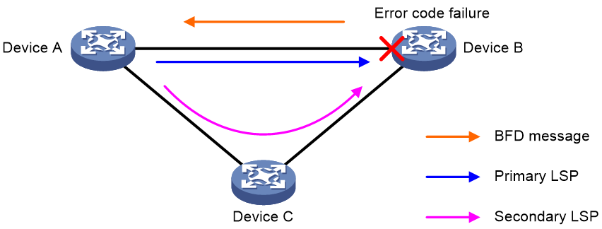
· Trigger LSP—Error code failures on an interface can trigger LSP switchover. An error code failure occurring on an interface is reported to the upper-layer service module to switch traffic from the primary LSP to the secondary LSP. After the error code failure is cleared, traffic is switched back to the primary LSP.
As shown in Figure 1, each interface has error code detection enabled for triggering LSP switchover. LDP labels are distributed among nodes. Typically, MPLS traffic is forwarded over the primary LSP. When error codes are detected on Device B, the following events occur:
¡ Device B senses the primary LSP failure, and switches traffic to the secondary LSP. At the same, Device B sends BFD messages to notify Device A of the error code failure.
¡ After Device A receives BFD messages from Device B, Device A also senses the primary LSP failure, and switches traffic to the secondary LSP.
Figure 1 Schematic diagram for error code detection for triggering LSP switchover
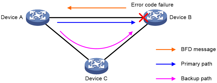
· Trigger Section—Error code failures on an interface can trigger section layer service protection. An error code failure occurring on an interface is reported to the interface management module to set the link layer protocol status of the interface to DOWN(Bit-error down). Then, the upper-layer service module associated with the interface triggers section layer service protection. After the error code failure is cleared, the link layer protocol status of the interface restores to UP and triggers the upper-layer service module to cancel section layer service protection.
As shown in Figure 2, each interface has error code detection enabled for triggering section layer service protection. All nodes can reach each other through IS-IS routes. Normally, both Device A and Device B preferentially use the primary path for IS-IS routes. Therefore, traffic in each direction is forwarded by the primary path. When error codes are detected on Device B, the following events occur:
¡ The link layer protocol state of the corresponding interface on Device B becomes DOWN(Bit-error down) to trigger switching the IS-IS route to the backup path, so the traffic from Device B to Device A is forwarded through the backup path. At the same time, Device B sends BFD messages to notify Device A of the error code failure.
¡ After Device A receives the BFD messages from Device B, the link layer protocol state of the corresponding interface on Device A becomes DOWN(Bit-error down) to trigger switching the IS-IS route to the backup path, so the traffic from Device A to Device B is forwarded through the backup path.
Figure 2 Schematic diagram for error code detection for triggering section layer service protection
Link quality detection
With this feature configured on an interface, the device periodically samples, calculates, and detects the packets received on the interface.
· If the bit error ratio exceeds the upper threshold, an error code failure occurs on the interface. Then, the link quality of the interface becomes LOW, and an error code event is reported. In this case, IGP (for example, OSPF and IS-IS) increases the cost for the link and recalculates the routes, so that IGP does not preferentially select the link and keeps off error code failures.
· If the bit error ratio drops below the lower threshold, the error code failure is cleared on the interface. Then, the link quality of the interface restores to GOOD, and an error code clearing event is reported. In this case, IGP restores the cost value for the interface and recalculates the routes, so that IGP can preferentially select the link again.
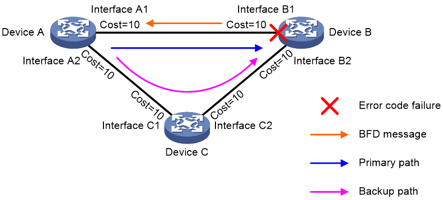
As shown in Figure 3, each interface has link quality detection enabled. All nodes can reach each other through IS-IS routes. Normally, both Device A and Device B preferentially use the primary path for IS-IS routes. Therefore, traffic in each direction is forwarded by the primary path. When error codes are detected on interface B1 of Device B, the following events occur:
· Device B sets the link quality level to LOW for interface B1 to trigger IS-IS to increase the cost for the link (for example, 40). At the same time, Device B sends BFD messages to notify Device A of the error code failure.
· After Device A receives BFD messages from Device B, Device A also sets the link quality level to LOW for interface A1 to trigger IS-IS to increase the cost for the link (for example, 40).
In this case, the cost of the backup path (20) is smaller than the cost of the primary path (40). As a result, the IS-IS routes on both Device A and Device B preferentially select the backup path, and bidirectional traffic between Device A and Device B is switched to the backup path to bypass error code failures.
Figure 3 Schematic diagram for link quality detection
When an error code failure occurs on a Layer 3 Ethernet interface that is not assigned to any aggregation group, LSP switchover is also triggered in addition to link cost adjustment and IGP route recalculation.
Background traffic
To guarantee the error code detection accuracy on an interface, make sure the interface has enough traffic. For error code detection to take effect on an interface with no or little service traffic, sending a type of specific traffic must be automatically started or stopped according to the service traffic size on the interface. In this way, the error code failures can be accurately located on the interface. This type of traffic is called background traffic.
After an error code failure occurs on an interface, the error code failure on the interface cannot be automatically recovered if no service traffic exists on the interface. To solve this problem, the device will automatically enable the background traffic sending function when error code detection is configured on an interface. The background traffic contains 64-byte all-0 packets with the lowest priority. Therefore, the background traffic can provide enough samples for error code detection without affecting services, so that the error code failure can be fast recovered
Background traffic sending is automatically started or stopped according to the service traffic size as follows:
· When the interface speed is greater than or equal to 1000 Mbps and the outgoing traffic rate is smaller than 100 Mbps, background traffic sending automatically starts. The interface will automatically send background traffic at 300 Mbps.
· When the outgoing traffic rate of an interface exceeds 300 Mbps, the interface will automatically stop sending background traffic.
Error code detection deployment
In the current software version, you can deploy error code detection only on Ethernet interfaces and aggregate interfaces.
· With this feature configured on an Ethernet interface, this feature samples, calculates, and detects the bit error ratio of the Ethernet interface, and the bit error ratio of the Ethernet interface can trigger an error code event.
· With this feature configured on an aggregate interface, this feature samples, calculates, and detects the bit error ratios for the member ports of the aggregate interface. Interface error code detection and link quality detection are different in how to trigger error code events.
Interface error code detection deployment on an aggregate interface
An aggregate interface goes down when one of the following conditions exists:
· Error code failures occur on all member ports of the aggregate interface.
· The number of Selected member ports without error code failures is smaller than the minimum number of Selected member ports required for bringing up the aggregate interface.
Then, the upper-layer service module of the aggregate interface is triggered to perform the protection action.
When the number of Selected member ports without error code failures reaches the minimum number of Selected member ports required for bringing up the aggregate interface, the aggregate interface comes up, and the upper-layer service module of the aggregate interface cancels the protection action.
For more information about the minimum number of Selected member ports required for bringing up an aggregate interface, see Ethernet link aggregation configuration in Layer 2—LAN Switching Configuration Guide.
Link quality detection deployment on an aggregate interface
An aggregate interface goes down and the upper-layer service module is triggered to perform the protection action when the following conditions exists:
· Error code failures occur on all member ports of the aggregate interface.
· The minimum number of Selected member ports required for bringing up the aggregate interface is not configured.
The status of an aggregate interface is still up but the link quality of the aggregate interface will become LOW when the number of Selected member ports without error code failures is smaller than the minimum number of Selected member ports required for bringing up the aggregate interface. In this case, IGP (for example, OSPF and IS-IS) increases the cost for the link and recalculates the routes, so that IGP does not preferentially select the link and keeps off error code failures.
When the number of Selected member ports without error code failures reaches the minimum number of Selected member ports required for bringing up the aggregate interface, the link quality of the aggregate interface restores to GOOD. In this case, IGP restores the cost value for the interface and recalculates the routes, so that IGP can preferentially select the link again.
Restrictions and guidelines: Error code detection configuration
The interface error code detection feature and the link quality detection feature are mutually exclusive. Select a proper detection method according to the scenario.
Configuring interface error code detection
Restrictions and guidelines
The trigger-lsp keyword is not supported on a Layer 2 Ethernet or aggregate interface.
Procedure
1. Enter system view.
system-view
2. Enter interface view.
¡ Enter Layer 2 Ethernet interface view.
interface interface-type interface-number
¡ Enter Layer 3 Ethernet interface view.
interface interface-type interface-number
¡ Enter Layer 2 aggregate interface view.
interface bridge-aggregation interface-number
¡ Enter Layer 3 aggregate interface view.
interface route-aggregation interface-number
¡ Enter FlexE logical interface view.
interface flexe interface-number
3. Configure error code detection parameters for the interface.
port ifmonitor crc-error bit-error-ratio high-threshold high-value-coefficient high-value-power low-threshold low-value-coefficient low-value-power { trigger-lsp | trigger-section }
By default, no error code detection parameters are configured for an interface.
Configuring link quality detection
1. Enter system view.
system-view
2. Enter interface view.
¡ Enter Layer 3 Ethernet interface view.
interface interface-type interface-number
¡ Enter Layer 3 aggregate interface view.
interface route-aggregation interface-number
¡ Enter FlexE logical interface view.
interface flexe interface-number
3. Configure link quality detection parameters.
link-quality crc-error bit-error-ratio high-threshold high-value-coefficient high-value-power low-threshold low-value-coefficient low-value-power
By default, no link quality detection parameters are configured.
Configuring the bit error ratio calculation factors for an interface
About this task
With error code detection enabled, the device periodically samples and checks the packets sent and received by an interface and performs the following operations:
· When the interface is in lower bit error ratio status, the device uses the upper bit error ratio calculation factor to calculate a result. Then, the device compares the calculation result with the upper bit error ratio threshold to determine whether the interface is in upper bit error ratio status.
· When the interface is in upper bit error ratio status, the device uses the lower bit error ratio calculation factor to calculate a result. Then, the device compares the calculation result with the lower bit error ratio threshold to determine whether the interface is in lower bit error ratio status.
You can use this feature to adjust the bit error ratio calculation factors to adjust the timeliness and reliability of the calculation results. A smaller calculation factor means a higher timeliness and lower reliability.
Restrictions and guidelines
This command takes effect only when the link-quality crc-error bit-error-ratio or port ifmonitor crc-error bit-error-ratio command is executed.
Procedure
1. Enter system view.
system-view
2. Enter interface view.
¡ Enter Layer 2 Ethernet interface view.
interface interface-type interface-number
¡ Enter Layer 3 Ethernet interface view.
interface interface-type interface-number
¡ Enter Layer 2 aggregate interface view.
interface bridge-aggregation interface-number
¡ Enter Layer 3 aggregate interface view.
interface route-aggregation interface-number
¡ Enter FlexE logical interface view.
interface flexe interface-number
3. Configure the bit error ratio calculation factors for the interface.
crc-error bit-error-ratio algorithm-parameter high-factor high-factor-value low-factor low-factor-value
By default, the calculation factor is 50 for both the upper bit error ratio and lower bit error ratio.
Specifying the protocol for transferring error code detection information
About this task
When an error code failure occurs on an interface, the error code status of the interface must be sent to the peer device. The device supports using BFD or LLDP for transferring the error code status of interfaces. When the device is connected to a third-party device, you can select a protocol for transferring error code information, so that the peer device can recognize the error code information.
Restrictions and guidelines
To use LLDP for transferring error code detection information, make sure LLDP is enabled and LLDP operates in nearest bridge agent mode. For more information about LLDP, see LLDP configuration in Layer 2—LAN Switching Configuration Guide.
Procedure
1. Enter system view.
system-view
2. Enter interface view.
¡ Enter Layer 2 Ethernet interface.
interface interface-type interface-number
¡ Enter Layer 3 Ethernet interface view.
interface interface-type interface-number
¡ Enter Layer 2 aggregate interface view.
interface bridge-aggregation interface-number
¡ Enter Layer 3 aggregate interface view.
interface route-aggregation interface-number
¡ Enter FlexE logical interface view.
interface flexe interface-number
3. Specify the protocol for transferring error code detection information.
crc-error bit-error-ratio transfer-protocol { bfd | lldp }
By default, BFD is used for transferring error code detection information.
Display and maintenance commands for error code detection
Execute display commands in any view and reset commands in user view.
|
Task |
Command |
|
Display background traffic information. |
display ifmonitor background-traffic interface [ interface-type [ interface-number ] ] |
|
Display alarm information of an interface. |
display ifmonitor interface interface-type interface-number |
|
Clear the bit error ratio status for interfaces. |
reset crc-error bit-error-ratio status interface [ interface-type [ interface-number ] ] |
