- Table of Contents
-
- 10-MPLS Configuration Guide
- 00-Preface
- 01-Basic MPLS configuration
- 02-Static LSP configuration
- 03-LDP configuration
- 04-MPLS TE configuration
- 05-Static CRLSP configuration
- 06-RSVP configuration
- 07-Tunnel policy configuration
- 08-MPLS L3VPN configuration
- 09-MPLS L2VPN configuration
- 10-VPLS configuration
- 11-L2VPN access to L3VPN or IP backbone configuration
- 12-MPLS OAM configuration
- 13-MCE configuration
- Related Documents
-
| Title | Size | Download |
|---|---|---|
| 11-L2VPN access to L3VPN or IP backbone configuration | 429.50 KB |
Contents
Configuring L2VPN access to L3VPN or IP backbone
About L2VPN access to L3VPN or IP backbone
Benefits of L2VPN access to L3VPN or IP backbone
Implementation modes of L2VPN access to L3VPN or IP backbone
Configuring conventional L2VPN access to L3VPN or IP backbone
Configuring improved L2VPN access to L3VPN or IP backbone
Configuring L2VPN access to L3VPN or IP backbone through L2VE and L3VE interfaces
Enabling an L2VE interface to monitor PWs and SRv6 PWs
Configuring an L2VE or L3VE interface
Restrictions and guidelines for L2VE or L3VE interface configuration
Restoring the default settings for an interface
Configuring access to the public network or L3VPN
Configuring fast forwarding for L2VPN access to L3VPN
Display and maintenance commands for L2VPN access to L3VPN or IP backbone
Improved L2VPN access to L3VPN or IP backbone configuration examples
Example: Configuring access to MPLS L3VPN through an LDP MPLS L2VPN
Example: Configuring access to IP backbone through an LDP VPLS
Example: Configuring LDP PW access to IP backbone through L2VE subinterfaces
Example: Configuring LDP PW access to shared gateway in IP backbone through L2VE interfaces
Configuring L2VPN access to L3VPN or IP backbone
About L2VPN access to L3VPN or IP backbone
An L2VPN can be used as the access network to an L3VPN or IP backbone. In the current software version, an L2VPN can be an MPLS L2VPN, VPLS, EVPN VPWS, EVPN VPWS over SRv6, or EVPN VPLS over SRv6, and an L3VPN can be an MPLS L3VPN, EVPN L3VPN, or EVPN L3VPN over SRv6.
Benefits of L2VPN access to L3VPN or IP backbone
An L2VPN access network has the following features:
· Transparency—L2VPN is transparent to users and can be regarded as a physical link that directly connects users to the backbone.
· Cost reduction—L2VPN only requires PEs to identify users and user services, and P devices only forward packets based on labels or SIDs. Therefore, you can use low-end devices as P devices to reduce your investment.
· Flexible networking—L2VPN supports various user access modes, such as Ethernetand ATM.
Implementation modes of L2VPN access to L3VPN or IP backbone
L2VPN access to L3VPN or IP backbone can be implemented in two modes: conventional and improved.
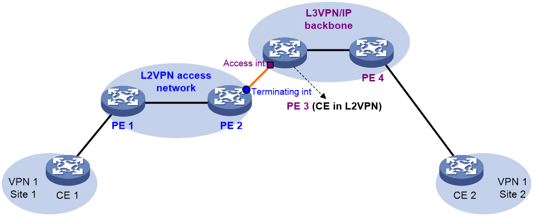
Conventional L2VPN access to L3VPN or IP backbone
In the conventional networking mode, two devices are required to connect the L2VPN and the L3VPN or IP backbone. One device terminates the L2VPN, and the other device provides access to the L3VPN or IP backbone.
As shown in Figure 1, the access network is an L2VPN. PE 1 and PE 2 are PE devices in the L2VPN. PE 1 is connected to VPN site 1. PE 2 is connected to the L3VPN/IP backbone through PE 3. PE 3 acts as a PE in the L3VPN/IP backbone and as a CE in the L2VPN at the same time.
A packet from VPN site 1 to VPN site 2 is forwarded as follows:
1. A user in VPN site 1 sends a packet to PE 1.
2. PE 1 adds an MPLS label to the packet and sends the packet through a PW to PE 2.
3. PE 2 removes the MPLS label or SID from the packet to obtain the original Layer 2 packet, and sends the packet to the connected CE (PE 3).
4. PE 3 looks up the routing table, and forwards the packet to the destination through the L3VPN or IP backbone.
Improved L2VPN access to L3VPN or IP backbone
As shown in Figure 2, the PE Aggregation (PE-agg) device connects the L2VPN with the L3VPN or IP backbone. PE-agg terminates the L2VPN and provides access to the L3VPN or IP backbone.
Configure the PE-agg as follows so the PE-agg can implement the functions of both PE 2 and PE 3 in Figure 1:
1. Create a terminating virtual Ethernet (VE) interface on the PE-agg to terminate L2VPN packets.
This interface is referred to as the VE-L2VPN (L2VE) interface. The functions and configurations of the interface are similar to those of the terminating interface (Terminating int) in Figure 1.
2. Create an access VE interface on the PE-agg to provide access to the backbone, and configure the interface and the L2VE interface have the same interface number.
This interface is referred to as the VE-L3VPN (L3VE) interface. The functions and configurations of the interface are similar to those of the access interface (Access int) in Figure 1. The IP address of the L3VE interface must be in the same network segment as the AC interface of CE 1. When the backbone is an L3VPN, bind the VPN instance to the L3VE interface. The interface can then forward user packets through the VPN routes.
The L2VE interface directly delivers the obtained Layer 2 packets to the L3VE interface. The two VE interfaces can be considered directly connected through a physical link.
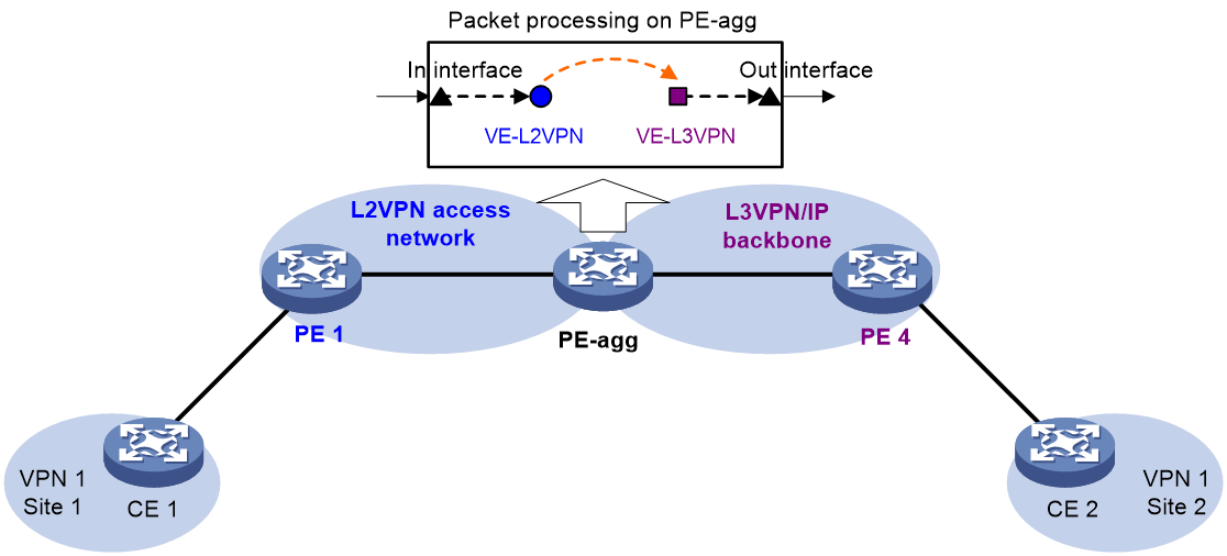
The PE-agg connects the L2VPN and the backbone through the L2VE interface and the L3VE interface. You can assume that the L2VPN is connected to the backbone through an Ethernet or VLAN link.
Configuring conventional L2VPN access to L3VPN or IP backbone
As shown in Figure 1, perform the following tasks to configure conventional L2VPN access to L3VPN or IP backbone:
1. Configure the L2VPN:
¡ Configure PE 1 and PE 2 as PE devices in the L2VPN.
¡ Configure CE 1 and PE 3 as CE devices in the L2VPN.
For more information about L2VPN configuration, see "Configuring MPLS L2VPN," "Configuring VPLS," EVPN VPWS configuration in EVPN Configuration Guide, and EVPN VPWS over SRv6 and EVPN VPLS over SRv6 configuration in Segment Routing Configuration Guide.
2. Configure the L3VPN or IP backbone:
¡ Configure PE 3 and PE 4 as PE devices in the L3VPN or IP backbone.
¡ Configure CE 1 and CE 2 as CE devices in the L3VPN or IP backbone.
For more information about L3VPN configuration, see "Configuring MPLS L3VPN," EVPN L3VPN configuration in EVPN Configuration Guide, and EVPN L3VPN over SRv6 configuration in Segment Routing Configuration Guide.
Configuring improved L2VPN access to L3VPN or IP backbone
Configuring L2VPN access to L3VPN or IP backbone through L2VE and L3VE interfaces
About this task
You can create the following types of L2VE and L3VE interfaces:
· Global L2VE and L3VE interfaces—Manages users accessed to all slots. A global L2VE or L3VE interface is named in L2VE A or L3VE A format, where A represents the interface number.
· Slot-based L2VE and L3VE interfaces—Manages users accessed to the specified slot. A slot-based L2VE or L3VE interface is named in L2VE A/B/C or L3VE A/B/C format, where A, B, and C represent the following:
¡ A represents the slot number.
¡ B is fixed at 0 by default.
¡ C represents the interface number on the slot.
Restrictions and guidelines
· The L2VE interface and L3VE interface created on the PE-agg must have the same interface number.
· To configure L2VPN access to L3VPN or IP backbone through multiple PWs, you must create multiple subinterfaces on the L2VE interface. All these subinterfaces on the L2VE interface must be connected to the same L3VE interface.
· The VPLS access to L3VPN or IP backbone model does not support creating L2VE subinterfaces.
· When packets entering an L3VPN or IP backbone carry VLAN tags, you must create an L3VE subinterface on the L3VE interface to terminate the VLAN tags. For more information about VLAN termination, see Layer 2—LAN Switching Configuration Guide.
In standard system operating mode, only the following cards support L2VE subinterfaces:
|
Card category |
Cards |
|
CEPC |
CEPC-CQ8L, CEPC-CQ8LA, CEPC-CQ8L1A, CEPC-CQ16L1 |
|
CSPEX |
CSPEX-1802X, CSPEX-1802XA, CSPEX-2612XA, CSPEX-1812X-E, CSPEX-2304X-G, CSPEX-1502XA |
|
SPE |
RX-SPE200-E |
In SDN-WAN system operating mode, only the following cards support L2VE subinterfaces:
|
Card category |
Cards |
|
CEPC |
CEPC-XP4LX, CEPC-XP24LX, CEPC-XP48RX, CEPC-CP4RX, CEPC-CP4RXA, CEPC-CP4RX-L, CEPC-CQ8L, CEPC-CQ8LA, CEPC-CQ8L1A, CEPC-CQ16L1 |
|
CSPEX |
CSPEX-1304X, CSPEX-1404X, CSPEX-1502X, CSPEX-1504X, CSPEX-1504XA, CSPEX-1602X, CSPEX-1602XA, CSPEX-1804X, CSPEX-1512X, CSPEX-1612X, CSPEX-1812X, CSPEX-1802X, CSPEX-1802XA, CSPEX-2612XA, CSPEX-1812X-E, CSPEX-2304X-G, CSPEX-1502XA |
|
SPE |
RX-SPE200, RX-SPE200-E |
In standard system operating mode, only the following cards support configuring transmission of ARP packets through both the primary and backup PWs:
|
Card category |
Cards |
|
CEPC |
CEPC-CQ8L, CEPC-CQ8LA, CEPC-CQ8L1A, CEPC-CQ16L1 |
|
CSPEX |
CSPEX-1802X, CSPEX-1802XA, CSPEX-2612XA, CSPEX-1812X-E, CSPEX-2304X-G, CSPEX-1502XA |
|
SPE |
RX-SPE200-E |
In SDN-WAN system operating mode, only the following cards support configuring transmission of ARP packets through both the primary and backup PWs:
|
Card category |
Cards |
|
CEPC |
CEPC-XP4LX, CEPC-XP24LX, CEPC-XP48RX, CEPC-CP4RX, CEPC-CP4RXA, CEPC-CP4RX-L, CEPC-CQ8L, CEPC-CQ8LA, CEPC-CQ8L1A, CEPC-CQ16L1 |
|
CSPEX |
CSPEX-1304X, CSPEX-1404X, CSPEX-1502X, CSPEX-1504X, CSPEX-1504XA, CSPEX-1602X, CSPEX-1602XA, CSPEX-1804X, CSPEX-1512X, CSPEX-1612X, CSPEX-1812X, CSPEX-1802X, CSPEX-1802XA, CSPEX-2612XA, CSPEX-1812X-E, CSPEX-2304X-G, CSPEX-1502XA |
|
SPE |
RX-SPE200, RX-SPE200-E |
Procedure
Configurations required on PEs and CEs are similar to those on the devices in the conventional L2VPN access scenario. The PE-agg requires the following configurations:
1. Create an L2VE interface:
a. Enter system view.
system-view
b. Create an L2VE interface or subinterface and enter its view.
interface ve-l2vpn { interface-number | interface-number.subnumber }
c. Bring up the interface.
undo shutdown
By default, the interface is up.
d. Return to system view.
quit
2. Create an L3VE interface:
a. Create an L3VE interface or subinterface and enter its view.
interface ve-l3vpn { interface-number | interface-number.subnumber }
b. Bring up the interface.
undo shutdown
By default, the interface is up.
c. Return to system view.
quit
3. Configure L2VPN.
For more information, see "Configuring MPLS L2VPN," "Configuring VPLS," EVPN VPWS configuration in EVPN Configuration Guide, and EVPN VPWS over SRv6 and EVPN VPLS over SRv6 configuration in Segment Routing Configuration Guide.
4. (Optional.) Configure transmission of ARP or ND packets through both the primary and backup PWs.
IPv4:
a. Enter system view.
system-view
b. Enter Layer 3 interface view.
interface interface-type interface-number
c. Configure transmission of ARP packets through both the primary and backup PWs.
l2vpn arp-dual-forward enable [ aging aging-time ]
By default, transmission of ARP packets through both the primary and backup PWs is disabled.
d. Return to system view.
quit
IPv6:
a. Enter system view.
system-view
b. Enter Layer 3 interface view.
interface interface-type interface-number
c. Configure transmission of ND packets through both the primary and backup PWs.
l2vpn nd-dual-forward enable [ aging aging-time ]
By default, transmission of ND packets through both the primary and backup PWs is disabled.
d. Return to system view.
quit
You can configure transmission of ARP or ND packets through both the primary and backup PWs only when the access network is an MPLS L2VPN network.
5. Configure L3VPN or IP routes.
For more information about L3VPN configuration, see "Configuring MPLS L3VPN," EVPN L3VPN configuration in EVPN Configuration Guide, and EVPN L3VPN over SRv6 configuration in Segment Routing Configuration Guide.
Enabling an L2VE interface to monitor PWs and SRv6 PWs
About this task
In a control-/user-plane separation (CUPS) network, the UP and CP uses a Layer 3 network (such as an IP network or L3VPN) to establish a control-/user-plane separation protocol (CUSP) channel. Deploy MPLS L2VPN, VPLS, or EVPN VPLS over SRv6 between the UP and the downstream device to establish a PW or an SRv6 PW. The UP uses L3VE interfaces (connected to the Layer 3 network) and L2VE interfaces (connected to the Layer 2 network) to interconnect the Layer 3 network and the Layer 2 network.
When a CP is connected to multiple UPs, traffic interruption will occur if the CP fails to detect the PW or SRv6 PW failure on an UP and selects the UP as the master UP. You can configure this feature to resolve this issue.
After you configure this feature on an L2VE interface bound to a VSI or cross-connect, the UP will monitor all PWs and SRv6 PWs on the VSI or cross-connect. When all PWs and SRv6 PWs on the VSI or cross-connect become down, the L2VE interface and its associated L3VE interface will also become down, and the UP will not be selected as the master UP.
Restrictions and guidelines
This feature does not take effect on an L2VE interface if the interface is not bound to a VSI through the xconnect vsi command or to a cross-connect through the ac interface command.
Both the track l2vpn-network-state command and the track pw-state srv6 command can enable an interface to monitor PWs and SRv6 PWs. The track l2vpn-network-state command takes effect even if you execute the track pw-state srv6 command. As a best practice, use the track l2vpn-network-state command to configure this feature.
Procedure
1. Enter system view.
system-view
2. Enter L2VE interface or subinterface view.
interface ve-l2vpn { interface-number | interface-number.subnumber }
3. Enable the interface to monitor PWs and SRv6 PWs. As a best practice, use the track l2vpn-network-state command to configure this feature.
track l2vpn-network-state (recommended) or track pw-state srv6
By default, an interface does not monitor PWs or SRv6 PWs.
Configuring an L2VE or L3VE interface
Restrictions and guidelines for L2VE or L3VE interface configuration
Only the following cards support creating slot-based L2VE and L3VE interfaces:
|
Card category |
Cards |
|
CEPC |
CEPC-CQ8L, CEPC-CQ8LA, CEPC-CQ8L1A, CEPC-CQ16L1 |
|
CSPEX |
CSPEX-1802X, CSPEX-1802XA, CSPEX-2612XA, CSPEX-1812X-E, CSPEX-2304X-G, CSPEX-1502XA |
|
SPE |
RX-SPE200-E |
Only the following device models support creating slot-based L2VE and L3VE interfaces:
· CR16010H-F (five switching fabric modules)
· CR16018-F (five switching fabric modules)
Slot-based L2VE and L3VE interfaces are not supported in IRF mode.
Slot-based L2VE subinterfaces are not supported in the current software version.
Configuring an L2VE interface
1. Enter system view.
system-view
2. Enter L2VE interface or subinterface view.
interface ve-l2vpn{ interface-number | interface-number.subnumber }
3. Configure the description of the interface.
description text
By default, the description of the interface is VE-L2VPNnumber Interface, for example, VE-L2VPN100 Interface.
4. Set the expected bandwidth for the interface.
bandwidth bandwidth-value
Configuring an L3VE interface
Restrictions and guidelines
If you configure the mtu size command in the view of an L3VE interface or subinterface, the command takes effect only on that L3VE interface or subinterface.
If you configure the mtu size spread command in the view of an L3VE interface, the command takes effect on the L3VE interface and all its subinterfaces.
For an L3VE subinterface, the MTU specified by the mtu size command takes precedence over that specified by the mtu size spread command.
When an L3VE interface or subinterface acts as both ingress and egress interfaces, IP packets will be fragmented with MTU 1280 bytes if the MTU for the egress interface is smaller than 1280 bytes. As a best practice, set the MTU for the egress interface to a value larger than 1280 bytes.
This feature is available only for the following cards:
|
Card category |
Cards |
|
CEPC |
CEPC-CQ8L, CEPC-CQ8LA, CEPC-CQ8L1A, CEPC-CQ16L1, CEPC-XP4LX, CEPC-XP24LX, CEPC-XP48RX, CEPC-CP4RX, CEPC-CP4RXA, CEPC-CP4RX-L |
|
CSPEX |
CSPEX-1802X, CSPEX-1802XA, CSPEX-2612XA, CSPEX-1812X-E, CSPEX-2304X-G, CSPEX-1502XA, CSPEX-1304X, CSPEX-1404X, CSPEX-1502X, CSPEX-1504X, CSPEX-1504XA, CSPEX-1602X, CSPEX-1602XA, CSPEX-1804X, CSPEX-1512X, CSPEX-1612X, CSPEX-1812X |
|
SPE |
RX-SPE200-E |
In standard system operating mode, the MAC address range is 000f-e2ff-8000 to 000f-e2ff-80ff for L3VE interfaces on the following cards:
|
Card category |
Cards |
|
CEPC |
CEPC-XP4LX, CEPC-XP24LX, CEPC-XP48RX, CEPC-CP4RX, CEPC-CP4RXA, CEPC-CP4RX-L |
|
CSPEX |
CSPEX-1304X, CSPEX-1404X, CSPEX-1502X, CSPEX-1504X, CSPEX-1504XA, CSPEX-1602X, CSPEX-1602XA, CSPEX-1804X, CSPEX-1512X, CSPEX-1612X, CSPEX-1812X |
You cannot directly configure MAC addresses for subinterfaces. All subinterfaces on an interface use the MAC address of the interface.
When configuring a MAC address for an interface, do not specify the MAC addresses reserved for VRRP.
Procedure
1. Enter system view.
system-view
2. Enter L3VE interface or subinterface view.
interface ve-l3vpn{ interface-number | interface-number.subnumber }
3. Configure the description of the interface.
description text
By default, the description of the interface is VE-L3VPNnumber Interface, for example, VE-L3VPN100 Interface.
4. Set the MTU.
¡ Set the MTU for an L3VE interface or subinterface.
mtu size
¡ Set the MTU for an L3VE interface and all its subinterfaces.
mtu size spread
L3VE subinterfaces do not support this command.
5. Set the MAC address for the L3VE interface.
mac-address mac-address
By default, the MAC address of an L3VE interface is allocated by the device.
6. Set the expected bandwidth for the interface.
bandwidth bandwidth-value
Restoring the default settings for an interface
Restrictions and guidelines
|
|
CAUTION: Restoring the default settings for an interface might interrupt ongoing network services. Make sure you are fully aware of the impact of the default command when you use it on a live network. |
This command might fail to restore the default settings for some commands for reasons such as command dependencies or system restrictions. Use the display this command in interface view to identify these commands. Use their undo forms or follow the command reference to restore their default settings. If your restoration attempt still fails, follow the error message instructions to resolve the problem.
Procedure
1. Enter system view.
system-view
2. Enter L2VE interface view, L2VE subinterface view, L3VE interface view, or L3VE subinterface view.
interface interface-type{ interface-number | interface-number.subnumber }
3. Restore the default settings for the interface.
Default
Configuring access to the public network or L3VPN
About this task
Configure an IP address for an L3VE subinterface and associate the L3VE subinterface to a VPN instance for access the public network or L3VPN.
Restrictions and guidelines
On a conventional L2VPN access to L3VPN or IP backbone network as shown in Figure 1, configure this feature on PE 3.
On an improved L2VPN access to L3VPN or IP backbone network as shown in Figure 2, configure this feature on the PE-agg.
Configuring network-side users to access the public network
1. Enter system view.
system-view
2. Enter L3VE subinterface view.
interface ve-l3vpn interface-number.subnumber
3. Configure an IP address for the interface.
ip address ip-address { mask-length | mask }
By default, no IP address is configured for the interface.
4. Configure a routing protocol to exchange routes with the CE accessing the MPLS L2VPN.
Available IPv4 routing protocols include static routing, RIP, OSPF, IS-IS, EBGP and IBGP. Available IPv6 routing protocols include IPv6 static routing, RIPng, OSPFv3, IPv6 IS-IS, EBGP, and IBGP. For more information about these routing protocols, see Layer 3—IP Routing Configuration Guide.
Configuring network-side users to access the L3VPN
1. Enter system view.
system-view
2. Enter L3VE subinterface view.
interface ve-l3vpn interface-number.subnumber
3. Associate a VPN instance with the interface.
ip binding vpn-instance vpn-instance-name
By default, an interface is not associated with a VPN instance and belongs to the public network.
|
|
CAUTION: Associating an interface with a VPN instance or disassociating an interface from a VPN instance will clear the IP address and routing protocol settings on the interface. |
The ip binding vpn-instance command deletes the IP address of the current interface. You must reconfigure an IP address for the interface after executing the command.
4. Configure an IP address for the interface
ip address ip-address { mask-length | mask }
By default, no IP address is configured for the interface.
Configuring fast forwarding for L2VPN access to L3VPN
Restrictions and guidelines
This feature is available only for the following cards:
|
Card category |
Cards |
|
CEPC |
CEPC-CQ8L, CEPC-CQ8LA, CEPC-CQ8L1A, CEPC-CQ16L1 |
|
CSPEX |
CSPEX-1802X, CSPEX-1802XA, CSPEX-2612XA, CSPEX-1812X-E, CSPEX-2304X-G, CSPEX-1502XA |
|
SPE |
RX-SPE200-E |
Enable this feature to improve the forwarding performance of L2VE and L3VE interfaces.
After this feature is enabled, the device does not support L3VE subinterfaces.
After enabling or disabling this feature, redeploy configuration to the L2VE and L3VE interfaces for the feature configuration to take effect.
After you enable this feature, L3VE interfaces on the device do not support uRPF. For more information about uRPF, see uRPF configuration in Security Configuration Guide.
After you enable this feature, the device does not support CGN. For more information about CGN, see NAT Configuration Guide.
Procedure
1. Enter system view.
system-view
2. Enable fast forwarding for L2VPN access to L3VPN.
l2vpn-l3vpn enhance-mode enable
By default, fast forwarding for L2VPN access to L3VPN is disabled.
Display and maintenance commands for L2VPN access to L3VPN or IP backbone
Execute display commands in any view and reset commands in user view.
|
Task |
Command |
|
Display information about L2VE interfaces. |
display interface [ ve-l2vpn [ interface-number | interface-number.subnumber ] ] [ brief [ description | down ] ] |
|
Display information about L3VE interfaces. |
display interface [ ve-l3vpn [ interface-number | interface-number.subnumber ] ] [ brief [ description | down ] ] |
|
Clear L2VE interface statistics. |
reset counters interface [ ve-l2vpn [ interface-number | interface-number.subnumber ] ] |
|
Clear L3VE interface statistics. |
reset counters interface [ ve-l3vpn [ interface-number | interface-number.subnumber ] ] |
Improved L2VPN access to L3VPN or IP backbone configuration examples
Example: Configuring access to MPLS L3VPN through an LDP MPLS L2VPN
The MPLS L2VPN in this configuration example is a point-to-point MPLS L2VPN.
Network configuration
The backbone is an MPLS L3VPN, which advertises VPN routes through BGP and forwards VPN packets based on MPLS labels. CE 1 and CE 2 belong to VPN 1 whose route target is 111:1 and RD is 200:1. CE 1 accesses the MPLS L2VPN through an Ethernet interface, and CE 2 is connected to the MPLS L3VPN through an Ethernet interface.
Perform the following configurations to allow communication between CE 1 and CE 2:
· Set up an LDP PW between PE 1 and PE-agg, so that CE 1 can access the MPLS L3VPN through MPLS L2VPN.
· Run EBGP between CE 1 and PE-agg and between CE 2 and PE 2 to exchange VPN routing information.
· Run IS-IS between PE-agg and PE 2 to ensure IP connectivity between the PEs, and run MP-IBGP between PE-agg and PE 2 to exchange VPN routing information.
· Run OSPF among PE 1, P, and PE-agg to ensure IP connectivity between the PEs.
Figure 3 Network diagram
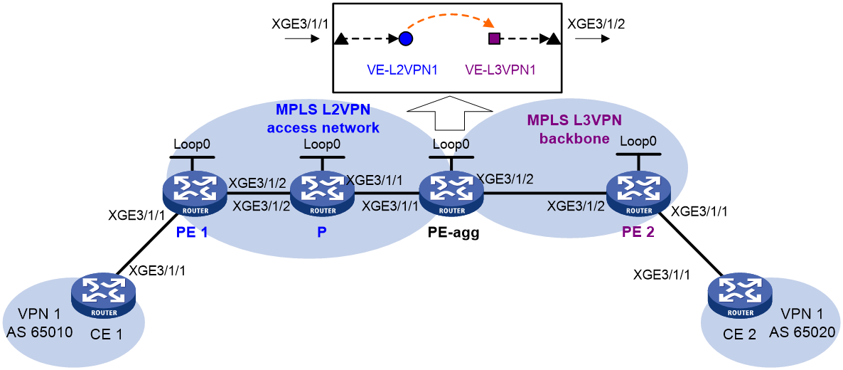
Table 1 Interface and IP address assignment
|
Device |
Interface |
IP address |
Device |
Interface |
IP address |
|
CE 1 |
XGE3/1/1 |
100.1.1.1/24 |
PE-agg |
Loop0 |
3.3.3.9/32 |
|
PE 1 |
Loop0 |
1.1.1.9/32 |
|
XGE3/1/1 |
10.2.2.2/24 |
|
|
XGE3/1/2 |
10.2.1.1/24 |
|
XGE3/1/2 |
10.3.3.1/24 |
|
P |
Loop0 |
2.2.2.9/32 |
|
VE-L3VPN1 |
100.1.1.2/24 |
|
|
XGE3/1/2 |
10.2.1.2/24 |
PE 2 |
Loop0 |
4.4.4.9/32 |
|
|
XGE3/1/1 |
10.2.2.1/24 |
|
XGE3/1/2 |
10.3.3.2/24 |
|
CE 2 |
XGE3/1/1 |
100.2.1.2/24 |
|
XGE3/1/1 |
100.2.1.1/24 |
Procedure
1. Configure IP addresses for interfaces as shown in Table 1. (Details not shown.)
2. Create VE-L2VPN 1 and VE-L3VPN 1 on PE-agg:
# Create interface VE-L2VPN 1.
<PEagg> system-view
[PEagg] interface ve-l2vpn 1
[PEagg-VE-L2VPN1] quit
# Create interface VE-L3VPN 1.
[PEagg] interface ve-l3vpn 1
[PEagg-VE-L3VPN1] quit
3. Configure MPLS L2VPN:
a. Configure OSPF on PE 1, P, and PE-agg, and advertise interface addresses:
# Configure PE 1.
<PE1> system-view
[PE1] ospf
[PE1-ospf-1] area 0
[PE1-ospf-1-area-0.0.0.0] network 1.1.1.9 0.0.0.0
[PE1-ospf-1-area-0.0.0.0] network 10.2.1.0 0.0.0.255
[PE1-ospf-1-area-0.0.0.0] quit
[PE1-ospf-1] quit
# Configure the P device.
<P> system-view
[P] ospf
[P-ospf-1] area 0
[P-ospf-1-area-0.0.0.0] network 2.2.2.9 0.0.0.0
[P-ospf-1-area-0.0.0.0] network 10.2.2.0 0.0.0.255
[P-ospf-1-area-0.0.0.0] network 10.2.1.0 0.0.0.255
[P-ospf-1-area-0.0.0.0] quit
[P-ospf-1] quit
# Configure PE-agg.
[PEagg] ospf
[PEagg-ospf-1] area 0
[PEagg-ospf-1-area-0.0.0.0] network 3.3.3.9 0.0.0.0
[PEagg-ospf-1-area-0.0.0.0] network 10.2.2.0 0.0.0.255
[PEagg-ospf-1-area-0.0.0.0] quit
[PEagg-ospf-1] quit
b. Configure basic MPLS and MPLS LDP on PE 1, P, and PE-agg:
# Configure PE 1.
[PE1] mpls lsr-id 1.1.1.9
[PE1] mpls ldp
[PE1-ldp] lsp-trigger all
[PE1-ldp] quit
[PE1] interface ten-gigabitethernet 3/1/2
[PE1-Ten-GigabitEthernet3/1/2] mpls enable
[PE1-Ten-GigabitEthernet3/1/2] mpls ldp enable
[PE1-Ten-GigabitEthernet3/1/2] quit
# Configure the P device.
[P] mpls lsr-id 2.2.2.9
[P] mpls ldp
[P-ldp] lsp-trigger all
[P-ldp] quit
[P] interface ten-gigabitethernet 3/1/1
[P-Ten-GigabitEthernet3/1/1] mpls enable
[P-Ten-GigabitEthernet3/1/1] mpls ldp enable
[P-Ten-GigabitEthernet3/1/1] quit
[P] interface ten-gigabitethernet 3/1/2
[P-Ten-GigabitEthernet3/1/2] mpls enable
[P-Ten-GigabitEthernet3/1/2] mpls ldp enable
[P-Ten-GigabitEthernet3/1/2] quit
# Configure PE-agg.
[PEagg] mpls lsr-id 3.3.3.9
[PEagg] mpls ldp
[PEagg-ldp] lsp-trigger all
[PEagg-ldp] quit
[PEagg] interface ten-gigabitethernet 3/1/1
[PEagg-Ten-GigabitEthernet3/1/1] mpls enable
[PEagg-Ten-GigabitEthernet3/1/1] mpls ldp enable
[PEagg-Ten-GigabitEthernet3/1/1] quit
c. Enable L2VPN on PE 1 and PE-agg:
# Configure PE 1.
[PE1] l2vpn enable
# Configure PE-agg.
[PEagg] l2vpn enable
d. Bind the AC to the PW on PE 1 and PE-agg:
# Create cross-connect group 1 on PE 1, create cross-connect 1 in cross-connect group 1, bind interface Ten-GigabitEthernet3/1/1 to cross-connect 1, and create an LDP PW on cross-connect 1 to bind the AC to the PW.
[PE1] xconnect-group 1
[PE1-xcg-1] connection 1
[PE1-xcg-1-1] ac interface ten-gigabitethernet 3/1/1
[PE1-xcg-1-1-Ten-GigabitEthernet3/1/1] quit
[PE1-xcg-1-1] peer 3.3.3.9 pw-id 101
[PE1-xcg-1-1-3.3.3.9-101] quit
# Create cross-connect group 1 on PE-agg, create cross-connect 1 in cross-connect group 1, bind interface VE-L2VPN 1 to cross-connect 1, and create an LDP PW on cross-connect 1 to bind the AC to the PW.
[PEagg] xconnect-group 1
[PEagg-xcg-1] connection 1
[PEagg-xcg-1-1] ac interface ve-l2vpn 1
[PEagg-xcg-1-1-VE-L2VPN1] quit
[PEagg-xcg-1-1] peer 1.1.1.9 pw-id 101
[PEagg-xcg-1-1-1.1.1.9-101] quit
4. Configure MPLS L3VPN:
a. Configure IS-IS on PE 2 and PE-agg, and advertise interface addresses:
# Configure PE-agg.
[PEagg] isis 1
[PEagg-isis-1] network-entity 10.0000.0000.0001.00
[PEagg-isis-1] quit
[PEagg] interface ten-gigabitethernet 3/1/2
[PEagg-Ten-GigabitEthernet3/1/2] isis enable 1
[PEagg-Ten-GigabitEthernet3/1/2] quit
[PEagg] interface loopback 0
[PEagg-LoopBack0] isis enable 1
[PEagg-LoopBack0] quit
# Configure PE 2.
[PE2] isis 1
[PE2-isis-1] network-entity 10.0000.0000.0002.00
[PE2-isis-1] quit
[PE2] interface ten-gigabitethernet 3/1/2
[PE2-Ten-GigabitEthernet3/1/2] isis enable 1
[PE2-Ten-GigabitEthernet3/1/2] quit
[PE2] interface loopback 0
[PE2-LoopBack0] isis enable 1
[PE2-LoopBack0] quit
b. Configure basic MPLS and MPLS LDP on PE-agg and PE 2:
# Configure PE-agg.
[PEagg] interface ten-gigabitethernet 3/1/2
[PEagg-Ten-GigabitEthernet3/1/2] mpls enable
[PEagg-Ten-GigabitEthernet3/1/2] mpls ldp enable
[PEagg-Ten-GigabitEthernet3/1/2] quit
# Configure PE 2.
[PE2] mpls lsr-id 4.4.4.9
[PE2] mpls ldp
[PE2-ldp] lsp-trigger all
[PE2-ldp] quit
[PE2] interface ten-gigabitethernet 3/1/2
[PE2-Ten-GigabitEthernet3/1/2] mpls enable
[PE2-Ten-GigabitEthernet3/1/2] mpls ldp enable
[PE2-Ten-GigabitEthernet3/1/2] quit
c. On PE-agg and PE 2, create VPN instance VPN1, and bind the VPN instance to the interface connected to the CE:
# Configure PE-agg.
[PEagg] ip vpn-instance VPN1
[PEagg-vpn-instance-VPN1] route-distinguisher 200:1
[PEagg-vpn-instance-VPN1] vpn-target 111:1 both
[PEagg-vpn-instance-VPN1] quit
[PEagg] interface ve-l3vpn 1
[PEagg-VE-L3VPN1] ip binding vpn-instance VPN1
[PEagg-VE-L3VPN1] ip address 100.1.1.2 24
# Configure PE 2.
[PE2] ip vpn-instance VPN1
[PE2-vpn-instance-VPN1] route-distinguisher 200:1
[PE2-vpn-instance-VPN1] vpn-target 111:1 both
[PE2-vpn-instance-VPN1] quit
[PE2] interface ten-gigabitethernet 3/1/1
[PE2-Ten-GigabitEthernet3/1/1] ip binding vpn-instance VPN1
[PE2-Ten-GigabitEthernet3/1/1] ip address 100.2.1.1 24
[PE2-Ten-GigabitEthernet3/1/1] quit
d. Establish EBGP peer relationships between PEs and CEs to redistribute VPN routes:
# Configure CE 1 and specify PE-agg as the peer.
<CE1> system-view
[CE1] bgp 65010
[CE1-bgp] peer 100.1.1.2 as-number 100
[CE1-bgp] address-family ipv4
[CE1-bgp-ipv4] peer 100.1.1.2 enable
[CE1-bgp-ipv4] import-route direct
[CE1-bgp-ipv4] quit
[CE1-bgp] quit
# Configure PE-agg and specify CE 1 as the peer.
[PEagg] bgp 100
[PEagg-bgp] ip vpn-instance VPN1
[PEagg-bgp-VPN1] peer 100.1.1.1 as-number 65010
[PEagg-bgp-VPN1] address-family ipv4
[PEagg-bgp-ipv4-VPN1] peer 100.1.1.1 enable
[PEagg-bgp-ipv4-VPN1] import-route direct
[PEagg-bgp-ipv4-VPN1] quit
[PEagg-bgp-VPN1] quit
[PEagg-bgp] quit
# Configure CE 2 and specify PE 2 as the peer.
[CE2] bgp 65020
[CE2-bgp] peer 100.2.1.1 as-number 100
[CE2-bgp] address-family ipv4
[CE2-bgp-ipv4] peer 100.2.1.1 enable
[CE2-bgp-ipv4] import-route direct
[CE2-bgp-ipv4] quit
[CE2-bgp] quit
# Configure PE 2 and specify CE 2 as the peer.
[PE2] bgp 100
[PE2-bgp] ip vpn-instance VPN1
[PE2-bgp-VPN1] peer 100.2.1.2 as-number 65020
[PE2-bgp-VPN1] address-family ipv4
[PE2-bgp-ipv4-VPN1] peer 100.2.1.2 enable
[PE2-bgp-ipv4-VPN1] import-route direct
[PE2-bgp-ipv4-VPN1] quit
[PE2-bgp-VPN1] quit
[PE2-bgp] quit
e. Establish an MP-IBGP peer relationship between PE-agg and PE 2:
# Configure PE-agg.
[PEagg] bgp 100
[PEagg-bgp] peer 4.4.4.9 as-number 100
[PEagg-bgp] peer 4.4.4.9 connect-interface loopback 0
[PEagg-bgp] address-family vpnv4
[PEagg-bgp-vpnv4] peer 4.4.4.9 enable
[PEagg-bgp-vpnv4] quit
[PEagg-bgp] quit
# Configure PE 2.
[PE2] bgp 100
[PE2-bgp] peer 3.3.3.9 as-number 100
[PE2-bgp] peer 3.3.3.9 connect-interface loopback 0
[PE2-bgp] address-family vpnv4
[PE2-bgp-vpnv4] peer 3.3.3.9 enable
[PE2-bgp-vpnv4] quit
[PE2-bgp] quit
5. The default MTU value varies by interface type. To avoid packet fragmentation, set the MTU value for each interface on each device to 1500 bytes. The following shows the MTU configuration on PE 1.
[PE1] interface ten-gigabitethernet 3/1/2
[PE1-Ten-GigabitEthernet3/1/2] mtu 1500
[PE1-Ten-GigabitEthernet3/1/2] shutdown
[PE1-Ten-GigabitEthernet3/1/2] undo shutdown
Verifying the configuration
# Ping CE 2 from CE 1 to verify their connectivity.
<CE1> ping 100.2.1.2
Ping 100.2.1.2 (100.2.1.2): 56 data bytes, press CTRL_C to break
56 bytes from 100.2.1.2: icmp_seq=0 ttl=128 time=1.073 ms
56 bytes from 100.2.1.2: icmp_seq=1 ttl=128 time=1.428 ms
56 bytes from 100.2.1.2: icmp_seq=2 ttl=128 time=19.367 ms
56 bytes from 100.2.1.2: icmp_seq=3 ttl=128 time=1.013 ms
56 bytes from 100.2.1.2: icmp_seq=4 ttl=128 time=0.684 ms
--- Ping statistics for 100.2.1.2 ---
5 packet(s) transmitted, 5 packet(s) received, 0.0% packet loss
round-trip min/avg/max/std-dev = 0.684/4.713/19.367/7.331 ms
Example: Configuring access to IP backbone through an LDP VPLS
Network configuration
Create an LDP PW between PE 1 and PE-agg on the VPLS access network, so that CE 1 can access the IP backbone through the PW.
Configure OSPF process 2 to advertise routing information on the IP backbone.
Figure 4 Network diagram
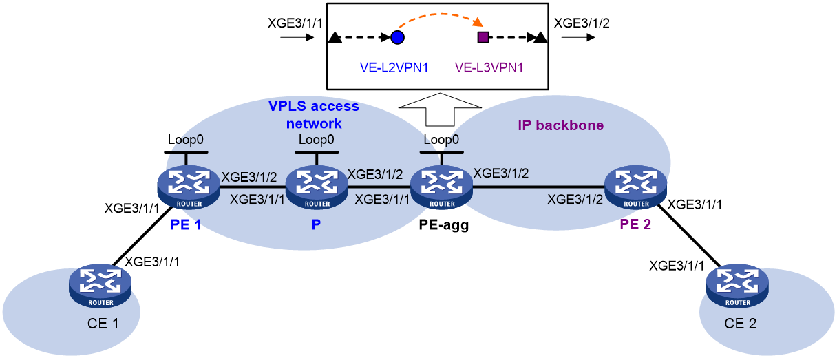
Table 2 Interface and IP address assignment
|
Device |
Interface |
IP address |
Device |
Interface |
IP address |
|
CE 1 |
XGE3/1/1 |
100.1.1.1/24 |
PE-agg |
Loop0 |
3.3.3.9/32 |
|
PE 1 |
Loop0 |
1.1.1.9/32 |
|
XGE3/1/1 |
10.2.2.2/24 |
|
|
XGE3/1/2 |
10.2.1.1/24 |
|
XGE3/1/2 |
10.3.3.1/24 |
|
P |
Loop0 |
2.2.2.9/32 |
|
VE-L3VPN1 |
100.1.1.2/24 |
|
|
XGE3/1/1 |
10.2.1.2/24 |
PE 2 |
XGE3/1/2 |
10.3.3.2/24 |
|
|
XGE3/1/2 |
10.2.2.1/24 |
|
XGE3/1/1 |
100.2.1.1/24 |
|
CE 2 |
XGE3/1/1 |
100.2.1.2/24 |
|
|
|
Procedure
1. Configure IP addresses for interfaces as shown in Table 2. (Details not shown.)
2. Create VE-L2VPN 1 and VE-L3VPN 1 on PE-agg:
# Create VE-L2VPN 1.
<PEagg> system-view
[PEagg] interface ve-l2vpn 1
[PEagg-VE-L2VPN1] quit
# Create VE-L3VPN 1, and configure an IP address for the interface.
[PEagg] interface ve-l3vpn 1
[PEagg-VE-L3VPN1] ip address 100.1.1.2 24
[PEagg-VE-L3VPN1] quit
3. Configure MPLS L2VPN:
a. Configure OSPF on PE 1, P, and PE-agg, and advertise interface addresses:
# Configure PE 1.
<PE1> system-view
[PE1] ospf
[PE1-ospf-1] area 0
[PE1-ospf-1-area-0.0.0.0] network 1.1.1.9 0.0.0.0
[PE1-ospf-1-area-0.0.0.0] network 10.2.1.0 0.0.0.255
[PE1-ospf-1-area-0.0.0.0] quit
[PE1-ospf-1] quit
# Configure the P device.
<P> system-view
[P] ospf
[P-ospf-1] area 0
[P-ospf-1-area-0.0.0.0] network 2.2.2.9 0.0.0.0
[P-ospf-1-area-0.0.0.0] network 10.2.2.0 0.0.0.255
[P-ospf-1-area-0.0.0.0] network 10.2.1.0 0.0.0.255
[P-ospf-1-area-0.0.0.0] quit
[P-ospf-1] quit
# Configure PE-agg.
[PEagg] ospf
[PEagg-ospf-1] area 0
[PEagg-ospf-1-area-0.0.0.0] network 3.3.3.9 0.0.0.0
[PEagg-ospf-1-area-0.0.0.0] network 10.2.2.0 0.0.0.255
[PEagg-ospf-1-area-0.0.0.0] quit
[PEagg-ospf-1] quit
b. Configure basic MPLS and MPLS LDP on PE 1, P, and PE-agg:
# Configure PE 1.
[PE1] mpls lsr-id 1.1.1.9
[PE1] mpls ldp
[PE1-ldp] lsp-trigger all
[PE1-ldp] quit
[PE1] interface ten-gigabitethernet 3/1/2
[PE1-Ten-GigabitEthernet3/1/2] mpls enable
[PE1-Ten-GigabitEthernet3/1/2] mpls ldp enable
[PE1-Ten-GigabitEthernet3/1/2] quit
# Configure the P device.
[P] mpls lsr-id 2.2.2.9
[P] mpls ldp
[P-ldp] lsp-trigger all
[P-ldp] quit
[P] interface ten-gigabitethernet 3/1/1
[P-Ten-GigabitEthernet3/1/1] mpls enable
[P-Ten-GigabitEthernet3/1/1] mpls ldp enable
[P-Ten-GigabitEthernet3/1/1] quit
[P] interface Ten-GigabitEthernet3/1/2
[P-Ten-GigabitEthernet3/1/2] mpls enable
[P-Ten-GigabitEthernet3/1/2] mpls ldp enable
[P-Ten-GigabitEthernet3/1/2] quit
# Configure PE-agg.
[PEagg] mpls lsr-id 3.3.3.9
[PEagg] mpls ldp
[PEagg-ldp] lsp-trigger all
[PEagg-ldp] quit
[PEagg] interface ten-gigabitethernet 3/1/1
[PEagg-Ten-GigabitEthernet3/1/1] mpls enable
[PEagg-Ten-GigabitEthernet3/1/1] mpls ldp enable
[PEagg-Ten-GigabitEthernet3/1/1] quit
c. Enable L2VPN on PE 1 and PE-agg:
# Configure PE 1.
[PE1] l2vpn enable
# Configure PE-agg.
[PEagg] l2vpn enable
d. Create VSIs on PE 1 and PE-agg:
# On PE 1, create VSI vpna, and specify the PW signaling protocol for the VSI as LDP.
[PE1] vsi vpna
[PE1-vsi-vpna] pwsignaling ldp
# On PE 1, create LDP PW 500 to the peer PE 3.3.3.9.
[PE1-vsi-vpna-ldp] peer 3.3.3.9 pw-id 500
[PE1-vsi-vpna-ldp-3.3.3.9-500] quit
[PE1-vsi-vpna-ldp] quit
[PE1-vsi-vpna] quit
# On PE-agg, create VSI vpna, and specify the PW signaling protocol for the VSI as LDP.
[PEagg] vsi vpna
[PEagg-vsi-vpna] pwsignaling ldp
# On PE-agg, create an LDP PW: specify the peer PE address as 1.1.1.9, and set the PW ID to 500.
[PEagg-vsi-vpna-ldp] peer 1.1.1.9 pw-id 500
[PEagg-vsi-vpna-ldp-1.1.1.9-500] quit
[PEagg-vsi-vpna-ldp] quit
[PEagg-vsi-vpna] quit
e. Bind the AC interface to the VSI on PE 1 and PE-agg:
# On PE 1, bind Ten-GigabitEthernet 3/1/1 to VSI vpna.
[PE1] interface ten-gigabitethernet 3/1/1
[PE1-Ten-GigabitEthernet3/1/1] xconnect vsi vpna
[PE1-Ten-GigabitEthernet3/1/1] quit
# On PE-agg, bind VE-L2VPN 1 to VSI vpna.
[PEagg] interface ve-l2vpn 1
[PEagg-VE-L2VPN1] xconnect vsi vpna
[PEagg-VE-L2VPN1] quit
4. Configure OSPF process 2 to advertise routing information on the IP backbone:
# Configure CE 1.
[CE1] ospf 2
[CE1-ospf-2] area 0
[CE1-ospf-2-area-0.0.0.0] network 100.1.1.0 0.0.0.255
[CE1-ospf-2-area-0.0.0.0] quit
[CE1-ospf-2] quit
# Configure PE-agg.
[PEagg] ospf 2
[PEagg-ospf-2] area 0
[PEagg-ospf-2-area-0.0.0.0] network 100.1.1.0 0.0.0.255
[PEagg-ospf-2-area-0.0.0.0] network 10.3.3.0 0.0.0.255
[PEagg-ospf-2-area-0.0.0.0] quit
[PEagg-ospf-2] quit
# Configure PE 2.
<PE2> system-view
[PE2] ospf 2
[PE2-ospf-2] area 0
[PE2-ospf-2-area-0.0.0.0] network 100.2.1.0 0.0.0.255
[PE2-ospf-2-area-0.0.0.0] network 10.3.3.0 0.0.0.255
[PE2-ospf-2-area-0.0.0.0] quit
[PE2-ospf-2] quit
# Configure CE 2.
<CE2> system-view
[CE2] ospf 2
[CE2-ospf-2] area 0
[CE2-ospf-2-area-0.0.0.0] network 100.2.1.0 0.0.0.255
[CE2-ospf-2-area-0.0.0.0] quit
[CE2-ospf-2] quit
5. The default MTU value varies by interface type. To avoid packet fragmentation, set the MTU value for each interface on each device to 1500 bytes. The following shows the MTU configuration on PE 1.
[PE1] interface ten-gigabitethernet 3/1/2
[PE1-Ten-GigabitEthernet3/1/2] mtu 1500
[PE1-Ten-GigabitEthernet3/1/2] shutdown
[PE1-Ten-GigabitEthernet3/1/2] undo shutdown
Verifying the configuration
# Ping CE 2 from CE 1 to verify their connectivity.
<CE1> ping 100.2.1.2
Ping 100.2.1.2 (100.2.1.2): 56 data bytes, press CTRL_C to break
56 bytes from 100.2.1.2: icmp_seq=0 ttl=128 time=1.073 ms
56 bytes from 100.2.1.2: icmp_seq=1 ttl=128 time=1.428 ms
56 bytes from 100.2.1.2: icmp_seq=2 ttl=128 time=19.367 ms
56 bytes from 100.2.1.2: icmp_seq=3 ttl=128 time=1.013 ms
56 bytes from 100.2.1.2: icmp_seq=4 ttl=128 time=0.684 ms
--- Ping statistics for 100.2.1.2 ---
5 packet(s) transmitted, 5 packet(s) received, 0.0% packet loss
round-trip min/avg/max/std-dev = 0.684/4.713/19.367/7.331 ms
Example: Configuring LDP PW access to IP backbone through L2VE subinterfaces
Network configuration
Create LDP PWs between PE 1 and PE-agg on the L2VPN access network, so that CE 1 and CE 2 can access the IP backbone through the PWs.
Configure L2VPN access to the IP backbone through L2VE subinterfaces.
Configure OSPF process 2 to advertise routing information on the IP backbone.
Figure 5 Network diagram
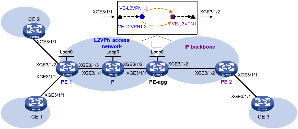
Table 3 Interface and IP address assignment
|
Device |
Interface |
IP address |
Device |
Interface |
IP address |
|
CE 1 |
XGE3/1/1 |
100.1.1.1/24 |
CE 2 |
XGE3/1/1 |
100.1.1.2/24 |
|
PE 1 |
Loop0 |
1.1.1.9/32 |
PE-agg |
Loop0 |
3.3.3.9/32 |
|
|
XGE3/1/3 |
10.2.1.1/24 |
|
XGE3/1/1 |
10.2.2.2/24 |
|
P |
Loop0 |
2.2.2.9/32 |
|
XGE3/1/2 |
10.3.3.1/24 |
|
|
XGE3/1/1 |
10.2.1.2/24 |
|
VE-L3VPN1 |
100.1.1.3/24 |
|
|
XGE3/1/2 |
10.2.2.1/24 |
PE 2 |
XGE3/1/2 |
10.3.3.2/24 |
|
CE 3 |
XGE3/1/1 |
100.2.1.2/24 |
|
XGE3/1/1 |
100.2.1.1/24 |
Procedure
1. Configure IP addresses for interfaces as shown in Table 3. (Details not shown.)
2. Create VE-L2VPN 1 and VE-L3VPN 1 on PE-agg:
# Create VE-L2VPN 1, VE-L2VPN 1.1, and VE-L2VPN 1.2.
<PEagg> system-view
[PEagg] interface ve-l2vpn 1
[PEagg-VE-L2VPN1] quit
[PEagg] interface ve-l2vpn 1.1
[PEagg-VE-L2VPN1.1] quit
[PEagg] interface ve-l2vpn 1.2
[PEagg-VE-L2VPN1.2] quit
# Create VE-L3VPN 1, and configure an IP address for the interface.
[PEagg] interface ve-l3vpn 1
[PEagg-VE-L3VPN1] ip address 100.1.1.3 24
[PEagg-VE-L3VPN1] quit
3. Configure MPLS L2VPN:
a. Configure OSPF on PE 1, P, and PE-agg, and advertise interface addresses:
# Configure PE 1.
<PE1> system-view
[PE1] ospf
[PE1-ospf-1] area 0
[PE1-ospf-1-area-0.0.0.0] network 1.1.1.9 0.0.0.0
[PE1-ospf-1-area-0.0.0.0] network 10.2.1.0 0.0.0.255
[PE1-ospf-1-area-0.0.0.0] quit
[PE1-ospf-1] quit
# Configure the P device.
<P> system-view
[P] ospf
[P-ospf-1] area 0
[P-ospf-1-area-0.0.0.0] network 2.2.2.9 0.0.0.0
[P-ospf-1-area-0.0.0.0] network 10.2.2.0 0.0.0.255
[P-ospf-1-area-0.0.0.0] network 10.2.1.0 0.0.0.255
[P-ospf-1-area-0.0.0.0] quit
[P-ospf-1] quit
# Configure PE-agg.
[PEagg] ospf
[PEagg-ospf-1] area 0
[PEagg-ospf-1-area-0.0.0.0] network 3.3.3.9 0.0.0.0
[PEagg-ospf-1-area-0.0.0.0] network 10.2.2.0 0.0.0.255
[PEagg-ospf-1-area-0.0.0.0] quit
[PEagg-ospf-1] quit
b. Configure basic MPLS and MPLS LDP on PE 1, P, and PE-agg:
# Configure PE 1.
[PE1] mpls lsr-id 1.1.1.9
[PE1] mpls ldp
[PE1-ldp] lsp-trigger all
[PE1-ldp] quit
[PE1] interface ten-gigabitethernet 3/1/3
[PE1-Ten-GigabitEthernet3/1/3] mpls enable
[PE1-Ten-GigabitEthernet3/1/3] mpls ldp enable
[PE1-Ten-GigabitEthernet3/1/3] quit
# Configure the P device.
[P] mpls lsr-id 2.2.2.9
[P] mpls ldp
[P-ldp] lsp-trigger all
[P-ldp] quit
[P] interface ten-gigabitethernet 3/1/1
[P-Ten-GigabitEthernet3/1/1] mpls enable
[P-Ten-GigabitEthernet3/1/1] mpls ldp enable
[P-Ten-GigabitEthernet3/1/1] quit
[P] interface ten-gigabitethernet 3/1/2
[P-Ten-GigabitEthernet3/1/2] mpls enable
[P-Ten-GigabitEthernet3/1/2] mpls ldp enable
[P-Ten-GigabitEthernet3/1/2] quit
# Configure PE-agg.
[PEagg] mpls lsr-id 3.3.3.9
[PEagg] mpls ldp
[PEagg-ldp] lsp-trigger all
[PEagg-ldp] quit
[PEagg] interface ten-gigabitethernet 3/1/1
[PEagg-Ten-GigabitEthernet3/1/1] mpls enable
[PEagg-Ten-GigabitEthernet3/1/1] mpls ldp enable
[PEagg-Ten-GigabitEthernet3/1/1] quit
c. Enable L2VPN on PE 1 and PE-agg:
# Configure PE 1.
[PE1] l2vpn enable
# Configure PE-agg.
[PEagg] l2vpn enable
d. Create cross-connect groups on PE 1 and PE-agg:
# On PE-agg, create a cross-connect group named vpna, create a cross-connect named ldp in the group, and bind VE-L2VPN 1.1 to the cross-connect.
[PEagg] xconnect-group vpna
[PEagg-xcg-vpna] connection ldp
[PEagg-xcg-vpna-ldp] ac interface ve-l2vpn 1.1
[PEagg-xcg-vpna-ldp-VE-L2VPN1.1] quit
# On PE-agg, create an LDP PW for the cross-connect to bind the AC to the PW.
[PEagg-xcg-vpna-ldp] peer 1.1.1.9 pw-id 500
[PEagg-xcg-vpna-ldp-1.1.1.9-500] quit
[PEagg-xcg-vpna-ldp] quit
[PEagg-xcg-vpna] quit
# On PE-agg, create a cross-connect group named vpnb, create a cross-connect named ldp in the group, and bind VE-L2VPN 1.2 to the cross-connect.
[PEagg] xconnect-group vpnb
[PEagg-xcg-vpnb] connection ldp
[PEagg-xcg-vpnb-ldp] ac interface ve-l2vpn 1.2
[PEagg-xcg-vpnb-ldp-VE-L2VPN1.2] quit
# On PE-agg, create an LDP PW for the cross-connect to bind the AC to the PW.
[PEagg-xcg-vpnb-ldp] peer 1.1.1.9 pw-id 501
[PEagg-xcg-vpnb-ldp-1.1.1.9-501] quit
[PEagg-xcg-vpnb-ldp] quit
[PEagg-xcg-vpnb] quit
# On PE 1, create a cross-connect group named vpna, create a cross-connect named ldp in the group, and bind Ten-GigabitEthernet 3/1/1 to the cross-connect.
[PE1] xconnect-group vpna
[PE1-xcg-vpna] connection ldp
[PE1-xcg-vpna-ldp] ac interface ten-gigabitethernet 3/1/1
[PE1-xcg-vpna-ldp-Ten-GigabitEthernet3/1/1] quit
# On PE 1, create an LDP PW for the cross-connect to bind the AC to the PW.
[PE1-xcg-vpna-ldp] peer 3.3.3.9 pw-id 500
[PE1-xcg-vpna-ldp-3.3.3.9-500] quit
[PE1-xcg-vpna-ldp] quit
[PE1-xcg-vpna] quit
# On PE 1, create a cross-connect group named vpnb, create a cross-connect named ldp in the group, and bind Ten-GigabitEthernet 3/1/2 to the cross-connect.
[PE1]xconnect-group vpnb
[PE1-xcg-vpnb]connection ldp
[PE1-xcg-vpnb-ldp] ac interface ten-gigabitethernet 3/1/2
[PE1-xcg-vpnb-ldp-Ten-GigabitEthernet3/1/2] quit
# On PE 1, create an LDP PW for the cross-connect to bind the AC to the PW.
[PE1-xcg-vpnb-ldp] peer 3.3.3.9 pw-id 501
[PE1-xcg-vpnb-ldp-3.3.3.9-500] quit
[PE1-xcg-vpnb-ldp] quit
[PE1-xcg-vpnb] quit
4. Configure OSPF process 2 to advertise routing information on the IP backbone:
# Configure CE 1.
[CE1] ospf 2
[CE1-ospf-2] area 0
[CE1-ospf-2-area-0.0.0.0] network 100.1.1.0 0.0.0.255
[CE1-ospf-2-area-0.0.0.0] quit
[CE1-ospf-2] quit
# Configure PE-agg.
[PEagg] ospf 2
[PEagg-ospf-2] area 0
[PEagg-ospf-2-area-0.0.0.0] network 100.1.1.0 0.0.0.255
[PEagg-ospf-2-area-0.0.0.0] network 10.3.3.0 0.0.0.255
[PEagg-ospf-2-area-0.0.0.0] quit
[PEagg-ospf-2] quit
# Configure PE 2.
<PE2> system-view
[PE2] ospf 2
[PE2-ospf-2] area 0
[PE2-ospf-2-area-0.0.0.0] network 100.2.1.0 0.0.0.255
[PE2-ospf-2-area-0.0.0.0] network 10.3.3.0 0.0.0.255
[PE2-ospf-2-area-0.0.0.0] quit
[PE2-ospf-2] quit
# Configure CE 2.
<CE2> system-view
[CE2] ospf 2
[CE2-ospf-2] area 0
[CE2-ospf-2-area-0.0.0.0] network 100.2.1.0 0.0.0.255
[CE2-ospf-2-area-0.0.0.0] quit
[CE2-ospf-2] quit
5. The default MTU value varies by interface type. To avoid packet fragmentation, set the MTU value for each interface on each device to 1500 bytes. The following shows the MTU configuration on PE 1.
[PE1] interface ten-gigabitethernet 3/1/3
[PE1-Ten-GigabitEthernet3/1/3] mtu 1500
[PE1-Ten-GigabitEthernet3/1/3] shutdown
[PE1-Ten-GigabitEthernet3/1/3] undo shutdown
Verifying the configuration
# Ping CE 3 from CE 1 and CE 2 to verify the connectivity. This example uses CE 1.
<CE1> ping 100.2.1.2
Ping 100.2.1.2 (100.2.1.2): 56 data bytes, press CTRL_C to break
56 bytes from 100.2.1.2: icmp_seq=0 ttl=128 time=1.073 ms
56 bytes from 100.2.1.2: icmp_seq=1 ttl=128 time=1.428 ms
56 bytes from 100.2.1.2: icmp_seq=2 ttl=128 time=19.367 ms
56 bytes from 100.2.1.2: icmp_seq=3 ttl=128 time=1.013 ms
56 bytes from 100.2.1.2: icmp_seq=4 ttl=128 time=0.684 ms
--- Ping statistics for 100.2.1.2 ---
5 packet(s) transmitted, 5 packet(s) received, 0.0% packet loss
round-trip min/avg/max/std-dev = 0.684/4.713/19.367/7.331 ms
Example: Configuring LDP PW access to shared gateway in IP backbone through L2VE interfaces
Network configuration
Create primary and backup LDP PWs between PE 1 and PE-agg on the L2VPN access network, so that CE 1 can access the IP backbone through the PWs.
Configure L2VPN access to the IP backbone through L2VE interfaces.
Configure OSPF process 2 to advertise routing information on the IP backbone.
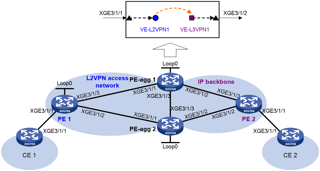
Table 4 Interface and IP address assignment
|
Device |
Interface |
IP address |
Device |
Interface |
IP address |
|
CE 1 |
XGE3/1/1 |
100.1.1.1/24 |
CE 2 |
XGE3/1/1 |
100.1.2.2/24 |
|
PE 1 |
Loop0 |
1.1.1.1/32 |
PE 2 |
XGE3/1/1 |
100.1.2.1/24 |
|
|
XGE3/1/3 |
10.1.1.1/24 |
|
XGE3/1/3 |
10.1.3.2/24 |
|
|
XGE3/1/2 |
10.1.2.1/24 |
|
XGE3/1/2 |
10.1.4.2/24 |
|
PE-agg 1 |
Loop0 |
2.2.2.2/32 |
PE-agg 2 |
Loop0 |
3.3.3.3/32 |
|
|
XGE3/1/1 |
10.1.1.2/24 |
|
XGE3/1/1 |
10.1.2.2/24 |
|
|
XGE3/1/2 |
10.1.3.1/24 |
|
XGE3/1/2 |
10.1.4.1/24 |
|
|
XGE3/1/3 |
20.1.1.1/24 |
|
XGE3/1/3 |
20.1.1.2/24 |
Procedure
1. Configure IP addresses for interfaces as shown in Figure 6. (Details not shown.)
2. Configure CE 1:
# Configure OSPF process 2 to advertise routing information.
[CE1] ospf
[CE1-ospf-2] area 0
[CE1-ospf-2-area-0.0.0.0] network 100.1.1.0 0.0.0.255
[CE1-ospf-2-area-0.0.0.0] quit
[CE1-ospf-2] quit
3. Configure PE 1:
# Configure an LSR ID.
<PE1> system-view
[PE1] mpls lsr-id 1.1.1.1
# Enable L2VPN.
[PE1] l2vpn enable
# Enable LDP globally.
[PE1] mpls ldp
[PE1-ldp] quit
# Enable MPLS and LDP on the interfaces.
[PE1] interface ten-gigabitethernet 3/1/3
[PE1-Ten-GigabitEthernet3/1/3] mpls enable
[PE1-Ten-GigabitEthernet3/1/3] mpls ldp enable
[PE1-Ten-GigabitEthernet3/1/3] quit
[PE1] interface ten-gigabitethernet 3/1/2
[PE1-Ten-GigabitEthernet3/1/2] mpls enable
[PE1-Ten-GigabitEthernet3/1/2] mpls ldp enable
[PE1-Ten-GigabitEthernet3/1/2] quit
# Configure OSPF.
[PE1] ospf
[PE1-ospf-1] area 0
[PE1-ospf-1-area-0.0.0.0] network 10.1.1.1 0.0.0.255
[PE1-ospf-1-area-0.0.0.0] network 10.1.2.1 0.0.0.255
[PE1-ospf-1-area-0.0.0.0] network 1.1.1.1 0.0.0.0
[PE1-ospf-1-area-0.0.0.0] quit
[PE1-ospf-1] quit
# Create a cross-connect group named vpna, create a cross-connect named ldp in the group, and bind interface Ten-GigabitEthernet 3/1/1 to the cross-connect.
[PE1] xconnect-group vpna
[PE1-xcg-vpna] connection ldp
[PE1-xcg-vpna-ldp] ac interface ten-gigabitethernet 3/1/1
[PE1-xcg-vpna-ldp-Ten-GigabitEthernet3/1/1] quit
# Create an LDP PW, configure a backup PW for the LDP PW, and enable the dual receive feature for PW redundancy.
[PE1-xcg-vpna-ldp] protection dual-receive
[PE1-xcg-vpna-ldp] peer 2.2.2.2 pw-id 11
[PE1-xcg-vpna-ldp-2.2.2.2-11] backup-peer 3.3.3.3 pw-id 22
[PE1-xcg-vpna-ldp-2.2.2.2-11-backup] quit
[PE1-xcg-vpna-ldp-2.2.2.2-11] quit
[PE1-xcg-vpna-ldp] quit
[PE1-xcg-vpna] quit
4. Configure PE-agg 1:
# Create interface VE-L2VPN 1.
<PE-agg1> system-view
[PE-agg1] interface ve-l2vpn 1
[PE-agg1-VE-L2VPN1] quit
# Configure OSPF process 1 to advertise routing information in the L2VPN network.
[PE-agg1] ospf
[PE-agg1-ospf-1] area 0
[PE-agg1-ospf-1-area-0.0.0.0] network 2.2.2.2 0.0.0.0
[PE-agg1-ospf-1-area-0.0.0.0] network 10.1.1.0 0.0.0.255
[PE-agg1-ospf-1-area-0.0.0.0] network 20.1.1.0 0.0.0.255
[PE-agg1-ospf-1-area-0.0.0.0] quit
[PE-agg1-ospf-1] quit
# Configure basic MPLS features and MPLS LDP.
[PE-agg1] mpls lsr-id 2.2.2.2
[PE-agg1] mpls ldp
[PE-agg1-ldp] lsp-trigger all
[PE-agg1-ldp] quit
[PE-agg1] interface ten-gigabitethernet 3/1/1
[PE-agg1-Ten-GigabitEthernet3/1/1] mpls enable
[PE-agg1-Ten-GigabitEthernet3/1/1] mpls ldp enable
[PE-agg1-Ten-GigabitEthernet3/1/1] quit
[PE-agg1] interface ten-gigabitethernet 3/1/3
[PE-agg1-Ten-GigabitEthernet3/1/3] mpls enable
[PE-agg1-Ten-GigabitEthernet3/1/3] mpls ldp enable
[PE-agg1-Ten-GigabitEthernet3/1/3] quit t
# Enable L2VPN.
[PE-agg1] l2vpn enable
# Create a cross-connect group named vpna, create a cross-connect named ldp in the group, and bind interface VE-L2VPN 1 to the cross-connect.
[PE-agg1] xconnect-group vpna
[PE-agg1-xcg-vpna] connection ldp
[PE-agg1-xcg-1-ldp] ac interface VE-L2VPN 1
[PE-agg1-xcg-1-ldp-VE-L2VPN1] quit
# Create an LDP PW.
[PE-agg1-xcg-vpna-ldp] peer 1.1.1.1 pw-id 11
[PE-agg1-xcg-vpna-ldp-1.1.1.1-11] quit
[PE-agg1-xcg-vpna-ldp] quit
[PE-agg1-xcg-vpna] quit
# Create interface VE-L3VPN 1, and configure MAC and IP addresses for the interface.
[PE-agg1] interface ve-l3vpn 1
[PE-agg1-VE-L3VPN1] mac-address 1-1-1
[PE-agg1-VE-L3VPN1] ip address 100.1.1.2 24
[PE-agg1-VE-L3VPN1] quit
# Configure OSPF process 2 to advertise routing information on the IP backbone.
[PE-agg1] ospf
[PE-agg1-ospf-2] area 0
[PE-agg1-ospf-2-area-0.0.0.0] network 10.1.3.0 0.0.0.255
[PE-agg1-ospf-2-area-0.0.0.0] network 100.1.1.0 0.0.0.255
[PE-agg1-ospf-2-area-0.0.0.0] quit
[PE-agg1-ospf-2] quit
5. Configure PE-agg 2:
# Create interface VE-L2VPN 1.
<PE-agg2> system-view
[PE-agg2] interface ve-l2vpn 1
[PE-agg2-VE-L2VPN1] quit
# Configure OSPF process 1 to advertise routing information in the L2VPN network.
[PE-agg2] ospf
[PE-agg2-ospf-1] area 0
[PE-agg2-ospf-1-area-0.0.0.0] network 3.3.3.3 0.0.0.0
[PE-agg2-ospf-1-area-0.0.0.0] network 10.1.2.0 0.0.0.255
[PE-agg2-ospf-1-area-0.0.0.0] network 20.1.2.0 0.0.0.255
[PE-agg2-ospf-1-area-0.0.0.0] quit
[PE-agg2-ospf-1] quit
# Configure basic MPLS features and MPLS LDP.
[PE-agg2] mpls lsr-id 3.3.3.3
[PE-agg2] mpls ldp
[PE-agg2-ldp] lsp-trigger all
[PE-agg2-ldp] quit
[PE-agg2] interface ten-gigabitethernet 3/1/1
[PE-agg2-Ten-GigabitEthernet3/1/1] mpls enable
[PE-agg2-Ten-GigabitEthernet3/1/1] mpls ldp enable
[PE-agg2-Ten-GigabitEthernet3/1/1] quit
[PE-agg2] interface ten-gigabitethernet 3/1/3
[PE-agg2-Ten-GigabitEthernet3/1/3] mpls enable
[PE-agg2-Ten-GigabitEthernet3/1/3] mpls ldp enable
[PE-agg2-Ten-GigabitEthernet3/1/3] quit
# Enable L2VPN.
[PE-agg2] l2vpn enable
# Create a cross-connect group named vpna, create a cross-connect named ldp in the group, and bind interface VE-L2VPN 1 to the cross-connect.
[PE-agg2] xconnect-group vpna
[PE-agg2-xcg-vpna] connection ldp
[PE-agg2-xcg-1-ldp] ac interface VE-L2VPN 1
[PE-agg2-xcg-1-ldp-VE-L2VPN1] quit
# Create an LDP PW.
[PE-agg2-xcg-vpna-ldp] peer 1.1.1.1 pw-id 22
[PE-agg2-xcg-vpna-ldp-1.1.1.1-11] quit
[PE-agg2-xcg-vpna-ldp] quit
[PE-agg2-xcg-vpna] quit
# Create interface VE-L3VPN 1, and configure MAC and IP addresses for the interface.
[PE-agg2] interface ve-l3vpn 1
[PE-agg2-VE-L3VPN1] mac-address 1-1-1
[PE-agg2-VE-L3VPN1] ip address 100.1.1.2 24
[PE-agg2-VE-L3VPN1] quit
# Configure OSPF process 2 to advertise routing information on the IP backbone.
[PE-agg2] ospf
[PE-agg2-ospf-1] area 0
[PE-agg2-ospf-1-area-0.0.0.0] network 10.1.4.0 0.0.0.255
[PE-agg2-ospf-1-area-0.0.0.0] network 100.1.1.0 0.0.0.255
[PE-agg2-ospf-1-area-0.0.0.0] quit
[PE-agg2-ospf-1] quit
6. Configure PE 2:
# Configure OSPF process 2 to advertise routing information.
<PE2> system-view
[PE2] ospf 2
[PE2-ospf-2] area 0
[PE2-ospf-2-area-0.0.0.0] network 100.1.2.0 0.0.0.255
[PE2-ospf-2-area-0.0.0.0] network 10.1.3.0 0.0.0.255
[PE2-ospf-2-area-0.0.0.0] network 10.1.4.0 0.0.0.255
[PE2-ospf-2-area-0.0.0.0] quit
[PE2-ospf-2] quit
7. Configure CE 2:
# Configure OSPF process 2 to advertise routing information.
<CE2> system-view
[CE2] ospf 2
[CE2-ospf-2] area 0
[CE2-ospf-2-area-0.0.0.0] network 100.1.2.0 0.0.0.255
[CE2-ospf-2-area-0.0.0.0] quit
[CE2-ospf-2] quit
Verifying the configuration
# Ping CE 3 from CE 1 and CE 2 to verify the connectivity. This example uses CE 1.
[CE1] ping 100.1.2.2
Ping 100.1.2.2 (100.1.2.2): 56 data bytes, press CTRL_C to break
56 bytes from 100.1.2.2: icmp_seq=0 ttl=128 time=1.073 ms
56 bytes from 100.1.2.2: icmp_seq=1 ttl=128 time=1.428 ms
56 bytes from 100.1.2.2: icmp_seq=2 ttl=128 time=19.367 ms
56 bytes from 100.1.2.2: icmp_seq=3 ttl=128 time=1.013 ms
56 bytes from 100.1.2.2: icmp_seq=4 ttl=128 time=0.684 ms
--- Ping statistics for 100.1.2.2 ---
5 packet(s) transmitted, 5 packet(s) received, 0.0% packet loss
round-trip min/avg/max/std-dev = 0.684/4.713/19.367/7.331 ms
