- Table of Contents
-
- 10-MPLS Configuration Guide
- 00-Preface
- 01-Basic MPLS configuration
- 02-Static LSP configuration
- 03-LDP configuration
- 04-MPLS TE configuration
- 05-Static CRLSP configuration
- 06-RSVP configuration
- 07-Tunnel policy configuration
- 08-MPLS L3VPN configuration
- 09-MPLS L2VPN configuration
- 10-VPLS configuration
- 11-L2VPN access to L3VPN or IP backbone configuration
- 12-MPLS OAM configuration
- 13-MCE configuration
- Related Documents
-
| Title | Size | Download |
|---|---|---|
| 10-VPLS configuration | 979.71 KB |
MAC address learning, aging, and withdrawal
Traffic forwarding and flooding
PW full mesh and split horizon
Interconnecting an EVPN VXLAN network with a VPLS network
Configuring a Layer 3 interface
Configuring an Ethernet service instance
(Optional) Configuring a VLAN tag processing rule for incoming packets
Configuring a BGP auto-discovery LDP PW
Configuring the BGP L2VPN address family
Restrictions and guidelines for binding an AC to a VSI
Binding a Layer 3 interface to a VSI
Binding an Ethernet service instance to a VSI
Restrictions and guidelines for configuring PW redundancy
Configuring static PW redundancy
Restrictions and guidelines for E-Tree configuration
Configuring remote E-Tree settings
Configuring MAC address learning for a VSI
Configuring MAC address learning for a VSI
Setting the maximum number of MAC addresses that an AC and a PW can learn
Setting the maximum number of MAC addresses that an AC can learn
Setting the maximum number of MAC addresses that a PW can learn
Enabling packet statistics for an AC
Enabling bandwidth-based load sharing
Enabling SNMP notifications for L2VPN PW
Display and maintenance commands for VPLS
Example: Configuring static PWs
Example: Configuring BGP auto-discovery LDP PWs
Example: Configuring H-VPLS using MPLS access
Example: Configuring hub-spoke VPLS
Example: Configuring H-VPLS UPE dual homing
Configuring VPLS
About VPLS
Virtual Private LAN Service (VPLS) delivers a point-to-multipoint L2VPN service over an MPLS or IP backbone. The provider backbone emulates a switch to connect all geographically dispersed sites of each customer network. The backbone is transparent to the customer sites. The sites can communicate with each other as if they were on the same LAN.
Basic VPLS architecture
Figure 1 Basic VPLS architecture
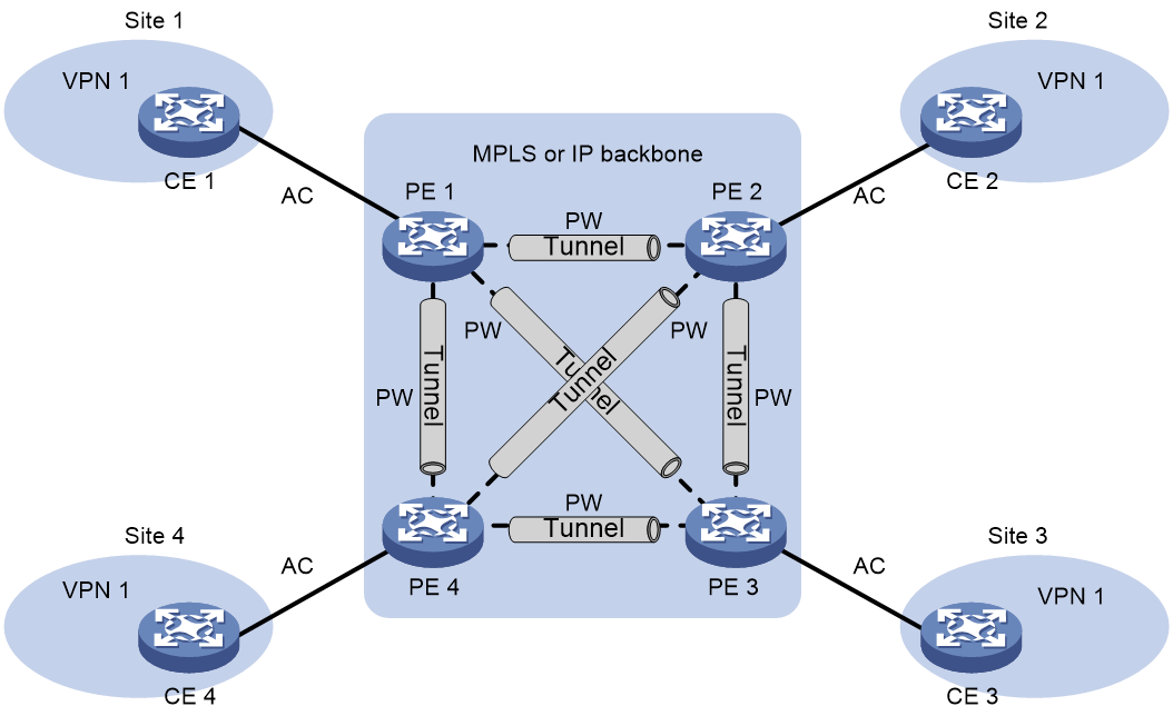
As shown in Figure 1, the VPLS architecture mainly includes the following components:
· CE—A customer edge device is directly connected to the service provider network.
· PE—A provider edge device connects one or more CEs to the service provider network. A PE implements VPN access by mapping and forwarding packets between private networks and public network tunnels. A PE can be a UPE or NPE in a hierarchical VPLS.
· AC—An attachment circuit, physical or virtual, connects a CE and a PE, such as an Ethernet link or a VLAN.
· PW—A pseudowire is a bidirectional virtual connection between two PEs. An MPLS PW consists of two unidirectional MPLS LSPs in opposite directions.
· Tunnel—A tunnel can be an LSP tunnel, an MPLS TE tunnel, or a GRE tunnel. It carries one or more PWs over an IP/MPLS backbone. If a PW is carried on an LSP or MPLS TE tunnel, each packet on the PW contains two labels. The inner label is the PW label, which identifies the PW and ensures that the packet is forwarded to the correct VSI. The outer label is the public LSP or MPLS TE tunnel label, which ensures that the packet is correctly forwarded to the remote PE.
· VPLS instance—A customer network might contain multiple geographically dispersed sites (such as site 1 and site 3 in Figure 1.) The service provider uses VPLS to connect all the sites to create a single Layer 2 VPN, which is referred to as a VPLS instance. Sites in different VPLS instances cannot communicate with each other at Layer 2.
· VSI—A virtual switch instance provides Layer 2 switching services for a VPLS instance on a PE. A VSI acts as a virtual switch that has all the functions of a conventional Ethernet switch, including source MAC address learning, MAC address aging, and flooding. VPLS uses VSIs to forward Layer 2 data packets in VPLS instances.
Creating a PW
In a VPLS network, PEs use PWs to forward packets among VPN sites.
A PW is created as follow:
1. Specify the address of the remote PE or configure an auto-discovery protocol to automatically find the remote PE. BGP is the most commonly used auto-discovery protocol.
2. Specify the incoming label and the outgoing label for the PW on the two PEs to create the PW. You can also use LDP or BGP to advertise the PW-label binding to the remote PE to establish the unidirectional LSPs. The PW is created once the two unidirectional LSPs are created.
PW types
PEs use PWs to forward packets among VPN sites. PWs include static PWs, LDP PWs, BGP PWs, and BGP auto-discovery LDP PWs.
Static PW
To create a static PW, specify the address of the remote PE, the incoming label, and the outgoing label.
LDP PW
To create an LDP PW, specify the address of the remote PE, and use LDP to advertise the PW-label binding to the remote PE. After the two PEs receive the PW-label binding from each other, they establish an LDP PW. The FEC type in the LDP message is PWid FEC Element that includes the PW ID field (FEC 128). The PW ID identifies the PW bound to the PW label.
BGP PW
To create a BGP PW, configure BGP to advertise label block information to the remote PE. After the two PEs receive label block information from each other, they use the label block information to calculate the incoming and outgoing labels and create the BGP PW. A PE also uses the received label block information to automatically find the remote PE.
BGP auto-discovery LDP PW
To create a BGP auto-discovery LDP PW, configure BGP to automatically find the remote PE, and use LDP to advertise the PW-label binding to the remote PE. After the two PEs receive the PW-label binding from each other, they establish a BGP auto-discovery LDP PW.
The information advertised by BGP includes the ID (for example, LSR ID) and VPLS ID of the advertising PE. The receiving PE compares the received VPLS ID with its own VPLS ID. If the two VPLS IDs are identical, the two PEs use LDP to establish a PW. If not, the PEs do not establish a PW. The FEC type in the LDP message is Generalized PWid FEC Element (FEC 129), which contains the VPLS ID, Source Attachment Individual Identifier (SAII), and Target Attachment Individual Identifier (TAII). The SAII is the LSR ID of the advertising PE. The TAII identifies the remote PE and is advertised by the remote PE. VPLS ID+SAII+TAII uniquely identifies a PW in a VPLS instance.
MAC address learning, aging, and withdrawal
Source MAC address learning
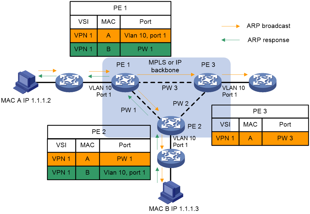
VPLS provides reachability through source MAC learning. A PE maintains a MAC address table for each VSI.
As shown in Figure 2, a PE learns source MAC addresses in the following ways:
· Learning the source MAC addresses of directly connected sites.
If the source MAC address of a packet from a CE does not exist in the MAC address table, the PE learns the source MAC address of the AC connected to the CE.
· Learning the source MAC addresses of remote sites connected through PWs.
A VSI regards a PW as a logical Ethernet interface. If the source MAC address of a packet from a PW does not exist in the MAC address table, the PE learns the source MAC address on the PW of the VSI.
Figure 2 Source MAC address learning on a PE
MAC address aging
The MAC address table uses an aging timer for each dynamic MAC address entry. If no packet is received from a MAC address before the aging timer expires, VPLS deletes the MAC address.
MAC address withdrawal
When an AC or a PW goes down, the PE deletes MAC addresses on the AC or PW. Then it sends an LDP address withdrawal message to notify all other PEs in the VPLS instance to delete those MAC addresses.
Traffic forwarding and flooding
Unicast traffic forwarding and flooding
After a PE receives a unicast packet from an AC, the PE searches the MAC address table of the VSI bound to the AC for packet forwarding.
· If a match is found, the PE forwards the packet according to the matching entry.
¡ If the outgoing interface in the entry is a PW, the PE inserts the PW label to the packet, and adds the public tunnel header to the packet. It then forwards the packet to the remote PE over the PW. If the PW is carried on an LSP or MPLS TE tunnel, each packet on the PW contains two labels. The inner label is the PW label, which identifies the PW and ensures that the packet is forwarded to the correct VSI. The outer label is the public LSP or MPLS TE tunnel label, which ensures that the packet is correctly forwarded to the remote PE.
¡ If the outgoing interface in the entry is a local interface, the PE directly forwards the packet to the local interface.
· If no match is found, the PE floods the packet to all other ACs and PWs in the VSI.
After a PE receives a unicast packet from a PW, the PE searches the MAC address table of the VSI bound to the PW for packet forwarding.
· If a match is found, the PE forwards the packet through the outgoing interface in the matching entry.
· If no match is found, the PE floods the packet to all ACs in the VSI.
Multicast and broadcast traffic forwarding and flooding
After a PE receives a multicast or broadcast packet from an AC, the PE floods the packet to all other ACs and the PWs in the VSI bound to the AC.
After a PE receives a multicast or broadcast packet from a PW, the PE floods the packet to all ACs in the VSI bound to the PW.
PW full mesh and split horizon
A Layer 2 network requires a loop prevention protocol such as STP to avoid loops. However, a loop prevention protocol on PEs brings management and maintenance difficulties. Therefore, VPLS uses the following methods to prevent loops:
· Full mesh—Every two PEs in a VPLS instance must establish a PW. The PWs form a full mesh among PEs in the VPLS instance.
· Split horizon—A PE does not forward packets received from a PW to any other PWs in the same VSI but only forwards those packets to ACs.
Flow label
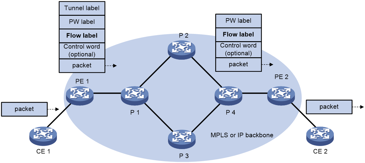
Packets carrying different types of traffic might be transmitted through the same PW and encapsulated with the same PW label. The P devices forward the traffic flows of a PW over the same path even if Equal Cost Multiple Paths (ECMPs) exist.
The L2VPN flow label feature can enable a P device to perform load sharing on packets based on the flow types.
After you configure this feature, the P and PE devices process packets as follows:
· When the ingress PE encapsulates a packet, it adds a flow label before it adds a PW label, as shown in Figure 3.
The ingress PE adds different flow labels for packets of different traffic types.
· The P devices perform load sharing on packets based on the flow labels.
· The egress PE removes both the PW and flow labels from a packet before forwarding the packet.
Figure 3 L2VPN flow label feature
You can enable the flow label sending, receiving, or both sending and receiving capabilities on a PE.
· The sending capability enables a PE to send packets with flow labels. The PE adds a flow label before it adds a PW label to a packet during PW encapsulation.
· The receiving capability enables a PE to identify the flow label in a received packet and removes the flow label before forwarding the packet.
For two PE to successfully negotiate the flow label capabilities, make sure one end has the sending capability and the other end has the receiving capability.
For static PWs, you must manually configure flow label capabilities for the local and remote PEs. For dynamic PWs, you can configure the local and remote PEs to negotiate the flow label capabilities or manually configure flow label capabilities for the PEs.
PW redundancy
PW redundancy provides redundant links between PEs so that the customer networks can communicate when the path over one PW fails. As shown in Figure 4, PE 1 establishes two PWs (one primary and one backup). The CEs communicate through the primary PW. When the primary PW fails, PE 1 brings up the backup PW and forwards packets from CE 1 to CE 2 through the backup PW. When CE 2 receives the packets, it updates its MAC address table, so that packets from CE 2 to CE 1 also travel through the backup PW. Only static PWs and LDP PWs support PW redundancy.
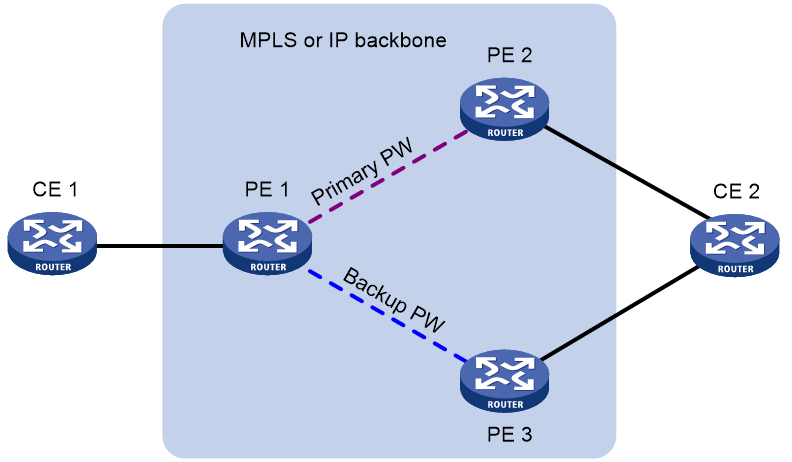
VPLS determines whether the primary PW fails according to the LDP session status or the BFD result. The backup PW is used when one of the following conditions exists:
· The public tunnel of the primary PW is deleted, or BFD detects that the public tunnel has failed.
· The primary PW is deleted because the LDP session between PEs goes down, or BFD detects that the primary PW has failed.
· A manual PW switchover is performed.
A PW can be in either of the following states:
· Active—The PW is in active state and can forward packets.
· Standby—The PW is in standby state and cannot forward packets.
LDP PWs support the independent and master/slave PW redundancy operation modes.
· Independent mode—The two PEs of a PW use LDP to advertise their respective PW active/standby state to each other. A PW can forward traffic only when it is up and active at both ends of the PW. In this mode, make sure both PEs of a PW use the independent PW redundancy operation mode.
· Master/slave mode—One PE of a PW operates as the master node and the other PE operates as the slave node. The master PE determines the PW active/standby state and then uses LDP to advertise the PW state to the slave PE. The slave PE uses the same PW state as the master PE based on the information received from the master PE. In this way, the master and slave PEs for the set of redundant PWs can use the same active PW to forward user packets.
A slave node does not advertise the PW active/standby state to the master node, and the master node ignores the PW active/standby state received from the slave nodes.
H-VPLS
About H-VPLS
VPLS requires a full mesh of PWs among all PEs in a VPLS instance. In a large-scale network, however, a full mesh of PWs causes very high PW signaling overhead and brings difficulties for network management and expansion. Hierarchical VPLS (H-VPLS) reduces the number of PWs by dividing a VPLS network into a backbone domain and edge domains.
Only static PWs and LDP PWs support H-VPLS.
In H-VPLS:
· An edge domain provides access for a user network to the backbone domain.
· The Network Provider Edge (NPE) devices are fully meshed in the backbone domain. A PW between NPEs is referred to as an N-PW.
· A User facing-Provider Edge (UPE) device only establishes a PW with the neighboring NPE. A PW between a UPE and an NPE is referred to as a U-PW.
H-VPLS access modes
H-VPLS supports the following access modes:
· MPLS access mode
As shown in Figure 5, the edge domain is an MPLS network. The UPE creates a U-PW with NPE 1. The UPE does not create PWs to any remote PEs. After receiving a packet from a CE, the UPE adds the label assigned to the U-PW into the packet and forwards the packet to NPE 1 through a public tunnel. NPE 1 maps the packet to the VSI that corresponds to the PW label, and searches the MAC address table of the VSI to forward the packet.
Figure 5 H-VPLS using MPLS access

|
|
NOTE: A U-PW created on the NPE must have split horizon disabled because the NPE needs to forward packets between U-PW and N-PW. |
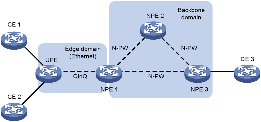
· Ethernet access mode
As shown in Figure 6, the edge domain is an Ethernet network. The UPE and NPE 1 establish a point-to-point Ethernet QinQ connection in between. After the UPE receives a packet from a CE, it adds an outer VLAN tag into the packet and forwards the packet to NPE 1. NPE 1 regards the outer VLAN tag as the service provider VLAN tag. It maps the packet to the VSI that corresponds to the VLAN tag and then searches the MAC address table of the VSI to forward the packet.
Figure 6 H-VPLS using Ethernet access
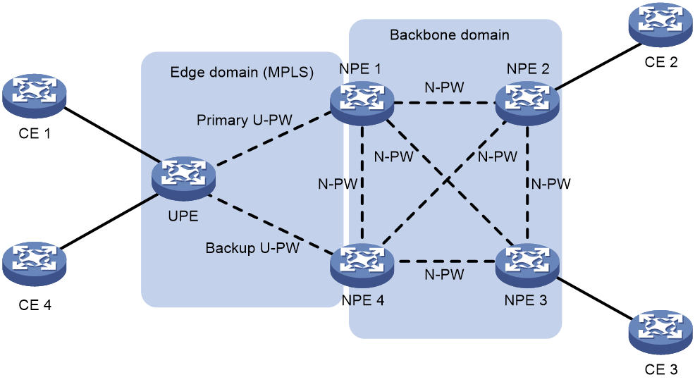
UPE dual homing and PW redundancy
To provide U-PW redundancy for a UPE, you can connect the UPE to two NPEs. Even if a U-PW fails, all customer sites connected to the UPE maintain the connectivity.
In the H-VPLS using MPLS access as shown in Figure 7, the UPE is connected to two NPEs through primary and backup U-PWs. The UPE uses the primary U-PW to forward traffic. When the primary U-PW fails, the UPE uses the backup U-PW to forward traffic.
Figure 7 UPE dual homing and redundancy in H-VPLS using MPLS access
Hub-spoke networking
The hub-spoke network model has one hub site and multiple spoke sites. The spoke sites cannot directly communicate with each other. Traffic between spoke sites must travel through the hub site, so the hub site can implement centralized traffic management.
Only static PWs and LDP PWs support the hub-spoke network model.
Figure 8 Hub-spoke model of VPLS
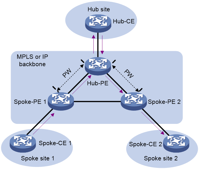
As shown in Figure 8:
· The CE in the hub site is called a hub-CE.
· The PE connected to the hub site is called a hub-PE.
· A CE in a spoke site is called a spoke-CE.
· A PE connected to a spoke site is called a spoke-PE.
· A link (AC or PW) towards the hub site is called a hub link. You must specify one and only one hub link in a VSI.
· A link (AC or PW) towards a spoke site is called a spoke link.
In the hub-spoke VPLS network, a PE performs MAC address learning and forwarding as follows:
· After receiving a packet from a spoke link, the PE performs MAC address learning and forwards the packet to the hub link.
· After receiving a packet from the hub link, the PE does not learn the MAC address. Instead, it searches the MAC address table to forward the packet to a spoke link.
E-Tree networking
About E-Tree
In a VPLS network, ACs can communicate whether they are connected to the same PE or to different PEs. To improve security and isolate ACs, enable E-Tree on the PEs. Then, communication is allowed only between root links and between root and leaf links. Leafs cannot communicate with each other.
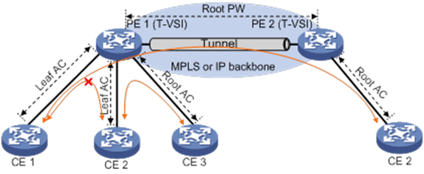
As shown in Figure 9, in a VPLS E-Tree network, a T-VSI is a VSI supporting E-Tree. A PE and its connected CEs form a local E-Tree network. Multiple PEs and their connected CEs form a remote E-Tree network. A link (AC or PW) is designated as either root or leaf. A leaf VLAN is used to identify leaf PWs and a root VLAN is used to identify root PWs.
A PE can forward packets from a leaf AC to only root links and forward packets from a root AC to both leaf and root links.
A PE can forward packets from a leaf PW to only local root ACs and forward packets from a root PW to both leaf and root ACs. A PE identifies the role of a PW based on the VLAN ID in the packets received from the PW. If the VLAN ID is the same as the locally configured root VLAN ID, the PW is a root PW. If the VLAN ID is the same as the locally configured leaf VLAN ID, the PW is a leaf PW.
PW E-Tree mode
The following PW E-Tree modes are available:
· Compatible—This mode is applicable when only the local PE supports E-Tree. The local PE does not modify the VLAN IDs in packets sent to or received from the remote PE. It forwards packets received from the remote PE based on the MAC address table of the VSI to which the PW belongs.
To forward packets from only the root ACs to the remote PE (E-Tree unsupported), you can specify this mode on the local PE and then configure the PW as a leaf PW. This can also save the PW bandwidth.
· Optimized—This mode is applicable when both the local and remote PEs support E-Tree and all ACs connected to the remote PE are leaf ACs.
¡ Before forwarding a packet from an AC to the remote PE, the local PE checks the role of the AC. If the packet comes from a leaf AC, the PE discards the packet. If the packet comes from a root AC, the PE replaces the VLAN ID in the packet with the local root VLAN ID and then forwards the packet.
¡ After receiving a packet from the remote PE, the local PE does not replace the VLAN ID in the packet with the local root or leaf VLAN ID. It forwards the packet based on the MAC address table of the VSI to which the PW belongs.
· VLAN mapping—This mode is applicable when the local and remote PEs of a PW use different root or leaf VLAN IDs.
¡ Before forwarding a packet to the remote PE, the local PE replaces the VLAN ID in the packet with the local root or leaf VLAN ID.
¡ After receiving a packet from the remote PE, the local PE maps the VLAN ID in the packet to the local root or leaf VLAN ID and then forwards the packet.
Interconnecting an EVPN VXLAN network with a VPLS network
This task applies to the following scenarios:
· A newly deployed EVPN VXLAN network in one data center needs to communicate with an existing VPLS network in another data center.
· Two data centers with EVPN VXLAN networks deployed need to communicate over a WAN VPLS network.
As shown in Figure 10, for an EVPN VXLAN network and a VPLS network to communicate over a WAN VPLS network, configure the intermediate border devices GW 1 and GW 2 as follows:
· Configure EVPN VXLAN and VPLS.
· Interconnect the EVPN VXLAN network with the VPLS network by mapping the LDP PWs or static PWs on the VPLS network to the VXLAN tunnels.
On the intermediate border devices, the LDP PWs or static PWs of VPLS act as ACs of EVPN VXLAN. These PWs are called UPWs. The intermediate border devices can forward traffic between the VXLAN tunnels and the UPWs to enable communication between the EVPN VXLAN network and the VPLS network.
Figure 10 Interconnection between an EVPN VXLAN network and a VPLS network
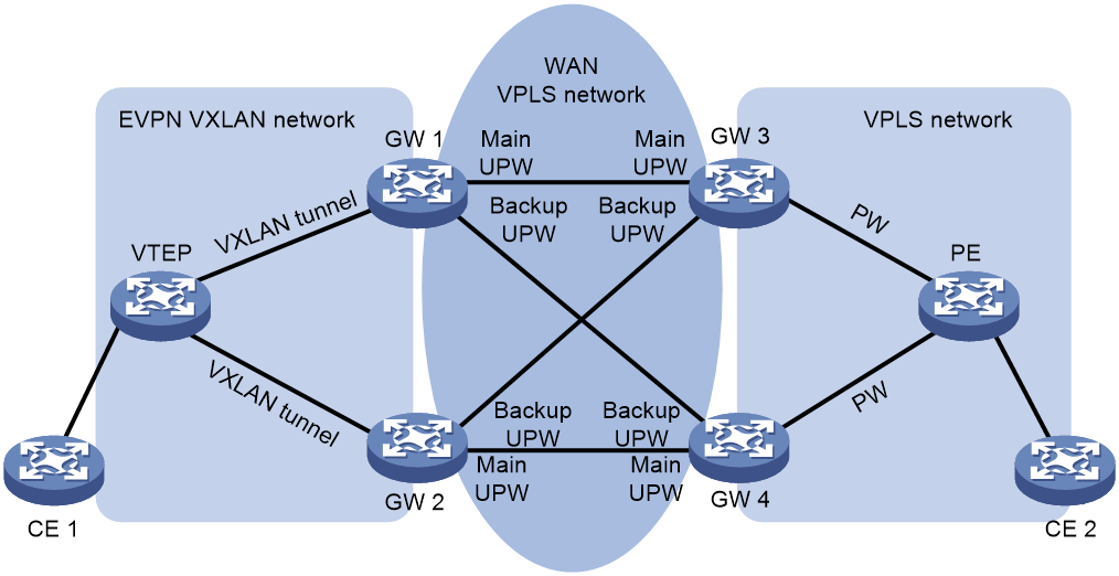
As shown in Figure 10, the VTEP sets up VXLAN tunnels with GW 1 and GW 2, the gateways set up UPWs over the WAN VPLS network as follows:
· GW 1 sets up a main UPW and a backup UPW with GW 3 and GW 4, respectively.
· GW 2 sets up a main UPW and a backup UPW with GW 4 and GW 3, respectively.
When GW 1 or GW 2 receives a packet from a UPW, the gateway performs the following actions:
1. Removes the MPLS encapsulation.
2. Looks up the MAC address table for an outgoing VXLAN tunnel interface.
3. Adds VXLAN encapsulation to the packet.
4. Forwards the packet to the VTEP over the matching VXLAN tunnel.
When receiving a packet from a VXLAN tunnel, GW 1 or GW 2 uses a similar workflow to forward the packet over a UPW to the VPLS network.
For more information about interconnecting an EVPN VXLAN network with a VPLS network, see EVPN VXLAN configuration in EVPN Configuration Guide.
VPLS tasks at a glance
Perform the following configuration tasks on a PE:
Choose the following tasks as needed:
¡ (Optional.) Configuring a PW class
¡ Configuring a BGP auto-discovery LDP PW
¡ (Optional.) Configuring the BGP L2VPN address family
You can configure this task to control route advertisement and selection in BGP L2VPN address family when you configure a BGP PW or BGP auto-discovery LDP PW.
¡ (Optional.) Maintaining BGP sessions
If BGP configuration is changed, you can reset or soft-reset BGP sessions to validate the new configuration for BGP PWs and BGP auto-discovery LDP PWs.
In an H-VPLS using MPLS access, this task is not needed on the access NPEs of the UPEs.
6. (Optional.) Configuring PW redundancy
7. (Optional.) Configuring E-Tree
8. (Optional.) Configuring MAC address learning for a VSI
9. (Optional.) Setting the maximum number of MAC addresses that an AC and a PW can learn
10. (Optional.) Enabling VPLS statistics
11. (Optional.) Enabling bandwidth-based load sharing
12. (Optional.) Maintaining the VPLS network:
¡ Enabling SNMP notifications for L2VPN PW
Prerequisites for VPLS
To configure a VPLS network, perform the following tasks:
· Configure an IGP to ensure IP connectivity within the backbone.
· Configure basic MPLS, LDP, GRE, or MPLS TE to establish public tunnels on the backbone network.
If the public tunnel is a GRE tunnel, perform the following tasks:
· Configure an LSR ID for the PE by using the mpls lsr-id command.
· Enable MPLS with the mpls enable command on the backbone interface of the PE.
For more information about the mpls lsr-id and mpls enable commands, see MPLS Command Reference.
Enabling L2VPN
1. Enter system view.
system-view
2. Enable L2VPN.
l2vpn enable
By default, L2VPN is disabled.
Configuring an AC
Configuring a Layer 3 interface
When the PE is connected to a CE through a Layer 3 interface, you must configure the Layer 3 interface to establish an AC to the CE.
The Layer 3 interface can be a Layer 3 Ethernet interface (including physical Layer 3 Ethernet interface and VE-L2VPN interface) or Layer 3 Ethernet subinterface.
For more information about Ethernet interfaces, see Interface Configuration Guide. For more information about VE-L2VPN interfaces, see "Configuring L2VPN access to L3VPN or IP backbone."
Configuring an Ethernet service instance
About this task
When the PE is connected to a CE through a Layer 2 Ethernet or Layer 2 aggregate interface, configure an Ethernet service instance on the interface to match packets from the AC. The Ethernet service instance provides flexible methods for matching packets to be forwarded in the VSI.
Restrictions and guidelines
You cannot repeat the encapsulation command to modify the packet match criterion of an Ethernet service instance. To change the packet match criterion, first execute the undo encapsulation command to remove the original match criterion.
If the packet match criterion of an Ethernet service instance is removed, the binding between the Ethernet service instance and the VSI is removed automatically.
Procedure
1. Enter system view.
system-view
2. Enter interface view.
¡ Enter Layer 2 Ethernet interface view.
interface interface-type interface-number
¡ Enter Layer 2 aggregate interface view.
interface bridge-aggregation interface-number
3. Create an Ethernet service instance and enter Ethernet service instance view.
service-instance instance-id
4. Configure a packet match criterion for the Ethernet service instance.
¡ Match packets with the specified outer VLAN IDs.
encapsulation s-vid vlan-id-list
¡ Match packets with the specified outer VLAN IDs and inner VLAN IDs.
encapsulation s-vid vlan-id c-vid vlan-id-list
By default, no packet match criterion is configured.
(Optional) Configuring a VLAN tag processing rule for incoming packets
Restrictions and guidelines
In standard system operating mode, this feature is available only for the following cards:
|
Card category |
Cards |
|
CEPC |
CEPC-CQ8L, CEPC-CQ8LA, CEPC-CQ8L1A, CEPC-CQ16L1 |
|
CSPEX |
CSPEX-1802X, CSPEX-1802XA, CSPEX-2612XA, CSPEX-1812X-E, CSPEX-2304X-G, CSPEX-1502XA |
|
SPE |
RX-SPE200-E |
In SDN-WAN system operating mode, this feature is available only for the following cards:
|
Card category |
Cards |
|
CEPC |
CEPC-XP4LX, CEPC-XP24LX, CEPC-XP48RX, CEPC-CP4RX, CEPC-CP4RXA, CEPC-CP4RX-L, CEPC-CQ8L, CEPC-CQ8LA, CEPC-CQ8L1A, CEPC-CQ16L1 |
|
CSPEX |
CSPEX-1304X, CSPEX-1404X, CSPEX-1502X, CSPEX-1504X, CSPEX-1504XA, CSPEX-1602X, CSPEX-1602XA, CSPEX-1804X, CSPEX-1512X, CSPEX-1612X, CSPEX-1812X, CSPEX-1802X, CSPEX-1802XA, CSPEX-2612XA, CSPEX-1812X-E, CSPEX-2304X-G, CSPEX-1502XA |
|
SPE |
RX-SPE200, RX-SPE200-E |
Only ACs that use the Ethernet access mode support this feature.
Configure this feature before you associate the AC with VSI.
To delete the VLAN tag processing rule for incoming packets by using the undo rewrite inbound tag command, you must first disassociate the AC from VSI by using the undo xconnect vsi command.
To edit the VLAN tag processing rule for incoming packets, you must first delete the rule by using the undo rewrite inbound tag command, and then execute the rewrite inbound tag command to configure the rule again.
This feature is mutually exclusive with the vlan-type dot1q vid vlan-id-list second-dot1q any command on a Layer 3 subinterface. For more information about the vlan-type dot1q vid second-dot1q command, see VLAN termination commands in Layer 2—LAN Switching Command Reference.
After you configure this feature on an Ethernet service instance, the Layer 2 Ethernet interface or Layer 2 aggregate interface to which the Ethernet service instance belongs does not support the qinq enable command. For more information about the qinq enable command, see QinQ commands in Layer 2—LAN Switching Command Reference.
This feature is not available for CFD or NQA.
Procedure
1. Enter system view.
system-view
2. Enter interface view.
¡ Enter Layer 3 interface view.
interface interface-type interface-number
¡ Enter Layer 3 subinterface view.
interface interface-type interface-number.subnumber
¡ Enter Ethernet service instance view.
interface interface-type interface-number
service-instance instance-id
3. Configure a VLAN tag processing rule for incoming packets.
rewrite inbound tag { nest s-vid vlan-id [ c-vid vlan-id ] | remark { { 1-to-1 | 2-to-1 } s-vid vlan-id | { 1-to-2 | 2-to-2 } s-vid vlan-id c-vid vlan-id | offset { decrease offset-vid | increase offset-vid } } | strip s-vid [ c-vid ] | swap } [ symmetric ]
Configuring a VSI
1. Enter system view.
system-view
2. Create a VSI and enter VSI view.
vsi vsi-name [ hub-spoke ]
If you specify the hub-spoke keyword for a VSI, the VSI supports the hub-spoke network model.
3. (Optional.) Configure a description for the VSI.
description text
By default, no description is configured for a VSI.
4. (Optional.) Set the default PW ID for the VSI.
default-pw-id default-pw-id
By default, no default PW ID is configured for the VSI.
5. Set an MTU for the VSI.
mtu size
By default, the MTU of a VSI is 1500 bytes.
6. Set the broadcast, multicast, or unknown unicast suppression bandwidth.
restrain { broadcast | multicast | unknown-unicast } bandwidth
By default, the broadcast, multicast, and unknown unicast suppression bandwidth is 5120 kbps.
7. (Optional.) Enable the VSI.
undo shutdown
By default, a VSI is enabled.
Configuring a PW
Configuring a PW class
About this task
In a PW class, you can configure PW attributes such as the PW data encapsulation type, and whether to enable control word. To simplify PW configuration, you can configure PWs with the same attributes by referencing the same PW class.
Procedure
1. Enter system view.
system-view
2. Create a PW class and enter PW class view.
pw-class class-name
By default, no PW classes exist.
3. (Optional.) Enable control word.
control-word enable
By default, control word is disabled.
4. (Optional.) Specify the PW data encapsulation type.
pw-type { ethernet | vlan } [ force-for-vpls ]
By default, the PW data encapsulation type is VLAN.
5. (Optional.) Enable the flow label feature and configure flow label capabilities.
flow-label { both | receive | send } [ static ]
By default, the flow label feature is disabled.
For the flow label feature to take effect, you need to configure the mpls load-sharing mode command on the P devices. For more information about the mpls load-sharing mode command, see basic MPLS commands in MPLS Command Reference.
Configuring a static PW
1. Enter system view.
system-view
2. Enter VSI view.
vsi vsi-name [ hub-spoke ]
3. Specify static signaling for PWs, and enter VSI static view.
pwsignaling static
By default, no PW signaling protocol is specified.
4. Configure a static PW, and enter VSI static PW view.
peer ip-address [ pw-id pw-id ] in-label label-value out-label label-value [ dci | hub | no-split-horizon | pw-class class-name | tunnel-policy tunnel-policy-name ] *
|
Parameter |
Description |
|
pw-id pw-id |
If both the default PW ID in the default-pw-id command and a PW ID in the peer command are configured, the PW ID in the peer command is used. If only the default PW ID is configured, the default PW ID is used. If no default PW ID is configured, you must provide a PW ID in the peer command. |
|
dci |
Specify this keyword to establish a DCI PW between EDs in a DCI network. DCI PWs use split horizon for packet forwarding to avoid loops. If you do not specify this keyword, the PW is established within the data center. |
|
hub |
If a VSI is enabled with the hub-spoke capability (the hub-spoke keyword in the vsi command), PWs in the VSI are spoke links by default. You can use the hub keyword in this command to specify the static PW as the hub link in the VSI. |
|
no-split-horizon |
You must specify the no-split-horizon keyword to disable split horizon when you configure an NPE to establish a U-PW with a UPE. |
5. (Optional.) Bind the static PW to an administration PW.
binding admin-pw interface interface-type interface-number
By default, a static PW is not bound to an administration PW.
Configuring an LDP PW
Prerequisites
Before you configure an LDP PW, enable global and interface MPLS LDP on the PE. For information about MPLS LDP configuration, see "Configuring LDP."
Procedure
1. Enter system view.
system-view
2. Enter VSI view.
vsi vsi-name [ hub-spoke ]
3. Specify LDP signaling for PWs, and enter VSI LDP signaling view.
pwsignaling ldp
By default, no PW signaling protocol is specified.
4. (Optional.) Disable PW MTU negotiation.
mtu-negotiate disable
By default, PW MTU negotiation is enabled.
Execute this command if you want to establish a PW between two PEs that are configured with different PW MTUs.
5. Configure an LDP PW, and enter VSI LDP PW view.
peer ip-address [ pw-id pw-id ] [ dci | hub | ignore-standby-state | no-split-horizon | pw-class class-name | tunnel-policy tunnel-policy-name ] *
|
Parameter |
Description |
|
pw-id pw-id |
If both the default PW ID in the default-pw-id command and a PW ID in the peer command are configured, the PW ID in the peer command is used. If only the default PW ID is configured, the default PW ID is used. If no default PW ID is configured, you must provide a PW ID in the peer command. |
|
dci |
Specify this keyword to establish a DCI PW between EDs in a DCI network. DCI PWs use split horizon for packet forwarding to avoid loops. If you do not specify this keyword, the PW is established within the data center. |
|
hub |
If a VSI is enabled with the hub-spoke capability (the hub-spoke keyword in the vsi command), PWs in the VSI are spoke links by default. You can use the hub keyword in this command to specify the static PW as the hub link in the VSI. |
|
no-split-horizon |
You must specify the no-split-horizon keyword to disable split horizon when you configure an NPE to establish a U-PW with a UPE. |
6. (Optional.) Bind the LDP PW to an administration PW.
binding admin-pw interface interface-type interface-number
By default, an LDP PW is not bound to an administration PW.
Configuring a BGP PW
Configuring BGP to advertise VPLS label block information
1. Enter system view.
system-view
2. Enable BGP instance and enter BGP instance view.
bgp as-number [ instance instance-name ]
By default, BGP is disabled.
For more information about this command, see BGP in Layer 3—IP Routing Command Reference.
3. Configure the remote PE as a BGP peer.
peer { group-name | ip-address [ mask-length ] } as-number as-number
For more information about this command, see BGP in Layer 3—IP Routing Command Reference.
4. Create the BGP L2VPN address family and enter BGP L2VPN address family view.
address-family l2vpn
5. Enable BGP to exchange L2VPN information with the specified peer or peer group.
peer { group-name | ip-address [ mask-length ] } enable
By default, BGP cannot exchange L2VPN information with any peer or peer group.
For more information about this command, see BGP in Layer 3—IP Routing Command Reference.
6. Enable BGP to exchange label block information with the specified peer or peer group.
peer { group-name | ip-address [ mask-length ] } signaling
By default, BGP can exchange label block information with a BGP L2VPN peer or peer group.
7. (Optional.) Configure the BGP L2VPN address family.
For more information, see "Configuring the BGP L2VPN address family."
8. (Optional.) Maintain BGP sessions.
For more information, see "Maintaining BGP sessions."
Creating a BGP PW
1. Enter system view.
system-view
2. Enter VSI view.
vsi vsi-name [ hub-spoke ]
3. Configure the VSI to automatically discover neighbors through BGP and enter auto-discovery VSI view.
auto-discovery bgp
By default, a VSI does not automatically discover neighbors through BGP.
4. Configure an RD for the auto-discovery VSI.
route-distinguisher route-distinguisher
By default, no RD is configured for the auto-discovery VSI.
5. Configure route targets for the auto-discovery VSI.
vpn-target vpn-target&<1-8> [ both | export-extcommunity | import-extcommunity ]
By default, no route targets are configured for the auto-discovery VSI.
6. (Optional.) Specify a PW class for the auto-discovery VSI.
pw-class class-name
By default, no PW class is specified.
7. (Optional.) Specify a tunnel policy for the auto-discovery VSI.
tunnel-policy tunnel-policy-name
By default, no tunnel policy is specified.
8. Use BGP to create a PW to an automatically discovered remote PE and enter auto-discovery VSI BGP signaling view.
signaling-protocol bgp
By default, no signaling protocol is specified.
9. Create a local site.
site site-id [ range range-value ] [ default-offset default-offset ]
Configuring a BGP auto-discovery LDP PW
Prerequisites for configuring a BGP auto-discovery LDP PW
Before you perform this configuration, enable MPLS LDP on interfaces and globally. For more information, see "Configuring LDP."
Configuring BGP to advertise VPLS PE information
1. Enter system view.
system-view
2. Enable BGP instance and enter BGP instance view.
bgp as-number [ instance instance-name ]
By default, BGP is disabled.
For more information about this command, see BGP in Layer 3—IP Routing Command Reference.
3. Configure the remote PE as a BGP peer.
peer { group-name | ip-address [ mask-length ] } as-number as-number
For more information about this command, see BGP in Layer 3—IP Routing Command Reference.
4. Create the BGP L2VPN address family and enter BGP L2VPN address family view.
address-family l2vpn
5. Enable BGP to exchange VPLS PE information with the specified peer or peer group.
peer { group-name | ip-address [ mask-length ] } enable
By default, BGP cannot exchange VPLS PE information with a peer or peer group.
For more information about this command, see BGP in Layer 3—IP Routing Command Reference.
6. Enable BGP to exchange VPLS PE information with the specified peer or peer group.
peer { group-name | ip-address [ mask-length ] } auto-discovery [ non-standard ]
By default, BGP can exchange VPLS PE information with a BGP L2VPN peer or peer group by using RFC 6074 MP_REACH_NLRI.
7. (Optional.) Configure the BGP L2VPN address family.
For more information, see "Configuring the BGP L2VPN address family."
8. (Optional.) Maintain BGP sessions.
For more information, see "Maintaining BGP sessions."
Creating a BGP auto-discovery LDP PW
1. Enter system view.
system-view
2. Enter VSI view.
vsi vsi-name [ hub-spoke ]
3. Configure the VSI to automatically discover neighbors through BGP and enter auto-discovery VSI view.
auto-discovery bgp
By default, a VSI does not automatically discover neighbors through BGP.
4. Configure an RD for the auto-discovery VSI.
route-distinguisher route-distinguisher
By default, no RD is configured for the auto-discovery VSI.
5. Configure route targets for the auto-discovery VSI.
vpn-target vpn-target&<1-8> [ both | export-extcommunity | import-extcommunity ]
By default, no route targets are configured for the auto-discovery VSI.
6. (Optional.) Specify a PW class for the auto-discovery VSI.
pw-class class-name
By default, no PW class is specified.
7. (Optional.) Specify a tunnel policy for the auto-discovery VSI.
tunnel-policy tunnel-policy-name
By default, no tunnel policy is specified.
8. Use LDP to create a PW to an automatically discovered remote PE and enter auto-discovery VSI LDP signaling view.
signaling-protocol ldp
By default, no signaling protocol is specified.
9. Configure a VPLS ID for the VSI.
vpls-id vpls-id
By default, no VPLS ID is configured.
Configuring the BGP L2VPN address family
About this task
When you configure a BGP PW or a BGP auto-discovery LDP PW, you can perform this task to control route advertisement and selection in the BGP L2VPN address family.
Procedure
1. Enter system view.
system-view
2. Enter BGP instance view.
bgp as-number [ instance instance-name ]
3. Enter BGP L2VPN address family view.
address-family l2vpn
4. (Optional.) Set the maximum number of routes that can be received from the specified peer or peer group.
peer { group-name | ipv4-address [ mask-length ] } route-limit prefix-number [ { alert-only | discard | reconnect reconnect-time } | percentage-value ] *
By default, no limit is set for the number of routes that can be received from a peer or peer group.
5. Permit the local AS number to appear in routes from the specified peer or peer group and specify the maximum number of the appearances.
peer { group-name | ip-address [ mask-length ] } allow-as-loop [ number ]
By default, the local AS number is not allowed in routes from a peer or peer group.
6. Enable route target-based filtering of incoming BGP L2VPN information.
policy vpn-target
By default, route target-based filtering of incoming BGP L2VPN information is enabled.
7. Configure BGP route reflection.
¡ Configure the device as a route reflector and specify a peer or peer group as its client.
peer { group-name | ip-address [ mask-length ] } reflect-client
By default, no route reflector or client is configured.
¡ Enable L2VPN information reflection between clients.
reflect between-clients
By default, L2VPN information reflection is enabled between clients.
¡ Configure the cluster ID of the route reflector.
reflector cluster-id { cluster-id | ip-address }
By default, a route reflector uses its own router ID as the cluster ID.
¡ Configure the route reflector to filter reflected L2VPN information.
rr-filter ext-comm-list-number
By default, a route reflector does not filter reflected L2VPN information.
8. (Optional.) Set the BGP optimal route selection delay timer.
route-select delay delay-value
By default, the BGP optimal route selection delay timer is 0 seconds, which means optimal route selection is not delayed.
For more information about this command, see BGP commands in Layer 3—IP Routing Command Reference.
Maintaining BGP sessions
About this task
If BGP configuration is changed, you can reset or soft-reset BGP sessions to validate the new configuration for BGP PWs and BGP auto-discovery LDP PWs.
A soft reset updates BGP routing information without tearing down BGP connections. A reset operation updates BGP routing information by tearing down, and then re-establishing BGP connections. Soft reset requires that BGP peers have route refresh capability (support the ROUTE-REFRESH message).
For more information about the commands in this task, see BGP in Layer 3—IP Routing Command Reference.
Procedure
To maintain BGP sessions, execute one of the following commands in user view:
· Soft-reset L2VPN BGP sessions.
refresh bgp [ instance instance-name ] { ip-address [ mask-length ] | all | external | group group-name | internal } { export | import } l2vpn
· Reset L2VPN BGP sessions.
reset bgp [ instance instance-name ] { as-number | ip-address [ mask-length ] | all | external | group group-name | internal } l2vpn
Binding an AC to a VSI
About binding an AC to a VSI
After you bind a Layer 3 interface to a VSI, packets received from the Layer 3 interface are forwarded based on the MAC address table of the VSI.
After you bind an Ethernet service instance on a Layer 2 Ethernet or Layer 2 aggregate interface to a VSI, the Ethernet service instance matches packets received on that interface. The matching packets are then forwarded based on the MAC address table of the VSI. An Ethernet service instance can match all packets, tagged packets, or untagged packets.
When you bind an AC to a VSI, you can associate Track with the AC. Then, the AC is up only when one or more of the associated track entries are positive.
Associating Track with an AC helps detecting AC failure. For example, when an AC is a VE-L2VPN interface, the interface will not go down upon a link failure because the interface is a virtual interface. To resolve the problem, you can associate Track with the AC to detect failures on the link that connects the PE-agg to the L3VPN or IP backbone. When a failure occurs on the link, the VE-L2VPN interface is set to down. Consequently, the PW bound to the AC goes down. If the PW has a backup PW, traffic can be switched to the backup PW. For more information about VE-L2VPN interfaces and L2VPN access to L3VPN or IP backbone, see "Configuring L2VPN access to L3VPN or IP backbone."
Restrictions and guidelines for binding an AC to a VSI
If a Layer 3 Ethernet interface has been added to a link aggregation group, you cannot bind the Layer 3 interface to a VSI, and vice versa.
If a Layer 2 Ethernet interface has been added to a link aggregation group, you cannot bind an Ethernet service instance on the interface to a VSI, and vice versa.
This feature is mutually exclusive with Layer 3 aggregate interface/subinterface-based traffic policing (configured by using the qos car command) as well as interface-based user profiles. For more information about user profiles, see user profile configuration in BRAS Configuration Guide.
· For the cards in the followin table, if multiple Layer 3 subinterfaces on an interface act as ACs, you must configure the same access mode for these ACs:
|
Card category |
Cards |
|
CEPC |
CSPC-GE16XP4L-E, CSPC-GE24L-E, CSPC-GP24GE8XP2L-E |
|
CSPEX |
CSPEX-1104-E, CSPEX-1204 |
· VLAN interfaces cannot associate with VSIs.
· For the cards in the following table, you must enable QinQ on an interface if you specify the Ethernet access mode when associating an Ethernet service instance on the interface with a VSI:
|
Card category |
Cards |
|
CEPC |
CSPC-GE16XP4L-E, CSPC-GE24L-E, CSPC-GP24GE8XP2L-E |
|
CSPEX |
CSPEX-1104-E, CSPEX-1204 |
· For some cards, when you associate an Ethernet service instance on an interface with a VSI:
¡ If you specify the Ethernet access mode and enable QinQ on the interface, the interface's PVID must be the same as the outer VLAN ID configured by the encapsulation command.
¡ If QinQ is not enabled on the interface, the interface's PVID must be different from the outer VLAN ID configured by the encapsulation command.
These restrictions apply to the cards in the following table:
|
Card category |
Cards |
|
CEPC |
CEPC-XP4LX, CEPC-XP24LX, CEPC-XP48RX, CEPC-CP4RX, CEPC-CP4RXA, CEPC-CP4RX-L, CEPC-CQ8L, CEPC-CQ8LA, CEPC-CQ8L1A, CEPC-CQ16L1 |
|
CSPEX |
CSPEX-1304X, CSPEX-1404X, CSPEX-1502X, CSPEX-1504X, CSPEX-1504XA, CSPEX-1602X, CSPEX-1602XA, CSPEX-1804X, CSPEX-1512X, CSPEX-1612X, CSPEX-1812X, CSPEX-1802X, CSPEX-1802XA, CSPEX-2612XA, CSPEX-1812X-E, CSPEX-2304X-G, CSPEX-1502XA |
|
SPE |
RX-SPE200, RX-SPE200-E |
Binding a Layer 3 interface to a VSI
1. Enter system view.
system-view
2. Enter Layer 3 interface view.
interface interface-type interface-number
3. Bind the interface to a VSI.
xconnect vsi vsi-name [ access-mode { ethernet | vlan } | { hub| leaf } ] * [ track track-entry-number&<1-3> ]
By default, an interface is not bound to any VSI.
|
Parameter |
Description |
|
access-mode { ethernet | vlan } |
The AC access mode determines how the device (PE) considers the VLAN tag in Ethernet frames received from the CE and how the PE forwards Ethernet frames to the CE. · VLAN access mode—Ethernet frames received from the CE must carry a VLAN tag in the Ethernet header. The PE considers the VLAN tag as a P-tag assigned by the service provider. Ethernet frames sent to the CE must also carry the P-tag. · Ethernet access mode—If Ethernet frames from the CE have a VLAN tag in the header, the PE considers it as a U-tag and ignores it. Ethernet frames sent to the CE do not carry the P-tag. |
|
hub |
If the hub-spoke capability is enabled for a VSI, an AC in the VSI is a spoke link by default. You can use the hub keyword to specify the AC as a hub link. |
|
leaf |
Specify this keyword to configure the AC as a leaf AC. In an E-Tree network, a root AC can communicate with any root or leaf AC, while a leaf AC can communicate only with a root AC. Designate an AC as a root or leaf AC as needed. By default, an AC acts as a root AC in an E-Tree network. |
Binding an Ethernet service instance to a VSI
1. Enter system view.
system-view
2. Enter interface view.
¡ Enter Layer 2 Ethernet interface view:
interface interface-type interface-number
¡ Enter Layer 2 aggregate interface view:
interface bridge-aggregation interface-number
3. Create an Ethernet service instance and enter Ethernet service instance view.
service-instance instance-id
By default, no Ethernet service instances exist.
4. Bind the Ethernet service instance to a VSI.
xconnect vsi vsi-name [ access-mode { ethernet | vlan } | { hub| leaf } ] * [ track track-entry-number&<1-3> ]
By default, an Ethernet service instance is not bound to any VSI.
If the hub-spoke capability is enabled for a VSI, an AC in the VSI is a spoke link by default. You can use the hub keyword to specify the AC as a hub link.
Configuring PW redundancy
Restrictions and guidelines for configuring PW redundancy
To use PW classs in PW redundancy, the primary and backup PWs must both use a PW class and the used PW classes must have the same configuration.
Configuring static PW redundancy
1. Enter system view.
system-view
2. Enter VSI view.
vsi vsi-name [ hub-spoke ]
3. (Optional.) Configure the dual receive feature for PW redundancy.
protection dual-receive
By default, the dual receive feature is disabled. When the primary PW is normal, the backup PW does not send or receive packets.
4. Specify static signaling for PWs, and enter VSI static view.
pwsignaling static
By default, no PW signaling protocol is specified for the VSI.
5. (Optional.) Specify the switchover mode and set the wait time for the switchover.
revertive { wtr wtr-time | never }
By default, the switchover mode is revertive and the switchover wait time is 0 seconds.
6. Configure a static PW and enter VSI static PW view.
peer ip-address [ pw-id pw-id ] [ in-label label-value out-label label-value ] [ dci | hub | no-split-horizon | pw-class class-name | tunnel-policy tunnel-policy-name ] *
7. Configure a backup static PW and enter VSI static backup PW view.
backup-peer ip-address [ pw-id pw-id ] in-label label-value out-label label-value [ pw-class class-name | tunnel-policy tunnel-policy-name ] *
If both the default PW ID in the default-pw-id command and a PW ID in the backup-peer command are configured, the PW ID in the backup-peer command is used. If only the default PW ID is configured, the default PW ID is used. If no default PW ID is configured, you must provide a PW ID in the backup-peer command.
8. (Optional.) Manually switch the traffic:
a. Return to user view.
return
b. Manually switch traffic of the PW to its backup PW.
l2vpn switchover peer ip-address pw-id pw-id
Configuring LDP PW redundancy
1. Enter system view.
system-view
2. Enter VSI view.
vsi vsi-name [ hub-spoke ]
3. (Optional.) Configure the dual receive feature for PW redundancy.
protection dual-receive
By default, the dual receive feature is disabled. When the primary PW is normal, the backup PW does not send or receive packets.
4. Specify LDP signaling for PWs, and enter VSI LDP signaling view.
pwsignaling ldp
By default, no PW signaling protocol is specified for the VSI.
5. (Optional.) Specify a PW redundancy operation mode.
pw-redundancy { independent | master }
By default, the PW redundancy operation mode is master/slave and the local PE operates as the slave node.
Do not configure this command on the local PE if the remote PE does not support the PW redundancy operation mode configuration.
6. (Optional.) Specify the switchover mode and set the wait time for the switchover.
revertive { wtr wtr-time | never }
By default, the switchover mode is revertive and the switchover wait time is 0 seconds.
7. Configure an LDP PW and enter VSI LDP PW view.
peer ip-address [ pw-id pw-id ] [ dci | hub | no-split-horizon | pw-class class-name | tunnel-policy tunnel-policy-name ] *
8. Configure a backup LDP PW and enter VSI LDP backup PW view.
backup-peer ip-address [ pw-id pw-id ] [ pw-class class-name | tunnel-policy tunnel-policy-name ] *
If both the default PW ID in the default-pw-id command and a PW ID in the backup-peer command are configured, the PW ID in the backup-peer command is used. If only the default PW ID is configured, the default PW ID is used. If no default PW ID is configured, you must provide a PW ID in the backup-peer command.
9. (Optional.) Manually switch the traffic:
a. Return to user view.
return
b. Manually switch traffic of the PW to its backup PW.
l2vpn switchover peer ip-address pw-id pw-id
Configuring E-Tree
E-Tree tasks at a glance
To configure a local E-Tree network, perform the following tasks:
To configure remote E-Tree, perform the following tasks:
· (Optional.) Configuring a PW
· Configuring remote E-Tree settings
Restrictions and guidelines for E-Tree configuration
In an E-Tree network, the leaf devices in the same VSI are isolated from each other, and root devices can communicate with leaf and root devices. Specify a role for an AC in a VSI as needed. By default, an AC acts as a root device in a VSI.
This feature is available only for the following cards:
|
Card category |
Cards |
|
CEPC |
CEPC-XP4LX, CEPC-XP24LX, CEPC-XP48RX, CEPC-CP4RX, CEPC-CP4RXA, CEPC-CP4RX-L, CEPC-CQ8L, CEPC-CQ8LA, CEPC-CQ8L1A, CEPC-CQ16L1 |
|
CSPEX |
CSPEX-1304X, CSPEX-1404X, CSPEX-1502X, CSPEX-1504X, CSPEX-1504XA, CSPEX-1602X, CSPEX-1602XA, CSPEX-1804X, CSPEX-1512X, CSPEX-1612X, CSPEX-1812X, CSPEX-1802X, CSPEX-1802XA, CSPEX-2612XA, CSPEX-1812X-E, CSPEX-2304X-G, CSPEX-1502XA |
|
SPE |
RX-SPE200, RX-SPE200-E |
CFD and NQA networks do not support E-Tree. For more information about CFD, see High Availability Configuration Guide. For more information about NQA, see Network Management and Monitoring Configuration Guide.
Configuring an AC
Configuring a Layer 3 interface
1. Enter system view.
system-view
2. Enter Layer 3 interface view.
interface interface-type interface-number
3. Bind the interface to a VSI.
xconnect vsi vsi-name [ access-mode { ethernet | vlan } | { hub| leaf } ] * [ track track-entry-number&<1-3> ]
By default, an interface is not bound to a VSI.
After you enable E-Tree for a VSI, an AC in the VSI acts as a root AC by default. You can use the leaf keyword to specify the AC as a leaf AC.
Configuring an Ethernet service instance
1. Enter system view.
system-view
2. Enter interface view.
¡ Enter Layer 2 Ethernet interface view.
interface interface-type interface-number
¡ Enter Layer 2 aggregate interface view.
interface bridge-aggregation interface-number
3. Enter Ethernet service instance view.
service-instance instance-id
4. Bind the Ethernet service instance to a VSI.
xconnect vsi vsi-name [ access-mode { ethernet | vlan } | { hub| leaf } ] * [ track track-entry-number&<1-3> ]
By default, an Ethernet service instance is not bound to a VSI.
After you enable E-Tree for a VSI, an AC in the VSI acts as a root AC by default. You can use the leaf keyword to specify the AC as a leaf AC.
Configuring a PW
1. Enter system view.
system-view
2. Enter VSI view.
vsi vsi-name [ hub-spoke ]
3. Specify static signaling for PWs, and enter VSI static view.
pwsignaling static
By default, no PW signaling protocol is specified for the VSI.
4. Configure a VPLS PW.
¡ Configure a static PW, and enter VSI static PW view.
peer ip-address [ pw-id pw-id ] in-label label-value out-label label-value [ dci | hub | no-split-horizon | pw-class class-name | tunnel-policy tunnel-policy-name ] *
¡ Configure an LDP PW, and enter VSI LDP PW view.
peer ip-address [ pw-id pw-id ] [ dci | hub | ignore-standby-state | no-split-horizon | pw-class class-name | tunnel-policy tunnel-policy-name ] *
5. Configure the PW as a leaf PW.
e-tree leaf
By default, a PW is a root PW.
This command is applicable to static E-Tree networks configured with the compatible PW E-Tree mode.
Configuring remote E-Tree settings
Restrictions and guidelines
In a VSI configured with PW redundancy, if the protection dual-receive command is configured, the E-Tree settings must be consistent on the local and remote devices.
Procedure
1. Enter system view.
system-view
2. Enter VSI view.
vsi vsi-name [ hub-spoke ]
3. Enable VPLS E-Tree and enter E-Tree view.
e-tree { dynamic | static }
4. Configure root and leaf VLAN IDs for E-Tree.
root-vlan vlan-id leaf-vlan vlan-id
By default, the root and leaf VLAN IDs for E-Tree are not configured.
5. (Optional.) Configure the PW E-Tree mode.
e-tree mode { compatible | optimized }
By default, no PW E-Tree mode is configured. Before forwarding a packet over the PW to the remote PE, the local PE replaces the VLAN ID in the packet with the local root or leaf VLAN ID.
Configuring MAC address learning for a VSI
Restrictions and guidelines
As a best practice, do not set the maximum number of MAC addresses for a VSI when the egress interfaces of the AC and PW associated with the VSI reside on different cards.
The mac-table limit and mac-table limit drop-unknown commands are available only for the following cards:
|
Card category |
Cards |
|
CEPC |
CEPC-XP4LX, CEPC-XP24LX, CEPC-XP48RX, CEPC-CP4RX, CEPC-CP4RXA, CEPC-CP4RX-L, CEPC-CQ8L, CEPC-CQ8LA, CEPC-CQ8L1A, CEPC-CQ16L1 |
|
CSPEX |
CSPEX-1304X, CSPEX-1404X, CSPEX-1502X, CSPEX-1504X, CSPEX-1504XA, CSPEX-1602X, CSPEX-1602XA, CSPEX-1804X, CSPEX-1512X, CSPEX-1612X, CSPEX-1812X, CSPEX-1802X, CSPEX-1802XA, CSPEX-2612XA, CSPEX-1812X-E, CSPEX-2304X-G, CSPEX-1502XA |
|
SPE |
RX-SPE200, RX-SPE200-E |
Configuring MAC address learning for a VSI
1. Enter system view.
system-view
2. Enter VSI view.
vsi vsi-name [ hub-spoke ]
3. Enable MAC address learning for the VSI.
mac-learning enable
By default, MAC address learning is enabled for a VSI.
4. Set the maximum number of MAC addresses that the VSI can learn and the action performed when the maximum is reached.
mac-table limit { mac-limit | alarm { disable | enable } } *
By default, no limit is set to the number of MAC addresses that a VSI can learn.
5. Configure the VSI to drop packets with unknown source MAC addresses when it has learned the maximum number of MAC addresses.
mac-table limit drop-unknown
By default, a VSI forwards packets with unknown source MAC addresses when it has learned the maximum number of MAC addresses, but it does not learn the MAC addresses.
Setting the maximum number of MAC addresses that an AC and a PW can learn
Restrictions and guidelines
As a best practice, do not configure this feature when any of the following conditions exists:
· The mac-table limit drop-unknown command is executed on the VSI.
· The interface that acts as the AC is an aggregate interface, and the member ports of the aggregate interface reside on different service modules.
· The PW has ECMP links, and the egress interfaces of the ECMP links reside on different cards.
· The PW uses an aggregate interface as the egress interface, and the member ports of the aggregate interface reside on different service modules.
Setting the maximum number of MAC addresses that an AC can learn
About this task
Perform this task to prevent a single AC from occupying too many MAC address entry resources.
Setting the maximum number of MAC addresses that a Layer 3 interface type AC can learn
1. Enter system view.
system-view
2. Enter interface view:
¡ Enter Layer 3 Ethernet interface view.
interface interface-type interface-number
¡ Enter Layer 3 aggregate interface view.
interface route-aggregation interface-number
¡ Enter Layer 3 subinterface view.
interface interface-type interface-number.subnumber
3. Set the maximum number of MAC addresses that a Layer 3 interface type AC can learn and the actions performed when the maximum is reached.
ac mac-limit { action { discard | forward } | alarm { disable | enable } | maximum mac-limit } *
By default, no limit is set to the number of MAC addresses that a Layer 3 interface type AC can learn.
Setting the maximum number of MAC addresses that an Ethernet service instance AC can learn
1. Enter system view.
system-view
2. Enter interface view.
¡ Enter Layer 2 Ethernet interface view.
interface interface-type interface-number
¡ Enter Layer 2 aggregate interface view.
interface bridge-aggregation interface-number
3. Enter Ethernet service instance view.
service-instance instance-id
4. Set the maximum number of MAC addresses that an Ethernet service instance type AC can learn and the actions performed when the maximum is reached.
mac-limit { action { discard | forward } | alarm { disable | enable } | maximum mac-limit } *
By default, no limit is set to the number of MAC addresses that an Ethernet service instance type AC can learn.
Setting the maximum number of MAC addresses that a PW can learn
About this task
Perform this task to prevent a single PW from occupying too many MAC address entry resources.
Setting the maximum number of MAC addresses that a static PW can learn
1. Enter system view.
system-view
2. Enter VSI view.
vsi vsi-name [ hub-spoke ]
3. Enter VSI static configuration view.
pwsignaling static
4. Enter VSI static PW view.
peer ip-address [ pw-id pw-id ] [ in-label label-value out-label label-value ] [ dci | hub | no-split-horizon | pw-class class-name | tunnel-policy tunnel-policy-name ] *
5. Set the maximum number of MAC addresses that a static PW can learn and the actions performed when the maximum is reached.
ac mac-limit { action { discard | forward } | alarm { disable | enable } | maximum mac-limit } *
By default, no limit is set to the number of MAC addresses that a static PW can learn.
Setting the maximum number of MAC addresses that an LDP PW can learn
1. Enter system view.
system-view
2. Enter VSI view.
vsi vsi-name [ hub-spoke ]
3. Enter VSI LDP signaling view.
pwsignaling ldp
4. Enter VSI LDP PW view.
peer ip-address [ pw-id pw-id ] [ dci | hub | no-split-horizon | pw-class class-name | tunnel-policy tunnel-policy-name ] *
5. Set the maximum number of MAC addresses that an LDP PW can learn and the actions performed when the maximum is reached.
ac mac-limit { action { discard | forward } | alarm { disable | enable } | maximum mac-limit } *
By default, no limit is set on the number of MAC addresses that an LDP PW can learn.
Enabling VPLS statistics
Enabling packet statistics for an AC
Restrictions and guidelines for enabling packet statistics for an AC
If the AC is a Layer 3 interface, follow these restrictions and guidelines:
· To display packet statistics on the Layer 3 interface, use the display l2vpn interface verbose command. To clear packet statistics on the interface, use the reset l2vpn statistics ac command.
· Packet statistics for the Layer 3 interface takes effect only when you bind the Layer 3 interface to a VSI. If you change the bound VSI during the statistics collection, the packet statistics are re-collected.
If the AC is an Ethernet service instance, follow these restrictions and guidelines:
· To display packet statistics for the Ethernet service instance, use the display l2vpn service-instance verbose command. To clear packet statistics for the Ethernet service instance, use the reset l2vpn statistics ac command.
· Packet statistics for the Ethernet service instance takes effect only when you bind the Ethernet service instance to a VSI. If you change the bound VSI during the statistics collection, the packet statistics are re-collected.
This feature is mutually exclusive with traffic policing (qos car command) on a Layer 3 Ethernet interface or subinterface.
Enabling packet statistics on a Layer 3 interface
1. Enter system view.
system-view
2. Enter interface view.
¡ Enter Layer 3 Ethernet interface view:
interface interface-type interface-number
¡ Enter Layer 3 aggregate interface view:
interface route-aggregation interface-number
¡ Enter Layer 3 subinterface view.
interface interface-type interface-number.subnumber
3. Enable packet statistics on the interface.
ac statistics enable
By default, packet statistics is disabled on a Layer 3 interface.
Enabling packet statistics for an Ethernet service instance
1. Enter system view.
system-view
2. Enter interface view.
¡ Enter Layer 2 Ethernet interface view:
interface interface-type interface-number
¡ Enter Layer 2 aggregate interface view:
interface bridge-aggregation interface-number
3. Enter Ethernet service instance view.
service-instance instance-id
4. Enable packet statistics for the Ethernet service instance.
statistics enable
By default, packet statistics is disabled for an Ethernet service instance.
Enabling bandwidth-based load sharing
About this task
If an L2VPN PW is carried by multiple equal-cost LDP LSPs, the PW evenly transmits packets through the LSPs. After you enable this feature, packets are transmitted through the LSPs in the proportion calculated based on the bandwidth of the egress interfaces.
This feature is available only when the public tunnels that carry a PW are LDP LSPs.
Procedure
1. Enter system view.
system-view
2. Enable bandwidth-based load sharing.
l2vpn bandwidth-based-sharing
By default, bandwidth-based load sharing is disabled.
Enabling SNMP notifications for L2VPN PW
About this task
This feature enables L2VPN to generate SNMP notifications when the number of MAC addresses learned by an AC/PW/VSI reaches the limit, the number of PWs in a VSI reaches the limit, or VSI state change, PW label resource insufficiency, PW negotiation parameter inconsistency, PW deletion, PW switchover, or PW status change occurs. For L2VPN event notifications to be sent correctly, you must also configure SNMP on the device. For more information about SNMP configuration, see the network management and monitoring configuration guide for the device.
Procedure
1. Enter system view.
system-view
2. Enable SNMP notifications for L2VPN PW.
snmp-agent trap enable l2vpn [ label-resource | maclimit-ac | maclimit-pw | maclimit-vsi | pw-delete | pw-limitnum | pw-parameter | pw-switch | pw-up-down | vsi-state-change ] *
By default, SNMP notifications for L2VPN PW are disabled.
Enabling L2VPN logging
About this task
This feature enables L2VPN to generate logs for running state changes. The generated logs are sent to the information center. The information center processes the logs according to user-defined output rules (whether to output logs and where to output).
For more information about the information center, see information center configuration in Network Management and Monitoring Configuration Guide.
Procedure
1. Enter system view.
system-view
2. Enable L2VPN logging.
l2vpn log enable
By default, L2VPN logging is enabled.
Display and maintenance commands for VPLS
Execute display commands in any view and reset commands in user view.
|
Task |
Command |
|
Display LDP PW label information. |
display l2vpn ldp [ peer ip-address [ pw-id pw-id | vpls-id vpls-id ] | vsi vsi-name ] [ verbose ] |
|
Display L2VPN forwarding information. |
In standalone mode: display l2vpn forwarding { ac | pw } [ vsi vsi-name ] [ slot slot-number [ cpu cpu-number ] ] [ verbose ] In IRF mode: display l2vpn forwarding { ac | pw } [ vsi vsi-name ] [ chassis chassis-number slot slot-number [ cpu cpu-number ] ] [ verbose ] |
|
Display MAC address entries for L2VPNs. |
display l2vpn mac-address [ interface interface-type inteface-number [ service-instance instance-id ] | mac-address | peer ip-address pw-id pw-id | vsi vsi-name [ ac | mac-address | pw ] ] [ dynamic ] [ count ] |
|
Display L2VPN information for Layer 3 interfaces bound to VSIs. |
display l2vpn interface [ vsi vsi-name | interface-type [ interface-number | interface-number.subnumber ] ] [ verbose ] |
|
Display L2VPN PW information. |
display l2vpn pw [ vsi vsi-name ] [ protocol { bgp | ldp | static } ] [ verbose ] |
|
Display L2VPN PW state machine information. |
display l2vpn pw state-machine [ vsi vsi-name ] |
|
Display PW class information. |
display l2vpn pw-class [ class-name ] [ verbose ] |
|
Display Ethernet service instance information. |
display l2vpn service-instance [ interface interface-type interface-number [ service-instance instance-id ] ] [ verbose ] |
|
Display VSI information. |
display l2vpn vsi [ name vsi-name | evpn-vpls | evpn-vxlan | | vpls | vxlan ] [ count | verbose ] |
|
Display VSI E-Tree information. |
display vsi e-tree |
|
Display information about automatically discovered VPLS PEs. |
display l2vpn auto-discovery [ peer ip-address ] [ vsi vsi-name ] |
|
Display VPLS label block information. |
display l2vpn bgp [ instance instance-name ] [ peer ip-address | local ] [ vsi vsi-name ] [ verbose ] |
|
Display BGP L2VPN peer group information. |
display bgp [ instance instance-name ] group l2vpn [ group-name group-name ] |
|
Display VPLS PE information discovered by BGP. |
display bgp [ instance instance-name ] l2vpn auto-discovery [ peer ip-address { advertised | received } [ statistics ] | route-distinguisher route-distinguisher [ pe-address ip-address [ advertise-info ] ] | statistics ] |
|
Display VPLS label block information discovered by BGP. |
display bgp [ instance instance-name ] l2vpn signaling [ peer ip-address { advertised | received } [ statistics ] | route-distinguisher route-distinguisher [ site-id site-id [ label-offset label-offset [ advertise-info ] ] ] | statistics ] |
|
Display BGP L2VPN peer information. |
display bgp [ instance instance-name ] peer l2vpn [ ip-address mask-length | group-name group-name log-info | ip-address { log-info | verbose } | verbose ] |
|
Display BGP L2VPN update group information. |
display bgp [ instance instance-name ] update-group l2vpn [ ip-address ] |
|
Clear MAC address entries for one or all VSIs. |
reset l2vpn mac-address [ vsi vsi-name ] |
|
Reset L2VPN BGP sessions. |
reset bgp { as-number | ip-address [ mask-length ] | all | external | group group-name | internal } l2vpn |
|
Clear packet statistics for ACs. |
reset l2vpn statistics ac [ interface interface-type interface-number [ service-instance instance-id ] ] |
For more information about the display bgp group l2vpn, display bgp peer l2vpn, display bgp update-group l2vpn, and reset bgp l2vpn commands, see Layer 3—IP Routing Command Reference.
VPLS configuration examples
Example: Configuring static PWs
Network configuration
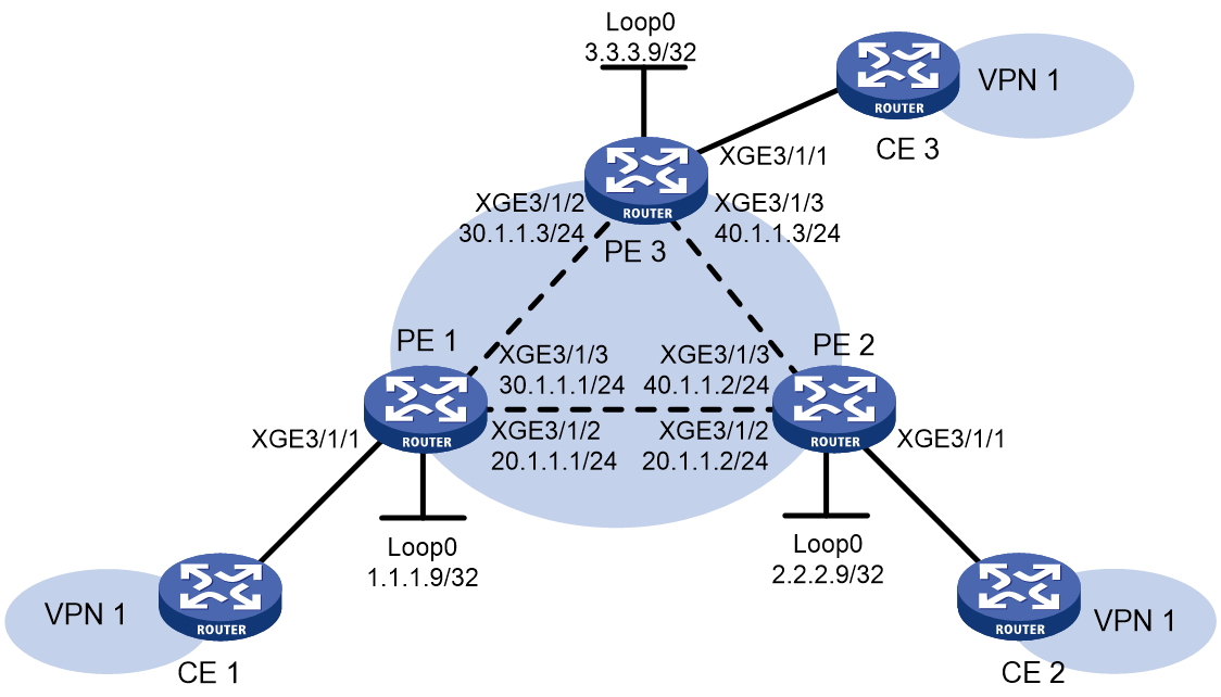
Configure a VSI on each PE, and establish static PWs between the PEs to interconnect the CEs.
Figure 11 Network diagram
Procedure
1. Configure PE 1:
# Configure an LSR ID.
<PE1> system-view
[PE1] interface loopback 0
[PE1-LoopBack0] ip address 1.1.1.9 32
[PE1-LoopBack0] quit
[PE1] mpls lsr-id 1.1.1.9
# Enable L2VPN.
[PE1] l2vpn enable
# Enable global LDP.
[PE1] mpls ldp
[PE1-ldp] quit
# Configure Ten-GigabitEthernet 3/1/2 (the interface connected to PE 2), and enable LDP on the interface.
[PE1] interface ten-gigabitethernet 3/1/2
[PE1-Ten-GigabitEthernet3/1/2] ip address 20.1.1.1 24
[PE1-Ten-GigabitEthernet3/1/2] mpls enable
[PE1-Ten-GigabitEthernet3/1/2] mpls ldp enable
[PE1-Ten-GigabitEthernet3/1/2] quit
# Configure Ten-GigabitEthernet 3/1/3 (the interface connected to PE 3), and enable LDP on the interface.
[PE1] interface ten-gigabitethernet 3/1/3
[PE1-Ten-GigabitEthernet3/1/3] ip address 30.1.1.1 24
[PE1-Ten-GigabitEthernet3/1/3] mpls enable
[PE1-Ten-GigabitEthernet3/1/3] mpls ldp enable
[PE1-Ten-GigabitEthernet3/1/3] quit
# Configure OSPF for LDP to create LSPs.
[PE1] ospf
[PE1-ospf-1] area 0
[PE1-ospf-1-area-0.0.0.0] network 20.1.1.0 0.0.0.255
[PE1-ospf-1-area-0.0.0.0] network 30.1.1.0 0.0.0.255
[PE1-ospf-1-area-0.0.0.0] network 1.1.1.9 0.0.0.0
[PE1-ospf-1-area-0.0.0.0] quit
[PE1-ospf-1] quit
# Create a VSI, specify the peer PEs, and establish static PWs to the peer PEs.
[PE1] vsi svc
[PE1-vsi-svc] pwsignaling static
[PE1-vsi-svc-static] peer 2.2.2.9 pw-id 3 in-label 100 out-label 100
[PE1-vsi-svc-static-2.2.2.9-3] quit
[PE1-vsi-svc-static] peer 3.3.3.9 pw-id 3 in-label 200 out-label 200
[PE1-vsi-svc-static-3.3.3.9-3] quit
[PE1-vsi-svc-static] quit
[PE1-vsi-svc] quit
# Bind interface Ten-GigabitEthernet 3/1/1 to VSI svc.
[PE1] interface ten-gigabitethernet 3/1/1
[PE1-Ten-GigabitEthernet3/1/1] xconnect vsi svc
[PE1-Ten-GigabitEthernet3/1/1] quit
2. Configure PE 2:
# Configure an LSR ID.
<PE2> system-view
[PE2] interface loopback 0
[PE2-LoopBack0] ip address 2.2.2.9 32
[PE2-LoopBack0] quit
[PE2] mpls lsr-id 2.2.2.9
# Enable L2VPN.
[PE2] l2vpn enable
# Enable global LDP.
[PE2] mpls ldp
[PE2-ldp] quit
# Configure Ten-GigabitEthernet 3/1/2 (the interface connected to PE 1), and enable LDP on the interface.
[PE2] interface ten-gigabitethernet 3/1/2
[PE2-Ten-GigabitEthernet3/1/2] ip address 20.1.1.2 24
[PE2-Ten-GigabitEthernet3/1/2] mpls enable
[PE2-Ten-GigabitEthernet3/1/2] mpls ldp enable
[PE2-Ten-GigabitEthernet3/1/2] quit
# Configure Ten-GigabitEthernet 3/1/3 (the interface connected to PE 3), and enable LDP on the interface.
[PE2] interface ten-gigabitethernet 3/1/3
[PE2-Ten-GigabitEthernet3/1/3] ip address 40.1.1.2 24
[PE2-Ten-GigabitEthernet3/1/3] mpls enable
[PE2-Ten-GigabitEthernet3/1/3] mpls ldp enable
[PE2-Ten-GigabitEthernet3/1/3] quit
# Configure OSPF for LDP to create LSPs.
[PE2] ospf
[PE2-ospf-1] area 0
[PE2-ospf-1-area-0.0.0.0] network 20.1.1.0 0.0.0.255
[PE2-ospf-1-area-0.0.0.0] network 40.1.1.0 0.0.0.255
[PE2-ospf-1-area-0.0.0.0] network 2.2.2.9 0.0.0.0
[PE2-ospf-1-area-0.0.0.0] quit
[PE2-ospf-1] quit
# Create a VSI, specify the peer PEs, and establish static PWs to the peer PEs.
[PE2] vsi svc
[PE2-vsi-svc] pwsignaling static
[PE2-vsi-svc-static] peer 1.1.1.9 pw-id 3 in-label 100 out-label 100
[PE2-vsi-svc-static-1.1.1.9-3] quit
[PE2-vsi-svc-static] peer 3.3.3.9 pw-id 3 in-label 300 out-label 300
[PE2-vsi-svc-static-3.3.3.9-3] quit
[PE2-vsi-svc-static] quit
[PE2-vsi-svc] quit
# Bind interface Ten-GigabitEthernet 3/1/1 toVSI svc.
[PE2] interface ten-gigabitethernet 3/1/1
[PE2-Ten-GigabitEthernet3/1/1] xconnect vsi svc
[PE2-Ten-GigabitEthernet3/1/1] quit
3. Configure PE 3:
# Configure an LSR ID.
<PE3> system-view
[PE3] interface loopback 0
[PE3-LoopBack0] ip address 3.3.3.9 32
[PE3-LoopBack0] quit
[PE3] mpls lsr-id 3.3.3.9
# Enable L2VPN.
[PE3] l2vpn enable
# Enable global LDP.
[PE3] mpls ldp
[PE3-ldp] quit
# Configure Ten-GigabitEthernet 3/1/2 (the interface connected to PE 1), and enable LDP on the interface.
[PE3] interface ten-gigabitethernet 3/1/2
[PE3-Ten-GigabitEthernet3/1/2] ip address 30.1.1.3 24
[PE3-Ten-GigabitEthernet3/1/2] mpls enable
[PE3-Ten-GigabitEthernet3/1/2] mpls ldp enable
[PE3-Ten-GigabitEthernet3/1/2] quit
# Configure Ten-GigabitEthernet 3/1/3 (the interface connected to PE 2), and enable LDP on the interface.
[PE3] interface ten-gigabitethernet 3/1/3
[PE3-Ten-GigabitEthernet3/1/3] ip address 40.1.1.3 24
[PE3-Ten-GigabitEthernet3/1/3] mpls enable
[PE3-Ten-GigabitEthernet3/1/3] mpls ldp enable
[PE3-Ten-GigabitEthernet3/1/3] quit
# Configure OSPF for LDP to create LSPs.
[PE3] ospf
[PE3-ospf-1] area 0
[PE3-ospf-1-area-0.0.0.0] network 30.1.1.0 0.0.0.255
[PE3-ospf-1-area-0.0.0.0] network 40.1.1.0 0.0.0.255
[PE3-ospf-1-area-0.0.0.0] network 3.3.3.9 0.0.0.0
[PE3-ospf-1-area-0.0.0.0] quit
[PE3-ospf-1] quit
# Create a VSI, specify the peer PEs, and establish static PWs to the peer PEs.
[PE3] vsi svc
[PE3-vsi-svc] pwsignaling static
[PE3-vsi-svc-static] peer 1.1.1.9 pw-id 3 in-label 200 out-label 200
[PE3-vsi-svc-static-1.1.1.9-3] quit
[PE3-vsi-svc-static] peer 2.2.2.9 pw-id 3 in-label 300 out-label 300
[PE3-vsi-svc-static-2.2.2.9-3] quit
[PE3-vsi-svc-static] quit
[PE3-vsi-svc] quit
# Bind interface Ten-GigabitEthernet3/1/1 to VSI svc.
[PE3] interface ten-gigabitethernet 3/1/1
[PE3-Ten-GigabitEthernet3/1/1] xconnect vsi svc
[PE3-Ten-GigabitEthernet3/1/1] quit
Verifying the configuration
# Verify that two static PWs in up state have been established on PE 1.
[PE1] display l2vpn pw verbose
VSI Name: svc
Peer: 2.2.2.9 PW ID: 3
Signaling Protocol : Static
Link ID : 8 PW State : Up
In Label : 100 Out Label: 100
MTU : 1500
PW Attributes : Main
VCCV CC : -
VCCV BFD : -
Flow Label : -
Control Word : Disabled
Tunnel Group ID : 0x160000001
Tunnel NHLFE IDs : 1027
Admin PW : -
Peer: 3.3.3.9 PW ID: 3
Signaling Protocol : Static
Link ID : 9 PW State : Up
In Label : 200 Out Label: 200
MTU : 1500
PW Attributes : Main
VCCV CC : -
VCCV BFD : -
Flow Label : -
Control Word : Disabled
Tunnel Group ID : 0x260000002
Tunnel NHLFE IDs : 1028
Admin PW : -
Example: Configuring LDP PWs
Network configuration
Configure a VSI on each PE, and establish LDP PWs between the PEs to interconnect the CEs.
Figure 12 Network diagram

Procedure
1. Configure an IGP and public tunnels. (Details not shown.)
2. Configure PE 1:
# Configure basic MPLS.
<PE1> system-view
[PE1] interface loopback 0
[PE1-LoopBack0] ip address 1.1.1.9 32
[PE1-LoopBack0] quit
[PE1] mpls lsr-id 1.1.1.9
[PE1] mpls ldp
[PE1-ldp] quit
# Enable L2VPN.
[PE1] l2vpn enable
# Configure VSI aaa that uses LDP as the PW signaling protocol, and establish PWs to PE 2 and PE 3.
[PE1] vsi aaa
[PE1-vsi-aaa] pwsignaling ldp
[PE1-vsi-aaa-ldp] peer 2.2.2.9 pw-id 500
[PE1-vsi-aaa-ldp-2.2.2.9-500] quit
[PE1-vsi-aaa-ldp] peer 3.3.3.9 pw-id 500
[PE1-vsi-aaa-ldp-3.3.3.9-500] quit
[PE1-vsi-aaa-ldp] quit
[PE1-vsi-aaa] quit
# Bind interface Ten-GigabitEthernet 3/1/1 to VSI aaa.
[PE1] interface ten-gigabitethernet 3/1/1
[PE1-Ten-GigabitEthernet3/1/1] xconnect vsi aaa
[PE1-Ten-GigabitEthernet3/1/1] quit
3. Configure PE 2:
# Configure basic MPLS.
<PE2> system-view
[PE2] interface loopback 0
[PE2-LoopBack0] ip address 2.2.2.9 32
[PE2-LoopBack0] quit
[PE2] mpls lsr-id 2.2.2.9
[PE2] mpls ldp
[PE2-ldp] quit
# Enable L2VPN.
[PE2] l2vpn enable
# Configure VSI aaa that uses LDP as the PW signaling protocol, and establish PWs to PE 1 and PE 3.
[PE2] vsi aaa
[PE2-vsi-aaa] pwsignaling ldp
[PE2-vsi-aaa-ldp] peer 1.1.1.9 pw-id 500
[PE2-vsi-aaa-ldp-1.1.1.9-500] quit
[PE2-vsi-aaa-ldp] peer 3.3.3.9 pw-id 500
[PE2-vsi-aaa-ldp-3.3.3.9-500] quit
[PE2-vsi-aaa-ldp] quit
[PE2-vsi-aaa] quit
# Bind interface Ten-GigabitEthernet 3/1/1 to VSI aaa.
[PE2] interface ten-gigabitethernet 3/1/1
[PE2-Ten-GigabitEthernet3/1/1] xconnect vsi aaa
4. Configure PE 3:
# Configure basic MPLS.
<PE3> system-view
[PE3] interface loopback 0
[PE3-LoopBack0] ip address 3.3.3.9 32
[PE3-LoopBack0] quit
[PE3] mpls lsr-id 3.3.3.9
[PE3] mpls ldp
[PE3-ldp] quit
# Enable L2VPN.
[PE3] l2vpn enable
# Configure VSI aaa that uses LDP as the PW signaling protocol, and establish PWs to PE 1 and PE 2.
[PE3] vsi aaa
[PE3-vsi-aaa] pwsignaling ldp
[PE3-vsi-aaa-ldp] peer 1.1.1.9 pw-id 500
[PE3-vsi-aaa-ldp-1.1.1.9-500] quit
[PE3-vsi-aaa-ldp] peer 2.2.2.9 pw-id 500
[PE3-vsi-aaa-ldp-2.2.2.9-500] quit
[PE3-vsi-aaa-ldp] quit
[PE3-vsi-aaa] quit
# Bind interface Ten-GigabitEthernet 3/1/1 to VSI aaa.
[PE3] interface ten-gigabitethernet 3/1/1
[PE3-Ten-GigabitEthernet3/1/1] xconnect vsi aaa
Verifying the configuration
# Verify that two LDP PWs in up state have been established on PE 1.
[PE1] display l2vpn pw verbose
VSI Name: aaa
Peer: 2.2.2.9 PW ID: 500
Signaling Protocol : LDP
Link ID : 8 PW State : Up
In Label : 1279 Out Label: 1279
MTU : 1500
PW Attributes : Main
VCCV CC : -
VCCV BFD : -
Flow Label : -
Control Word : Disabled
Tunnel Group ID : 0x260000000
Tunnel NHLFE IDs : 1028
Admin PW : -
Peer: 3.3.3.9 PW ID: 500
Signaling Protocol : LDP
Link ID : 9 PW State : Up
In Label : 1278 Out Label: 1277
MTU : 1500
PW Attributes : Main
VCCV CC : -
VCCV BFD : -
Flow Label : -
Control Word : Disabled
Tunnel Group ID : 0x360000001
Tunnel NHLFE IDs : 1029
Admin PW : -
Example: Configuring BGP PWs
Network configuration
Configure a VSI on each PE, and establish BGP PWs between the PEs to interconnect CEs.
Figure 13 Network diagram

Procedure
1. Configure an IGP. (Details not shown.)
2. Configure public tunnels. In this example, an LDP LSP is used as the public tunnel. You must enable MPLS and IPv4 LDP on the interfaces that interconnect the PEs.
3. Configure PE 1:
# Configure basic MPLS.
<PE1> system-view
[PE1] interface loopback 0
[PE1-LoopBack0] ip address 1.1.1.9 32
[PE1-LoopBack0] quit
[PE1] mpls lsr-id 1.1.1.9
[PE1] mpls ldp
[PE1-ldp] quit
# Configure interface Ten-GigabitEthernet 3/1/2 that connects to PE 2, and enable LDP on the interface.
[PE1] interface ten-gigabitethernet 3/1/2
[PE1-Ten-GigabitEthernet3/1/2] ip address 20.1.1.1 24
[PE1-Ten-GigabitEthernet3/1/2] mpls enable
[PE1-Ten-GigabitEthernet3/1/2] mpls ldp enable
[PE1-Ten-GigabitEthernet3/1/2] quit
# Configure interface Ten-GigabitEthernet 3/1/3 that connects to PE 3, and enable LDP on the interface.
[PE1] interface ten-gigabitethernet 3/1/3
[PE1-Ten-GigabitEthernet3/1/3] ip address 30.1.1.1 24
[PE1-Ten-GigabitEthernet3/1/3] mpls enable
[PE1-Ten-GigabitEthernet3/1/3] mpls ldp enable
[PE1-Ten-GigabitEthernet3/1/3] quit
# Establish IBGP connections to PE 2 and PE 3, and use BGP to advertise VPLS label block information.
[PE1] bgp 100
[PE1-bgp-default] peer 2.2.2.9 as-number 100
[PE1-bgp-default] peer 2.2.2.9 connect-interface loopback 0
[PE1-bgp-default] peer 3.3.3.9 as-number 100
[PE1-bgp-default] peer 3.3.3.9 connect-interface loopback 0
[PE1-bgp-default] address-family l2vpn
[PE1-bgp-default-l2vpn] peer 2.2.2.9 enable
[PE1-bgp-default-l2vpn] peer 3.3.3.9 enable
[PE1-bgp-default-l2vpn] quit
[PE1-bgp-default] quit
# Enable L2VPN.
[PE1] l2vpn enable
# Configure VSI aaa to use BGP to establish BGP PWs to PE 2 and PE 3.
[PE1] vsi aaa
[PE1-vsi-aaa] auto-discovery bgp
[PE1-vsi-aaa-auto] route-distinguisher 1:1
[PE1-vsi-aaa-auto] vpn-target 1:1
[PE1-vsi-aaa-auto] signaling-protocol bgp
[PE1-vsi-aaa-auto-bgp] site 1 range 10 default-offset 0
[PE1-vsi-aaa-auto-bgp] quit
[PE1-vsi-aaa-auto] quit
[PE1-vsi-aaa] quit
# Bind interface Ten-GigabitEthernet 3/1/1 to VSI aaa.
[PE1] interface ten-gigabitethernet 3/1/1
[PE1-Ten-GigabitEthernet3/1/1] xconnect vsi aaa
[PE1-Ten-GigabitEthernet3/1/1] quit
4. Configure PE 2:
# Configure basic MPLS.
<PE2> system-view
[PE2] interface loopback 0
[PE2-LoopBack0] ip address 2.2.2.9 32
[PE2-LoopBack0] quit
[PE2] mpls lsr-id 2.2.2.9
[PE2] mpls ldp
[PE2-ldp] quit
# Configure interface Ten-GigabitEthernet 3/1/2 that connects to PE 1, and enable LDP on the interface.
[PE2] interface ten-gigabitethernet 3/1/2
[PE2-Ten-GigabitEthernet3/1/2] ip address 20.1.1.2 24
[PE2-Ten-GigabitEthernet3/1/2] mpls enable
[PE2-Ten-GigabitEthernet3/1/2] mpls ldp enable
[PE2-Ten-GigabitEthernet3/1/2] quit
# Configure interface Ten-GigabitEthernet 3/1/3 that connects to PE 3, and enable LDP on the interface.
[PE2] interface ten-gigabitethernet 3/1/3
[PE2-Ten-GigabitEthernet3/1/3] ip address 40.1.1.2 24
[PE2-Ten-GigabitEthernet3/1/3] mpls enable
[PE2-Ten-GigabitEthernet3/1/3] mpls ldp enable
[PE2-Ten-GigabitEthernet3/1/3] quit
# Establish IBGP connections to PE 1 and PE 3, and use BGP to advertise VPLS label block information.
[PE2] bgp 100
[PE2-bgp-default] peer 1.1.1.9 as-number 100
[PE2-bgp-default] peer 1.1.1.9 connect-interface loopback 0
[PE2-bgp-default] peer 3.3.3.9 as-number 100
[PE2-bgp-default] peer 3.3.3.9 connect-interface loopback 0
[PE2-bgp-default] address-family l2vpn
[PE2-bgp-default-l2vpn] peer 1.1.1.9 enable
[PE2-bgp-default-l2vpn] peer 3.3.3.9 enable
[PE2-bgp-default-l2vpn] quit
[PE2-bgp-default] quit
# Enable L2VPN.
[PE2] l2vpn enable
# Configure VSI aaa to use BGP to establish BGP PWs to PE 1 and PE 3.
[PE2] vsi aaa
[PE2-vsi-aaa] auto-discovery bgp
[PE2-vsi-aaa-auto] route-distinguisher 1:1
[PE2-vsi-aaa-auto] vpn-target 1:1
[PE2-vsi-aaa-auto] signaling-protocol bgp
[PE2-vsi-aaa-auto-bgp] site 2 range 10 default-offset 0
[PE2-vsi-aaa-auto-bgp] quit
[PE2-vsi-aaa-auto] quit
[PE2-vsi-aaa] quit
# Bind interface Ten-GigabitEthernet 3/1/1 to VSI aaa.
[PE2] interface ten-gigabitethernet 3/1/1
[PE2-Ten-GigabitEthernet3/1/1] xconnect vsi aaa
[PE2-Ten-GigabitEthernet3/1/1] quit
5. Configure PE 3:
# Configure basic MPLS.
<PE3> system-view
[PE3] interface loopback 0
[PE3-LoopBack0] ip address 3.3.3.9 32
[PE3-LoopBack0] quit
[PE3] mpls lsr-id 3.3.3.9
[PE3] mpls ldp
[PE3-ldp] quit
# Configure interface Ten-GigabitEthernet 3/1/2 that connects to PE 1, and enable LDP on the interface.
[PE3] interface ten-gigabitethernet 3/1/2
[PE3-Ten-GigabitEthernet3/1/2] ip address 30.1.1.3 24
[PE3-Ten-GigabitEthernet3/1/2] mpls enable
[PE3-Ten-GigabitEthernet3/1/2] mpls ldp enable
[PE3-Ten-GigabitEthernet3/1/2] quit
# Configure interface Ten-GigabitEthernet 3/1/3 that connects to PE 2, and enable LDP on the interface.
[PE3] interface ten-gigabitethernet 3/1/3
[PE3-Ten-GigabitEthernet3/1/3] ip address 40.1.1.3 24
[PE3-Ten-GigabitEthernet3/1/3] mpls enable
[PE3-Ten-GigabitEthernet3/1/3] mpls ldp enable
[PE3-Ten-GigabitEthernet3/1/3] quit
# Establish IBGP connections to PE 1 and PE 2, and use BGP to advertise VPLS label block information.
[PE3] bgp 100
[PE3-bgp-default] peer 1.1.1.9 as-number 100
[PE3-bgp-default] peer 1.1.1.9 connect-interface loopback 0
[PE3-bgp-default] peer 2.2.2.9 as-number 100
[PE3-bgp-default] peer 2.2.2.9 connect-interface loopback 0
[PE3-bgp-default] address-family l2vpn
[PE3-bgp-default-l2vpn] peer 1.1.1.9 enable
[PE3-bgp-default-l2vpn] peer 2.2.2.9 enable
[PE3-bgp-default-l2vpn] quit
[PE3-bgp-default] quit
# Enable L2VPN.
[PE3] l2vpn enable
# Configure VSI aaa to use BGP to establish BGP PWs to PE 1 and PE 2.
[PE3] vsi aaa
[PE3-vsi-aaa] auto-discovery bgp
[PE3-vsi-aaa-auto] route-distinguisher 1:1
[PE3-vsi-aaa-auto] vpn-target 1:1
[PE3-vsi-aaa-auto] signaling-protocol bgp
[PE3-vsi-aaa-auto-bgp] site 3 range 10 default-offset 0
[PE3-vsi-aaa-auto-bgp] quit
[PE3-vsi-aaa-auto] quit
[PE3-vsi-aaa] quit
# Bind interface Ten-GigabitEthernet 3/1/1 to VSI aaa.
[PE3] interface ten-gigabitethernet 3/1/1
[PE3-Ten-GigabitEthernet3/1/1] xconnect vsi aaa
[PE3-Ten-GigabitEthernet3/1/1] quit
Verifying the configuration
# Verify that two BGP PWs in up state have been established on PE 1.
[PE1] display l2vpn pw verbose
VSI Name: aaa
Peer: 2.2.2.9 Remote Site: 2
Signaling Protocol : BGP
Link ID : 9 PW State : Up
In Label : 1295 Out Label: 1025
MTU : 1500
PW Attributes : Main
VCCV CC : -
VCCV BFD : -
Flow Label : -
Control Word : Disabled
Tunnel Group ID : 0x800000160000001
Tunnel NHLFE IDs : 1027
Admin PW : -
Peer: 3.3.3.9 Remote Site: 3
Signaling Protocol : BGP
Link ID : 10 PW State : Up
In Label : 1296 Out Label: 1025
MTU : 1500
PW Attributes : Main
VCCV CC : -
VCCV BFD : -
Flow Label : -
Control Word : Disabled
Tunnel Group ID : 0x800000060000000
Tunnel NHLFE IDs : 1026
Admin PW : -
# Display VPLS label block information received from PE 2 and PE 3 on PE 1.
[PE1] display l2vpn bgp verbose
VSI Name: aaa
Remote Site ID : 2
Offset : 0
RD : 1:1
PW State : Up
Encapsulation : BGP-VPLS
MTU : 1500
Nexthop : 2.2.2.9
Local VC Label : 1295
Remote VC Label : 1025
Local Control Word : Disabled
Remote Control Word: Disabled
Link ID : 9
Local Label Block : 1293/10/0
Remote Label Block : 1024/10/0
Local Flow Label : -
Reomote Flow Label : -
Export Route Target: 1:1
Remote Site ID : 3
Offset : 0
RD : 1:1
PW State : Up
Encapsulation : BGP-VPLS
MTU : 1500
Nexthop : 3.3.3.9
Local VC Label : 1296
Remote VC Label : 1025
Local Control Word : Disabled
Remote Control Word: Disabled
Link ID : 10
Local Label Block : 1293/10/0
Remote Label Block : 1024/10/0
Local Flow Label : -
Reomote Flow Label : -
Export Route Target: 1:1
Example: Configuring BGP auto-discovery LDP PWs
Network configuration
Configure a VSI on each PE. Use BGP to discover remote PEs and use LDP to create PWs among PEs so CEs in different sites of VPN 1 can communicate with each other.
Figure 14 Network diagram

Procedure
1. Configure an IGP and public tunnels. (Details not shown.)
2. Configure public tunnels. In this example, an LDP LSP is used as the public tunnel. You must enable MPLS and IPv4 LDP on the interfaces that interconnect the PEs.
3. Configure PE 1:
# Configure basic MPLS.
<PE1> system-view
[PE1] interface loopback 0
[PE1-LoopBack0] ip address 1.1.1.9 32
[PE1-LoopBack0] quit
[PE1] mpls lsr-id 1.1.1.9
[PE1] mpls ldp
[PE1-ldp] quit
# Configure interface Ten-GigabitEthernet 3/1/2 that connects to PE 2, and enable LDP on the interface.
[PE1] interface ten-gigabitethernet 3/1/2
[PE1-Ten-GigabitEthernet3/1/2] ip address 20.1.1.1 24
[PE1-Ten-GigabitEthernet3/1/2] mpls enable
[PE1-Ten-GigabitEthernet3/1/2] mpls ldp enable
[PE1-Ten-GigabitEthernet3/1/2] quit
# Configure interface Ten-GigabitEthernet 3/1/3 that connects to PE 3, and enable LDP on the interface.
[PE1] interface ten-gigabitethernet 3/1/3
[PE1-Ten-GigabitEthernet3/1/3] ip address 30.1.1.1 24
[PE1-Ten-GigabitEthernet3/1/3] mpls enable
[PE1-Ten-GigabitEthernet3/1/3] mpls ldp enable
[PE1-Ten-GigabitEthernet3/1/3] quit
# Establish IBGP connections to PE 1 and PE 2, and use BGP to advertise VPLS PE information.
[PE1] bgp 100
[PE1-bgp-default] peer 2.2.2.9 as-number 100
[PE1-bgp-default] peer 2.2.2.9 connect-interface loopback 0
[PE1-bgp-default] peer 3.3.3.9 as-number 100
[PE1-bgp-default] peer 3.3.3.9 connect-interface loopback 0
[PE1-bgp-default] address-family l2vpn
[PE1-bgp-default-l2vpn] peer 2.2.2.9 enable
[PE1-bgp-default-l2vpn] peer 3.3.3.9 enable
[PE1-bgp-default-l2vpn] quit
[PE1-bgp-default] quit
# Enable L2VPN.
[PE1] l2vpn enable
# Configure VSI aaa to use BGP to discover remote PEs and use LDP to establish LDP PWs to PE 2 and PE 3.
[PE1] vsi aaa
[PE1-vsi-aaa] auto-discovery bgp
[PE1-vsi-aaa-auto] route-distinguisher 1:1
[PE1-vsi-aaa-auto] vpn-target 1:1
[PE1-vsi-aaa-auto] signaling-protocol ldp
[PE1-vsi-aaa-auto-ldp] vpls-id 100:100
[PE1-vsi-aaa-auto-ldp] quit
[PE1-vsi-aaa-auto] quit
[PE1-vsi-aaa] quit
# Bind interface Ten-GigabitEthernet 3/1/1 to VSI aaa.
[PE1] interface ten-gigabitethernet 3/1/1
[PE1-Ten-GigabitEthernet3/1/1] xconnect vsi aaa
[PE1-Ten-GigabitEthernet3/1/1] quit
4. Configure PE 2:
# Configure basic MPLS.
<PE2> system-view
[PE2] interface loopback 0
[PE2-LoopBack0] ip address 2.2.2.9 32
[PE2-LoopBack0] quit
[PE2] mpls lsr-id 2.2.2.9
[PE2] mpls ldp
[PE2-ldp] quit
# Configure interface Ten-GigabitEthernet 3/1/2 that connects to PE 1, and enable LDP on the interface.
[PE2] interface ten-gigabitethernet 3/1/2
[PE2-Ten-GigabitEthernet3/1/2] ip address 20.1.1.2 24
[PE2-Ten-GigabitEthernet3/1/2] mpls enable
[PE2-Ten-GigabitEthernet3/1/2] mpls ldp enable
[PE2-Ten-GigabitEthernet3/1/2] quit
# Configure interface Ten-GigabitEthernet 3/1/3 that connects to PE 3, and enable LDP on the interface.
[PE2] interface ten-gigabitethernet 3/1/3
[PE2-Ten-GigabitEthernet3/1/3] ip address 40.1.1.2 24
[PE2-Ten-GigabitEthernet3/1/3] mpls enable
[PE2-Ten-GigabitEthernet3/1/3] mpls ldp enable
[PE2-Ten-GigabitEthernet3/1/3] quit
# Establish IBGP connections to PE 1 and PE 3, and use BGP to advertise VPLS PE information.
[PE2] bgp 100
[PE2-bgp-default] peer 1.1.1.9 as-number 100
[PE2-bgp-default] peer 1.1.1.9 connect-interface loopback 0
[PE2-bgp-default] peer 3.3.3.9 as-number 100
[PE2-bgp-default] peer 3.3.3.9 connect-interface loopback 0
[PE2-bgp-default] address-family l2vpn
[PE2-bgp-default-l2vpn] peer 1.1.1.9 enable
[PE2-bgp-default-l2vpn] peer 3.3.3.9 enable
[PE2-bgp-default-l2vpn] quit
[PE2-bgp-default] quit
# Enable L2VPN.
[PE2] l2vpn enable
# Configure VSI aaa to use BGP to discover remote PEs and use LDP to establish LDP PWs to PE 1 and PE 3.
[PE2] vsi aaa
[PE2-vsi-aaa] auto-discovery bgp
[PE2-vsi-aaa-auto] route-distinguisher 1:1
[PE2-vsi-aaa-auto] vpn-target 1:1
[PE2-vsi-aaa-auto] signaling-protocol ldp
[PE2-vsi-aaa-auto-ldp] vpls-id 100:100
[PE2-vsi-aaa-auto-ldp] quit
[PE2-vsi-aaa-auto] quit
[PE2-vsi-aaa] quit
# Bind interface Ten-GigabitEthernet 3/1/1 to VSI aaa.
[PE2] interface ten-gigabitethernet 3/1/1
[PE2-Ten-GigabitEthernet3/1/1] xconnect vsi aaa
[PE2-Ten-GigabitEthernet3/1/1] quit
5. Configure PE 3:
# Configure basic MPLS.
<PE3> system-view
[PE3] interface loopback 0
[PE3-LoopBack0] ip address 3.3.3.9 32
[PE3-LoopBack0] quit
[PE3] mpls lsr-id 3.3.3.9
[PE3] mpls ldp
[PE3-ldp] quit
# Configure interface Ten-GigabitEthernet 3/1/2 that connects to PE 1, and enable LDP on the interface.
[PE3] interface ten-gigabitethernet 3/1/2
[PE3-Ten-GigabitEthernet3/1/2] ip address 30.1.1.3 24
[PE3-Ten-GigabitEthernet3/1/2] mpls enable
[PE3-Ten-GigabitEthernet3/1/2] mpls ldp enable
[PE3-Ten-GigabitEthernet3/1/2] quit
# Configure interface Ten-GigabitEthernet 3/1/3 that connects to PE 2, and enable LDP on the interface.
[PE3] interface ten-gigabitethernet 3/1/3
[PE3-Ten-GigabitEthernet3/1/3] ip address 40.1.1.3 24
[PE3-Ten-GigabitEthernet3/1/3] mpls enable
[PE3-Ten-GigabitEthernet3/1/3] mpls ldp enable
[PE3-Ten-GigabitEthernet3/1/3] quit
# Establish IBGP connections to PE 1 and PE 2, and use BGP to advertise VPLS PE information.
[PE3] bgp 100
[PE3-bgp-default] peer 1.1.1.9 as-number 100
[PE3-bgp-default] peer 1.1.1.9 connect-interface loopback 0
[PE3-bgp-default] peer 2.2.2.9 as-number 100
[PE3-bgp-default] peer 2.2.2.9 connect-interface loopback 0
[PE3-bgp-default] address-family l2vpn
[PE3-bgp-default-l2vpn] peer 1.1.1.9 enable
[PE3-bgp-default-l2vpn] peer 2.2.2.9 enable
[PE3-bgp-default-l2vpn] quit
[PE3-bgp-default] quit
# Enable L2VPN.
[PE3] l2vpn enable
# Configure VSI aaa to use BGP to discover remote PEs and use LDP to establish LDP PWs to PE 1 and PE 2.
[PE3] vsi aaa
[PE3-vsi-aaa] auto-discovery bgp
[PE3-vsi-aaa-auto] route-distinguisher 1:1
[PE3-vsi-aaa-auto] vpn-target 1:1
[PE3-vsi-aaa-auto] signaling-protocol ldp
[PE3-vsi-aaa-auto-ldp] vpls-id 100:100
[PE3-vsi-aaa-auto-ldp] quit
[PE3-vsi-aaa-auto] quit
[PE3-vsi-aaa] quit
# Bind interface Ten-GigabitEthernet 3/1/1 to VSI aaa.
[PE3] interface ten-gigabitethernet 3/1/1
[PE3-Ten-GigabitEthernet3/1/1] xconnect vsi aaa
[PE3-Ten-GigabitEthernet3/1/1] quit
Verifying the configuration
# Verify that two PWs in up state have been established on PE 1.
[PE1] display l2vpn pw verbose
VSI Name: aaa
Peer: 2.2.2.9 VPLS ID: 100:100
Signaling Protocol : LDP
Link ID : 8 PW State : Up
In Label : 1555 Out Label: 1555
MTU : 1500
PW Attributes : Main
VCCV CC : -
VCCV BFD : -
Flow Label : -
Control Word : Disabled
Tunnel Group ID : 0x800000060000000
Tunnel NHLFE IDs : 1029
Admin PW : -
Peer: 3.3.3.9 VPLS ID: 100:100
Signaling Protocol : LDP
Link ID : 9 PW State : Up
In Label : 1554 Out Label: 1416
MTU : 1500
PW Attributes : Main
VCCV CC : -
VCCV BFD : -
Flow Label : -
Control Word : Disabled
Tunnel Group ID : 0x800000160000001
Tunnel NHLFE IDs : 1030
Admin PW : -
# Display LDP PW label information on PE 1.
[PE1] display l2vpn ldp verbose
Peer: 2.2.2.9 VPLS ID: 100:100
VSI Name: aaa
PW State: Up
PW Status Communication: Notification method
PW ID FEC (Local/Remote):
Local AII : (1.1.1.9, 2.2.2.9)
Remote AII : (2.2.2.9, 1.1.1.9)
PW Type : VLAN/VLAN
Group ID : 0/0
Label : 1555/1555
Control Word: Disabled/Disabled
VCCV CV Type: -/-
VCCV CC Type: -/-
Flow Label : -/-
MTU : 1500/1500
PW Status : PW forwarding/PW forwarding
Peer: 3.3.3.9 VPLS ID: 100:100
VSI Name: aaa
PW State: Up
PW Status Communication: Notification method
PW ID FEC (Local/Remote):
Local AII : (1.1.1.9, 3.3.3.9)
Remote AII : (3.3.3.9, 1.1.1.9)
PW Type : VLAN/VLAN
Group ID : 0/0
Label : 1554/1416
Control Word: Disabled/Disabled
VCCV CV Type: -/-
VCCV CC Type: -/-
Flow Label : -/-
MTU : 1500/1500
PW Status : PW forwarding/PW forwarding
Example: Configuring H-VPLS using MPLS access
Network configuration
Configure an H-VPLS network using MPLS access to avoid full-mesh PW configuration. The H-VPLS uses LDP as the PW signaling protocol.
Figure 15 Network diagram
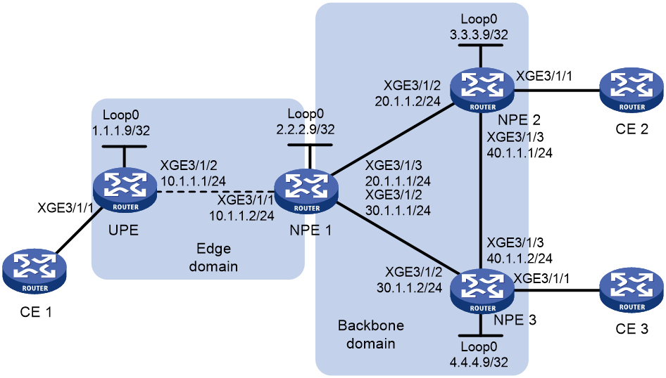
Procedure
1. Configure an IGP and public tunnels. (Details not shown.)
2. Configure public tunnels. In this example, an LDP LSP is used as the public tunnel. You must enable MPLS and IPv4 LDP on the interfaces that interconnect the PEs.
3. Configure UPE:
# Configure basic MPLS.
<UPE> system-view
[UPE] interface loopback 0
[UPE-LoopBack0] ip address 1.1.1.9 32
[UPE-LoopBack0] quit
[UPE] mpls lsr-id 1.1.1.9
[UPE] mpls ldp
[UPE-ldp] quit
# Configure interface Ten-GigabitEthernet 3/1/2 that connects to NPE 1, and enable LDP on the interface.
[UPE] interface ten-gigabitethernet 3/1/2
[UPE-Ten-GigabitEthernet3/1/2] ip address 10.1.1.1 24
[UPE-Ten-GigabitEthernet3/1/2] mpls enable
[UPE-Ten-GigabitEthernet3/1/2] mpls ldp enable
[UPE-Ten-GigabitEthernet3/1/2] quit
# Enable L2VPN.
[UPE] l2vpn enable
# Configure VSI aaa to use LDP to establish a U-PW to NPE 1.
[UPE] vsi aaa
[UPE-vsi-aaa] pwsignaling ldp
[UPE-vsi-aaa-ldp] peer 2.2.2.9 pw-id 500
[UPE-vsi-aaa-ldp-2.2.2.9-500] quit
[UPE-vsi-aaa-ldp] quit
[UPE-vsi-aaa] quit
# Bind interface Ten-GigabitEthernet 3/1/1 to VSI aaa.
[UPE] interface ten-gigabitethernet 3/1/1
[UPE-Ten-GigabitEthernet3/1/1] xconnect vsi aaa
[UPE-Ten-GigabitEthernet3/1/1] quit
4. Configure NPE 1:
# Configure basic MPLS.
<NPE1> system-view
[NPE1] interface loopback 0
[NPE1-LoopBack0] ip address 2.2.2.9 32
[NPE1-LoopBack0] quit
[NPE1] mpls lsr-id 2.2.2.9
[NPE1] mpls ldp
[NPE1–ldp] quit
# Configure interface Ten-GigabitEthernet 3/1/1 that connects to the UPE, and enable LDP on the interface.
[NPE1] interface ten-gigabitethernet 3/1/1
[NPE1-Ten-GigabitEthernet3/1/1] ip address 10.1.1.2 24
[NPE1-Ten-GigabitEthernet3/1/1] mpls enable
[NPE1-Ten-GigabitEthernet3/1/1] mpls ldp enable
[NPE1-Ten-GigabitEthernet3/1/1] quit
# Configure interface Ten-GigabitEthernet 3/1/3 that connects to NPE 2, and enable LDP on the interface.
[NPE1] interface ten-gigabitethernet 3/1/3
[NPE1-Ten-GigabitEthernet3/1/3] ip address 20.1.1.1 24
[NPE1-Ten-GigabitEthernet3/1/3] mpls enable
[NPE1-Ten-GigabitEthernet3/1/3] mpls ldp enable
[NPE1-Ten-GigabitEthernet3/1/3] quit
# Configure interface Ten-GigabitEthernet 3/1/2 that connects to NPE 3, and enable LDP on the interface.
[NPE1] interface ten-gigabitethernet 3/1/2
[NPE1-Ten-GigabitEthernet3/1/2] ip address 30.1.1.1 24
[NPE1-Ten-GigabitEthernet3/1/2] mpls enable
[NPE1-Ten-GigabitEthernet3/1/2] mpls ldp enable
[NPE1-Ten-GigabitEthernet3/1/2] quit
# Enable L2VPN.
[NPE1] l2vpn enable
# Configure VSI aaa that uses LDP as the PW signaling protocol, establish a U-PW to the UPE, and establish N-PWs to NPE 2 and NPE 3.
[NPE1] vsi aaa
[NPE1-vsi-aaa] pwsignaling ldp
[NPE1-vsi-aaa-ldp] peer 1.1.1.9 pw-id 500 no-split-horizon
[NPE1-vsi-aaa-ldp-1.1.1.9-500] quit
[NPE1-vsi-aaa-ldp] peer 3.3.3.9 pw-id 500
[NPE1-vsi-aaa-ldp-3.3.3.9-500] quit
[NPE1-vsi-aaa-ldp] peer 4.4.4.9 pw-id 500
[NPE1-vsi-aaa-ldp-4.4.4.9-500] quit
[NPE1-vsi-aaa-ldp] quit
[NPE1-vsi-aaa] quit
5. Configure NPE 2:
# Configure basic MPLS.
<NPE2> system-view
[NPE2] interface loopback 0
[NPE2-LoopBack0] ip address 3.3.3.9 32
[NPE2-LoopBack0] quit
[NPE2] mpls lsr-id 3.3.3.9
[NPE2] mpls ldp
[NPE2–ldp] quit
# Configure interface Ten-GigabitEthernet 3/1/2 that connects to NPE 1, and enable LDP on the interface.
[NPE2] interface ten-gigabitethernet 3/1/2
[NPE2-Ten-GigabitEthernet3/1/2] ip address 20.1.1.2 24
[NPE2-Ten-GigabitEthernet3/1/2] mpls enable
[NPE2-Ten-GigabitEthernet3/1/2] mpls ldp enable
[NPE2-Ten-GigabitEthernet3/1/2] quit
# Configure interface Ten-GigabitEthernet 3/1/3 that connects to NPE 3, and enable LDP on the interface.
[NPE2] interface ten-gigabitethernet 3/1/3
[NPE2-Ten-GigabitEthernet3/1/3] ip address 40.1.1.1 24
[NPE2-Ten-GigabitEthernet3/1/3] mpls enable
[NPE2-Ten-GigabitEthernet3/1/3] mpls ldp enable
[NPE2-Ten-GigabitEthernet3/1/3] quit
# Enable L2VPN.
[NPE2] l2vpn enable
# Configure VSI aaa that uses LDP as the PW signaling protocol, and establish N-PWs to NPE 1 and NPE 3.
[NPE2] vsi aaa
[NPE2-vsi-aaa] pwsignal ldp
[NPE2-vsi-aaa-ldp] peer 2.2.2.9 pw-id 500
[NPE2-vsi-aaa-ldp-2.2.2.9-500] quit
[NPE2-vsi-aaa-ldp] peer 4.4.4.9 pw-id 500
[NPE2-vsi-aaa-ldp-4.4.4.9-500] quit
[NPE2-vsi-aaa-ldp] quit
[NPE2-vsi-aaa] quit
# Bind interface Ten-GigabitEthernet 3/1/1 to VSI aaa.
[NPE2] interface ten-gigabitethernet 3/1/1
[NPE2-Ten-GigabitEthernet3/1/1] xconnect vsi aaa
[NPE2-Ten-GigabitEthernet3/1/1] quit
6. Configure NPE 3:
# Configure basic MPLS.
<NPE3> system-view
[NPE3] interface loopback 0
[NPE3-LoopBack0] ip address 4.4.4.9 32
[NPE3-LoopBack0] quit
[NPE3] mpls lsr-id 4.4.4.9
[NPE3] mpls ldp
[NPE3–ldp] quit
# Configure interface Ten-GigabitEthernet 3/1/2 that connects to NPE 1, and enable LDP on the interface.
[NPE3] interface ten-gigabitethernet 3/1/2
[NPE3-Ten-GigabitEthernet3/1/2] ip address 30.1.1.2 24
[NPE3-Ten-GigabitEthernet3/1/2] mpls enable
[NPE3-Ten-GigabitEthernet3/1/2] mpls ldp enable
[NPE3-Ten-GigabitEthernet3/1/2] quit
# Configure interface Ten-GigabitEthernet 3/1/3 that connects to NPE 2, and enable LDP on the interface.
[NPE3] interface ten-gigabitethernet 3/1/3
[NPE3-Ten-GigabitEthernet3/1/3] ip address 40.1.1.2 24
[NPE3-Ten-GigabitEthernet3/1/3] mpls enable
[NPE3-Ten-GigabitEthernet3/1/3] mpls ldp enable
[NPE3-Ten-GigabitEthernet3/1/3] quit
# Enable L2VPN.
[NPE3] l2vpn enable
# Configure VSI aaa that uses LDP as the PW signaling protocol, and establish N-PWs to NPE 1 and NPE 2.
[NPE3] vsi aaa
[NPE3-vsi-aaa] pwsignal ldp
[NPE3-vsi-aaa-ldp] peer 2.2.2.9 pw-id 500
[NPE3-vsi-aaa-ldp-2.2.2.9-500] quit
[NPE3-vsi-aaa-ldp] peer 3.3.3.9 pw-id 500
[NPE3-vsi-aaa-ldp-3.3.3.9-500] quit
[NPE3-vsi-aaa-ldp] quit
[NPE3-vsi-aaa] quit
# Bind interface Ten-GigabitEthernet 3/1/1 to VSI aaa.
[NPE3] interface ten-gigabitethernet 3/1/1
[NPE3-Ten-GigabitEthernet3/1/1] xconnect vsi aaa
[NPE3-Ten-GigabitEthernet3/1/1] quit
Verifying the configuration
# Verify that PWs in up state have been established on each PE.
[UPE] display l2vpn pw verbose
VSI Name: aaa
Peer: 2.2.2.9 PW ID: 500
Signaling Protocol : LDP
Link ID : 8 PW State : Up
In Label : 1277 Out Label: 1277
MTU : 1500
PW Attributes : Main
VCCV CC : -
VCCV BFD : -
Flow Label : -
Control Word : Disabled
Tunnel Group ID : 0x460000000
Tunnel NHLFE IDs : 1030
Admin PW : -
[NPE1] display l2vpn pw verbose
VSI Name: aaa
Peer: 1.1.1.9 PW ID: 500
Signaling Protocol : LDP
Link ID : 8 PW State : Up
In Label : 1277 Out Label: 1277
MTU : 1500
PW Attributes : Main, No-split-horizon
VCCV CC : -
VCCV BFD : -
Flow Label : -
Control Word : Disabled
Tunnel Group ID : 0x460000000
Tunnel NHLFE IDs : 1030
Admin PW : -
Peer: 3.3.3.9 PW ID: 500
Signaling Protocol : LDP
Link ID : 9 PW State : Up
In Label : 1276 Out Label: 1275
MTU : 1500
PW Attributes : Main
VCCV CC : -
VCCV BFD : -
Flow Label : -
Control Word : Disabled
Tunnel Group ID : 0x560000001
Tunnel NHLFE IDs : 1031
Admin PW : -
Peer: 4.4.4.9 PW ID: 500
Signaling Protocol : LDP
Link ID : 10 PW State : Up
In Label : 1278 Out Label: 1279
MTU : 1500
PW Attributes : Main
VCCV CC : -
VCCV BFD : -
Flow Label : -
Control Word : Disabled
Tunnel Group ID : 0x570000001
Tunnel NHLFE IDs : 1032
Admin PW : -
[NPE2] display l2vpn pw verbose
VSI Name: aaa
Peer: 2.2.2.9 PW ID: 500
Signaling Protocol : LDP
Link ID : 8 PW State : Up
In Label : 1275 Out Label: 1276
MTU : 1500
PW Attributes : Main
VCCV CC : -
VCCV BFD : -
Flow Label : -
Control Word : Disabled
Tunnel Group ID : 0x660000000
Tunnel NHLFE IDs : 1031
Admin PW : -
Peer: 4.4.4.9 PW ID: 500
Signaling Protocol : LDP
Link ID : 9 PW State : Up
In Label : 1277 Out Label: 1277
MTU : 1500
PW Attributes : Main
VCCV CC : -
VCCV BFD : -
Flow Label : -
Control Word : Disabled
Tunnel Group ID : 0x670000000
Tunnel NHLFE IDs : 1032
Admin PW : -
[NPE3] display l2vpn pw verbose
VSI Name: aaa
Peer: 2.2.2.9 PW ID: 500
Signaling Protocol : LDP
Link ID : 8 PW State : Up
In Label : 1279 Out Label: 1278
MTU : 1500
PW Attributes : Main
VCCV CC : -
VCCV BFD : -
Flow Label : -
Control Word : Disabled
Tunnel Group ID : 0x660000000
Tunnel NHLFE IDs : 1031
Admin PW : -
Peer: 3.3.3.9 PW ID: 500
Signaling Protocol : LDP
Link ID : 9 PW State : Up
In Label : 1277 Out Label: 1277
MTU : 1500
PW Attributes : Main
VCCV CC : -
VCCV BFD : -
Flow Label : -
Control Word : Disabled
Tunnel Group ID : 0x670000000
Tunnel NHLFE IDs : 1032
Admin PW : -
Example: Configuring hub-spoke VPLS
Network configuration
Configure a hub-spoke VPLS network to centralize management of the traffic from each site. The VPLS uses LDP as the PW signaling protocol.
Figure 16 Network diagram
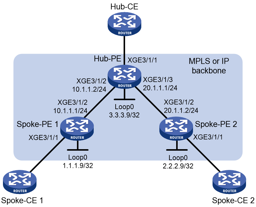
Procedure
1. Configure an IGP and public tunnels. (Details not shown.)
2. Configure public tunnels. In this example, an LDP LSP is used as the public tunnel. You must enable MPLS and IPv4 LDP on the interfaces that interconnect the PEs.
3. Configure Spoke-PE 1:
# Configure basic MPLS.
<Spoke-PE1> system-view
[Spoke-PE1] interface loopback 0
[Spoke-PE1-LoopBack0] ip address 1.1.1.9 32
[Spoke-PE1-LoopBack0] quit
[Spoke-PE1] mpls lsr-id 1.1.1.9
[Spoke-PE1] mpls ldp
[Spoke-PE1-ldp] quit
# Configure interface Ten-GigabitEthernet 3/1/2 that connects to Hub-PE, and enable LDP on the interface.
[Spoke-PE1] interface ten-gigabitethernet 3/1/2
[Spoke-PE1-Ten-GigabitEthernet3/1/2] ip address 10.1.1.1 24
[Spoke-PE1-Ten-GigabitEthernet3/1/2] mpls enable
[Spoke-PE1-Ten-GigabitEthernet3/1/2] mpls ldp enable
[Spoke-PE1-Ten-GigabitEthernet3/1/2] quit
# Enable L2VPN.
[Spoke-PE1] l2vpn enable
# Create VSI aaa, enable hub-spoke capability for the VSI, specify the PW signaling protocol as LDP, establish a PW to Hub-PE, and specify the PW as the hub link.
[Spoke-PE1] vsi aaa hub-spoke
[Spoke-PE1-vsi-aaa] pwsignaling ldp
[Spoke-PE1-vsi-aaa-ldp] peer 3.3.3.9 pw-id 500 hub
[Spoke-PE1-vsi-aaa-ldp-3.3.3.9-500] quit
[Spoke-PE1-vsi-aaa-ldp] quit
[Spoke-PE1-vsi-aaa] quit
# Bind interface Ten-GigabitEthernet 3/1/1 to VSI aaa.
[Spoke-PE1] interface ten-gigabitethernet 3/1/1
[Spoke-PE1-Ten-GigabitEthernet3/1/1] xconnect vsi aaa
[Spoke-PE1-Ten-GigabitEthernet3/1/1] quit
4. Configure Spoke-PE 2:
# Configure basic MPLS.
<Spoke-PE2> system-view
[Spoke-PE2] interface loopback 0
[Spoke-PE2-LoopBack0] ip address 2.2.2.9 32
[Spoke-PE2-LoopBack0] quit
[Spoke-PE2] mpls lsr-id 2.2.2.9
[Spoke-PE2] mpls ldp
[Spoke-PE2–ldp] quit
# Configure interface Ten-GigabitEthernet 3/1/2 that connects to Hub-PE, and enable LDP on the interface.
[Spoke-PE2] interface ten-gigabitethernet 3/1/2
[Spoke-PE2-Ten-GigabitEthernet3/1/2] ip address 20.1.1.2 24
[Spoke-PE2-Ten-GigabitEthernet3/1/2] mpls enable
[Spoke-PE2-Ten-GigabitEthernet3/1/2] mpls ldp enable
[Spoke-PE2-Ten-GigabitEthernet3/1/2] quit
# Enable L2VPN.
[Spoke-PE2] l2vpn enable
# Create VSI aaa, enable hub-spoke capability for the VSI, specify the PW signaling protocol as LDP, establish a PW to Hub-PE, and specify the PW as the hub link.
[Spoke-PE2] vsi aaa hub-spoke
[Spoke-PE2-vsi-aaa] pwsignaling ldp
[Spoke-PE2-vsi-aaa-ldp] peer 3.3.3.9 pw-id 500 hub
[Spoke-PE2-vsi-aaa-ldp-3.3.3.9-500] quit
[Spoke-PE2-vsi-aaa-ldp] quit
[Spoke-PE2-vsi-aaa] quit
# Bind interface Ten-GigabitEthernet 3/1/1 to VSI aaa.
[Spoke-PE2] interface ten-gigabitethernet 3/1/1
[Spoke-PE2-Ten-GigabitEthernet3/1/1] xconnect vsi aaa
[Spoke-PE2-Ten-GigabitEthernet3/1/1] quit
5. Configure Hub-PE:
# Configure basic MPLS.
<Hub-PE> system-view
[Hub-PE] interface loopback 0
[Hub-PE-LoopBack0] ip address 3.3.3.9 32
[Hub-PE-LoopBack0] quit
[Hub-PE] mpls lsr-id 3.3.3.9
[Hub-PE] mpls ldp
[Hub-PE–ldp] quit
# Configure interface Ten-GigabitEthernet 3/1/2 that connects to Spoke-PE 1, and enable LDP on the interface.
[Hub-PE] interface ten-gigabitethernet 3/1/2
[Hub-PE-Ten-GigabitEthernet3/1/2] ip address 10.1.1.2 24
[Hub-PE-Ten-GigabitEthernet3/1/2] mpls enable
[Hub-PE-Ten-GigabitEthernet3/1/2] mpls ldp enable
[Hub-PE-Ten-GigabitEthernet3/1/2] quit
# Configure interface Ten-GigabitEthernet 3/1/3 that connects to Spoke-PE 2, and enable LDP on the interface.
[Hub-PE] interface ten-gigabitethernet 3/1/3
[Hub-PE-Ten-GigabitEthernet3/1/3] ip address 20.1.1.1 24
[Hub-PE-Ten-GigabitEthernet3/1/3] mpls enable
[Hub-PE-Ten-GigabitEthernet3/1/3] mpls ldp enable
[Hub-PE-Ten-GigabitEthernet3/1/3] quit
# Enable L2VPN.
[Hub-PE] l2vpn enable
# Create VSI aaa, enable hub-spoke capability for the VSI, specify the PW signaling protocol as LDP, and establish PWs to Spoke-PE 1 and Spoke-PE 2.
[Hub-PE] vsi aaa hub-spoke
[Hub-PE-vsi-aaa] pwsignaling ldp
[Hub-PE-vsi-aaa-ldp] peer 1.1.1.9 pw-id 500
[Hub-PE-vsi-aaa-ldp-1.1.1.9-500] quit
[Hub-PE-vsi-aaa-ldp] peer 2.2.2.9 pw-id 500
[Hub-PE-vsi-aaa-ldp-2.2.2.9-500] quit
[Hub-PE-vsi-aaa-ldp] quit
[Hub-PE-vsi-aaa] quit
# Bind interface Ten-GigabitEthernet 3/1/1 to VSI aaa, and specify the AC connected to the CE as a hub link.
[Hub-PE] interface ten-gigabitethernet 3/1/1
[Hub-PE-Ten-GigabitEthernet3/1/1] xconnect vsi aaa hub
[Hub-PE-Ten-GigabitEthernet3/1/1] quit
Verifying the configuration
# Verify that PWs in up state have been established on each PE.
[Spoke-PE1] display l2vpn pw verbose
VSI Name: aaa
Peer: 3.3.3.9 PW ID: 500
Signaling Protocol : LDP
Link ID : 8 PW State : Up
In Label : 1276 Out Label: 1274
MTU : 1500
PW Attributes : Main, Hub link
VCCV CC : -
VCCV BFD : -
Flow Label : -
Control Word : Disabled
Tunnel Group ID : 0x560000000
Tunnel NHLFE IDs : 1031
Admin PW : -
[Spoke-PE2] display l2vpn pw verbose
VSI Name: aaa
Peer: 3.3.3.9 PW ID: 500
Signaling Protocol : LDP
Link ID : 8 PW State : Up
In Label : 1275 Out Label: 1273
MTU : 1500
PW Attributes : Main, Hub link
VCCV CC : -
VCCV BFD : -
Flow Label : -
Control Word : Disabled
Tunnel Group ID : 0x660000000
Tunnel NHLFE IDs : 1032
Admin PW : -
[Hub-PE] display l2vpn pw verbose
VSI Name: aaa
Peer: 1.1.1.9 PW ID: 500
Signaling Protocol : LDP
Link ID : 8 PW State : Up
In Label : 1274 Out Label: 1276
MTU : 1500
PW Attributes : Main, Spoke link
VCCV CC : -
VCCV BFD : -
Flow Label : -
Control Word : Disabled
Tunnel Group ID : 0x760000000
Tunnel NHLFE IDs : 1032
Admin PW : -
Peer: 2.2.2.9 PW ID: 500
Signaling Protocol : LDP
Link ID : 9 PW State : Up
In Label : 1273 Out Label: 1275
MTU : 1500
PW Attributes : Main, Spoke link
VCCV CC : -
VCCV BFD : -
Flow Label : -
Control Word : Disabled
Tunnel Group ID : 0x860000001
Tunnel NHLFE IDs : 1033
Admin PW : -
Example: Configuring H-VPLS UPE dual homing
Network configuration
To improve reliability of the H-VPLS network, the UPE establishes a U-PW with NPE 1 and NPE 2. The U-PW between UPE and NPE 1 is the primary PW and that between UPE and NPE 2 is the backup PW. The backup PW works only when the primary PW fails.
The H-VPLS uses LDP as the PW signaling protocol.
Figure 17 Network diagram
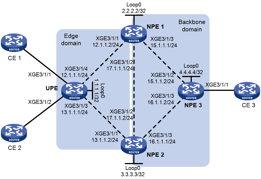
Procedure
1. Configure an IGP and public tunnels. (Details not shown.)
2. Configure public tunnels. In this example, an LDP LSP is used as the public tunnel. You must enable MPLS and IPv4 LDP on the interfaces that interconnect the PEs.
3. Configure UPE:
# Configure basic MPLS.
<UPE> system-view
[UPE] interface loopback 0
[UPE-LoopBack0] ip address 1.1.1.1 32
[UPE-LoopBack0] quit
[UPE] mpls lsr-id 1.1.1.1
[UPE] mpls ldp
[UPE-ldp] quit
# Configure interface Ten-GigabitEthernet 3/1/4 that connects to NPE 1, and enable LDP on the interface.
[UPE] interface ten-gigabitethernet 3/1/4
[UPE-Ten-GigabitEthernet3/1/4] ip address 20.1.1.1 24
[UPE-Ten-GigabitEthernet3/1/4] mpls enable
[UPE-Ten-GigabitEthernet3/1/4] mpls ldp enable
[UPE-Ten-GigabitEthernet3/1/4] quit
# Configure interface Ten-GigabitEthernet 3/1/3 that connects to NPE 2, and enable LDP on the interface.
[UPE] interface ten-gigabitethernet 3/1/3
[UPE-Ten-GigabitEthernet3/1/3] ip address 13.1.1.1 24
[UPE-Ten-GigabitEthernet3/1/3] mpls enable
[UPE-Ten-GigabitEthernet3/1/3] mpls ldp enable
[UPE-Ten-GigabitEthernet3/1/3] quit
# Enable L2VPN.
[UPE] l2vpn enable
# Configure VSI aaa that uses LDP as the PW signaling protocol, and establish the primary PW to NPE 1 and the backup PW to NPE 2.
[UPE] vsi aaa
[UPE-vsi-aaa] pwsignaling ldp
[UPE-vsi-aaa-ldp] peer 2.2.2.2 pw-id 500
[UPE-vsi-aaa-ldp-2.2.2.2-500] backup-peer 3.3.3.3 pw-id 500
[UPE-vsi-aaa-ldp-2.2.2.2-500-backup] quit
[UPE-vsi-aaa-ldp-2.2.2.2-500] quit
[UPE-vsi-aaa-ldp] quit
[UPE-vsi-aaa] quit
# Bind interface Ten-GigabitEthernet 3/1/1 to VSI aaa.
[UPE] interface ten-gigabitethernet 3/1/1
[UPE-Ten-GigabitEthernet3/1/1] xconnect vsi aaa
[UPE-Ten-GigabitEthernet3/1/1] quit
# Bind interface Ten-GigabitEthernet 3/1/2 to VSI aaa.
[UPE] interface ten-gigabitethernet 3/1/2
[UPE-Ten-GigabitEthernet3/1/2] xconnect vsi aaa
[UPE-Ten-GigabitEthernet3/1/2] quit
4. Configure NPE 1:
# Configure basic MPLS.
<NPE1> system-view
[NPE1] interface loopback 0
[NPE1-LoopBack0] ip address 2.2.2.2 32
[NPE1-LoopBack0] quit
[NPE1] mpls lsr-id 2.2.2.2
[NPE1] mpls ldp
[NPE1–ldp] quit
# Configure interface Ten-GigabitEthernet 3/1/1 that connects to the UPE, and enable LDP on the interface.
[NPE1] interface ten-gigabitethernet 3/1/1
[NPE1-Ten-GigabitEthernet3/1/1] ip address 12.1.1.2 24
[NPE1-Ten-GigabitEthernet3/1/1] mpls enable
[NPE1-Ten-GigabitEthernet3/1/1] mpls ldp enable
[NPE1-Ten-GigabitEthernet3/1/1] quit
# Configure interface Ten-GigabitEthernet 3/1/2 that connects to NPE 2, and enable LDP on the interface.
[NPE1] interface ten-gigabitethernet 3/1/2
[NPE1-Ten-GigabitEthernet3/1/2] ip address 17.1.1.1 24
[NPE1-Ten-GigabitEthernet3/1/2] mpls enable
[NPE1-Ten-GigabitEthernet3/1/2] mpls ldp enable
[NPE1-Ten-GigabitEthernet3/1/2] quit
# Configure interface Ten-GigabitEthernet 3/1/3 that connects to NPE 2, and enable LDP on the interface.
[NPE1] interface ten-gigabitethernet 3/1/3
[NPE1-Ten-GigabitEthernet3/1/3] ip address 15.1.1.1 24
[NPE1-Ten-GigabitEthernet3/1/3] mpls enable
[NPE1-Ten-GigabitEthernet3/1/3] mpls ldp enable
[NPE1-Ten-GigabitEthernet3/1/3] quit
# Enable L2VPN.
[NPE1] l2vpn enable
# Configure VSI aaa that uses LDP as the PW signaling protocol, and establish PWs to UPE, NPE 2, and NPE 3.
[NPE1] vsi aaa
[NPE1-vsi-aaa] pwsignaling ldp
[NPE1-vsi-aaa-ldp] peer 1.1.1.1 pw-id 500 no-split-horizon
[NPE1-vsi-aaa-ldp-1.1.1.1-500] quit
[NPE1-vsi-aaa-ldp] peer 3.3.3.3 pw-id 500
[NPE1-vsi-aaa-ldp-3.3.3.3-500] quit
[NPE1-vsi-aaa-ldp] peer 4.4.4.4 pw-id 500
[NPE1-vsi-aaa-ldp-4.4.4.4-500] quit
[NPE1-vsi-aaa-ldp] quit
[NPE1-vsi-aaa] quit
5. Configure NPE 2:
# Configure basic MPLS.
<NPE2> system-view
[NPE2] interface loopback 0
[NPE2-LoopBack0] ip address 3.3.3.3 32
[NPE2-LoopBack0] quit
[NPE2] mpls lsr-id 3.3.3.3
[NPE2] mpls ldp
[NPE2–ldp] quit
# Configure interface Ten-GigabitEthernet 3/1/1 that connects to the UPE, and enable LDP on the interface.
[NPE2] interface ten-gigabitethernet 3/1/1
[NPE2-Ten-GigabitEthernet3/1/1] ip address 13.1.1.2 24
[NPE2-Ten-GigabitEthernet3/1/1] mpls enable
[NPE2-Ten-GigabitEthernet3/1/1] mpls ldp enable
[NPE2-Ten-GigabitEthernet3/1/1] quit
# Configure interface Ten-GigabitEthernet 3/1/2 that connects to NPE 1, and enable LDP on the interface.
[NPE2] interface ten-gigabitethernet 3/1/2
[NPE2-Ten-GigabitEthernet3/1/2] ip address 17.1.1.2 24
[NPE2-Ten-GigabitEthernet3/1/2] mpls enable
[NPE2-Ten-GigabitEthernet3/1/2] mpls ldp enable
[NPE2-Ten-GigabitEthernet3/1/2] quit
# Configure interface Ten-GigabitEthernet 3/1/3 that connects to NPE 3, and enable LDP on the interface.
[NPE2] interface ten-gigabitethernet 3/1/3
[NPE2-Ten-GigabitEthernet3/1/3] ip address 16.1.1.1 24
[NPE2-Ten-GigabitEthernet3/1/3] mpls enable
[NPE2-Ten-GigabitEthernet3/1/3] mpls ldp enable
[NPE2-Ten-GigabitEthernet3/1/3] quit
# Enable L2VPN.
[NPE2] l2vpn enable
# Configure VSI aaa that uses LDP as the PW signaling protocol, and establish PWs to UPE, NPE 1, and NPE 3.
[NPE2] vsi aaa
[NPE2-vsi-aaa] pwsignaling ldp
[NPE2-vsi-aaa-ldp] peer 1.1.1.1 pw-id 500 no-split-horizon
[NPE2-vsi-aaa-ldp-1.1.1.1-500] quit
[NPE2-vsi-aaa-ldp] peer 2.2.2.2 pw-id 500
[NPE2-vsi-aaa-ldp-2.2.2.2-500] quit
[NPE2-vsi-aaa-ldp] peer 4.4.4.4 pw-id 500
[NPE2-vsi-aaa-ldp-4.4.4.4-500] quit
[NPE2-vsi-aaa-ldp] quit
[NPE2-vsi-aaa] quit
6. Configure NPE 3:
# Configure basic MPLS.
<NPE3> system-view
[NPE3] interface loopback 0
[NPE3-LoopBack0] ip address 4.4.4.4 32
[NPE3-LoopBack0] quit
[NPE3] mpls lsr-id 4.4.4.4
[NPE3] mpls ldp
[NPE3–ldp] quit
# Configure interface Ten-GigabitEthernet 3/1/2 that connects to NPE 1, and enable LDP on the interface.
[NPE3] interface ten-gigabitethernet 3/1/2
[NPE3-Ten-GigabitEthernet3/1/2] ip address 15.1.1.2 24
[NPE3-Ten-GigabitEthernet3/1/2] mpls enable
[NPE3-Ten-GigabitEthernet3/1/2] mpls ldp enable
[NPE3-Ten-GigabitEthernet3/1/2] quit
# Configure interface Ten-GigabitEthernet 3/1/3 that connects to NPE 2, and enable LDP on the interface.
[NPE3] interface ten-gigabitethernet 3/1/3
[NPE3-Ten-GigabitEthernet3/1/3] ip address 16.1.1.2 24
[NPE3-Ten-GigabitEthernet3/1/3] mpls enable
[NPE3-Ten-GigabitEthernet3/1/3] mpls ldp enable
[NPE3-Ten-GigabitEthernet3/1/3] quit
# Enable L2VPN.
[NPE3] l2vpn enable
# Configure VSI aaa that uses LDP as the PW signaling protocol, and establish PWs to NPE 1 and NPE 2.
[NPE3] vsi aaa
[NPE3-vsi-aaa] pwsignaling ldp
[NPE3-vsi-aaa-ldp] peer 2.2.2.2 pw-id 500
[NPE3-vsi-aaa-ldp-2.2.2.2-500] quit
[NPE3-vsi-aaa-ldp] peer 3.3.3.3 pw-id 500
[NPE3-vsi-aaa-ldp-3.3.3.3-500] quit
[NPE3-vsi-aaa-ldp] quit
[NPE3-vsi-aaa] quit
# Bind interface Ten-GigabitEthernet 3/1/1 to VSI aaa.
[NPE3] interface ten-gigabitethernet 3/1/1
[NPE3-Ten-GigabitEthernet3/1/1] xconnect vsi aaa
[NPE3-Ten-GigabitEthernet3/1/1] quit
Verifying the configuration
# Verify that PWs in up state have been established on each PE.
[UPE] display l2vpn pw verbose
VSI Name: aaa
Peer: 2.2.2.2 PW ID: 500
Signaling Protocol : LDP
Link ID : 8 PW State : Up
In Label : 1151 Out Label: 1279
Wait to Restore Time: 0 sec
MTU : 1500
PW Attributes : Main
VCCV CC : -
VCCV BFD : -
Flow Label : -
Control Word : Disabled
Tunnel Group ID : 0x260000002
Tunnel NHLFE IDs : 1027
Admin PW : -
Peer: 3.3.3.3 PW ID: 500
Signaling Protocol : LDP
Link ID : 8 PW State : Blocked
In Label : 1150 Out Label: 1279
MTU : 1500
PW Attributes : Backup
VCCV CC : -
VCCV BFD : -
Flow Label : -
Control Word : Disabled
Tunnel Group ID : 0x360000003
Tunnel NHLFE IDs : 1025
Admin PW : -
[NPE1] display l2vpn pw verbose
VSI Name: aaa
Peer: 1.1.1.1 PW ID: 500
Signaling Protocol : LDP
Link ID : 8 PW State : Up
In Label : 1279 Out Label: 1151
MTU : 1500
PW Attributes : Main, No-split-horizon
VCCV CC : -
VCCV BFD : -
Flow Label : -
Control Word : Disabled
Tunnel Group ID : 0x60000000
Tunnel NHLFE IDs : 1026
Admin PW : -
Peer: 3.3.3.3 PW ID: 500
Signaling Protocol : LDP
Link ID : 9 PW State : Up
In Label : 1280 Out Label: 1290
MTU : 1500
PW Attributes : Main
VCCV CC : -
VCCV BFD : -
Flow Label : -
Control Word : Disabled
Tunnel Group ID : 0x160000005
Tunnel NHLFE IDs : 1027
Admin PW : -
Peer: 4.4.4.4 PW ID: 500
Signaling Protocol : LDP
Link ID : 10 PW State : Up
In Label : 1278 Out Label: 1279
MTU : 1500
PW Attributes : Main
VCCV CC : -
VCCV BFD : -
Flow Label : -
Control Word : Disabled
Tunnel Group ID : 0x160000001
Tunnel NHLFE IDs : 1028
Admin PW : -
[NPE2] display l2vpn pw verbose
VSI Name: aaa
Peer: 1.1.1.1 PW ID: 500
Signaling Protocol : LDP
Link ID : 8 PW State : Up
In Label : 1279 Out Label: 1150
MTU : 1500
PW Attributes : Main, No-split-horizon
VCCV CC : -
VCCV BFD : -
Flow Label : -
Control Word : Disabled
Tunnel Group ID : 0x60000000
Tunnel NHLFE IDs : 1026
Admin PW : -
Peer: 2.2.2.2 PW ID: 500
Signaling Protocol : LDP
Link ID : 9 PW State : Up
In Label : 1290 Out Label: 1280
MTU : 1500
PW Attributes : Main
VCCV CC : -
VCCV BFD : -
Flow Label : -
Control Word : Disabled
Tunnel Group ID : 0x160000008
Tunnel NHLFE IDs : 1027
Admin PW : -
Peer: 4.4.4.4 PW ID: 500
Signaling Protocol : LDP
Link ID : 10 PW State : Up
In Label : 1278 Out Label: 1278
MTU : 1500
PW Attributes : Main
VCCV CC : -
VCCV BFD : -
Flow Label : -
Control Word : Disabled
Tunnel Group ID : 0x160000001
Tunnel NHLFE IDs : 1028
Admin PW : -
[NPE3] display l2vpn pw verbose
VSI Name: aaa
Peer: 2.2.2.2 PW ID: 500
Signaling Protocol : LDP
Link ID : 8 PW State : Up
In Label : 1279 Out Label: 1278
MTU : 1500
PW Attributes : Main
VCCV CC : -
VCCV BFD : -
Flow Label : -
Control Word : Disabled
Tunnel Group ID : 0x60000000
Tunnel NHLFE IDs : 1026
Admin PW : -
Peer: 3.3.3.3 PW ID: 500
Signaling Protocol : LDP
Link ID : 9 PW State : Up
In Label : 1278 Out Label: 1278
MTU : 1500
PW Attributes : Main
VCCV CC : -
VCCV BFD : -
Flow Label : -
Control Word : Disabled
Tunnel Group ID : 0x160000001
Tunnel NHLFE IDs : 1027
Admin PW : -
