- Table of Contents
-
- 10-MPLS Configuration Guide
- 00-Preface
- 01-Basic MPLS configuration
- 02-Static LSP configuration
- 03-LDP configuration
- 04-MPLS TE configuration
- 05-Static CRLSP configuration
- 06-RSVP configuration
- 07-Tunnel policy configuration
- 08-MPLS L3VPN configuration
- 09-MPLS L2VPN configuration
- 10-VPLS configuration
- 11-L2VPN access to L3VPN or IP backbone configuration
- 12-MPLS OAM configuration
- 13-MCE configuration
- Related Documents
-
| Title | Size | Download |
|---|---|---|
| 09-MPLS L2VPN configuration | 866.73 KB |
Contents
Remote connection establishment
Local connection establishment
Configuring a remote connection
Configuring a local connection
Configuring a multi-segment PW
Configuring a Layer 3 interface
About configuring a Layer 3 interface
Restrictions and guidelines for configuring a Layer 3 interface
(Optional) Configuring a VLAN tag processing rule for incoming packets
Configuring an Ethernet service instance on an interface
Configuring match criteria for an Ethernet service instance
(Optional) Configuring a VLAN tag processing rule for incoming packets
Binding an AC to a cross-connect
About binding an AC to a cross-connect
Restrictions and guidelines for binding an AC to a cross-connect
Binding a Layer 3 interface to a cross-connect
Binding an Ethernet service instance to a cross-connect
Restrictions and guidelines for configuring PW redundancy
Configuring static PW redundancy
Performing a manual PW switchover
Restrictions and guidelines for configuring a bypass PW
Configuring a single bypass LDP PW
Configuring double bypass LDP PWs
Enabling MPLS L2VPN statistics
Enabling packet statistics on a Layer 3 interface
Enabling packet statistics for an Ethernet service instance
Enabling bandwidth-based load sharing
Enabling SNMP notifications for L2VPN PW
Display and maintenance commands for MPLS L2VPN
MPLS L2VPN configuration examples
Example: Configuring local MPLS L2VPN connections
Example: Configuring a static PW
Example: Configuring an LDP PW
Example: Configuring a bypass PW
Example: Configuring an intra-domain multi-segment PW
Example: Configuring an inter-domain multi-segment PW
Configuring MPLS L2VPN
MPLS L2VPN provides point-to-point and point-to-multipoint connections. This chapter describes only the MPLS L2VPN technologies that provide point-to-point connections. For information about the MPLS L2VPN technologies that provide point-to-multipoint connections, see "Configuring VPLS."
About MPLS L2VPN
MPLS L2VPN is an implementation of Pseudo Wire Emulation Edge-to-Edge (PWE3). It offers Layer 2 VPN services over an MPLS or IP backbone. MPLS L2VPN can transparently transmit Layer 2 data for different data link layer protocols such as Ethernet and ATM.
Basic concepts of MPLS L2VPN
CE
A customer edge (CE) is a customer device directly connected to the service provider network.
PE
A provider edge (PE) is a service provider device connected to one or more CEs. It provides VPN access by mapping and forwarding packets between user networks and public tunnels.
AC
An attachment circuit (AC) is a link between a CE and a PE, such as an ATM VPI/VCI, Ethernet interface, VLAN, or PPP connection.
PW
A Pseudowire (PW) is a virtual bidirectional connection between two PEs. An MPLS PW comprises a pair of LSPs in opposite directions.
Public tunnel
A public tunnel is a connection that carries one or more PWs across the MPLS or IP backbone. It can be an LSP tunnel, an MPLS TE tunnel, or a GRE tunnel.
Cross-connect
A cross-connect connects two physical or virtual circuits such as ACs and PWs. It switches packets between the two physical or virtual circuits. Cross-connects include AC to AC cross-connect, AC to PW cross-connect, and PW to PW cross-connect.
Site ID
A site ID uniquely identifies a site in a VPN. Sites in different VPNs can have the same site ID.
RD
A route distinguisher (RD) is added before a site ID to distinguish the sites that have the same site ID but reside in different VPNs. An RD and a site ID uniquely identify a VPN site.
Label block
A label block is a set of labels. It includes the following parameters:
· Label base—The LB specifies the initial label value of the label block. A PE automatically selects an LB value that cannot be manually modified.
· Label range—The LR specifies the number of labels that the label block contains. The LB and LR determine the labels contained in the label block. For example, if the LB is 1000 and the LR is 5, the label block contains labels 1000 through 1004.
· Label-block offset—The LO specifies the offset of a label block. If the existing label block becomes insufficient as the VPN sites increase, you can add a new label block to enlarge the label range. A PE uses an LO to identify the position of the new label block. The LO value of a label block is the sum of the LRs of all previously assigned label blocks. For example, if the LR and LO of the first label block are 10 and 0, the LO of the second label block is 10. If the LR of the second label block is 20, the LO of the third label block is 30.
A label block with LB, LO, and LR as 1000, 10, and 5, respectively, is represented as 1000/10/5.
For example, a VPN has 10 sites, and a PE assigns the first label block LB1/0/10 to the VPN. When another 15 sites are added, the PE keeps the first label block and assigns the second label block LB2/10/15 to extend the network. LB1 and LB2 are the initial label values that are randomly selected by the PE.
Route target
PEs use the BGP route target attribute (also called VPN target attribute) to manage BGP L2VPN information advertisement. PEs support the following types of route target attributes:
· Export target attribute—When a PE sends L2VPN information to the peer PE in a BGP update message, it sets the route target attribute in the update message to an export target. L2VPN information includes the site ID, RD, and label block.
· Import target attribute—When a PE receives an update message from the peer PE, it checks the route target attribute in the update message. If the route target value matches an import target, the PE accepts the L2VPN information in the update message.
Route target attributes determine from which PEs a PE can receive L2VPN information.
MPLS L2VPN network models
MPLS L2VPN network models include the remote connection and local connection models.
As shown in Figure 1, the remote connection model connects two CEs through a PW on an MPLS or IP backbone.
Figure 1 Remote connection model
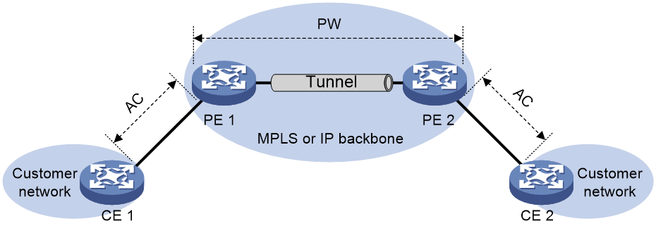
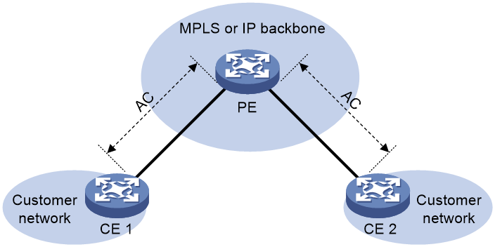
As shown in Figure 2, the local connection model connects two CEs to the same PE so the CEs can communicate through the PE.
Figure 2 Local connection model
Remote connection establishment
To set up a remote MPLS L2VPN connection:
1. Set up a public tunnel to carry one or more PWs between PEs.
2. Set up a PW to connect customer networks.
3. Set up an AC between a PE and a CE.
4. Bind the AC to the PW.
After the PE receives packets from the AC, it adds the PW label into the packets and sends the packets to the peer PE through the public tunnel.
After the peer PE receives the packets from the public tunnel, it removes the PW label of the packets and forwards the packets to the AC bound to the PW.
Setting up a public tunnel
The public tunnel can be an LSP, MPLS TE, or GRE tunnel.
If multiple public tunnels exist between two PEs, you can configure a tunnel policy to control tunnel selection. For more information about tunnel policies, see "Configuring tunnel policies."
If a PW is established over an LSP or MPLS TE tunnel, packets on the PW have two labels. The outer label is the public LSP or MPLS TE tunnel label that MPLS uses to forward the packet to the peer PE. The inner label is the PW label that the peer PE uses to forward the packet to the destination CE.
Setting up a PW
PWs include static PWs, LDP PWs, BGP PWs, and Circuit Cross Connect (CCC) PWs.
· Static PW establishment
To establish a static PW, configure the peer PE address, and the incoming and outgoing PW labels for the PW on the two PEs. Static PWs consume a small amount of resources but have complex configurations.
· LDP PW establishment
To establish an LDP PW, configure LDP and specify the peer PE address on the two PEs. LDP defines a new FEC type named PW ID FEC for PEs to exchange PW-label bindings. The new FEC type uses a PW ID and a PW data encapsulation type to identify a PW. The PW ID is the ID of the PW between PEs. The PW data encapsulation type specifies the encapsulation type for data transmitted over the PW, such as ATM, Ethernet, or VLAN. PEs advertise the PW label and PW ID FEC in label mapping messages to create a PW. Dynamic PWs have simple configurations but consume more resources than static PWs.
· BGP PW establishment
To establish BGP PWs, BGP advertises label block information in an extended BGP update to PEs in the same VPN. Each PE uses the received label block information to calculate outgoing labels and uses its own label block to calculate incoming labels. After two PEs complete label calculation, a BGP PW is established between them.
BGP PWs have the following features:
¡ Simplified configuration—There is no need to manually specify peer PEs. A PE automatically find peer PEs after receiving label block information from the peer PEs.
¡ Reduced workload—Label block advertisement enables assigning labels for multiple PWs at one time.
Setting up an AC
Set up an AC by configuring a link layer connection (such as a PPP connection) between a PE and a CE.
An AC can be one of the following types on a PE:
· Layer 3 physical interface—Transparently forwards received packets over the bound PW. The interface can be an Ethernet interface or an ATM interface.
· Layer 3 subinterface—Forwards packets received from the corresponding link (VLAN, ATM VPC, or ATM VCC) to the bound PW. In this mode, VLANs are unique on a per interface basis rather than on a global basis.
· Ethernet service instance on a Layer 2 Ethernet interface or Layer 2 aggregate interface—Forwards packets that are received on the interface and meet the match criteria of the Ethernet service instance to the bound PW. If the match criterion is VLAN ID, the VLAN is unique on a per interface basis rather than on a global basis.
|
|
NOTE: When VLANs are globally unique, packets with the same VLAN ID are forwarded over the PW bound with that VLAN ID regardless of the receiving interfaces. If VLANs are unique on a per interface basis, packets with the same VLAN ID from different interfaces can be forwarded over different PWs. |
Binding the AC to the PW
Bind the Layer 3 physical interface, Layer 3 subinterface, or Ethernet service instance to the PW, so the PE forwards packets between the AC and the PW.
Local connection establishment
To set up a local MPLS L2VPN connection between two CEs:
1. Set up ACs:
Configure the link layer protocol to set up an AC between the PE and each CE. For more information, see "Setting up an AC."
2. Bind the two ACs:
Bind the PE's interfaces connected to the two CEs so the PE can forward packets between CEs.
PW data encapsulation types
MPLS L2VPN transports Layer 2 data of different data link layer protocols through PWs. A PE encapsulates a Layer 2 packet received from an AC according to the PW data encapsulation type.
Relationship between AC types and PW data encapsulation types
The PW data encapsulation type is determined by the link type of the AC, as shown in Table 1.
Table 1 Relationship between AC types and PW data encapsulation types
|
AC type |
PW data encapsulation type |
|
Ethernet |
Ethernet |
|
VLAN |
Ethernet over MPLS
Ethernet over MPLS uses MPLS L2VPN to connect Ethernets, and delivers Ethernet packets through a PW over the MPLS backbone.
The following PW data encapsulation types are available for Ethernet over MPLS:
· Ethernet—P-tag is not transferred on a PW.
¡ For a packet from a CE:
- If the packet contains a P-tag, the PE removes the P-tag, and adds a PW label and an outer tag into the packet before forwarding it.
- If the packet contains no P-tag, the PE directly adds a PW label and an outer tag into the packet before forwarding it.
¡ For a packet to a CE:
- If the access mode is configured as VLAN by using the ac interface command, the PE adds a P-tag into the packet before sending it to the CE.
- If the access mode is configured as Ethernet by using the ac interface command, the PE directly sends the packet to the CE.
You cannot rewrite or remove existing tags.
· VLAN—Packets transmitted over a PW must carry a P-tag.
¡ For a packet from a CE:
- If the peer PE does not require the ingress to rewrite the P-tag, the PE keeps the P-tag unchanged for the packet, and then encapsulates the packet. If the packet contains no P-tag, the PE adds a null label (the label value is 0) into the packet, and then encapsulates the packet.
- If the peer PE requires the ingress to rewrite the P-tag, the PE changes the P-tag to the expected VLAN tag (the tag value might be 0), and then adds a PW label and an outer tag into the packet. If the packet contains no P-tag, the PE adds a VLAN tag expected by the peer PE (the tag value might be 0), and then adds a PW label and an outer tag into the packet.
¡ For a packet to a CE:
- If the access mode is configured as VLAN by using the ac interface command, the PE rewrites or retains the P-tag before forwarding the packet.
- If the access mode is configured as Ethernet by using the ac interface command, the PE removes the P-tag before forwarding the packet.
Ethernet over MPLS supports the following modes:
· Port mode—A Layer 3 Ethernet interface is bound to a PW. Packets received from the Layer 3 Ethernet interface are forwarded through the bound PW. The default PW data encapsulation type for port mode is Ethernet.
Figure 3 Packet encapsulation in port mode
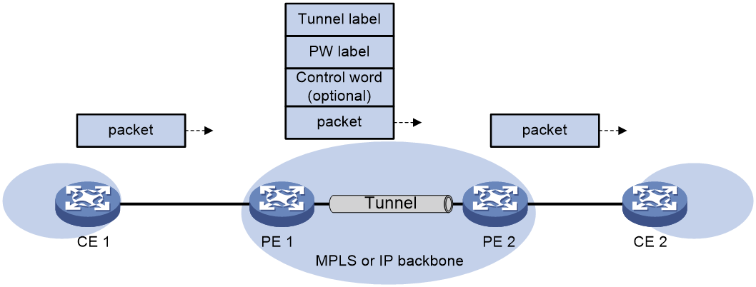
· VLAN mode—A Layer 3 Ethernet subinterface is bound to a PW. Packets received from the VLAN are forwarded through the bound PW. The peer PE can modify the VLAN tag as needed. The default PW data encapsulation type for VLAN mode is VLAN.
· Flexible mode—An Ethernet service instance on a Layer 2 Ethernet interface or Layer 2 aggregate interface is bound to a PW. Packets that are received from the interface and meet the match criteria of the Ethernet service instance are forwarded through the bound PW. You can configure flexible match criteria for the Ethernet service instance. For example, configure the Ethernet service instance to match all packets, tagged packets, or untagged packets. The default PW data encapsulation type for flexible mode is VLAN. Flexible mode can also implement the port and VLAN modes through match criteria configuration.
Control word
The control word field is between the MPLS label stack and the Layer 2 data. It carries control information for the Layer 2 frame, for example, the sequence number.
The control word feature has the following functions:
· Avoids fragment disorder. In multipath forwarding, fragments received might be disordered. The control word feature reorders the fragments according to the sequence number carried in the control word field.
· Transfers specific Layer 2 frame flags.
· Identifies the original payload length for packets that include padding.
When the PW data encapsulation type is , packets on the PW always carry the control word field, and the control word feature cannot be disabled.
When the PW data encapsulation type is Ethernet or VLAN, the control word field is optional. You can configure whether to carry the control word field in packets sent on the PW. If you enable the control word feature on both PEs, packets transmitted on the PW carry the control word field. Otherwise, the packets do not carry the control word field.
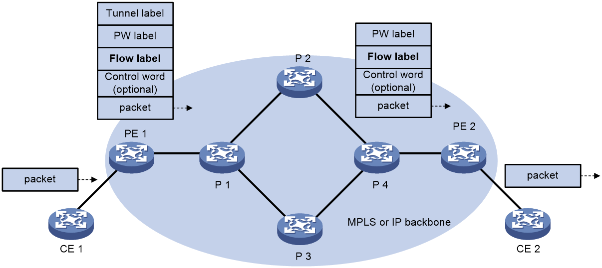
Flow label
Packets carrying different types of traffic might be transmitted through the same PW and encapsulated with the same PW label. The P devices forward the traffic flows of a PW over the same path even if Equal Cost Multiple Paths (ECMPs) exist.
The L2VPN flow label feature can enable a P device to perform load sharing on packets based on the flow types.
After you configure this feature, the P and PE devices process packets as follows:
· When the ingress PE encapsulates a packet, it adds a flow label before it adds a PW label, as shown in Figure 4.
The ingress PE adds different flow labels for packets of different traffic types.
· The P devices perform load sharing on packets based on the flow labels.
· The egress PE removes both the PW and flow labels from a packet before forwarding the packet.
Figure 4 L2VPN flow label feature
You can enable the flow label sending, receiving, or both sending and receiving capabilities on a PE.
· The sending capability enables a PE to send packets with flow labels. The PE adds a flow label before it adds a PW label to a packet during PW encapsulation.
· The receiving capability enables a PE to identify the flow label in a received packet and removes the flow label before forwarding the packet.
For two PE to successfully negotiate the flow label capabilities, make sure one end has the sending capability and the other end has the receiving capability.
For static PWs, you must manually configure flow label capabilities for the local and remote PEs. For dynamic PWs, you can configure the local and remote PEs to negotiate the flow label capabilities or manually configure flow label capabilities for the PEs.
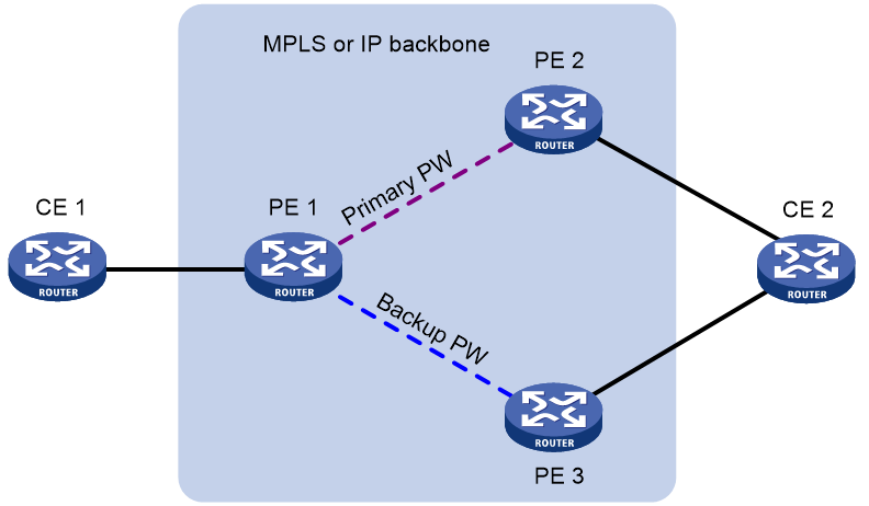
PW redundancy
PW redundancy provides redundant links between PEs so that the customer networks can communicate when the path over one PW fails. As shown in Figure 5, PE 1 establishes two PWs (one primary and one backup). The CEs communicate through the primary PW. When the primary PW fails, PE 1 brings up the backup PW and forwards packets from CE 1 to CE 2 through the backup PW. When CE 2 receives the packets, it updates its MAC address table, so that packets from CE 2 to CE 1 also travel through the backup PW. Only static PWs and LDP PWs support PW redundancy.
The MPLS L2VPN determines whether the primary PW fails according to the LDP session status or the BFD result. The backup PW is used when one of the following conditions exists:
· The public tunnel of the primary PW is deleted, or BFD detects that the public tunnel has failed.
· The primary PW is deleted because the LDP session between PEs goes down, or BFD detects that the primary PW has failed.
· A manual PW switchover is performed.
A PW can be in either of the following states:
· Active—The PW is in active state and can forward packets.
· Standby—The PW is in standby state and cannot forward packets.
LDP PWs support the independent and master/slave PW redundancy operation modes.
· Independent mode—The two PEs of a PW use LDP to advertise their respective PW active/standby state to each other. A PW can forward traffic only when it is up and active at both ends of the PW. In this mode, make sure both PEs of a PW use the independent PW redundancy operation mode.
· Master/slave mode—One PE of a PW operates as the master node and the other PE operates as the slave node. The master PE determines the PW active/standby state and then uses LDP to advertise the PW state to the slave PE. The slave PE uses the same PW state as the master PE based on the information received from the master PE. In this way, the master and slave PEs for the set of redundant PWs can use the same active PW to forward user packets.
A slave node does not advertise the PW active/standby state to the master node, and the master node ignores the PW active/standby state received from the slave nodes.
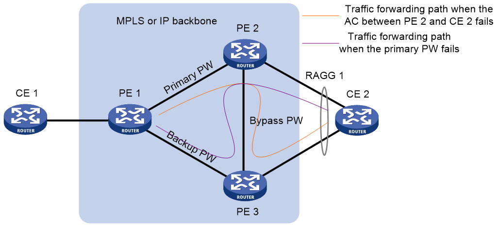
Bypass PW
As shown in Figure 6 and Figure 7, traffic forwarding failure might occur in the following cases:
· When the AC between PE 2 and CE 2 fails, PE 1 cannot immediately detect the failure and bring up the backup PW.
· When the primary PW fails, CE 2 cannot immediately detect the failure and still sends the traffic to PE 2.
To resolve the problem, you can create a single bypass PW or double bypass PWs between PE 2 and PE 3.
Single bypass PW
As shown in Figure 6, after you create a single bypass PW between PE 2 and PE 3, the bypass PW provides both PW bypass and AC bypass. Traffic is forwarded as follows:
· When the AC between PE 2 and CE 2 fails, traffic from CE 1 to CE 2 goes through the path CE 1—PE 1—PE 2—PE 3—CE 2.
· When the primary PW fails, traffic from CE 2 to CE 1 goes through the path CE 2—PE 2—PE 3—PE 1—CE 1.
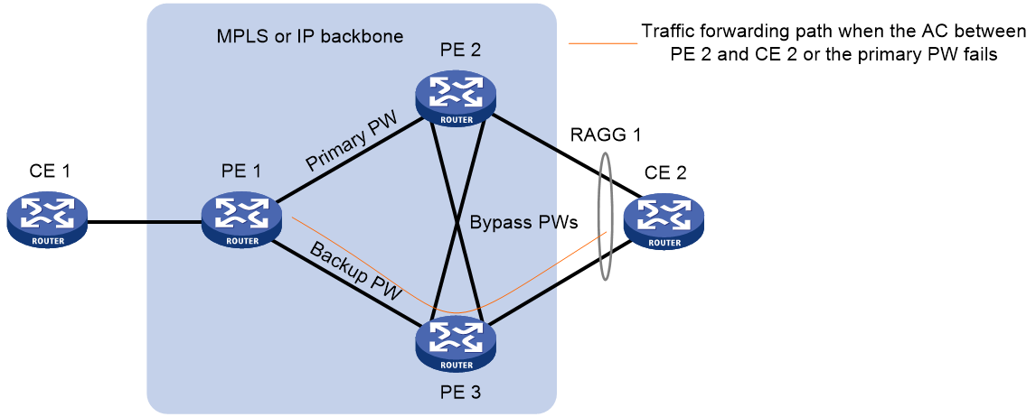
Double bypass PWs
Double bypass PWs refer to an AC-bypass PW used to forward traffic when the AC fails and a PW-bypass PW used to forward traffic when the primary PW fails. Compared with single bypass PWs, double bypass PWs reduce the traffic switchover time and provide higher reliability.
As shown in Figure 7, after you create double bypass PWs between PE 2 and PE 3, traffic is forwarded as follows:
· When the AC between PE 2 and CE 2 fails, traffic from CE 1 to CE 2 goes through the path CE 1—PE 1—PE 2—PE 3—CE 2. The traffic is forwarded from PE 2 to PE 3 through the AC-bypass PW. After the primary/backup PW switchover completes, the traffic is switched to the backup PW, so the final traffic forwarding path is CE 1—PE 1—PE 3—CE 2.
· When the primary PW fails, traffic from CE 2 to CE 1 goes through the path CE 2—PE 2—PE 3—PE 1—CE 1. The traffic is forwarded from PE 2 to PE 3 through the PW-bypass PW. . After the primary/backup PW switchover completes, the traffic is switched to the backup PW, so the final traffic forwarding path is CE 2—PE 3—PE 1—CE 1.
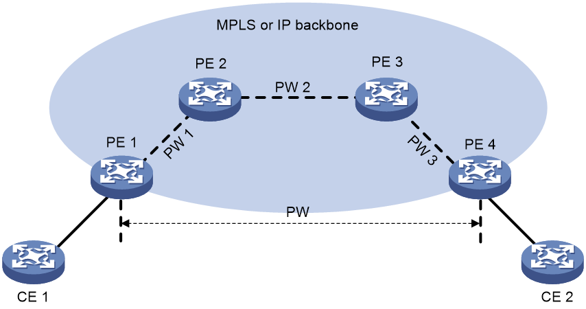
Multi-segment PW
Working mechanism
A multi-segment PW includes multiple concatenated static or LDP PWs. Creating two PWs for a cross-connect on a PE can concatenate the two PWs. Upon receiving a packet from one PW, the PE removes the tunnel ID and PW label of the packet, adds the PW label of the other PW, and forwards the packet over the public tunnel. Only static and LDP PWs can form a multi-segment PW.
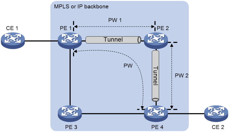
As shown in Figure 8, to create a multi-segment PW between PE 1 and PE 4, you can concatenate PW 1 and PW 2 on PE 2, and PW 2 and PW 3 on PE 3.
Multi-segment PWs include intra-domain multi-segment PWs and inter-domain multi-segment PWs.
Intra-domain multi-segment PW
An intra-domain multi-segment PW has concatenated PWs within an AS. You can create an intra-domain multi-segment PW between two PEs that have no public tunnel to each other.
As shown in Figure 9, there is no public tunnel between PE 1 and PE 4. There is a public tunnel between PE 1 and PE 2 and a public tunnel between PE 2 and PE 4. To create an intra-domain multi-segment PW between PE 1 and PE 4, you can perform the following operations:
1. Create a PW between PE 1 and PE 2 (PW 1) and a PW between PE 2 and PE 4 (PW 2).
2. Concatenate the two PWs on PE 2.
Intra-domain multi-segment PWs can fully use existing public tunnels to reduce end-to-end public tunnels.
Figure 9 Intra-domain multi-segment PW
Inter-domain multi-segment PW
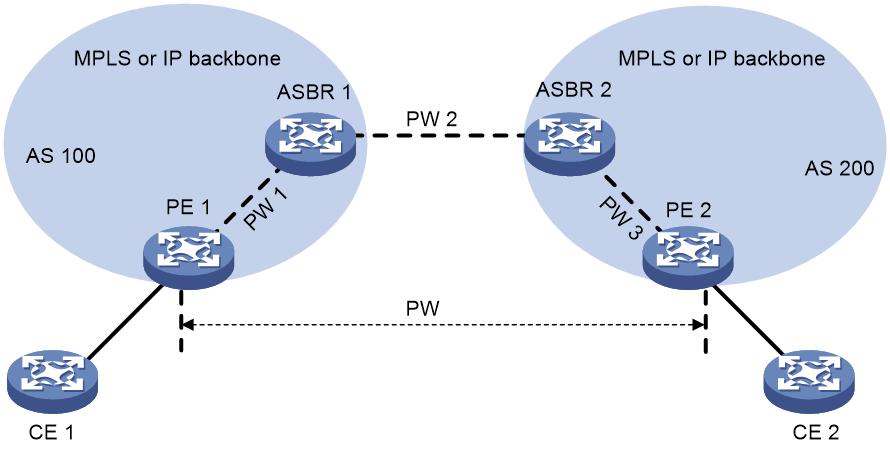
An inter-domain multi-segment PW has concatenated PWs in different ASs, and is a method for inter-AS option B networking.
As shown in Figure 10, to create an inter-domain multi-segment PW between PE 1 and PE 2 in different ASs, you can perform the following operations:
· Concatenate PW 1 and PW 2 on ASBR 1.
· Concatenate PW 2 and PW 3 on ASBR 2.
Figure 10 Inter-domain multi-segment PW
VCCV
Virtual Circuit Connectivity Verification (VCCV) is an OAM feature for L2VPN. It verifies the connectivity of PWs on the data plane. VCCV includes the following modes:
· Manual mode—Use the ping mpls pw command to manually test the connectivity of a PW.
· Auto mode—Configure BFD to automatically test the connectivity of a PW.
For more information about VCCV, see "Configuring MPLS OAM."
MPLS L2VPN tasks at a glance
Configuring a remote connection
2. Configuring an AC
¡ Configuring a Layer 3 interface
¡ Configuring an Ethernet service instance on an interface
3. Configuring a cross-connect
Configure a static PW, LDP PW, BGP PW, EVPN PW as needed.
¡ (Optional.) Configuring a PW class
5. Binding an AC to a cross-connect
6. (Optional.) Improving the MPLS L2VPN network reliability
7. (Optional.) Maintaining an MPLS L2VPN network
¡ Enabling MPLS L2VPN statistics
¡ Enabling bandwidth-based load sharing
¡ Enabling SNMP notifications for L2VPN PW
Configuring a local connection
2. Configuring an AC
To create a local connection, you must configure two ACs.
Choose one of the following tasks according to the AC type:
¡ Configuring a Layer 3 interface
¡ Configuring an Ethernet service instance on an interface
3. Configuring a cross-connect
4. Binding an AC to a cross-connect
Perform this task to bind the two ACs to the same cross-connect.
5. (Optional.) Enabling packet statistics for an AC
¡ Enabling packet statistics on a Layer 3 interface
¡ Enabling packet statistics for an Ethernet service instance
Configuring a multi-segment PW
2. Configuring a cross-connect
Configure two static or LDP PWs for a cross-connect to concatenate the two PWs.
¡ (Optional.) Configuring a PW class
4. (Optional.) Maintaining an MPLS L2VPN network
¡ Enabling bandwidth-based load sharing
¡ Enabling SNMP notifications for L2VPN PW
Prerequisites for MPLS L2VPN
To establish an MPLS L2VPN, you must perform the following tasks:
1. Configure an IGP to achieve IP connectivity within the backbone.
2. Configure basic MPLS, LDP, GRE, or MPLS TE to set up public tunnels across the backbone.
Enabling L2VPN
Prerequisites
Before you enable L2VPN, perform the following tasks:
· Configure an LSR ID for the PE with the mpls lsr-id command.
· Enable MPLS with the mpls enable command on the core-facing interface of the PE.
For more information about the mpls lsr-id and mpls enable commands, see MPLS Command Reference.
Procedure
1. Enter system view.
system-view
2. Enable L2VPN.
l2vpn enable
By default, L2VPN is disabled.
Configuring a Layer 3 interface
About configuring a Layer 3 interface
Configure a Layer 3 interface on a PE to establish an AC to the CE.
Restrictions and guidelines for configuring a Layer 3 interface
The PE forwards packets received from a Layer 3 interface through the bound PW without network layer processing. Therefore, the Layer 3 interface does not need an IP address.
Both the PW data encapsulation type and the AC access mode are Ethernet for Layer 3 Ethernet interfaces (including Layer 3 Ethernet interfaces and VE-L2VPN interfaces). Both the PW data encapsulation type and AC access mode are VLAN for Layer 3 subinterfaces.
(Optional) Configuring a VLAN tag processing rule for incoming packets
Restrictions and guidelines
In standard system operating mode, this feature is available only for the following cards:
|
Card category |
Cards |
|
CEPC |
CEPC-CQ8L, CEPC-CQ8LA, CEPC-CQ8L1A, CEPC-CQ16L1 |
|
CSPEX |
CSPEX-1802X, CSPEX-1802XA, CSPEX-2612XA, CSPEX-1812X-E, CSPEX-2304X-G, CSPEX-1502XA |
|
SPE |
RX-SPE200-E |
In SDN-WAN system operating mode, this feature is available only for the following cards:
|
Card category |
Cards |
|
CEPC |
CEPC-XP4LX, CEPC-XP24LX, CEPC-XP48RX, CEPC-CP4RX, CEPC-CP4RXA, CEPC-CP4RX-L, CEPC-CQ8L, CEPC-CQ8LA, CEPC-CQ8L1A, CEPC-CQ16L1 |
|
CSPEX |
CSPEX-1304X, CSPEX-1404X, CSPEX-1502X, CSPEX-1504X, CSPEX-1504XA, CSPEX-1602X, CSPEX-1602XA, CSPEX-1804X, CSPEX-1512X, CSPEX-1612X, CSPEX-1812X, CSPEX-1802X, CSPEX-1802XA, CSPEX-2612XA, CSPEX-1812X-E, CSPEX-2304X-G, CSPEX-1502XA |
|
SPE |
RX-SPE200, RX-SPE200-E |
Only ACs that use the Ethernet access mode support this feature.
Configure this feature before you associate the AC with a cross-connect.
To delete the VLAN tag processing rule for incoming packets by using the undo rewrite inbound tag command, you must first disassociate the AC from the cross-connect by using the undo ac interface command.
To edit the VLAN tag processing rule for incoming packets, you must first delete the rule by using the undo rewrite inbound tag command, and then execute the rewrite inbound tag command to configure the rule again.
This feature is not available for CFD or NQA.
Procedure
1. Enter system view.
system-view
2. Enter interface view.
¡ Enter Layer 3 interface view.
interface interface-type interface-number
¡ Enter Layer 3 subinterface view.
interface interface-type interface-number.subnumber
3. Configure a VLAN tag processing rule for incoming packets.
rewrite inbound tag { nest s-vid vlan-id [ c-vid vlan-id ] | remark { { 1-to-1 | 2-to-1 } s-vid vlan-id | { 1-to-2 | 2-to-2 } s-vid vlan-id c-vid vlan-id | offset { decrease offset-vid | increase offset-vid } } | strip s-vid [ c-vid ] | swap } [ symmetric ]
Configuring an Ethernet service instance on an interface
Configuring match criteria for an Ethernet service instance
About this task
When the PE is connected to a CE through a Layer 2 Ethernet interface or Layer 2 aggregate interface, you can configure an Ethernet service instance on the interface to match packets for the AC.
Restrictions and guidelines
You cannot repeat the encapsulation command to modify the packet match criterion of an Ethernet service instance. To change the packet match criterion, first execute the undo encapsulation command to remove the original match criterion.
If the packet match criterion of an Ethernet service instance is removed, the binding between the Ethernet service instance and the cross-connect is removed automatically.
Procedure
1. Enter system view.
system-view
2. Enter interface view.
¡ Enter Layer 2 Ethernet interface view.
interface interface-type interface-number
¡ Enter Layer 2 aggregate interface view.
interface bridge-aggregation interface-number
3. Create an Ethernet service instance and enter Ethernet service instance view.
service-instance instance-id
4. Configure a packet match criterion for the Ethernet service instance.
¡ Match packets with the specified outer VLAN ID.
encapsulation s-vid vlan-id
¡ Match packets with the specified outer VLAN ID and the specified inner VLAN ID.
encapsulation s-vid vlan-id c-vid vlan-id
By default, no packet match criterion is configured.
(Optional) Configuring a VLAN tag processing rule for incoming packets
Restrictions and guidelines
In standard system operating mode, this feature is available only for the following cards:
|
Card category |
Cards |
|
CEPC |
CEPC-CQ8L, CEPC-CQ8LA, CEPC-CQ8L1A, CEPC-CQ16L1 |
|
CSPEX |
CSPEX-1802X, CSPEX-1802XA, CSPEX-2612XA, CSPEX-1812X-E, CSPEX-2304X-G, CSPEX-1502XA |
|
SPE |
RX-SPE200-E |
In SDN-WAN system operating mode, this feature is available only for the following cards:
|
Card category |
Cards |
|
CEPC |
CEPC-XP4LX, CEPC-XP24LX, CEPC-XP48RX, CEPC-CP4RX, CEPC-CP4RXA, CEPC-CP4RX-L, CEPC-CQ8L, CEPC-CQ8LA, CEPC-CQ8L1A, CEPC-CQ16L1 |
|
CSPEX |
CSPEX-1304X, CSPEX-1404X, CSPEX-1502X, CSPEX-1504X, CSPEX-1504XA, CSPEX-1602X, CSPEX-1602XA, CSPEX-1804X, CSPEX-1512X, CSPEX-1612X, CSPEX-1812X, CSPEX-1802X, CSPEX-1802XA, CSPEX-2612XA, CSPEX-1812X-E, CSPEX-2304X-G, CSPEX-1502XA |
|
SPE |
RX-SPE200, RX-SPE200-E |
Only ACs that use the Ethernet access mode support this feature.
Configure this feature before you associate the AC with a cross-connect.
To delete the VLAN tag processing rule for incoming packets by using the undo rewrite inbound tag command, you must first disassociate the AC from the cross-connect by using the undo ac interface command.
To edit the VLAN tag processing rule for incoming packets, you must first delete the rule by using the undo rewrite inbound tag command, and then execute the rewrite inbound tag command to configure the rule again.
After you configure this feature on an Ethernet service instance, the Layer 2 Ethernet interface or Layer 2 aggregate interface to which the Ethernet service instance belongs does not support the qinq enable command. For more information about the qinq enable command, see QinQ commands in Layer 2—LAN Switching Command Reference.
This feature is not available for CFD or NQA.
Procedure
1. Enter system view.
system-view
2. Execute the following commands in sequence to enter Ethernet service instance view:
interface interface-type interface-number
service-instance instance-id
3. Configure a VLAN tag processing rule for incoming packets.
rewrite inbound tag { nest s-vid vlan-id [ c-vid vlan-id ] | remark { { 1-to-1 | 2-to-1 } s-vid vlan-id | { 1-to-2 | 2-to-2 } s-vid vlan-id c-vid vlan-id | offset { decrease offset-vid | increase offset-vid } } | strip s-vid [ c-vid ] | swap } [ symmetric ]
Configuring a cross-connect
Restrictions and guidelines
When PW MTU negotiation is enabled, you can establish an LDP PW between two PEs only when you configure the same PW MTU on the two PEs. When PW MTU negotiation is disabled, you can establish an LDP PW between two PEs even if you configure different PW MTUs on the two PEs. If the PW MTUs of the two PEs of a PW are different, the PEs use their respective local PW MTUs to forward packets.
Procedure
1. Enter system view.
system-view
2. Create a cross-connect group and enter cross-connect group view.
xconnect-group group-name
3. (Optional.) Configure a description for the cross-connect group.
description text
By default, no description is configured for a cross-connect group.
4. (Optional.) Enable the cross-connect group.
undo shutdown
By default, the cross-connect group is enabled.
5. Create a cross-connect and enter cross-connect view.
connection connection-name
6. (Optional.) Set an MTU for the PW.
mtu size
The default MTU is 1500 bytes.
7. (Optional.) Disable PW MTU negotiation.
mtu-negotiate disable
By default, PW MTU negotiation is enabled.
Configuring a PW
Configuring a PW class
About this task
You can configure PW attributes such as the PW data encapsulation type and enable control word in a PW class. PWs with the same attributes can use the same PW class.
Procedure
1. Enter system view.
system-view
2. Create a PW class and enter PW class view.
pw-class class-name
By default, no PW classes exist.
3. (Optional.) Enable control word.
control-word enable
By default, control word is disabled.
4. (Optional.) Specify the PW data encapsulation type.
pw-type{ ethernet | vlan }
By default, the PW data encapsulation type is VLAN.
5. (Optional.) Enable the flow label feature and configure flow label capabilities.
flow-label { both | receive | send } [ static ]
By default, the flow label feature is disabled.
For the flow label feature to take effect, you need to configure the mpls load-sharing mode command on the P devices. For more information about the mpls load-sharing mode command, see basic MPLS commands in MPLS Command Reference.
Configuring a static PW
1. Enter system view.
system-view
2. Enter cross-connect group view.
xconnect-group group-name
3. Enter cross-connect view.
connection connection-name
4. Configure a static PW, and enter cross-connect PW view.
peer ip-address pw-id pw-id in-label label-value out-label label-value [ admin | pw-class class-name | tunnel-policy tunnel-policy-name ] *
5. (Optional.) Bind the static PW to an administration PW.
binding admin-pw interface interface-type interface-number
By default, a static PW is not bound to an administration PW.
Configuring an LDP PW
About this task
After an LDP PW is created, the PE automatically sends a targeted hello to create an LDP session to the peer PE. Then, the PE exchanges the PW ID FEC and PW label mapping with the peer.
Prerequisites
Before you configure an LDP PW, enable global and interface MPLS LDP on the PE. For information about MPLS LDP configuration, see "Configuring LDP."
Procedure
1. Enter system view.
system-view
2. Enter cross-connect group view.
xconnect-group group-name
3. Enter cross-connect view.
connection connection-name
4. Configure an LDP PW, and enter cross-connect PW view.
peer ip-address pw-id pw-id [ ignore-standby-state ] [ admin | pw-class class-name | tunnel-policy tunnel-policy-name ] *
5. (Optional.) Bind the LDP PW to an administration PW.
binding admin-pw interface interface-type interface-number
By default, an LDP PW is not bound to an administration PW.
Configuring a BGP PW
Configuring BGP to advertise MPLS L2VPN label block information
1. Enter system view.
system-view
2. Enable BGP instance and enter BGP instance view.
bgp as-number [ instance instance-name ]
By default, BGP is disabled.
3. Configure the remote PE as a BGP peer.
peer { group-name | ip-address [ mask-length ] } as-number as-number
For more information about this command, see Layer 3—IP Routing Command Reference.
4. Create the BGP L2VPN address family and enter BGP L2VPN address family view.
address-family l2vpn
5. Enable BGP to exchange BGP L2VPN information with the specified peer or peer group.
peer { group-name | ip-address [ mask-length ] } enable
By default, BGP cannot exchange BGP L2VPN information with any peer or peer group.
For more information about this command, see Layer 3—IP Routing Command Reference.
6. Enable BGP to exchange label block information with the specified peer or peer group.
peer { group-name | ip-address [ mask-length ] } signaling [ non-standard ]
By default, BGP can exchange label block information with a BGP L2VPN peer or peer group by using RFC 4761 MP_REACH_NLRI.
7. Configure the BGP L2VPN address family.
For more information, see "Configuring BGP L2VPN address family."
8. Reset BGP L2VPN sessions.
For more information, see "Resetting BGP sessions."
Creating a BGP PW
1. Enter system view.
system-view
2. Enter cross-connect group view.
xconnect-group group-name
3. Configure the cross-connect group to automatically discover neighbors and create PWs through BGP and enter auto-discovery cross-connect group view.
auto-discovery bgp
By default, a cross-connect group does not automatically discover neighbors or create PWs through BGP.
4. Configure an RD for the cross-connect group.
route-distinguisher route-distinguisher
By default, no RD is configured for the cross-connect group.
5. Configure route targets for the cross-connect group.
vpn-target vpn-target&<1-8> [ both | export-extcommunity | import-extcommunity ]
By default, no route targets are configured for the cross-connect group.
6. (Optional.) Specify a PW class for the auto-discovery cross-connect group.
pw-class class-name
By default, no PW class is specified.
7. (Optional.) Set an MTU for the PW.
mtu size
The default MTU is 1500 bytes.
8. Create a local site and enter site view.
site site-id [ range range-value ] [ default-offset default-offset ]
9. Create a cross-connect and enter auto-discovery cross-connect view.
connection remote-site-id remote-site-id
After you execute this command, a PW to the specified remote site is created and is bound to the cross-connect.
10. (Optional.) Specify a tunnel policy for the auto-discovery cross-connect.
tunnel-policy tunnel-policy-name
By default, no tunnel policy is specified.
Configuring BGP L2VPN address family
1. Enter system view.
system-view
2. Enter BGP instance view.
bgp as-number [ instance instance-name ]
3. Enter BGP L2VPN address family view.
address-family l2vpn
4. (Optional.) Set the maximum number of routes that can be received from the specified peer or peer group.
peer { group-name | ipv4-address [ mask-length ] } route-limit prefix-number [ { alert-only | discard | reconnect reconnect-time } | percentage-value ] *
By default, no limit is set for the number of routes that can be received from a peer or peer group.
5. Permit the local AS number to appear in routes from the specified peer or peer group and specify the appearance times.
peer { group-name | ip-address [ mask-length ] } allow-as-loop [ number ]
By default, the local AS number is not allowed in routes from a peer or peer group.
For more information about this command, see Layer 3—IP Routing Command Reference.
6. Enable route target-based filtering of incoming BGP L2VPN information.
policy vpn-target
By default, route target-based filtering of incoming BGP L2VPN information is enabled.
7. Configure BGP route reflection:
a. Configure the router as a route reflector and specify a peer or peer group as its client.
peer { group-name | ip-address [ mask-length ] } reflect-client
By default, no route reflector or client is configured.
b. Enable L2VPN information reflection between clients.
reflect between-clients
By default, L2VPN information reflection between clients is enabled.
c. Configure the cluster ID of the route reflector.
reflector cluster-id { cluster-id | ip-address }
By default, a route reflector uses its own router ID as the cluster ID.
d. Configure a filtering policy for reflected L2VPN information.
rr-filter ext-comm-list-number
By default, the route reflector does not filter reflected L2VPN information.
For more information about the commands, see Layer 3—IP Routing Command Reference.
8. (Optional.) Set the BGP optimal route selection delay timer.
route-select delay delay-value
By default, the BGP optimal route selection delay timer is 0 seconds, which means optimal route selection is not delayed.
For more information about this command, see BGP commands in Layer 3—IP Routing Command Reference.
9. (Optional.) Set the delay time for responding to recursive next hop changes.
nexthop recursive-lookup [ non-critical-event ] delay [ delay-value ]
By default, BGP responds to recursive next hop changes immediately.
For more information about this command, see BGP commands in Layer 3—IP Routing Command Reference.
Resetting BGP sessions of L2VPN address family
To reset BGP sessions of the L2VPN address family, execute one of the following command in user view:
· Perform manual soft-reset for BGP sessions of the L2VPN address family.
refresh bgp [ instance instance-name ] { ip-address [ mask-length ] | all | external | group group-name | internal } { export | import } l2vpn
· Reset BGP sessions of the L2VPN address family.
reset bgp [ instance instance-name ] { as-number | ip-address [ mask-length ] | all | external | group group-name | internal } l2vpn
For more information about the commands, see Layer 3—IP Routing Command Reference.
Configuring an EVPN PW
About this task
To establish an EVPN PW between two PEs, specify a local service ID and a remote service ID on both PEs. The local service ID specified on one PE must be the same as the remote service ID specified on the other PE.
For more information about the commands of this feature, see EVPN Command Reference.
Restrictions and guidelines
You cannot execute the evpn local-service-id remote-service-id command multiple times to modify an EVPN PW in a cross-connect. To modify an EVPN PW, first delete the EVPN PW by executing the undo evpn local-service-id remote-service-id command, and then configure a new EVPN PW.
Procedure
1. Enter system view.
system-view
2. Enter cross-connect group view.
xconnect-group group-name
3. Create an EVPN instance for the cross-connect group and enter its view.
evpn encapsulation mpls
4. Configure an RD for the EVPN instance.
route-distinguisher route-distinguisher
By default, no RD is configured for a cross-connect group EVPN instance.
5. Configure route targets for the EVPN instance.
vpn-target { vpn-target&<1-8> } [ both | export-extcommunity | import-extcommunity ]
By default, no route targets are configured for a cross-connect group EVPN instance.
The import target of an EVPN instance cannot be the same as the export target of a VPN instance, the public instance, or a EVPN instance on a VSI, and vice versa.
6. Enter cross-connect view.
connection connection-name
7. (Optional.) Set an MTU for the PW.
mtu size
The default MTU is 1500 bytes.
8. Configure an EVPN PW.
evpn local-service-id local-service-id remote-service-id remote-service-id [ tunnel-policy tunnel-policy-name ] [ pw-class class-name ]
This command and the peer command are mutually exclusive with each other in a cross-connect.
Binding an AC to a cross-connect
About binding an AC to a cross-connect
When you bind an AC to a cross-connect, you can associate Track with the AC. Then, the AC is up only when one or more of the associated track entries are positive.
Associating Track with an AC helps detecting AC failure. For example, when an AC is a VE-L2VPN interface, the interface will not go down upon a link failure because the interface is a virtual interface. To resolve the problem, you can associate Track with the AC to detect failures on the link that connects the PE-agg to the L3VPN or IP backbone. When a failure occurs on the link, the VE-L2VPN interface is set to down. Consequently, the PW bound to the AC goes down. If the PW has a backup PW, traffic can be switched to the backup PW. For more information about VE-L2VPN interfaces and L2VPN access to L3VPN or IP backbone, see "Configuring L2VPN access to L3VPN or IP backbone."
Restrictions and guidelines for binding an AC to a cross-connect
This task is mutually exclusive with Ethernet link aggregation. If a Layer 3 or Layer 2 Ethernet interface has been added to a link aggregation group, you cannot bind the Layer 3 interface or an Ethernet service instance on the Layer 2 interface to a cross-connect, and vice versa.
This feature is mutually exclusive with traffic policing (the qos car command) on a Layer 3 aggregate interface/subinterface. This feature is mutually exclusive with user profile on an interface. For more information about user profiles, see user profile configuration in BRAS Configuration Guide.
Binding a Layer 3 interface to a cross-connect
About this task
After you bind a Layer 3 interface to a cross-connect, packets received from the Layer 3 interface are forwarded through the PW or another AC bound to the cross-connect.
Restrictions and guidelines
VLAN interfaces cannot associate with cross-connects.
Binding a Layer 3 interface to a non-BGP cross-connect
1. Enter system view.
system-view
2. Enter cross-connect group view.
xconnect-group group-name
3. Enter cross-connect view.
connection connection-name
4. Bind the Layer 3 interface to the cross-connect.
ac interface interface-type interface-number [ access-mode { ethernet | vlan } ] [ track track-entry-number&<1-15> ]
By default, no Layer 3 interface is bound to the cross-connect.
Binding a Layer 3 interface to a BGP cross-connect
1. Enter system view.
system-view
2. Enter cross-connect group view.
xconnect-group group-name
3. Enter auto-discovery cross-connect group view.
auto-discovery bgp
4. Enter site view.
site site-id [ range range-value ] [ default-offset default-offset-value ]
5. Enter auto-discovery cross-connect view.
connection remote-site-id remote-site-id
6. Bind the Layer 3 interface to the BGP cross-connect.
ac interface interface-type interface-number [ access-mode { ethernet | vlan } ] [ track track-entry-number&<1-15> ]
By default, no Layer 3 interface is bound to the BGP cross-connect.
Binding an Ethernet service instance to a cross-connect
About this task
On a Layer 2 Ethernet or Layer 2 aggregate interface, you can create an Ethernet service instance and bind it to a cross-connect. The Ethernet service instance matches packets received on that interface. The matching packets are then forwarded to the bound PW or another AC. An Ethernet service instance can match all packets, tagged packets, or untagged packets.
Restrictions and guidelines
When you associate an Ethernet service instance on an interface with a cross-connect:
· For the cards in the following table, you must enable QinQ on the interface if you specify the Ethernet access mode:
|
Card category |
Cards |
|
CEPC |
CSPC-GE16XP4L-E, CSPC-GE24L-E, CSPC-GP24GE8XP2L-E |
|
CSPEX |
CSPEX-1104-E, CSPEX-1204 |
· For the cards in the following table, the following restrictions exist:
¡ If you specify the Ethernet access mode and enable QinQ on the interface, the interface's PVID must be the same as the outer VLAN ID configured by the encapsulation command.
¡ If QinQ is not enabled on the interface, the interface's PVID must be different from the outer VLAN ID configured by the encapsulation command.
|
Card category |
Cards |
|
CEPC |
CEPC-XP4LX, CEPC-XP24LX, CEPC-XP48RX, CEPC-CP4RX, CEPC-CP4RXA, CEPC-CP4RX-L, CEPC-CQ8L, CEPC-CQ8LA, CEPC-CQ8L1A, CEPC-CQ16L1 |
|
CSPEX |
CSPEX-1304X, CSPEX-1404X, CSPEX-1502X, CSPEX-1504X, CSPEX-1504XA, CSPEX-1602X, CSPEX-1602XA, CSPEX-1804X, CSPEX-1512X, CSPEX-1612X, CSPEX-1812X, CSPEX-1802X, CSPEX-1802XA, CSPEX-2612XA, CSPEX-1812X-E, CSPEX-2304X-G, CSPEX-1502XA |
|
SPE |
RX-SPE200, RX-SPE200-E |
Binding an Ethernet service instance to a non-BGP cross-connect
1. Enter system view.
system-view
2. Enter cross-connect group view.
xconnect-group group-name
3. Enter cross-connect view.
connection connection-name
4. Bind the Ethernet service instance on the interface to the cross-connect.
ac interface interface-type interface-number service-instance instance-id [ access-mode { ethernet | vlan } ] [ track track-entry-number&<1-15> ]
By default, no Ethernet service instance is bound to the cross-connect.
Binding an Ethernet service instance to a BGP cross-connect
1. Enter system view.
system-view
2. Enter cross-connect group view.
xconnect-group group-name
3. Enter auto-discovery cross-connect group view.
auto-discovery bgp
4. Enter site view.
site site-id [ range range-value ] [ default-offset default-offset-value ]
5. Enter auto-discovery cross-connect view.
connection remote-site-id remote-site-id
6. Bind the Ethernet service instance on the interface to the BGP cross-connect.
ac interface interface-type interface-number service-instance instance-id [ access-mode { ethernet | vlan } ] [ track track-entry-number&<1-15> ]
By default, no Ethernet service instance is bound to the BGP cross-connect.
Configuring PW redundancy
Restrictions and guidelines for configuring PW redundancy
PW redundancy is mutually exclusive from the bypass PW feature. If you have configured a backup PW for a cross-connect PW by using the backup-peer command, you cannot configure a bypass PW for the cross-connect PW by using the bypass-peer command, and vice versa.
PW redundancy is mutually exclusive from the multi-segment PW feature. If you have configured two PWs by using the peer command, you cannot configure a backup PW by using the backup-peer command for the PWs, and vice versa.
In a PW redundancy network, the service PWs one by one switch traffic to their respective backup PWs after BFD detects faults on the administration PW. To accelerate the primary/backup switchover, configure a backup PW for the administration PW. Then, the service PWs simultaneously switch traffic to their respective backup PWs after BFD detects faults on the administration PW.
To use PW classes in PW redundancy, the primary and backup PWs must both use a PW class and the used PW classes must have the same configuation.
Configuring static PW redundancy
1. Enter system view.
system-view
2. Enter cross-connect group view.
xconnect-group group-name
3. Enter cross-connect view.
connection connection-name
4. (Optional.) Specify the switchover mode and set the wait time for the switchover.
revertive { wtr wtr-time | never }
By default, the switchover mode is revertive and the switchover wait time is 0 seconds.
5. (Optional.) Configure the dual receive feature for PW redundancy.
protection dual-receive
By default, the dual receive feature is disabled. When the primary PW is normal, the backup PW does not send or receive packets.
6. Enter cross-connect PW view.
peer ip-address pw-id pw-id [ admin | in-label label-value out-label label-value ] [ pw-class class-name | tunnel-policy tunnel-policy-name ] *
7. Configure a backup cross-connect PW and enter backup cross-connect PW view.
backup-peer ip-address pw-id pw-id in-label label-value out-label label-value [ pw-class class-name | tunnel-policy tunnel-policy-name ] *
Configuring LDP PW redundancy
1. Enter system view.
system-view
2. Enter cross-connect group view.
xconnect-group group-name
3. Enter cross-connect view.
connection connection-name
4. (Optional.) Specify a PW redundancy operation mode.
pw-redundancy { independent | master }
By default, the PW redundancy operation mode is master/slave and the local PE operates as the slave node.
Do not configure this command on the local PE if the remote PE does not support the PW redundancy operation mode configuration.
5. (Optional.) Specify the switchover mode and set the wait time for the switchover.
revertive { wtr wtr-time | never }
By default, the switchover mode is revertive and the switchover wait time is 0 seconds.
6. (Optional.) Configure the dual receive feature for PW redundancy.
protection dual-receive
By default, the dual receive feature is disabled. When the primary PW is normal, the backup PW does not send or receive packets.
7. Enter cross-connect PW view.
peer ip-address pw-id pw-id [ admin | pw-class class-name | tunnel-policy tunnel-policy-name ] *
8. Configure a backup LDP PW and enter backup cross-connect PW view.
backup-peer ip-address pw-id pw-id [ pw-class class-name | tunnel-policy tunnel-policy-name ] *
Performing a manual PW switchover
About this task
After you perform this task, if a PW has a backup PW or primary PW, this command switches traffic from the PW to the backup or primary PW. If the PW does not have a backup or primary PW, traffic switchover will not be performed.
Procedure
To manually switch the traffic of a PW to its backup PW, execute the following command in user view:
l2vpn switchover peer ip-address pw-id pw-id
Configuring a bypass PW
Restrictions and guidelines for configuring a bypass PW
Bypass PW and PW redundancy are mutually exclusive with each other. If you have configured a backup PW for a cross-connect PW by using the backup-peer command, you cannot configure a bypass PW for the cross-connect PW by using the bypass-peer command, and vice versa.
Bypass PW and multi-segment PW are mutually exclusive with each other. If you have configured two PWs by using the peer command, you cannot configure a bypass PW by using the bypass-peer command for the PWs, and vice versa.
This feature is available only for the following cards:
|
Card category |
Cards |
|
CEPC |
CEPC-XP4LX, CEPC-XP24LX, CEPC-XP48RX, CEPC-CP4RX, CEPC-CP4RXA, CEPC-CP4RX-L, CEPC-CQ8L, CEPC-CQ8LA, CEPC-CQ8L1A, CEPC-CQ16L1 |
|
CSPEX |
CSPEX-1304X, CSPEX-1404X, CSPEX-1502X, CSPEX-1504X, CSPEX-1504XA, CSPEX-1602X, CSPEX-1602XA, CSPEX-1804X, CSPEX-1512X, CSPEX-1612X, CSPEX-1812X, CSPEX-1802X, CSPEX-1802XA, CSPEX-2612XA, CSPEX-1812X-E, CSPEX-2304X-G, CSPEX-1502XA |
|
SPE |
RX-SPE200, RX-SPE200-E |
In standard system operating mode, this feature is available only for the following cards:
|
Card category |
Cards |
|
CEPC |
CEPC-CQ8L, CEPC-CQ8LA, CEPC-CQ8L1A, CEPC-CQ16L1 |
|
CSPEX |
CSPEX-1802X, CSPEX-1802XA, CSPEX-2612XA, CSPEX-1812X-E, CSPEX-2304X-G, CSPEX-1502XA |
|
SPE |
RX-SPE200-E |
Configuring a single bypass LDP PW
1. Enter system view.
system-view
2. Enter cross-connect group view.
xconnect-group group-name
3. Enter cross-connect view.
connection connection-name
4. Enter cross-connect PW view.
peer ip-address pw-id pw-id [ admin | pw-class class-name | tunnel-policy tunnel-policy-name ] *
5. Configure a bypass LDP PW and enter cross-connect bypass PW view.
bypass-peer ip-address pw-id pw-id [ pw-class class-name | tunnel-policy tunnel-policy-name ] *
Configuring double bypass LDP PWs
Configuring an AC-bypass LDP PW
1. Enter system view.
system-view
2. Enter cross-connect group view.
xconnect-group group-name
3. Enter cross-connect view.
connection connection-name
4. Enter cross-connect AC view.
ac interface interface-type interface-number [ access-mode { ethernet | vlan } ] [ track track-entry-number&<1-15> ]
5. Configure an AC-bypass LDP PW.
bypass-peer ip-address pw-id pw-id [ pw-class class-name | tunnel-policy tunnel-policy-name ] * ac-bypass
Configuring a PW-bypass LDP PW
1. Enter system view.
system-view
2. Enter cross-connect group view.
xconnect-group group-name
3. Enter cross-connect view.
connection connection-name
4. Enter cross-connect PW view.
peer ip-address pw-id pw-id [ pw-class class-name | tunnel-policy tunnel-policy-name ] *
5. Configure a PW-bypass LDP PW.
bypass-peer ip-address pw-id pw-id [ pw-class class-name | tunnel-policy tunnel-policy-name ] * pw-bypass
Enabling MPLS L2VPN statistics
Enabling packet statistics on a Layer 3 interface
Restrictions and guidelines
Perform this task to enable packet statistics on a Layer 3 interface that has been bound to a cross-connect. If you change the bound cross-connect during the statistics collection, the packet statistics are re-collected.
To display packet statistics on the Layer 3 interface, use the display l2vpn interface verbose command. To clear packet statistics on the interface, use the reset l2vpn statistics ac command.
This feature is mutually exclusive with traffic policing (the qos car command) on a Layer 3 Ethernet interface/subinterface.
Procedure
1. Enter system view.
system-view
2. Enter interface view.
¡ Enter Layer 3 Ethernet interface view.
interface interface-type interface-number
¡ Enter Layer 3 aggregate interface view.
interface route-aggregation interface-number
¡ Enter Layer 3 subinterface view.
interface interface-type interface-number.subnumber
3. Enable packet statistics on the interface.
ac statistics enable
By default, packet statistics is disabled on a Layer 3 interface.
Enabling packet statistics for an Ethernet service instance
Restrictions and guidelines
Perform this task to enable packet statistics for an Ethernet service instance that has been configured with a packet match criterion and bound to a cross-connect. If you change the packet match criterion or the bound cross-connect during the statistics collection, the packet statistics are re-collected.
To display packet statistics for the Ethernet service instance, use the display l2vpn service-instance verbose command. To clear packet statistics for the Ethernet service instance, use the reset l2vpn statistics ac command.
Procedure
1. Enter system view.
system-view
2. Enter interface view.
¡ Enter Layer 2 Ethernet interface view.
interface interface-type interface-number
¡ Enter Layer 2 aggregate interface view.
interface bridge-aggregation interface-number
3. Enter Ethernet service instance view.
service-instance instance-id
4. Enable packet statistics for the Ethernet service instance.
statistics enable
By default, packet statistics is disabled for an Ethernet service instance.
Enabling bandwidth-based load sharing
About this task
If an L2VPN PW is carried by multiple equal-cost LDP LSPs, the PW evenly transmits packets through the LSPs. After you enable this feature, packets are transmitted through the LSPs in the proportion calculated based on the bandwidth of the egress interfaces.
This feature is available only when the public tunnels that carry a PW are LDP LSPs.
Procedure
1. Enter system view.
system-view
2. Enable bandwidth-based load sharing.
l2vpn bandwidth-based-sharing
By default, bandwidth-based load sharing is disabled.
Enabling SNMP notifications for L2VPN PW
About this task
This feature enables L2VPN to generate SNMP notifications when PW deletions, PW switchovers, or PW status changes occur. For L2VPN event notifications to be sent correctly, you must also configure SNMP on the device. For more information about SNMP configuration, see the network management and monitoring configuration guide for the device.
Procedure
1. Enter system view.
system-view
2. Enable SNMP notifications for L2VPN PW.
snmp-agent trap enable l2vpn [ pw-delete | pw-switch | pw-up-down ] *
By default, SNMP notifications for L2VPN PW are disabled.
Display and maintenance commands for MPLS L2VPN
Execute display commands in any view and reset commands in user view.
|
Task |
Command |
|
Display LDP PW label information. |
display l2vpn ldp [ peer ip-address [ pw-id pw-id ] | xconnect-group group-name ] [ verbose ] |
|
Display cross-connect forwarding information. |
In standalone mode: display l2vpn forwarding { ac | pw } [ xconnect-group group-name ] [ slot slot-number [ cpu cpu-number ] ] [ verbose ] In IRF mode: display l2vpn forwarding { ac | pw } [ xconnect-group group-name ] [ chassis chassis-number slot slot-number [ cpu cpu-number ] ] [ verbose ] |
|
Display L2VPN information for Layer 3 interfaces bound to cross-connects. |
display l2vpn interface [ xconnect-group group-name | interface-type [ interface-number | interface-number.subnumber ] ] [ verbose ] |
|
Display L2VPN PW information. |
display l2vpn pw [ xconnect-group group-name ] [ protocol { bgp | evpn | ldp | static } ] [ verbose ] |
|
Display L2VPN PW state machine information. |
display l2vpn pw state-machine [ xconnect-group group-name ] |
|
Display PW class information. |
display l2vpn pw-class [ class-name ] |
|
Display Ethernet service instance information. |
display l2vpn service-instance [ interface interface-type interface-number [ service-instance instance-id ] ] [ verbose ] |
|
Display cross-connect group information. |
display l2vpn xconnect-group [ name group-name | evpn-vpws | vpws ] [ count | verbose ] display l2vpn xconnect-group name group-name connection connection-name [ verbose ] |
|
Display L2VPN label block information. |
display l2vpn bgp [ peer ip-address | local ] [ xconnect-group group-name ] [ verbose ] |
|
Display BGP L2VPN peer group information. |
display bgp [ instance instance-name ] group l2vpn [ group-name group-name ] |
|
Display L2VPN label block information discovered by BGP. |
display bgp [ instance instance-name ] l2vpn signaling [ peer ip-address { advertised | received } [ statistics ] | route-distinguisher route-distinguisher [ site-id site-id [ label-offset label-offset [ advertise-info ] ] ] | statistics ] |
|
Display BGP L2VPN peer information. |
display bgp [ instance instance-name ] peer l2vpn [ ip-address mask-length | group-name group-name log-info | ip-address { log-info | verbose } | verbose ] |
|
Display BGP L2VPN update group information. |
display bgp [ instance instance-name ] update-group l2vpn [ ip-address ] |
|
Reset BGP sessions for L2VPN. |
reset bgp [ instance instance-name ] { as-number | ip-address [ mask-length ] | all | external | group group-name | internal } l2vpn |
|
Clear packet statistics for ACs. |
reset l2vpn statistics ac [ interface interface-type interface-number [ service-instance instance-id ] ] |
For more information about the display bgp group l2vpn, display bgp peer l2vpn, display bgp update-group l2vpn, and reset bgp l2vpn commands, see Layer 3—IP Routing Command Reference.
MPLS L2VPN configuration examples
Example: Configuring local MPLS L2VPN connections
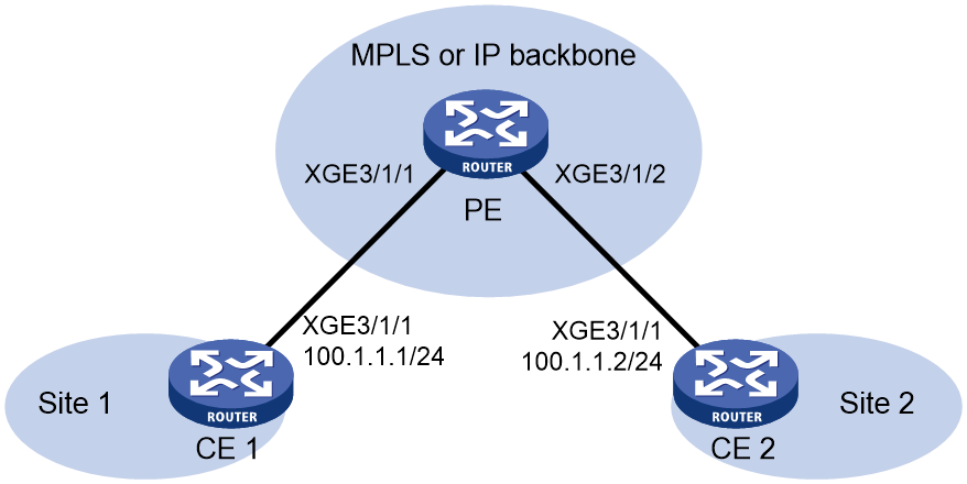
Network configuration
Configure local MPLS L2VPN connections between the PE and CEs to allow Layer 2 communication between CE 1 and CE 2.
Figure 11 Network diagram
Procedure
1. Configure CE 1.
<CE1> system-view
[CE1] interface ten-gigabitethernet 3/1/1
[CE1-Ten-GigabitEthernet3/1/1] ip address 100.1.1.1 24
[CE1-Ten-GigabitEthernet3/1/1] quit
2. Configure CE 2.
<CE2> system-view
[CE2] interface ten-gigabitethernet 3/1/1
[CE2-Ten-GigabitEthernet3/1/1] ip address 100.1.1.2 24
[CE2-Ten-GigabitEthernet3/1/1] quit
3. Configure PE:
# Enable L2VPN.
<PE> system-view
[PE] l2vpn enable
# Create a cross-connect group named vpn1, create a cross-connect named vpn1 in the group, and bind Ten-GigabitEthernet 3/1/1 and Ten-GigabitEthernet 3/1/2 to the cross-connect.
[PE] xconnect-group vpn1
[PE-xcg-vpn1] connection vpn1
[PE-xcg-vpn1-vpn1] ac interface ten-gigabitethernet 3/1/1
[PE-xcg-vpn1-vpn1-Ten-GigabitEthernet3/1/1] quit
[PE-xcg-vpn1-vpn1] ac interface ten-gigabitethernet 3/1/2
[PE-xcg-vpn1-vpn1-Ten-GigabitEthernet3/1/2] quit
[PE-xcg-vpn1-vpn1] quit
[PE-xcg-vpn1] quit
Verifying the configuration
# Verify that two AC forwarding entries exist on the PE.
[PE] display l2vpn forwarding ac
Total number of cross-connections: 1
Total number of ACs: 2
AC Xconnect-group Name Link ID
XGE3/1/1 vpn1 0
XGE3/1/2 vpn1 1
# Verify that CE 1 and CE 2 can ping each other. (Details not shown.)
Example: Configuring a static PW
Network configuration
Create a static PW between PE 1 and PE 2 over the backbone to allow communication between CE 1 and CE 2.
Figure 12 Network diagram

Table 2 Interface and IP address assignment
|
Device |
Interface |
IP address |
Device |
Interface |
IP address |
|
CE 1 |
XGE3/1/1 |
100.1.1.1/24 |
P |
Loop0 |
192.4.4.4/32 |
|
PE 1 |
Loop0 |
192.2.2.2/32 |
|
XGE3/1/1 |
10.1.1.2/24 |
|
|
XGE3/1/1 |
- |
|
XGE3/1/2 |
10.2.2.2/24 |
|
|
XGE3/1/2 |
10.1.1.1/24 |
PE 2 |
Loop0 |
192.3.3.3/32 |
|
CE 2 |
XGE3/1/1 |
100.1.1.2/24 |
|
XGE3/1/1 |
- |
|
|
|
|
|
XGE3/1/2 |
10.2.2.1/24 |
Procedure
1. Configure CE 1.
<CE1> system-view
[CE1] interface ten-gigabitethernet 3/1/1
[CE1-Ten-GigabitEthernet3/1/1] ip address 100.1.1.1 24
[CE1-Ten-GigabitEthernet3/1/1] quit
2. Configure PE 1:
# Configure an LSR ID.
<PE1> system-view
[PE1] interface loopback 0
[PE1-LoopBack0] ip address 192.2.2.2 32
[PE1-LoopBack0] quit
[PE1] mpls lsr-id 192.2.2.2
# Enable L2VPN.
[PE1] l2vpn enable
# Enable global LDP.
[PE1] mpls ldp
[PE1-ldp] quit
# Configure Ten-GigabitEthernet 3/1/2 (the interface connected to the P device), and enable LDP on the interface.
[PE1] interface ten-gigabitethernet 3/1/2
[PE1-Ten-GigabitEthernet3/1/2] ip address 10.1.1.1 24
[PE1-Ten-GigabitEthernet3/1/2] mpls enable
[PE1-Ten-GigabitEthernet3/1/2] mpls ldp enable
[PE1-Ten-GigabitEthernet3/1/2] quit
# Configure OSPF for LDP to create LSPs.
[PE1] ospf
[PE1-ospf-1] area 0
[PE1-ospf-1-area-0.0.0.0] network 10.1.1.1 0.0.0.255
[PE1-ospf-1-area-0.0.0.0] network 192.2.2.2 0.0.0.0
[PE1-ospf-1-area-0.0.0.0] quit
[PE1-ospf-1] quit
# Create a cross-connect group named vpna, create a cross-connect named svc in the group, and bind Ten-GigabitEthernet 3/1/1 to the cross-connect.
[PE1] xconnect-group vpna
[PE1-xcg-vpna] connection svc
[PE1-xcg-vpna-svc] ac interface ten-gigabitethernet 3/1/1
[PE1-xcg-vpna-svc-Ten-GigabitEthernet3/1/1] quit
# Create a static PW for the cross-connect to bind the AC to the PW.
[PE1-xcg-vpna-svc] peer 192.3.3.3 pw-id 3 in-label 100 out-label 200
[PE1-xcg-vpna-svc-192.3.3.3-3] quit
[PE1-xcg-vpna-svc] quit
[PE1-xcg-vpna] quit
3. Configure the P device:
# Configure an LSR ID.
<P> system-view
[P] interface loopback 0
[P-LoopBack0] ip address 192.4.4.4 32
[P-LoopBack0] quit
[P] mpls lsr-id 192.4.4.4
# Enable global LDP.
[P] mpls ldp
[P-ldp] quit
# Configure Ten-GigabitEthernet 3/1/1 (the interface connected to PE 1), and enable LDP on the interface.
[P] interface ten-gigabitethernet 3/1/1
[P-Ten-GigabitEthernet3/1/1] ip address 10.1.1.2 24
[P-Ten-GigabitEthernet3/1/1] mpls enable
[P-Ten-GigabitEthernet3/1/1] mpls ldp enable
[P-Ten-GigabitEthernet3/1/1] quit
# Configure Ten-GigabitEthernet 3/1/2 (the interface connected to PE 2), and enable LDP on the interface.
[P] interface ten-gigabitethernet 3/1/2
[P-Ten-GigabitEthernet3/1/2] ip address 10.2.2.2 24
[P-Ten-GigabitEthernet3/1/2] mpls enable
[P-Ten-GigabitEthernet3/1/2] mpls ldp enable
[P-Ten-GigabitEthernet3/1/2] quit
# Configure OSPF for LDP to create LSPs.
[P] ospf
[P-ospf-1] area 0
[P-ospf-1-area-0.0.0.0] network 10.1.1.2 0.0.0.255
[P-ospf-1-area-0.0.0.0] network 10.2.2.2 0.0.0.255
[P-ospf-1-area-0.0.0.0] network 192.4.4.4 0.0.0.0
[P-ospf-1-area-0.0.0.0] quit
[P-ospf-1] quit
4. Configure PE 2:
# Configure an LSR ID.
<PE2> system-view
[PE2] interface loopback 0
[PE2-LoopBack0] ip address 192.3.3.3 32
[PE2-LoopBack0] quit
[PE2] mpls lsr-id 192.3.3.3
# Enable L2VPN.
[PE2] l2vpn enable
# Enable globally LDP.
[PE2] mpls ldp
[PE2-ldp] quit
# Configure Ten-GigabitEthernet 3/1/2 (the interface connected to the P device), and enable LDP on the interface.
[PE2] interface ten-gigabitethernet 3/1/2
[PE2-Ten-GigabitEthernet3/1/2] ip address 10.2.2.1 24
[PE2-Ten-GigabitEthernet3/1/2] mpls enable
[PE2-Ten-GigabitEthernet3/1/2] mpls ldp enable
[PE2-Ten-GigabitEthernet3/1/2] quit
# Configure OSPF for LDP to create LSPs.
[PE2] ospf
[PE2-ospf-1] area 0
[PE2-ospf-1-area-0.0.0.0] network 10.2.2.1 0.0.0.255
[PE2-ospf-1-area-0.0.0.0] network 192.3.3.3 0.0.0.0
[PE2-ospf-1-area-0.0.0.0] quit
[PE2-ospf-1] quit
# Create a cross-connect group named vpna, create a cross-connect named svc in the group, and bind Ten-GigabitEthernet 3/1/1 to the cross-connect.
[PE2] xconnect-group vpna
[PE2-xcg-vpna] connection svc
[PE2-xcg-vpna-svc] ac interface ten-gigabitethernet 3/1/1
[PE2-xcg-vpna-svc-Ten-GigabitEthernet3/1/1] quit
# Create a static PW for the cross-connect to bind the AC to the PW.
[PE2-xcg-vpna-svc] peer 192.2.2.2 pw-id 3 in-label 200 out-label 100
[PE2-xcg-vpna-svc-192.2.2.2-3] quit
[PE2-xcg-vpna-svc] quit
[PE2-xcg-vpna] quit
5. Configure CE 2.
<CE2> system-view
[CE2] interface ten-gigabitethernet 3/1/1
[CE2-Ten-GigabitEthernet3/1/1] ip address 100.1.1.2 24
[CE2-Ten-GigabitEthernet3/1/1] quit
Verifying the configuration
# Verify that a static PW has been established on PE 1.
[PE1] display l2vpn pw
Flags: M - main, B - backup, E - ecmp, BY - bypass, H - hub link, S - spoke link
N - no split horizon, A - administration, ABY – ac-bypass
PBY – pw-bypass
Total number of PWs: 1
1 up, 0 blocked, 0 down, 0 defect, 0 idle, 0 duplicate
Xconnect-group Name: vpna
Peer PWID/RmtSite/SrvID In/Out Label Proto Flag Link ID State
192.3.3.3 3 100/200 Static M 0 Up
# Verify that a static PW has been established on PE 2.
[PE2] display l2vpn pw
Flags: M - main, B - backup, E - ecmp, BY - bypass, H - hub link, S - spoke link
N - no split horizon, A - administration, ABY – ac-bypass
PBY – pw-bypass
Total number of PWs: 1
1 up, 0 blocked, 0 down, 0 defect, 0 idle, 0 duplicate
Xconnect-group Name: vpna
Peer PWID/RmtSite/SrvID In/Out Label Proto Flag Link ID State
192.2.2.2 3 200/100 Static M Up
# Verify that CE 1 and CE 2 can ping each other. (Details not shown.)
Example: Configuring an LDP PW
Network configuration
Create an LDP PW between PE 1 and PE 2 over the backbone to allow communication between CE 1 and CE 2.
Figure 13 Network diagram
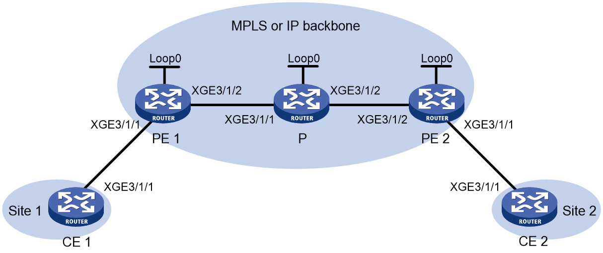
Table 3 Interface and IP address assignment
|
Device |
Interface |
IP address |
Device |
Interface |
IP address |
|
CE 1 |
XGE3/1/1 |
100.1.1.1/24 |
P |
Loop0 |
192.4.4.4/32 |
|
PE 1 |
Loop0 |
192.2.2.2/32 |
|
XGE3/1/1 |
10.1.1.2/24 |
|
|
XGE3/1/1 |
- |
|
XGE3/1/2 |
10.2.2.2/24 |
|
|
XGE3/1/2 |
10.1.1.1/24 |
PE 2 |
Loop0 |
192.3.3.3/32 |
|
CE 2 |
XGE3/1/1 |
100.1.1.2/24 |
|
XGE3/1/1 |
- |
|
|
|
|
|
XGE3/1/2 |
10.2.2.1/24 |
Procedure
1. Configure CE 1.
<CE1> system-view
[CE1] interface ten-gigabitethernet 3/1/1
[CE1-Ten-GigabitEthernet3/1/1] ip address 100.1.1.1 24
[CE1-Ten-GigabitEthernet3/1/1] quit
2. Configure PE 1:
# Configure an LSR ID.
<PE1> system-view
[PE1] interface loopback 0
[PE1-LoopBack0] ip address 192.2.2.2 32
[PE1-LoopBack0] quit
[PE1] mpls lsr-id 192.2.2.2
# Enable L2VPN.
[PE1] l2vpn enable
# Enable global LDP.
[PE1] mpls ldp
[PE1-ldp] quit
# Configure Ten-GigabitEthernet 3/1/2 (the interface connected to the P device), and enable LDP on the interface.
[PE1] interface ten-gigabitethernet 3/1/2
[PE1-Ten-GigabitEthernet3/1/2] ip address 10.1.1.1 24
[PE1-Ten-GigabitEthernet3/1/2] mpls enable
[PE1-Ten-GigabitEthernet3/1/2] mpls ldp enable
[PE1-Ten-GigabitEthernet3/1/2] quit
# Configure OSPF for LDP to create LSPs.
[PE1] ospf
[PE1-ospf-1] area 0
[PE1-ospf-1-area-0.0.0.0] network 10.1.1.1 0.0.0.255
[PE1-ospf-1-area-0.0.0.0] network 192.2.2.2 0.0.0.0
[PE1-ospf-1-area-0.0.0.0] quit
[PE1-ospf-1] quit
# Create a cross-connect group named vpna, create a cross-connect named ldp in the group, and bind Ten-GigabitEthernet 3/1/1 to the cross-connect.
[PE1] xconnect-group vpna
[PE1-xcg-vpna] connection ldp
[PE1-xcg-vpna-ldp] ac interface ten-gigabitethernet 3/1/1
[PE1-xcg-vpna-ldp-Ten-GigabitEthernet3/1/1] quit
# Create an LDP PW for the cross-connect to bind the AC to the PW.
[PE1-xcg-vpna-ldp] peer 192.3.3.3 pw-id 3
[PE1-xcg-vpna-ldp-192.3.3.3-3] quit
[PE1-xcg-vpna-ldp] quit
[PE1-xcg-vpna] quit
3. Configure the P device:
# Configure an LSR ID.
<P> system-view
[P] interface loopback 0
[P-LoopBack0] ip address 192.4.4.4 32
[P-LoopBack0] quit
[P] mpls lsr-id 192.4.4.4
# Enable global LDP.
[P] mpls ldp
[P-ldp] quit
# Configure Ten-GigabitEthernet 3/1/1 (the interface connected to PE 1), and enable LDP on the interface.
[P] interface ten-gigabitethernet 3/1/1
[P-Ten-GigabitEthernet3/1/1] ip address 10.1.1.2 24
[P-Ten-GigabitEthernet3/1/1] mpls enable
[P-Ten-GigabitEthernet3/1/1] mpls ldp enable
[P-Ten-GigabitEthernet3/1/1] quit
# Configure Ten-GigabitEthernet 3/1/2 (the interface connected to PE 2), and enable LDP on the interface.
[P] interface ten-gigabitethernet 3/1/2
[P-Ten-GigabitEthernet3/1/2] ip address 10.2.2.2 24
[P-Ten-GigabitEthernet3/1/2] mpls enable
[P-Ten-GigabitEthernet3/1/2] mpls ldp enable
[P-Ten-GigabitEthernet3/1/2] quit
# Configure OSPF for LDP to create LSPs.
[P] ospf
[P-ospf-1] area 0
[P-ospf-1-area-0.0.0.0] network 10.1.1.2 0.0.0.255
[P-ospf-1-area-0.0.0.0] network 10.2.2.2 0.0.0.255
[P-ospf-1-area-0.0.0.0] network 192.4.4.4 0.0.0.0
[P-ospf-1-area-0.0.0.0] quit
[P-ospf-1] quit
4. Configure PE 2:
# Configure an LSR ID.
<PE2> system-view
[PE2] interface loopback 0
[PE2-LoopBack0] ip address 192.3.3.3 32
[PE2-LoopBack0] quit
[PE2] mpls lsr-id 192.3.3.3
# Enable L2VPN.
[PE2] l2vpn enable
# Enable global LDP.
[PE2] mpls ldp
[PE2-ldp] quit
# Configure Ten-GigabitEthernet 3/1/2 (the interface connected to the P device), and enable LDP on the interface.
[PE2] interface ten-gigabitethernet 3/1/2
[PE2-Ten-GigabitEthernet3/1/2] ip address 10.2.2.1 24
[PE2-Ten-GigabitEthernet3/1/2] mpls enable
[PE2-Ten-GigabitEthernet3/1/2] mpls ldp enable
[PE2-Ten-GigabitEthernet3/1/2] quit
# Configure OSPF for LDP to create LSPs.
[PE2] ospf
[PE2-ospf-1] area 0
[PE2-ospf-1-area-0.0.0.0] network 192.3.3.3 0.0.0.0
[PE2-ospf-1-area-0.0.0.0] network 10.2.2.0 0.0.0.255
[PE2-ospf-1-area-0.0.0.0] quit
[PE2-ospf-1] quit
# Create a cross-connect group named vpna, create a cross-connect named ldp in the group, and bind Ten-GigabitEthernet 3/1/1 to the cross-connect.
[PE2] xconnect-group vpna
[PE2-xcg-vpna] connection ldp
[PE2-xcg-vpna-ldp] ac interface ten-gigabitethernet 3/1/1
[PE2-xcg-vpna-ldp-Ten-GigabitEthernet3/1/1] quit
# Create an LDP PW for the cross-connect to bind the AC to the PW.
[PE2-xcg-vpna-ldp] peer 192.2.2.2 pw-id 3
[PE2-xcg-vpna-ldp-192.2.2.2-3] quit
[PE2-xcg-vpna-ldp] quit
[PE2-xcg-vpna] quit
5. Configure CE 2.
<CE2> system-view
[CE2] interface ten-gigabitethernet 3/1/1
[CE2-Ten-GigabitEthernet3/1/1] ip address 100.1.1.2 24
[CE2-Ten-GigabitEthernet3/1/1] quit
Verifying the configuration
# Verify that an LDP PW has been established on PE 1.
[PE1] display l2vpn pw
Flags: M - main, B - backup, E - ecmp, BY - bypass, H - hub link, S - spoke link
N - no split horizon, A - administration, ABY – ac-bypass
PBY – pw-bypass
Total number of PWs: 1
1 up, 0 blocked, 0 down, 0 defect, 0 idle, 0 duplicate
Xconnect-group Name: vpna
Peer PWID/RmtSite/SrvID In/Out Label Proto Flag Link ID State
192.3.3.3 3 1279/1279 LDP M 1 Up
# Verify that an LDP PW has been established on PE 2.
[PE2] display l2vpn pw
Flags: M - main, B - backup, E - ecmp, BY - bypass, H - hub link, S - spoke link
N - no split horizon, A - administration, ABY – ac-bypass
PBY – pw-bypass
Total number of PWs: 1
1 up, 0 blocked, 0 down, 0 defect, 0 idle, 0 duplicate
Xconnect-group Name: vpna
Peer PWID/RmtSite/SrvID In/Out Label Proto Flag Link ID State
192.2.2.2 3 1279/1279 LDP M 1 Up
# Verify that CE 1 and CE 2 can ping each other. (Details not shown.)
Example: Configuring a BGP PW
Network configuration
Create a BGP PW between PE 1 and PE 2 to allow communication between CE 1 and CE 2.
Figure 14 Network diagram

Table 4 Interface and IP address assignment
|
Device |
Interface |
IP address |
Device |
Interface |
IP address |
|
CE 1 |
XGE3/1/1 |
100.1.1.1/24 |
P |
Loop0 |
192.4.4.4/32 |
|
PE 1 |
Loop0 |
192.2.2.2/32 |
|
XGE3/1/1 |
10.1.1.2/24 |
|
|
XGE3/1/1 |
- |
|
XGE3/1/2 |
10.2.2.2/24 |
|
|
XGE3/1/2 |
10.1.1.1/24 |
PE 2 |
Loop0 |
192.3.3.3/32 |
|
CE 2 |
XGE3/1/1 |
100.1.1.2/24 |
|
XGE3/1/1 |
- |
|
|
|
|
|
XGE3/1/2 |
10.2.2.1/24 |
Procedure
1. Configure CE 1.
<CE1> system-view
[CE1] interface ten-gigabitethernet 3/1/1
[CE1-Ten-GigabitEthernet3/1/1] ip address 100.1.1.1 24
[CE1-Ten-GigabitEthernet3/1/1] quit
2. Configure PE 1:
# Configure an LSR ID.
<PE1> system-view
[PE1] interface loopback 0
[PE1-LoopBack0] ip address 192.2.2.2 32
[PE1-LoopBack0] quit
[PE1] mpls lsr-id 192.2.2.2
# Enable L2VPN.
[PE1] l2vpn enable
# Enable global LDP.
[PE1] mpls ldp
[PE1-ldp] quit
# Configure Ten-GigabitEthernet 3/1/2 (the interface connected to the P device), and enable LDP on the interface.
[PE1] interface ten-gigabitethernet 3/1/2
[PE1-Ten-GigabitEthernet3/1/2] ip address 10.1.1.1 24
[PE1-Ten-GigabitEthernet3/1/2] mpls enable
[PE1-Ten-GigabitEthernet3/1/2] mpls ldp enable
[PE1-Ten-GigabitEthernet3/1/2] quit
# Configure OSPF for LDP to create LSPs.
[PE1] ospf
[PE1-ospf-1] area 0
[PE1-ospf-1-area-0.0.0.0] network 10.1.1.1 0.0.0.255
[PE1-ospf-1-area-0.0.0.0] network 192.2.2.2 0.0.0.0
[PE1-ospf-1-area-0.0.0.0] quit
[PE1-ospf-1] quit
# Create an IBGP connection to PE 2, and enable BGP to advertise L2VPN information to PE 2.
[PE1] bgp 100
[PE1-bgp-default] peer 192.3.3.3 as-number 100
[PE1-bgp-default] peer 192.3.3.3 connect-interface loopback 0
[PE1-bgp-default] address-family l2vpn
[PE1-bgp-default-l2vpn] peer 192.3.3.3 enable
[PE1-bgp-default-l2vpn] quit
[PE1-bgp-default] quit
# Create a cross-connect group named vpnb, create a local site named site 1, and create a BGP PW from site 1 to remote site site 2.
[PE1] xconnect-group vpnb
[PE1-xcg-vpnb] auto-discovery bgp
[PE1-xcg-vpnb-auto] route-distinguisher 2:2
[PE1-xcg-vpnb-auto] vpn-target 2:2 export-extcommunity
[PE1-xcg-vpnb-auto] vpn-target 2:2 import-extcommunity
[PE1-xcg-vpnb-auto] site 1 range 10 default-offset 0
[PE1-xcg-vpnb-auto-1] connection remote-site-id 2
# Bind Ten-GigabitEthernet 3/1/1 to the PW.
[PE1-xcg-vpnb-auto-1-2] ac interface ten-gigabitethernet 3/1/1
[PE1-xcg-vpnb-auto-1-2] return
3. Configure the P device:
# Configure an LSR ID.
<P> system-view
[P] interface loopback 0
[P-LoopBack0] ip address 192.4.4.4 32
[P-LoopBack0] quit
[P] mpls lsr-id 192.4.4.4
# Enable global LDP.
[P] mpls ldp
[P-ldp] quit
# Configure Ten-GigabitEthernet 3/1/1 (the interface connected to PE 1), and enable LDP on the interface.
[P] interface ten-gigabitethernet 3/1/1
[P-Ten-GigabitEthernet3/1/1] ip address 10.1.1.2 24
[P-Ten-GigabitEthernet3/1/1] mpls enable
[P-Ten-GigabitEthernet3/1/1] mpls ldp enable
[P-Ten-GigabitEthernet3/1/1] quit
# Configure Ten-GigabitEthernet 3/1/2 (the interface connected to PE 2), and enable LDP on the interface.
[P] interface ten-gigabitethernet 3/1/2
[P-Ten-GigabitEthernet3/1/2] ip address 10.2.2.2 24
[P-Ten-GigabitEthernet3/1/2] mpls enable
[P-Ten-GigabitEthernet3/1/2] mpls ldp enable
[P-Ten-GigabitEthernet3/1/2] quit
# Configure OSPF for LDP to create LSPs.
[P] ospf
[P-ospf-1] area 0
[P-ospf-1-area-0.0.0.0] network 10.1.1.2 0.0.0.255
[P-ospf-1-area-0.0.0.0] network 10.2.2.2 0.0.0.255
[P-ospf-1-area-0.0.0.0] network 192.4.4.4 0.0.0.0
[P-ospf-1-area-0.0.0.0] quit
[P-ospf-1] quit
4. Configure PE 2:
# Configure an LSR ID.
<PE2> system-view
[PE2] interface loopback 0
[PE2-LoopBack0] ip address 192.3.3.3 32
[PE2-LoopBack0] quit
[PE2] mpls lsr-id 192.3.3.3
# Enable L2VPN.
[PE2] l2vpn enable
# Enable global LDP.
[PE2] mpls ldp
[PE2-ldp] quit
# Configure Ten-GigabitEthernet 3/1/2 (the interface connected to the P device), and enable LDP on the interface.
[PE2] interface ten-gigabitethernet 3/1/2
[PE2-Ten-GigabitEthernet3/1/2] ip address 10.2.2.1 24
[PE2-Ten-GigabitEthernet3/1/2] mpls enable
[PE2-Ten-GigabitEthernet3/1/2] mpls ldp enable
[PE2-Ten-GigabitEthernet3/1/2] quit
# Configure OSPF for LDP to create LSPs.
[PE2] ospf
[PE2-ospf-1] area 0
[PE2-ospf-1-area-0.0.0.0] network 192.3.3.3 0.0.0.0
[PE2-ospf-1-area-0.0.0.0] network 10.2.2.0 0.0.0.255
[PE2-ospf-1-area-0.0.0.0] quit
[PE2-ospf-1] quit
# Create an IBGP connection to PE 1, and enable BGP to advertise L2VPN information to PE 1.
[PE2] bgp 100
[PE2-bgp-default] peer 192.2.2.2 as-number 100
[PE2-bgp-default] peer 192.2.2.2 connect-interface loopback 0
[PE2-bgp-default] address-family l2vpn
[PE2-bgp-default-l2vpn] peer 192.2.2.2 enable
[PE2-bgp-default-l2vpn] quit
[PE2-bgp-default] quit
# Create a cross-connect group named vpnb, create a local site named site 2, and create a BGP PW from site 2 to remote site site 1.
[PE2] xconnect-group vpnb
[PE2-xcg-vpnb] auto-discovery bgp
[PE2-xcg-vpnb-auto] route-distinguisher 2:2
[PE2-xcg-vpnb-auto] vpn-target 2:2 export-extcommunity
[PE2-xcg-vpnb-auto] vpn-target 2:2 import-extcommunity
[PE2-xcg-vpnb-auto] site 2 range 10 default-offset 0
[PE2-xcg-vpnb-auto-2] connection remote-site-id 1
# Bind Ten-GigabitEthernet 3/1/1 to the PW.
[PE2-xcg-vpnb-auto-2-1] ac interface ten-gigabitethernet 3/1/1
[PE2-xcg-vpnb-auto-2-1] return
5. Configure CE 2.
<CE2> system-view
[CE2] interface ten-gigabitethernet 3/1/1
[CE2-Ten-GigabitEthernet3/1/1] ip address 100.1.1.2 24
[CE2-Ten-GigabitEthernet3/1/1] quit
Verifying the configuration
# Verify that a BGP PW has been established on PE 1.
<PE1> display l2vpn pw
Flags: M - main, B - backup, E - ecmp, BY - bypass, H - hub link, S - spoke link
N - no split horizon, A - administration, ABY – ac-bypass
PBY – pw-bypass
Total number of PWs: 1
1 up, 0 blocked, 0 down, 0 defect, 0 idle, 0 duplicate
Xconnect-group Name: vpnb
Peer PWID/RmtSite/SrvID In/Out Label Proto Flag Link ID State
192.3.3.3 2 1036/1025 BGP M 1 Up
# Verify that a BGP PW has been established on PE 2.
<PE2> display l2vpn pw
Flags: M - main, B - backup, E - ecmp, BY - bypass, H - hub link, S - spoke link
N - no split horizon, A - administration, ABY – ac-bypass
PBY – pw-bypass
Total number of PWs: 1
1 up, 0 blocked, 0 down, 0 defect, 0 idle, 0 duplicate
Xconnect-group Name: vpnb
Peer PWID/RmtSite/SrvID In/Out Label Proto Flag Link ID State
192.2.2.2 1 1025/1036 BGP M 1 Up
# Verify that CE 1 and CE 2 can ping each other. (Details not shown.)
Example: Configuring a bypass PW
Network configuration
Create two LDP PWs to implement PW redundancy between CE 1 and CE 2. The primary PW goes through PE 1—PE 2. The backup PW goes through PE 1—PE 3. When the primary PW fails, CE 1 and CE 2 communicate through the backup PW.
Create a bypass PW between PE 2 and PE 3 to forward traffic when a primary/backup PW switchover occurs.
Figure 15 Network diagram
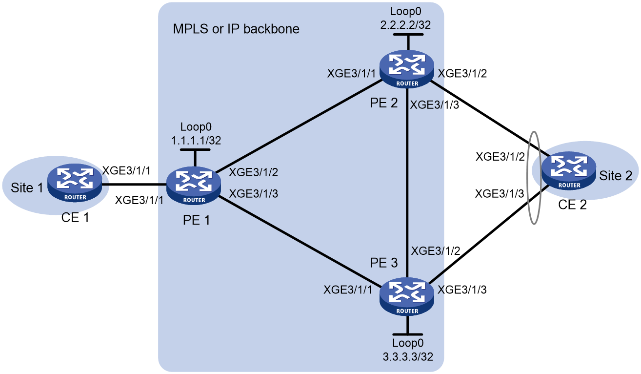
Table 5 Interface and IP address assignment
|
Device |
Interface |
IP address |
Device |
Interface |
IP address |
|
CE 1 |
XGE3/1/1 |
192.1.1.1/24 |
PE 2 |
Loop0 |
2.2.2.2/32 |
|
PE 1 |
Loop0 |
1.1.1.1/32 |
|
XGE3/1/1 |
10.1.1.2/24 |
|
|
XGE3/1/2 |
10.1.1.1/24 |
|
XGE3/1/3 |
10.1.3.1/24 |
|
|
XGE3/1/3 |
10.1.2.1/24 |
PE 3 |
Loop0 |
3.3.3.3/32 |
|
CE 2 |
RAGG1 |
192.1.1.2/24 |
|
XGE3/1/1 |
10.1.2.2/24 |
Procedure
1. Configure CE 1.
<CE1> system-view
[CE1] interface ten-gigabitethernet 3/1/1
[CE1-Ten-GigabitEthernet3/1/1] ip address 192.1.1.1 24
[CE1-Ten-GigabitEthernet3/1/1] quit
2. Configure PE 1:
# Configure an LSR ID.
<PE1> system-view
[PE1] interface loopback 0
[PE1-LoopBack0] ip address 1.1.1.1 32
[PE1-LoopBack0] quit
[PE1] mpls lsr-id 1.1.1.1
# Enable L2VPN.
[PE1] l2vpn enable
# Enable global LDP.
[PE1] mpls ldp
[PE1-ldp] quit
# Configure Ten-GigabitEthernet 3/1/2 (the interface connected to PE 2), and enable MPLS and LDP on the interface.
[PE1] interface ten-gigabitethernet 3/1/2
[PE1-Ten-GigabitEthernet3/1/2] ip address 10.1.1.1 24
[PE1-Ten-GigabitEthernet3/1/2] mpls enable
[PE1-Ten-GigabitEthernet3/1/2] mpls ldp enable
[PE1-Ten-GigabitEthernet3/1/2] quit
# Configure Ten-GigabitEthernet 3/1/3 (the interface connected to PE 3), and enable MPLS and LDP on the interface.
[PE1] interface ten-gigabitethernet 3/1/3
[PE1-Ten-GigabitEthernet3/1/3] ip address 10.1.2.1 24
[PE1-Ten-GigabitEthernet3/1/3] mpls enable
[PE1-Ten-GigabitEthernet3/1/3] mpls ldp enable
[PE1-Ten-GigabitEthernet3/1/3] quit
# Configure OSPF for LDP to create LSPs.
[PE1] ospf
[PE1-ospf-1] area 0
[PE1-ospf-1-area-0.0.0.0] network 10.1.1.1 0.0.0.255
[PE1-ospf-1-area-0.0.0.0] network 10.1.2.1 0.0.0.255
[PE1-ospf-1-area-0.0.0.0] network 1.1.1.1 0.0.0.0
[PE1-ospf-1-area-0.0.0.0] quit
[PE1-ospf-1] quit
# Create a cross-connect group named vpna, create a cross-connect named ldp in the group, and bind Ten-GigabitEthernet 3/1/1 to the cross-connect.
[PE1] xconnect-group vpna
[PE1-xcg-vpna] connection ldp
[PE1-xcg-vpna-ldp] ac interface Ten-GigabitEthernet 3/1/1
[PE1-xcg-vpna-ldp-Ten-GigabitEthernet3/1/1] quit
# Create an LDP PW for the cross-connect to bind the AC to the PW, create a backup PW for the LDP PW, and enable the dual receive feature for PW redundancy.
[PE1-xcg-vpna-ldp] protection dual-receive
[PE1-xcg-vpna-ldp] peer 2.2.2.2 pw-id 11
[PE1-xcg-vpna-ldp-2.2.2.2-11] backup-peer 3.3.3.3 pw-id 22
[PE1-xcg-vpna-ldp-2.2.2.2-11-backup] quit
[PE1-xcg-vpna-ldp-2.2.2.2-11] quit
[PE1-xcg-vpna-ldp] quit
[PE1-xcg-vpna] quit
3. Configure CE 2:
# Create Layer 3 aggregate interface Route-Aggregation 1, use the static aggregation mode (the default), and configure the IP address and subnet mask for the aggregate interface.
<CE2> system-view
[CE2] interface route-aggregation 1
[CE2-Route-Aggregation1] ip address 192.1.1.2 24
[CE2-Route-Aggregation1] quit
# Add interfaces Ten-GigabitEthernet 3/1/2 and Ten-GigabitEthernet 3/1/3 to Layer 3 aggregation group 1.
[CE2] interface ten-gigabitethernet 3/1/2
[CE2-Ten-GigabitEthernet3/1/2] port link-aggregation group 1
[CE2-Ten-GigabitEthernet3/1/2] quit
[CE2] interface ten-gigabitethernet 3/1/3
[CE2-Ten-GigabitEthernet3/1/3] port link-aggregation group 1
[CE2-Ten-GigabitEthernet3/1/3] quit
4. Configure PE 2:
# Configure an LSR ID.
<PE2> system-view
[PE2] interface loopback 0
[PE2-LoopBack0] ip address 2.2.2.2 32
[PE2-LoopBack0] quit
[PE2] mpls lsr-id 2.2.2.2
# Enable L2VPN.
[PE2] l2vpn enable
# Enable global LDP.
[PE2] mpls ldp
[PE2-ldp] quit
# Configure Ten-GigabitEthernet 3/1/1 (the interface connected to PE 1), and enable MPLS and LDP on the interface.
[PE2] interface ten-gigabitethernet 3/1/1
[PE2-Ten-GigabitEthernet3/1/1] ip address 10.1.1.2 24
[PE2-Ten-GigabitEthernet3/1/1] mpls enable
[PE2-Ten-GigabitEthernet3/1/1] mpls ldp enable
[PE2-Ten-GigabitEthernet3/1/1] quit
# Configure Ten-GigabitEthernet 3/1/3 (the interface connected to PE 3), and enable MPLS and LDP on the interface.
[PE2] interface ten-gigabitethernet 3/1/3
[PE2-Ten-GigabitEthernet3/1/3] ip address 10.1.3.1 24
[PE2-Ten-GigabitEthernet3/1/3] mpls enable
[PE2-Ten-GigabitEthernet3/1/3] mpls ldp enable
[PE2-Ten-GigabitEthernet3/1/3] quit
# Configure OSPF for LDP to create LSPs.
[PE2] ospf
[PE2-ospf-1] area 0
[PE2-ospf-1-area-0.0.0.0] network 10.1.1.2 0.0.0.255
[PE2-ospf-1-area-0.0.0.0] network 10.1.3.1 0.0.0.255
[PE2-ospf-1-area-0.0.0.0] network 2.2.2.2 0.0.0.0
[PE2-ospf-1-area-0.0.0.0] quit
[PE2-ospf-1] quit
# Create a cross-connect group named vpna, create a cross-connect named ldp in the group, and bind Ten-GigabitEthernet 3/1/2 to the cross-connect.
[PE2] xconnect-group vpna
[PE2-xcg-vpna] connection ldp
[PE2-xcg-vpna-ldp] ac interface ten-gigabitethernet 3/1/2
[PE2-xcg-vpna-ldp-Ten-GigabitEthernet3/1/2] quit
# Create an LDP PW for the cross-connect to bind the AC to the PW, and create a bypass PW for the LDP PW.
[PE2-xcg-vpna-ldp] peer 1.1.1.1 pw-id 11
[PE2-xcg-vpna-ldp-1.1.1.1-11] bypass-peer 3.3.3.3 pw-id 33
[PE2-xcg-vpna-ldp-1.1.1.1-11-bypass] quit
[PE2-xcg-vpna-ldp-1.1.1.1-11] quit
[PE2-xcg-vpna-ldp] quit
[PE2-xcg-vpna] quit
5. Configure PE 3:
# Configure an LSR ID.
<PE3> system-view
[PE3] interface loopback 0
[PE3-LoopBack0] ip address 3.3.3.3 32
[PE3-LoopBack0] quit
[PE3] mpls lsr-id 3.3.3.3
# Enable L2VPN.
[PE3] l2vpn enable
# Enable global LDP.
[PE3] mpls ldp
[PE3-ldp] quit
# Configure Ten-GigabitEthernet 3/1/1 (the interface connected to PE 1), and enable MPLS and LDP on the interface.
[PE3] interface ten-gigabitethernet 3/1/1
[PE3-Ten-GigabitEthernet3/1/1] ip address 10.1.2.2 24
[PE3-Ten-GigabitEthernet3/1/1] mpls enable
[PE3-Ten-GigabitEthernet3/1/1] mpls ldp enable
[PE3-Ten-GigabitEthernet3/1/1] quit
# Configure Ten-GigabitEthernet 3/1/2 (the interface connected to PE 2), and enable MPLS and LDP on the interface.
[PE3] interface ten-gigabitethernet 3/1/2
[PE3-Ten-GigabitEthernet3/1/2] ip address 10.1.3.2 24
[PE3-Ten-GigabitEthernet3/1/2] mpls enable
[PE3-Ten-GigabitEthernet3/1/2] mpls ldp enable
[PE3-Ten-GigabitEthernet3/1/2] quit
# Configure OSPF for LDP to create LSPs.
[PE3] ospf
[PE3-ospf-1] area 0
[PE3-ospf-1-area-0.0.0.0] network 10.1.2.2 0.0.0.255
[PE3-ospf-1-area-0.0.0.0] network 10.1.3.2 0.0.0.255
[PE3-ospf-1-area-0.0.0.0] network 3.3.3.3 0.0.0.0
[PE3-ospf-1-area-0.0.0.0] quit
[PE3-ospf-1] quit
# Create a cross-connect group named vpna, create a cross-connect named ldp in the group, and bind Ten-GigabitEthernet 3/1/3 to the cross-connect.
[PE3] xconnect-group vpna
[PE3-xcg-vpna] connection ldp
[PE3-xcg-vpna-ldp] ac interface ten-gigabitethernet 3/1/3
[PE3-xcg-vpna-ldp-Ten-GigabitEthernet3/1/3] quit
# Create an LDP PW for the cross-connect to bind the AC to the PW, and create a bypass PW for the LDP PW.
[PE3-xcg-vpna-ldp] peer 1.1.1.1 pw-id 22
[PE3-xcg-vpna-ldp-1.1.1.1-22] bypass-peer 2.2.2.2 pw-id 33
[PE3-xcg-vpna-ldp-1.1.1.1-22-bypass] quit
[PE3-xcg-vpna-ldp-1.1.1.1-22] quit
[PE3-xcg-vpna-ldp] quit
[PE3-xcg-vpna] quit
Example: Configuring an intra-domain multi-segment PW
Network configuration
As shown in Figure 16, there is no public tunnel between PE 1 and PE 2. There is an MPLS TE tunnel between PE 1 and P, and an MPLS TE tunnel between P and PE 2.
Configure a multi-segment PW within the backbone to allow communication between CE 1 and CE 2. The multi-segment PW includes an LDP PW between PE 1 and P, and a static PW between P and PE 2. The two PWs are concatenated on P.
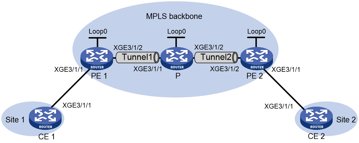
Table 6 Interface and IP address assignment
|
Device |
Interface |
IP address |
Device |
Interface |
IP address |
|
CE 1 |
XGE3/1/1 |
100.1.1.1/24 |
P |
Loop0 |
192.4.4.4/32 |
|
PE 1 |
Loop0 |
192.2.2.2/32 |
|
XGE3/1/1 |
23.1.1.2/24 |
|
|
XGE3/1/2 |
23.1.1.1/24 |
|
XGE3/1/2 |
26.2.2.2/24 |
|
CE 2 |
XGE3/1/1 |
100.1.1.2/24 |
PE 2 |
Loop0 |
192.3.3.3/32 |
|
|
|
|
|
XGE3/1/2 |
26.2.2.1/24 |
Procedure
1. Configure CE 1.
<CE1> system-view
[CE1] interface ten-gigabitethernet 3/1/1
[CE1-Ten-GigabitEthernet3/1/1] ip address 100.1.1.1 24
[CE1-Ten-GigabitEthernet3/1/1] quit
2. Configure PE 1:
# Configure an LSR ID.
<PE1> system-view
[PE1] interface loopback 0
[PE1-LoopBack0] ip address 192.2.2.2 32
[PE1-LoopBack0] quit
[PE1] mpls lsr-id 192.2.2.2
# Enable L2VPN.
[PE1] l2vpn enable
# Enable LDP globally.
[PE1] mpls ldp
[PE1-ldp] quit
# Configure MPLS TE to establish an MPLS TE tunnel between PE 1 and P. For more information, see "Configuring MPLS TE."
# Create a cross-connect group named vpn1, create a cross-connect named ldp in the group, and bind Ten-GigabitEthernet 3/1/1 to the cross-connect.
[PE1] xconnect-group vpn1
[PE1-xcg-vpn1] connection ldp
[PE1-xcg-vpn1-ldp] ac interface ten-gigabitethernet 3/1/1
[PE1-xcg-vpn1-ldp-Ten-GigabitEthernet3/1/1] quit
# Create an LDP PW for the cross-connect to bind the AC to the PW.
[PE1-xcg-vpn1-ldp] peer 192.4.4.4 pw-id 1000
[PE1-xcg-vpn1-ldp-192.4.4.4-1000] quit
[PE1-xcg-vpn1-ldp] quit
[PE1-xcg-vpn1] quit
3. Configure the P device:
# Configure an LSR ID.
<P> system-view
[P] interface loopback 0
[P-LoopBack0] ip address 192.4.4.4 32
[P-LoopBack0] quit
[P] mpls lsr-id 192.4.4.4
# Enable L2VPN.
[P] l2vpn enable
# Enable LDP globally.
[P] mpls ldp
[P-ldp] quit
# Create a PW class named pwa, and configure the PW data encapsulation type as ethernet.
[P] pw-class pwa
[P-pw-class-pwa] pw-type ethernet
[P-pw-class-pwa] quit
# Configure MPLS TE to establish an MPLS TE tunnel between PE 1 and P, and between P and PE 2. For more information, see "Configuring MPLS TE."
# Create a cross-connect group named vpn1, create a cross-connect named ldpsvc in the group, and create an LDP PW and a static PW for the cross-connect to form a multi-segment PW.
[P] xconnect-group vpn1
[P-xcg-vpn1] connection ldpsvc
[P-xcg-vpn1-ldpsvc] peer 192.2.2.2 pw-id 1000 pw-class pwa
[P-xcg-vpn1-ldpsvc-192.2.2.2-1000] quit
[P-xcg-vpn1-ldpsvc] peer 192.3.3.3 pw-id 1000 in-label 100 out-label 200 pw-class pwa
[P-xcg-vpn1-ldpsvc-192.3.3.3-1000] quit
[P-xcg-vpn1-ldpsvc] quit
[P-xcg-vpn1] quit
4. Configure PE 2:
# Configure an LSR ID.
<PE2> system-view
[PE2] interface loopback 0
[PE2-LoopBack0] ip address 192.3.3.3 32
[PE2-LoopBack0] quit
[PE2] mpls lsr-id 192.3.3.3
# Enable L2VPN.
[PE2] l2vpn enable
# Configure MPLS TE to establish an MPLS TE tunnel between P and PE 2. For more information, see "Configuring MPLS TE."
# Create a cross-connect group named vpn1, create a cross-connect named svc in the group, and bind Ten-GigabitEthernet 3/1/1 to the cross-connect.
[PE2] xconnect-group vpn1
[PE2-xcg-vpn1] connection svc
[PE2-xcg-vpn1-svc] ac interface ten-gigabitethernet 3/1/1
[PE2-xcg-vpn1-svc-Ten-GigabitEthernet3/1/1] quit
# Create a static PW for the cross-connect to bind the AC to the PW.
[PE2-xcg-vpn1-svc] peer 192.4.4.4 pw-id 1000 in-label 200 out-label 100
[PE2-xcg-vpn1-svc-192.4.4.4-1000] quit
[PE2-xcg-vpn1-svc] quit
[PE2-xcg-vpn1] quit
5. Configure CE 2.
<CE2> system-view
[CE2] interface ten-gigabitethernet 3/1/1
[CE2-Ten-GigabitEthernet3/1/1] ip address 100.1.1.2 24
[CE2-Ten-GigabitEthernet3/1/1] quit
Verifying the configuration
# Verify that two PWs have been created to form a multi-segment PW on the P device.
[P] display l2vpn pw
Flags: M - main, B - backup, E - ecmp, BY - bypass, H - hub link, S - spoke link
N - no split horizon, A - administration, ABY – ac-bypass
PBY – pw-bypass
Total number of PWs: 2
2 up, 0 blocked, 0 down, 0 defect, 0 idle, 0 duplicate
Xconnect-group Name: vpn1
Peer PWID/RmtSite/SrvID In/Out Label Proto Flag Link ID State
192.2.2.2 1000 1279/1150 LDP M 0 Up
192.3.3.3 1000 100/200 Static M 1 Up
# Verify that a PW has been created on PE 1.
[PE1] display l2vpn pw
Flags: M - main, B - backup, E - ecmp, BY - bypass, H - hub link, S - spoke link
N - no split horizon, A - administration, ABY – ac-bypass
PBY – pw-bypass
Total number of PWs: 1
1 up, 0 blocked, 0 down, 0 defect, 0 idle, 0 duplicate
Xconnect-group Name: vpn1
Peer PWID/RmtSite/SrvID In/Out Label Proto Flag Link ID State
192.4.4.4 1000 1150/1279 LDP M 1 Up
# Verify that a PW has been created on PE 2.
[PE2] display l2vpn pw
Flags: M - main, B - backup, E - ecmp, BY - bypass, H - hub link, S - spoke link
N - no split horizon, A - administration, ABY – ac-bypass
PBY – pw-bypass
Total number of PWs: 1
1 up, 0 blocked, 0 down, 0 defect, 0 idle, 0 duplicate
Xconnect-group Name: vpn1
Peer PWID/RmtSite/SrvID In/Out Label Proto Flag Link ID State
192.4.4.4 1000 200/100 Static M 1 Up
# Verify that CE 1 and CE 2 can ping each other. (Details not shown.)
Example: Configuring an inter-domain multi-segment PW
Network configuration
PE 1 and ASBR 1 belong to AS 100. PE 2 and ASBR 2 belong to AS 200.
Set up an inter-domain multi-segment PW (a method for inter-AS Option B networking) within the backbone to allow communication between CE 1 and CE 2.
Configure the inter-domain multi-segment PW as follows:
· Configure LDP PWs between PE 1 and ASBR 1, and between PE 2 and ASBR 2, and configure public tunnels through LDP to carry the PWs.
· Configure an LDP PW between ASBR 1 and ASBR 2. Advertise labeled IPv4 routes between ASBR 1 and ASBR 2 through BGP to set up the public tunnel to carry the LDP PW.
· Concatenate the two PWs on ASBR 1.
· Concatenate the two PWs on ASBR 2.
Figure 17 Network diagram
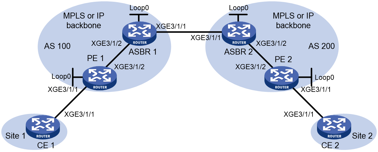
Table 7 Interface and IP address assignment
|
Device |
Interface |
IP address |
Device |
Interface |
IP address |
|
CE 1 |
XGE3/1/1 |
100.1.1.1/24 |
ASBR 1 |
Loop0 |
192.2.2.2/32 |
|
PE 1 |
Loop0 |
192.1.1.1/32 |
|
XGE3/1/2 |
23.1.1.2/24 |
|
|
XGE3/1/2 |
23.1.1.1/24 |
|
XGE3/1/1 |
26.2.2.2/24 |
|
PE 2 |
Loop0 |
192.4.4.4/32 |
ASBR 2 |
Loop0 |
192.3.3.3/32 |
|
|
XGE3/1/2 |
22.2.2.1/24 |
|
XGE3/1/1 |
26.2.2.3/24 |
|
CE 2 |
XGE3/1/1 |
100.1.1.2/24 |
|
XGE3/1/2 |
22.2.2.3/24 |
Procedure
1. Configure CE 1.
<CE1> system-view
[CE1] interface ten-gigabitethernet 3/1/1
[CE1-Ten-GigabitEthernet3/1/1] ip address 100.1.1.1 24
[CE1-Ten-GigabitEthernet3/1/1] quit
2. Configure PE 1:
# Configure an LSR ID.
<PE1> system-view
[PE1] interface loopback 0
[PE1-LoopBack0] ip address 192.1.1.1 32
[PE1-LoopBack0] quit
[PE1] mpls lsr-id 192.1.1.1
# Enable L2VPN.
[PE1] l2vpn enable
# Enable global LDP.
[PE1] mpls ldp
[PE1-ldp] quit
# Configure Ten-GigabitEthernet 3/1/2 (the interface connected to ASBR 1), and enable LDP on the interface.
[PE1] interface ten-gigabitethernet 3/1/2
[PE1-Ten-GigabitEthernet3/1/2] ip address 23.1.1.1 24
[PE1-Ten-GigabitEthernet3/1/2] mpls enable
[PE1-Ten-GigabitEthernet3/1/2] mpls ldp enable
[PE1-Ten-GigabitEthernet3/1/2] quit
# Configure OSPF for LDP to create LSPs.
[PE1] ospf
[PE1-ospf-1] area 0
[PE1-ospf-1-area-0.0.0.0] network 23.1.1.1 0.0.0.255
[PE1-ospf-1-area-0.0.0.0] network 192.1.1.1 0.0.0.0
[PE1-ospf-1-area-0.0.0.0] quit
[PE1-ospf-1] quit
# Create a cross-connect group named vpn1, create a cross-connect named ldp in the group, and bind Ten-GigabitEthernet 3/1/1 to the cross-connect.
[PE1] xconnect-group vpn1
[PE1-xcg-vpn1] connection ldp
[PE1-xcg-vpn1-ldp] ac interface ten-gigabitethernet 3/1/1
[PE1-xcg-vpn1-ldp-Ten-GigabitEthernet3/1/1] quit
# Create an LDP PW for the cross-connect to bind the AC to the PW.
[PE1-xcg-vpn1-ldp] peer 192.2.2.2 pw-id 1000
[PE1-xcg-vpn1-ldp-192.2.2.2-1000] quit
[PE1-xcg-vpn1-ldp] quit
[PE1-xcg-vpn1] quit
3. Configure ASBR 1:
# Configure an LSR ID.
<ASBR1> system-view
[ASBR1] interface loopback 0
[ASBR1-LoopBack0] ip address 192.2.2.2 32
[ASBR1-LoopBack0] quit
[ASBR1] mpls lsr-id 192.2.2.2
# Enable L2VPN.
[ASBR1] l2vpn enable
# Enable global LDP.
[ASBR1] mpls ldp
[ASBR1-ldp] quit
# Configure Ten-GigabitEthernet 3/1/2 (the interface connected to PE 1), and enable LDP on the interface.
[ASBR1] interface ten-gigabitethernet 3/1/2
[ASBR1-Ten-GigabitEthernet3/1/2] ip address 23.1.1.2 24
[ASBR1-Ten-GigabitEthernet3/1/2] mpls enable
[ASBR1-Ten-GigabitEthernet3/1/2] mpls ldp enable
[ASBR1-Ten-GigabitEthernet3/1/2] quit
# Configure Ten-GigabitEthernet 3/1/1 (the interface connected to ASBR 2), and enable MPLS on the interface.
[ASBR1] interface ten-gigabitethernet 3/1/1
[ASBR1-Ten-GigabitEthernet3/1/1] ip address 26.2.2.2 24
[ASBR1-Ten-GigabitEthernet3/1/1] mpls enable
[ASBR1-Ten-GigabitEthernet3/1/1] quit
# Configure OSPF for LDP to create LSPs.
[ASBR1] ospf
[ASBR1-ospf-1] area 0
[ASBR1-ospf-1-area-0.0.0.0] network 23.1.1.2 0.0.0.255
[ASBR1-ospf-1-area-0.0.0.0] network 192.2.2.2 0.0.0.0
[ASBR1-ospf-1-area-0.0.0.0] quit
[ASBR1-ospf-1] quit
# Configure BGP to advertise labeled routes on ASBR 1.
[ASBR1] bgp 100
[ASBR1-bgp-default] peer 26.2.2.3 as-number 200
[ASBR1-bgp-default] address-family ipv4 unicast
[ASBR1-bgp-default-ipv4] import-route direct
[ASBR1-bgp-default-ipv4] peer 26.2.2.3 enable
[ASBR1-bgp-default-ipv4] peer 26.2.2.3 route-policy policy1 export
[ASBR1-bgp-default-ipv4] peer 26.2.2.3 label-route-capability
[ASBR1-bgp-default-ipv4] quit
[ASBR1-bgp-default] quit
[ASBR1] route-policy policy1 permit node 1
[ASBR1-route-policy-policy1-1] apply mpls-label
[ASBR1-route-policy-policy1-1] quit
# Create a cross-connect group named vpn1, create a cross-connect named ldp in the group, and create two LDP PWs for the cross-connect to form a multi-segment PW.
[ASBR1] xconnect-group vpn1
[ASBR1-xcg-vpn1] connection ldp
[ASBR1-xcg-vpn1-ldp] peer 192.1.1.1 pw-id 1000
[ASBR1-xcg-vpn1-ldp-192.1.1.1-1000] quit
[ASBR1-xcg-vpn1-ldp] peer 192.3.3.3 pw-id 1000
[ASBR1-xcg-vpn1-ldp-192.3.3.3-1000] quit
[ASBR1-xcg-vpn1-ldp] quit
[ASBR1-xcg-vpn1] quit
4. Configure ASBR 2:
# Configure an LSR ID.
<ASBR2> system-view
[ASBR2] interface loopback 0
[ASBR2-LoopBack0] ip address 192.3.3.3 32
[ASBR2-LoopBack0] quit
[ASBR2] mpls lsr-id 192.3.3.3
# Enable L2VPN.
[ASBR2] l2vpn enable
# Enable global LDP.
[ASBR2] mpls ldp
[ASBR2-ldp] quit
# Configure Ten-GigabitEthernet 3/1/2 (the interface connected to PE 2), and enable LDP on the interface.
[ASBR2] interface ten-gigabitethernet 3/1/2
[ASBR2-Ten-GigabitEthernet3/1/2] ip address 22.2.2.3 24
[ASBR2-Ten-GigabitEthernet3/1/2] mpls enable
[ASBR2-Ten-GigabitEthernet3/1/2] mpls ldp enable
[ASBR2-Ten-GigabitEthernet3/1/2] quit
# Configure Ten-GigabitEthernet 3/1/1 (the interface connected to ASBR 1), and enable MPLS on the interface.
[ASBR2] interface ten-gigabitethernet 3/1/1
[ASBR2-Ten-GigabitEthernet3/1/1] ip address 26.2.2.3 24
[ASBR2-Ten-GigabitEthernet3/1/1] mpls enable
[ASBR2-Ten-GigabitEthernet3/1/1] quit
# Configure OSPF for LDP to create LSPs.
[ASBR2] ospf
[ASBR2-ospf-1] area 0
[ASBR2-ospf-1-area-0.0.0.0] network 22.2.2.3 0.0.0.255
[ASBR2-ospf-1-area-0.0.0.0] network 192.3.3.3 0.0.0.0
[ASBR2-ospf-1-area-0.0.0.0] quit
[ASBR2-ospf-1] quit
# Configure BGP to advertise labeled routes on ASBR 2.
[ASBR2] bgp 200
[ASBR2-bgp-default] peer 26.2.2.2 as-number 100
[ASBR2-bgp-default] address-family ipv4 unicast
[ASBR2-bgp-default-ipv4] import-route direct
[ASBR2-bgp-default-ipv4] peer 26.2.2.2 enable
[ASBR2-bgp-default-ipv4] peer 26.2.2.2 route-policy policy1 export
[ASBR2-bgp-default-ipv4] peer 26.2.2.2 label-route-capability
[ASBR2-bgp-default-ipv4] quit
[ASBR2-bgp-default] quit
[ASBR2] route-policy policy1 permit node 1
[ASBR2-route-policy-policy1-1] apply mpls-label
[ASBR2-route-policy-policy1-1] quit
# Create a cross-connect group named vpn1, create a cross-connect named ldp in the group, and create two LDP PWs for the cross-connect to form a multi-segment PW.
[ASBR2] xconnect-group vpn1
[ASBR2-xcg-vpn1] connection ldp
[ASBR2-xcg-vpn1-ldp] peer 192.2.2.2 pw-id 1000
[ASBR2-xcg-vpn1-ldp-192.2.2.2-1000] quit
[ASBR2-xcg-vpn1-ldp] peer 192.4.4.4 pw-id 1000
[ASBR2-xcg-vpn1-ldp-192.4.4.4-1000] quit
[ASBR2-xcg-vpn1-ldp] quit
[ASBR2-xcg-vpn1] quit
5. Configure PE 2:
# Configure an LSR ID.
<PE2> system-view
[PE2] interface loopback 0
[PE2-LoopBack0] ip address 192.4.4.4 32
[PE2-LoopBack0] quit
[PE2] mpls lsr-id 192.4.4.4
# Enable L2VPN.
[PE2] l2vpn enable
# Enable global LDP.
[PE2] mpls ldp
[PE2-ldp] quit
# Configure Ten-GigabitEthernet 3/1/2 (the interface connected to ASBR 2), and enable LDP on the interface.
[PE2] interface ten-gigabitethernet 3/1/2
[PE2-Ten-GigabitEthernet3/1/2] ip address 22.2.2.1 24
[PE2-Ten-GigabitEthernet3/1/2] mpls enable
[PE2-Ten-GigabitEthernet3/1/2] mpls ldp enable
[PE2-Ten-GigabitEthernet3/1/2] quit
# Configure OSPF for LDP to create LSPs.
[PE2] ospf
[PE2-ospf-1] area 0
[PE2-ospf-1-area-0.0.0.0] network 192.4.4.4 0.0.0.0
[PE2-ospf-1-area-0.0.0.0] network 22.2.2.1 0.0.0.255
[PE2-ospf-1-area-0.0.0.0] quit
[PE2-ospf-1] quit
# Create a cross-connect group named vpn1, create a cross-connect named ldp in the group, and bind Ten-GigabitEthernet 3/1/1 to the cross-connect.
[PE2] xconnect-group vpn1
[PE2-xcg-vpn1] connection ldp
[PE2-xcg-vpn1-ldp] ac interface ten-gigabitethernet 3/1/1
[PE2-xcg-vpn1-ldp-Ten-GigabitEthernet3/1/1] quit
# Create an LDP PW for the cross-connect to bind the AC to the PW.
[PE2-xcg-vpn1-ldp] peer 192.3.3.3 pw-id 1000
[PE2-xcg-vpn1-ldp-192.3.3.3-1000] quit
[PE2-xcg-vpn1-ldp] quit
[PE2-xcg-vpn1] quit
6. Configure CE 2.
<CE2> system-view
[CE2] interface ten-gigabitethernet 3/1/1
[CE2-Ten-GigabitEthernet3/1/1] ip address 100.1.1.2 24
[CE2-Ten-GigabitEthernet3/1/1] quit
Verifying the configuration
# Verify that an LDP PW has been created on PE 1.
[PE1] display l2vpn pw
Flags: M - main, B - backup, E - ecmp, BY - bypass, H - hub link, S - spoke link
N - no split horizon, A - administration, ABY – ac-bypass
PBY – pw-bypass
Total number of PWs: 1
1 up, 0 blocked, 0 down, 0 defect, 0 idle, 0 duplicate
Xconnect-group Name: vpn1
Peer PWID/RmtSite/SrvID In/Out Label Proto Flag Link ID State
192.2.2.2 1000 1151/1279 LDP M Up
# Verify that two LDP PWs have been created to form a multi-segment PW on ASBR 1.
[ASBR1] display l2vpn pw
Flags: M - main, B - backup, E - ecmp, BY - bypass, H - hub link, S - spoke link
N - no split horizon, A - administration, ABY – ac-bypass
PBY – pw-bypass
Total number of PWs: 2
2 up, 0 blocked, 0 down, 0 defect, 0 idle, 0 duplicate
Xconnect-group Name: vpn1
Peer PWID/RmtSite/SrvID In/Out Label Proto Flag Link ID State
192.1.1.1 1000 1279/1151 LDP M 0 Up
192.3.3.3 1000 1278/1151 LDP M 1 Up
# Verify that two LDP PWs have been created to form a multi-segment PW on ASBR 2.
[ASBR2] display l2vpn pw
Flags: M - main, B - backup, E - ecmp, BY - bypass, H - hub link, S - spoke link
N - no split horizon, A - administration, ABY – ac-bypass
PBY – pw-bypass
Total number of PWs: 2
2 up, 0 blocked, 0 down, 0 defect, 0 idle, 0 duplicate
Xconnect-group Name: vpn1
Peer PWID/RmtSite/SrvID In/Out Label Proto Flag Link ID State
192.2.2.2 1000 1151/1278 LDP M 0 Up
192.4.4.4 1000 1150/1279 LDP M 1 Up
# Verify that an LDP PW has been created on PE 2.
[PE2] display l2vpn pw
Flags: M - main, B - backup, E - ecmp, BY - bypass, H - hub link, S - spoke link
N - no split horizon, A - administration, ABY – ac-bypass
PBY – pw-bypass
Total number of PWs: 1
1 up, 0 blocked, 0 down, 0 defect, 0 idle, 0 duplicate
Xconnect-group Name: vpn1
Peer PWID/RmtSite/SrvID In/Out Label Proto Flag Link ID State
192.3.3.3 1000 1279/1150 LDP M 1 Up
# Verify that CE 1 and CE 2 can ping each other. (Details not shown.)
