- Table of Contents
-
- 04-Layer 2—LAN Switching Configuration Guide
- 00-Preface
- 01-MAC address table configuration
- 02-Ethernet link aggregation configuration
- 03-Port isolation configuration
- 04-VLAN configuration
- 05-MVRP configuration
- 06-QinQ configuration
- 07-VLAN mapping configuration
- 08-VLAN termination configuration
- 09-Loop detection configuration
- 10-Spanning tree configuration
- 11-LLDP configuration
- Related Documents
-
| Title | Size | Download |
|---|---|---|
| 09-Loop detection configuration | 144.87 KB |
Contents
Configuring loop detection in an L2VPN network
About loop detection in an L2VPN network
Loop detection application scenarios in L2VPN networks
L2VPN loop detection tasks at a glance
Enabling loop detection in an L2VPN network
Setting the loop protection action
Setting the loop detection interval
Setting the priority value in the loop detection priority
Display and maintenance commands for L2VPN loop detection
Configuring loop detection in an L2VPN network
About loop detection in an L2VPN network
Loop detection periodically checks for Layer 2 loops in an L2VPN network. The mechanism immediately generates a log when a loop occurs so that you are promptly notified to adjust network connections and configurations. You can configure loop detection to block the looped interface. Logs are maintained in the information center. For more information, see Network Management and Monitoring Configuration Guide.
Loop detection frame format
As shown in Figure 1, a loop detection frame contains the Ethernet header, loop detection header, and loop detection TLVs.
Figure 1 Loop detection frame format
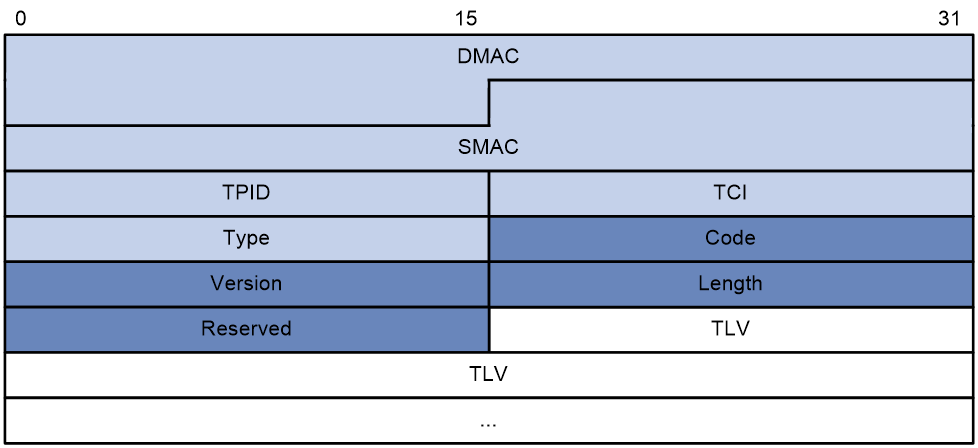
The Ethernet frame header of a loop detection frame contains the following fields:
· DMAC—Destination MAC address of the frame, which is the multicast MAC address 010f-e200-0007. When a loop detection-enabled device receives a frame with this destination MAC address, it performs the following operations:
¡ Sends the frame to the CPU.
¡ Floods the frame in the VLAN from which the frame was originally received.
· SMAC—Source MAC address of the frame, which is the bridge MAC address of the sending device.
· TPID—Type of the VLAN tag, with the default value of 0x8100.
· TCI—Tag control information, including the priority and VLAN ID.
· Type—Protocol type, with the value of 0x8918.
The loop detection header of a loop detection frame contains the following fields:
· Code—Protocol sub-type, which is 0x0001, indicating the loop detection type.
· Version—Protocol version, which is reserved. This field is fixed at 0x0000.
· Length—Length of the frame. The value includes the loop detection header, but excludes the Ethernet header.
· Reserved—This field is reserved.
Payload of a loop detection frame is encapsulated as TLV triplets.
Table 1 TLVs supported by loop detection
|
TLV |
Description |
Remarks |
|
End of PDU |
End of a PDU. |
Optional. |
|
Device ID |
Bridge MAC address of the sending device. |
Required. |
|
Port ID |
ID of the PDU sending port. |
Required. |
|
Port Name |
Name of the PDU sending port. |
Optional. |
|
System Name |
Device name. |
Optional. |
|
Chassis ID |
Chassis ID of the sending port. |
Optional. |
|
Slot ID |
Slot ID of the sending port. |
Optional. |
|
Sub Slot ID |
Sub-slot ID of the sending port. |
Optional. |
|
Priority of Port |
Priority of the sending port. |
Required. |
Loop detection application scenarios in L2VPN networks
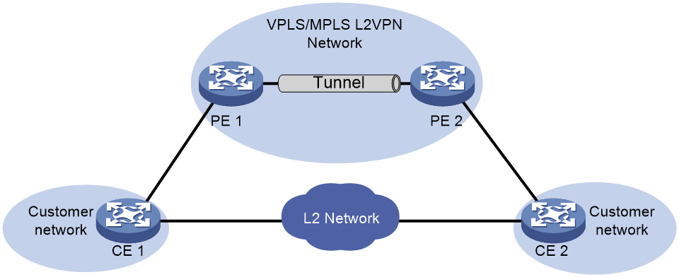
Remote site loop detection
As shown in Figure 2, two PEs provide data transmission services for the CEs attached to the customer network sites. Because the CEs have Layer 2 connectivity, broadcast storms can spread across the customer network sites.
To remove loops from the VPLS or MPLS L2VPN network, configure loop detection on the PE interfaces that are attached to CEs. When a PE detects a loop on a CE-facing interface, it blocks the interface to remove the loop.
Figure 2 Remote site loop detection
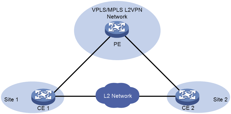
Local site loop detection
As shown in Figure 3, a PE is attached to two CEs at the local sites, and the CEs have Layer 2 connectivity. To remove loops from the local sites, configure loop detection on the PE interfaces that are attached to CEs. When a PE detects a loop on a CE-facing interface, it blocks the interface to remove the loop.
Figure 3 Intra-site loop detection
Loop detection mechanisms
Loop identification
After you enable loop detection on an interface, it keeps sending loop detection frames and detecting incoming loop detection frames at the same time. If the interface receives a loop detection frame with high priority from any device, it determines that a loop exists.
Loop detection is a continuous process as the network changes. Loop detection frames are sent at the loop detection interval to determine whether loops occur on interfaces and whether loops are removed.
Loop detection priority
The loop detection frames sent by an interface carry the loop detection priority of the interface. The loop detection priority contains the priority value, the bridge MAC address, and the port ID. When an interface receives a loop detection frame, it compares its own loop detection priority with that in the frame to identify whether a loop exists. If the loop detection priority in the frame is higher, a loop exists in the L2VPN network. If the loop detection priority of the interface is higher, the interface drops the frame.
An interface uses the following procedure to compare its loop detection priority with that in an incoming loop detection frame:
1. Compares the priority values. The smaller the value, the higher the priority.
2. Compares the bridge MAC addresses if the priority values are the same. A lower bridge MAC address has a higher priority.
3. Compares the port IDs if the bridge MAC addresses are the same, which indicates the loop detection frame is sent by another interface of the device. A smaller port ID has a higher priority.
Port status auto recovery
When the device configured with the block action detects a loop on an interface, it generates a log, disables MAC address learning on the interface, and blocks the interface. If the device does not receive a loop detection frame within three loop detection intervals, it performs the following operations:
· Automatically sets the interface to the forwarding state.
· Notifies the user of the event.
L2VPN loop detection tasks at a glance
To configure loop detection in an L2VPN network, perform the following tasks:
1. Enabling loop detection in an L2VPN network
2. (Optional) Setting the loop protection action
3. (Optional) Setting the loop detection interval
4. (Optional) Setting the priority value in the loop detection priority
Enabling loop detection in an L2VPN network
Restrictions and guidelines
When you configure loop detection in an L2VPN network, follow these restrictions and guidelines:
· The device sends loop detection frames out of all loop detection-enabled interfaces, which consumes system resources. When you select the interfaces to enable loop detection, consider both the system resource consumption and your network environment to achieve the optimal result.
· You can enable single-tagged loop detection or double-tagged loop detection on an interface. You cannot enable both types of loop detection on an interface.
· On an interface, the number of VLAN tag layers of loop detection frames must match the VLAN termination configuration, and the VLAN IDs in the frames must be terminated by the interface. For more information about VLAN termination, see "Configuring VLAN termination."
· For loop detection to work correctly in a VPLS or MPLS L2VPN network, you must enable loop detection and configure the same loop detection interval on all PEs.
Procedure
1. Enter system view.
system-view
2. Enter Layer 3 Ethernet subinterface view or Layer 3 aggregate subinterface view.
interface interface-type interface-number.subnumber
3. Enable loop detection. Choose one of the following options:
¡ Enable single-tagged loop detection.
loopback-detection enable vlan { vlan-id-list | all }
¡ Enable double-tagged loop detection.
loopback-detection enable s-vid vlan-id c-vid { vlan-id-list | all }
By default, loop detection is disabled on interfaces.
Setting the loop protection action
About this task
You can set the loop protection action to block. If a loop is detected, the device performs the following operations:
· Generates a log.
· Disables MAC address learning.
· Blocks the interface.
Procedure
1. Enter system view.
system-view
2. Enter Layer 3 Ethernet subinterface view or Layer 3 aggregate subinterface view.
interface interface-type interface-number.subnumber
3. Set the loop protection action.
loopback-detection action block
By default, the device generates a log but performs no action on the interface on which a loop is detected.
Setting the loop detection interval
About this task
With loop detection enabled, the device sends loop detection frames at the loopback detection interval. A shorter interval offers more sensitive detection but consumes more resources. Consider the system performance and loop detection speed when you set the loop detection interval.
Procedure
1. Enter system view.
system-view
2. Set the loop detection interval.
loopback-detection interval-time interval
The default loop detection interval is 30 seconds.
Setting the priority value in the loop detection priority
About this task
Perform this task to configure the device to block interfaces based on their priorities when loops are detected.
Procedure
1. Enter system view.
system-view
2. Enter Layer 3 Ethernet subinterface view or Layer 3 aggregate subinterface view.
interface interface-type interface-number.subnumber
3. Set the priority value in the loop detection priority.
loopback-detection priority priority
By default, the priority value is 7 in the loop detection priority of an interface.
Display and maintenance commands for L2VPN loop detection
Execute display commands in any view.
|
Task |
Command |
|
Display the loop detection configuration and status. |
display loopback-detection |
L2VPN loop detection configuration examples
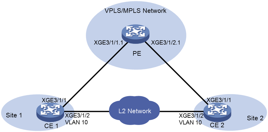
Example: Configuring local site loop detection
Network configuration
As shown in Figure 4, the PE provides user traffic transmission service for the CEs of the local sites, and the CEs have Layer 2 connectivity in VLAN 10. Configure loop detection on the CE-facing interfaces of the PE so that the PE can block the interfaces if loops exist.
Procedure
1. Configure CE 1:
# Configure Ten-GigabitEthernet 3/1/1 and Ten-GigabitEthernet 3/1/2 as trunk ports, and assign them to VLAN 10.
<CE1> system-view
[CE1] interface ten-gigabitethernet 3/1/1
[CE1-Ten-GigabitEthernet3/1/1] port link-type trunk
[CE1-Ten-GigabitEthernet3/1/1] port trunk permit vlan 10
[CE1-Ten-GigabitEthernet3/1/1] quit
[CE1] interface ten-gigabitethernet 3/1/2
[CE1-Ten-GigabitEthernet3/1/2] port link-type trunk
[CE1-Ten-GigabitEthernet3/1/2] port trunk permit vlan 10
[CE1-Ten-GigabitEthernet3/1/2] quit
2. Configure CE 2:
# Configure Ten-GigabitEthernet 3/1/1 and Ten-GigabitEthernet 3/1/2 as trunk ports, and assign them to VLAN 10.
<CE2> system-view
[CE2] interface ten-gigabitethernet 3/1/1
[CE2-Ten-GigabitEthernet3/1/1] port link-type trunk
[CE2-Ten-GigabitEthernet3/1/1] port trunk permit vlan 10
[CE2-Ten-GigabitEthernet3/1/1] quit
[CE2] interface ten-gigabitethernet 3/1/2
[CE2-Ten-GigabitEthernet3/1/2] port link-type trunk
[CE2-Ten-GigabitEthernet3/1/2] port trunk permit vlan 10
[CE2-Ten-GigabitEthernet3/1/2] quit
3. Configure the PE:
# Enable L2VPN.
<PE> system-view
[PE] l2vpn enable
# Create a cross-connect group named vpn1, create a cross-connect named vpn1 in the group, and bind Ten-GigabitEthernet 3/1/1 and Ten-GigabitEthernet 3/1/2 to the cross-connect.
[PE] xconnect-group vpn1
[PE-xcg-vpn1] connection vpn1
[PE-xcg-vpn1-vpn1] ac interface ten-gigabitethernet 3/1/1
[PE-xcg-vpn1-vpn1] ac interface ten-gigabitethernet 3/1/2
[PE-xcg-vpn1-vpn1] quit
# Configure Ten-GigabitEthernet 3/1/1.1 to terminate VLAN 10, and enable single-tagged loop detection on it.
[PE] interface ten-gigabitethernet 3/1/1.1
[PE-Ten-GigabitEthernet3/1/1.1] vlan-type dot1q vid 10
[PE-Ten-GigabitEthernet3/1/1.1] loopback-detection enable vlan 10
# Set the priority value in the loop detection priority to 2, and set the loop protection action to block.
[PE-Ten-GigabitEthernet3/1/1.1] loopback-detection priority 2
[PE-Ten-GigabitEthernet3/1/1.1] loopback-detection action block
[PE-Ten-GigabitEthernet3/1/1.1] quit
# Configure Ten-GigabitEthernet 3/1/2.1 to terminate VLAN 10, and enable single-tagged loop detection on it.
[PE] interface ten-gigabitethernet 3/1/2.1
[PE-Ten-GigabitEthernet3/1/2.1] vlan-type dot1q vid 10
[PE-Ten-GigabitEthernet3/1/2.1] loopback-detection enable vlan 10
# Set the priority value in the loop detection priority to 3, and set the loop protection action to block.
[PE-Ten-GigabitEthernet3/1/2.1] loopback-detection priority 3
[PE-Ten-GigabitEthernet3/1/2.1] loopback-detection action block
[PE-Ten-GigabitEthernet3/1/2.1] quit
# Set the loop detection interval to 40 seconds.
[PE] loopback-detection interval-time 40
Verifying the configuration
# Verify that the PE has detected a loop.
[PE]
%Oct 27 22:52:11:722 2020 H3C LPDT/4/LPDT_LOOPED A loop was detected on
Ten-GigabitEthernet3/1/2.1.
%Oct 27 22:52:11:723 2020 H3C LPDT/4/LPDT_VLAN_LOOPED A loop was detect
ed on Ten-GigabitEthernet3/1/2.1 in VLAN 10.
# Verify that the PE has blocked Ten-GigabitEthernet 3/1/2.1 to remove the loop.
[PE] display loopback-detection
Loop detection is enabled.
Loop detection interval is 40 second(s).
Loop is detected on following interfaces:
Interface Action mode
Ten-GigabitEthernet3/1/2.1 Block
