- Table of Contents
-
- 04-Layer 2—LAN Switching Configuration Guide
- 00-Preface
- 01-MAC address table configuration
- 02-Ethernet link aggregation configuration
- 03-Port isolation configuration
- 04-VLAN configuration
- 05-MVRP configuration
- 06-QinQ configuration
- 07-VLAN mapping configuration
- 08-VLAN termination configuration
- 09-Loop detection configuration
- 10-Spanning tree configuration
- 11-LLDP configuration
- Related Documents
-
| Title | Size | Download |
|---|---|---|
| 04-VLAN configuration | 211.66 KB |
Contents
Layer 3 communication between VLANs
Restrictions and guidelines: VLAN configuration
Restrictions and guidelines for port-based VLANs
Assigning an access port to a VLAN
Assigning a trunk port to a VLAN
Assigning a hybrid port to a VLAN
VLAN interfaces configuration tasks at a glance
Enabling packet statistics collection on a VLAN interface
Enabling interframe gap and preamble statistics in the traffic statistics
Restoring the default settings for the VLAN interface
Display and maintenance commands for VLANs
Example: Configuring port-based VLANs
Restrictions and guidelines: Super VLAN configuration
Configuring a super VLAN interface
Display and maintenance commands for super VLANs
Super VLAN configuration examples
Example: Configuring a super VLAN
Configuring VLANs
About VLANs
The Virtual Local Area Network (VLAN) technology divides a physical LAN into multiple logical LANs. It has the following benefits:
· Security—Hosts in the same VLAN can communicate with one another at Layer 2, but they are isolated from hosts in other VLANs at Layer 2.
· Broadcast traffic isolation—Each VLAN is a broadcast domain that limits the transmission of broadcast packets.
· Flexibility—A VLAN can be logically divided on a workgroup basis. Hosts in the same workgroup can be assigned to the same VLAN, regardless of their physical locations.
VLAN frame encapsulation
To identify Ethernet frames from different VLANs, IEEE 802.1Q inserts a four-byte VLAN tag between the destination and source MAC address (DA&SA) field and the Type field.
Figure 1 VLAN tag placement and format
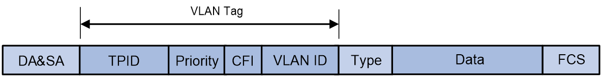
A VLAN tag includes the following fields:
· TPID—16-bit tag protocol identifier that indicates whether a frame is VLAN-tagged. By default, the hexadecimal TPID value 8100 identifies a VLAN-tagged frame. A device vendor can set the TPID to a different value. For compatibility with a neighbor device, set the TPID value on the device to be the same as the neighbor device.
· Priority—3-bit long, identifies the 802.1p priority of the frame. For more information, see ACL and QoS Configuration Guide.
· CFI—1-bit long canonical format indicator that indicates whether the MAC addresses are encapsulated in the standard format when packets are transmitted across different media. Available values include:
¡ 0 (default)—The MAC addresses are encapsulated in the standard format.
¡ 1—The MAC addresses are encapsulated in a non-standard format.
This field is always set to 0 for Ethernet.
· VLAN ID—12-bit long, identifies the VLAN to which the frame belongs. The VLAN ID range is 0 to 4095. VLAN IDs 0 and 4095 are reserved, and VLAN IDs 1 to 4094 are user configurable.
The way a network device handles an incoming frame depends on whether the frame has a VLAN tag and the value of the VLAN tag (if any).
Ethernet supports encapsulation formats Ethernet II, 802.3/802.2 LLC, 802.3/802.2 SNAP, and 802.3 raw. The Ethernet II encapsulation format is used here. For information about the VLAN tag fields in other frame encapsulation formats, see related protocols and standards.
For a frame that has multiple VLAN tags, the device handles it according to its outermost VLAN tag and transmits its inner VLAN tags as the payload.
Port-based VLANs
Port-based VLANs group VLAN members by port. A port forwards packets from a VLAN only after it is assigned to the VLAN.
Port link type
You can set the link type of a port to access, trunk, or hybrid. The port link type determines whether the port can be assigned to multiple VLANs. The link types use the following VLAN tag handling methods:
· Access—An access port can forward packets only from one VLAN and send these packets untagged. An access port is typically used in the following conditions:
¡ Connecting to a terminal device that does not support VLAN packets.
¡ In scenarios that do not distinguish VLANs.
· Trunk—A trunk port can forward packets from multiple VLANs. Except packets from the port VLAN ID (PVID), packets sent out of a trunk port are VLAN-tagged. Ports connecting network devices are typically configured as trunk ports.
· Hybrid—A hybrid port can forward packets from multiple VLANs. The tagging status of the packets forwarded by a hybrid port depends on the port configuration.
PVID
The PVID identifies the default VLAN of a port. Untagged packets received on a port are considered as the packets from the port PVID.
An access port can join only one VLAN. The VLAN to which the access port belongs is the PVID of the port. A trunk or hybrid port supports multiple VLANs and the PVID configuration.
How ports of different link types handle frames
|
Actions |
Access |
Trunk |
Hybrid |
|
|
In the inbound direction for an untagged frame |
Tags the frame with the PVID tag. |
· If the PVID is permitted on the port, tags the frame with the PVID tag. · If not, drops the frame. |
||
|
In the inbound direction for a tagged frame |
· Receives the frame if its VLAN ID is the same as the PVID. · Drops the frame if its VLAN ID is different from the PVID. |
· Receives the frame if its VLAN is permitted on the port. · Drops the frame if its VLAN is not permitted on the port. |
||
|
In the outbound direction |
Removes the VLAN tag and sends the frame. |
· Removes the tag and sends the frame if the frame carries the PVID tag and the port belongs to the PVID. · Sends the frame without removing the tag if its VLAN is carried on the port but is different from the PVID. |
Sends the frame if its VLAN is permitted on the port. The tagging status of the frame depends on the port hybrid vlan command configuration. |
|
Layer 3 communication between VLANs
Hosts of different VLANs use VLAN interfaces to communicate at Layer 3. VLAN interfaces are virtual interfaces that do not exist as physical entities on devices. For each VLAN, you can create one VLAN interface and assign an IP address to it. The VLAN interface acts as the gateway of the VLAN to forward packets at Layer 3. When the IP addresses of multiple VLAN interfaces are on different subnets, you must configure IP routing protocols to enable Layer 3 communication between these IP addresses. Then, the devices can forward packets at Layer 3 across subnets between different VLANs. For more information about IP routing protocols, see Layer 3—IP Routing Configuration Guide.
Protocols and standards
IEEE 802.1Q, IEEE Standard for Local and Metropolitan Area Networks: Virtual Bridged Local Area Networks
Restrictions and guidelines: VLAN configuration
· As the system default VLAN, VLAN 1 cannot be created or deleted.
· Before you delete a dynamic VLAN or a VLAN locked by an application, you must first remove the configuration from the VLAN.
Creating VLANs
1. Enter system view.
system-view
2. Create one or multiple VLANs.
¡ Create a VLAN and enter its view.
vlan vlan-id
¡ Create multiple VLANs and enter VLAN view.
Create VLANs.
vlan { vlan-id1 to vlan-id2 | all }
Enter VLAN view.
vlan vlan-id
By default, only the system default VLAN (VLAN 1) exists.
3. (Optional.) Set a name for the VLAN.
name text
By default, the name of a VLAN is VLAN vlan-id. The vlan-id argument specifies the VLAN ID in a four-digit format. If the VLAN ID has fewer than four digits, leading zeros are added. For example, the name of VLAN 100 is VLAN 0100.
4. (Optional.) Configure the description for the VLAN.
description text
By default, the description of a VLAN is VLAN vlan-id. The vlan-id argument specifies the VLAN ID in a four-digit format. If the VLAN ID has fewer than four digits, leading zeros are added. For example, the default description of VLAN 100 is VLAN 0100.
Configuring port-based VLANs
Restrictions and guidelines for port-based VLANs
· When you use the undo vlan command to delete the PVID of a port, either of the following events occurs depending on the port link type:
¡ For an access port, the PVID of the port changes to VLAN 1.
¡ For a hybrid or trunk port, the PVID setting of the port does not change.
You can use a nonexistent VLAN as the PVID for a hybrid or trunk port, but not for an access port.
· As a best practice, set the same PVID for a local port and its peer.
· To prevent a port from dropping untagged packets or PVID-tagged packets, assign the port to its PVID.
Assigning an access port to a VLAN
About this task
You can assign an access port to a VLAN in VLAN view or interface view.
Assigning one or multiple access ports to a VLAN in VLAN view
1. Enter system view.
system-view
2. Enter VLAN view.
vlan vlan-id
3. Assign one or multiple access ports to the VLAN.
port interface-list
By default, all ports belong to VLAN 1.
Assigning an access port to a VLAN in interface view
1. Enter system view.
system-view
2. Enter interface view.
¡ Enter Layer 2 Ethernet interface view.
interface interface-type interface-number
¡ Enter Layer 2 aggregate interface view.
interface bridge-aggregation interface-number
¡ Enter virtual Layer 2 Ethernet interface view.
interface virtual-bridge-port interface-number
¡ Enter virtual Layer 2 aggregate interface view.
interface vagg-bridge-port interface-number
¡ Enter Layer 2 FlexE logical interface view.
interface flexe interface-number
3. Set the port link type to access.
port link-type access
By default, all ports are access ports.
4. Assign the access port to a VLAN.
port access vlan vlan-id
By default, all access ports belong to VLAN 1.
Assigning a trunk port to a VLAN
About this task
A trunk port supports multiple VLANs. You can assign it to a VLAN in interface view.
Restrictions and guidelines
To change the link type of a port from trunk to hybrid, set the link type to access first.
To enable a trunk port to transmit packets from its PVID, you must assign the trunk port to the PVID by using the port trunk permit vlan command.
Procedure
1. Enter system view.
system-view
2. Enter interface view.
¡ Enter Layer 2 Ethernet interface view.
interface interface-type interface-number
¡ Enter Layer 2 aggregate interface view.
interface bridge-aggregation interface-number
¡ Enter virtual Layer 2 Ethernet interface view.
interface virtual-bridge-port interface-number
¡ Enter virtual Layer 2 aggregate interface view.
interface vagg-bridge-port interface-number
¡ Enter Layer 2 FlexE logical interface view.
interface flexe interface-number
3. Set the port link type to trunk.
port link-type trunk
By default, all ports are access ports.
4. Assign the trunk port to the specified VLANs.
port trunk permit vlan { vlan-id-list | all }
By default, a trunk port permits only VLAN 1.
5. (Optional.) Set the PVID for the trunk port.
port trunk pvid vlan vlan-id
The default setting is VLAN 1.
Assigning a hybrid port to a VLAN
About this task
A hybrid port supports multiple VLANs. You can assign it to the specified VLANs in interface view. Make sure the VLANs have been created.
Restrictions and guidelines
To change the link type of a port from trunk to hybrid, set the link type to access first.
To enable a hybrid port to transmit packets from its PVID, you must assign the hybrid port to the PVID by using the port hybrid vlan command.
Procedure
1. Enter system view.
system-view
2. Enter interface view.
¡ Enter Layer 2 Ethernet interface view.
interface interface-type interface-number
¡ Enter Layer 2 aggregate interface view.
interface bridge-aggregation interface-number
¡ Enter virtual Layer 2 Ethernet interface view.
interface virtual-bridge-port interface-number
¡ Enter virtual Layer 2 aggregate interface view.
interface vagg-bridge-port interface-number
¡ Enter Layer 2 FlexE logical interface view.
interface flexe interface-number
3. Set the port link type to hybrid.
port link-type hybrid
By default, all ports are access ports.
4. Assign the hybrid port to the specified VLANs.
port hybrid vlan vlan-id-list { tagged | untagged }
By default, the hybrid port is an untagged member of the VLAN to which the port belongs when its link type is access.
5. (Optional.) Set the PVID for the hybrid port.
port hybrid pvid vlan vlan-id
By default, the PVID of a hybrid port is the ID of the VLAN to which the port belongs when its link type is access.
Configuring a VLAN group
About this task
A VLAN group includes a set of VLANs.
Procedure
1. Enter system view.
system-view
2. Create a VLAN group and enter its view.
vlan-group group-name
3. Add VLANs to the VLAN group.
vlan-list vlan-id-list
By default, no VLANs exist in a VLAN group.
You can add multiple VLAN lists to a VLAN group.
Configuring VLAN interfaces
Restrictions and guidelines
You cannot create VLAN interfaces for sub-VLANs. For more information about sub-VLANs, see "Configuring super VLANs."
VLAN interfaces configuration tasks at a glance
To configure VLAN interfaces, perform the following tasks:
2. (Optional.) Enabling packet statistics collection on a VLAN interface
3. (Optional.) Enabling interframe gap and preamble statistics in the traffic statistics
4. (Optional.) Restoring the default settings for the VLAN interface
Prerequisites
Before you create a VLAN interface for a VLAN, create the VLAN first.
Creating a VLAN interface
1. Enter system view.
system-view
2. Create a VLAN interface and enter its view.
interface vlan-interface interface-number
3. Assign an IP address to the VLAN interface.
ip address ip-address { mask | mask-length } [ sub ]
By default, no IP address is assigned to a VLAN interface.
4. (Optional.) Configure the description for the VLAN interface.
description text
The default setting is the VLAN interface name. For example, Vlan-interface1 Interface.
5. (Optional.) Set the MTU for the VLAN interface.
mtu size
By default, the MTU of a VLAN interface is 1500 bytes.
6. (Optional.) Set the expected bandwidth for the interface.
bandwidth bandwidth-value
By default, the expected bandwidth is 1000000 kbps.
7. Bring up the VLAN interface.
undo shutdown
By default, a VLAN interface is not manually shut down.
Enabling packet statistics collection on a VLAN interface
About this task
In a VLAN whose VLAN interface has this command configured, the device collects packet statistics on interfaces of only the following cards:
|
Card category |
Cards |
|
CEPC |
CEPC-XP4LX, CEPC-XP24LX, CEPC-XP48RX, CEPC-CP4RX, CEPC-CP4RXA, CEPC-CP4RX-L, CEPC-CQ8L, CEPC-CQ8LA, CEPC-CQ8L1A, CEPC-CQ16L1 |
|
CSPEX |
CSPEX-1304X, CSPEX-1404X, CSPEX-1502X, CSPEX-1504X, CSPEX-1504XA, CSPEX-1602X, CSPEX-1602XA, CSPEX-1804X, CSPEX-1512X, CSPEX-1612X, CSPEX-1812X, CSPEX-1802X, CSPEX-1802XA, CSPEX-1812X-E, CSPEX-2304X-G, CSPEX-1502XA, CSPEX-2612XA |
|
SPE |
RX-SPE200, RX-SPE200-E |
This feature is resource intensive. The system becomes busy and the CPU usage increases when you enable this feature on a large number of interfaces or set a shorter interval by using the flow-interval command.
With this command configured, you can view the packet statistics of a VLAN interface by viewing the Input and Output fields in the display interface vlan-interface command output. You can view the packet rate statistics of a VLAN interface by using the display counters rate command.
Procedure
1. Enter system view.
system-view
2. Enter VLAN interface view.
interface vlan-interface interface-number
3. Enable packet statistics collection on the VLAN interface.
traffic-statistic enable
By default, packet statistics collection is disabled on a VLAN interface.
Enabling interframe gap and preamble statistics in the traffic statistics
About this task
With the display interface vlan-interface command executed, the Last 300 seconds input rate or Last 300 seconds output rate field in the command output displays the average outbound or inbound traffic rate in the last 300 seconds.
By default, traffic rate = native frame length × packet count per second. Execute the traffic-statistic include-interframe command if you need the total traffic statistics, including the native frame length, interframe gap length and preamble length, for a specific time period. With this command executed, traffic rate = (native frame length + interframe gap length + preamble length) × packet count per second.
Procedure
1. Enter system view.
system-view
2. Enter Ethernet interface view.
interface vlan-interface interface-number
3. Enable interframe gap and preamble statistics in the traffic statistics.
traffic-statistic include-interframe
By default, interframe gap and preamble statistics are disabled in the traffic statistics.
Restoring the default settings for the VLAN interface
Restrictions and guidelines
|
|
CAUTION: This feature might interrupt ongoing network services. Make sure you are fully aware of the impact of this feature when you use it on a live network. |
This feature might fail to restore the default settings for some commands for reasons such as command dependencies or system restrictions. Use the display this command in interface view to identify these commands, and then use their undo forms or follow the command reference to restore their default settings. If your restoration attempt still fails, follow the error message instructions to resolve the problem.
Procedure
1. Enter system view.
system-view
2. Enter a VLAN interface view.
interface vlan-interface interface-number
3. Restore the default settings for the VLAN interface.
default
Display and maintenance commands for VLANs
Execute display commands in any view and reset commands in user view.
|
Task |
Command |
|
Display VLAN interface information. |
display interface [ vlan-interface [ interface-number ] ] [ brief [ description | down ] ] |
|
Display VLAN information. |
display vlan [ vlan-id1 [ to vlan-id2 ] | all | dynamic | reserved | static ] |
|
Display brief VLAN information. |
display vlan brief |
|
Display VLAN group information. |
display vlan-group [ group-name ] |
|
Display hybrid ports or trunk ports on the device. |
display port { hybrid | trunk } |
|
Clear statistics on a port. |
reset counters interface [ vlan-interface [ interface-number ] ] |
VLAN configuration examples
Example: Configuring port-based VLANs
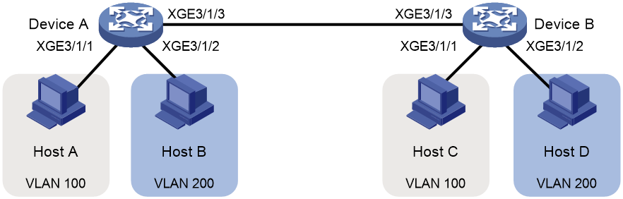
Network configuration
As shown in Figure 2:
· Host A and Host C belong to Department A. VLAN 100 is assigned to Department A.
· Host B and Host D belong to Department B. VLAN 200 is assigned to Department B.
Configure port-based VLANs so that only hosts in the same department can communicate with each other.
Procedure
1. Configure Device A:
# Create VLAN 100, and assign Ten-GigabitEthernet 3/1/1 to VLAN 100.
<DeviceA> system-view
[DeviceA] vlan 100
[DeviceA-vlan100] port ten-gigabitethernet 3/1/1
[DeviceA-vlan100] quit
# Create VLAN 200, and assign Ten-GigabitEthernet 3/1/2 to VLAN 200.
[DeviceA] vlan 200
[DeviceA-vlan200] port ten-gigabitethernet 3/1/2
[DeviceA-vlan200] quit
# Configure Ten-GigabitEthernet 3/1/3 as a trunk port, and assign the port to VLANs 100 and 200.
[DeviceA] interface ten-gigabitethernet 3/1/3
[DeviceA-Ten-GigabitEthernet3/1/3] port link-type trunk
[DeviceA-Ten-GigabitEthernet3/1/3] port trunk permit vlan 100 200
Please wait... Done.
2. Configure Device B in the same way Device A is configured. (Details not shown.)
3. Configure hosts:
a. Configure Host A and Host C to be on the same IP subnet. For example, 192.168.100.0/24.
b. Configure Host B and Host D to be on the same IP subnet. For example, 192.168.200.0/24.
Verifying the configuration
# Verify that Host A and Host C can ping each other, but they both fail to ping Host B and Host D. (Details not shown.)
# Verify that Host B and Host D can ping each other, but they both fail to ping Host A and Host C. (Details not shown.)
# Verify that VLANs 100 and 200 are correctly configured on Device A.
[DeviceA-Ten-GigabitEthernet3/1/3] display vlan 100
VLAN ID: 100
VLAN type: Static
Route interface: Not configured
Description: VLAN 0100
Name: VLAN 0100
Tagged ports:
Ten-GigabitEthernet3/1/3
Untagged ports:
Ten-GigabitEthernet3/1/1
[DeviceA-Ten-GigabitEthernet3/1/3] display vlan 200
VLAN ID: 200
VLAN type: Static
Route interface: Not configured
Description: VLAN 0200
Name: VLAN 0200
Tagged ports:
Ten-GigabitEthernet3/1/3
Untagged ports:
Ten-GigabitEthernet3/1/2
Configuring super VLANs
About super VLANs
Hosts in a VLAN typically use IP addresses in the same subnet. For Layer 3 interoperability with other VLANs, you can create a VLAN interface for the VLAN and assign an IP address to it. This requires a large number of IP addresses.
The super VLAN feature was introduced to save IP addresses. A super VLAN is associated with multiple sub-VLANs. These sub-VLANs use the VLAN interface of the super VLAN (also known as a super VLAN interface) as the gateway for Layer 3 communication.
You can create a VLAN interface for a super VLAN and assign an IP address to it. However, you cannot create a VLAN interface for a sub-VLAN. You can assign a physical port to a sub-VLAN, but you cannot assign a physical port to a super VLAN. Sub-VLANs are isolated at Layer 2.
To enable Layer 3 communication between sub-VLANs, perform the following tasks:
1. Create a super VLAN and the VLAN interface for the super VLAN.
2. Enable local proxy ARP or ND on the super VLAN interface as follows:
¡ In an IPv4 network, enable local proxy ARP on the super VLAN interface. The super VLAN can then process ARP requests and replies sent from the sub-VLANs.
¡ In an IPv6 network, enable local proxy ND on the super VLAN interface. The super VLAN can then process the NS and NA messages sent from the sub-VLANs.
Restrictions and guidelines: Super VLAN configuration
· Do not configure a VLAN as both a super VLAN and a sub-VLAN.
· Layer 2 multicast configuration for super VLANs does not take effect because they do not have physical ports.
Super VLAN tasks at a glance
To configure a super VLAN, perform the following tasks:
3. Configuring a super VLAN interface
Creating a sub-VLAN
1. Enter system view.
system-view
2. Create a sub-VLAN.
vlan vlan-id
By default, only the system default VLAN (VLAN 1) exists.
Configuring a super VLAN
1. Enter system view.
system-view
2. Enter VLAN view.
vlan vlan-id
3. Configure the VLAN as a super VLAN.
supervlan
By default, a VLAN is not a super VLAN.
4. Associate the super VLAN with the sub-VLANs.
subvlan vlan-id-list
Make sure the sub-VLANs already exist before associating them with a super VLAN.
Configuring a super VLAN interface
Restrictions and guidelines
As a best practice, do not configure VRRP for a super VLAN interface because the configuration affects network performance. For more information about VRRP, see High Availability Configuration Guide.
Procedure
1. Enter system view.
system-view
2. Create a VLAN interface and enter its view.
interface vlan-interface interface-number
The value for the interface-number argument must be the super VLAN ID.
3. Configure an IP address for the super VLAN interface.
¡ Configure an IPv4 address.
ip address ip-address { mask-length | mask } [ sub ]
¡ Configure an IPv6 address.
ipv6 address { ipv6-address prefix-length | ipv6-address/prefix-length }
By default, no IP address is configured for a VLAN interface.
4. Configure Layer 3 communication between sub-VLANs.
¡ Enable local proxy ARP for devices that run IPv4 protocols.
local-proxy-arp enable
¡ Enable local proxy ND for devices that run IPv6 protocols.
local-proxy-nd enable
By default:
¡ Sub-VLANs cannot communicate with each other at Layer 3.
¡ Local proxy ARP or ND is disabled.
For more information about local proxy ARP and ND, see Layer 3—IP Services Configuration Guide.
Display and maintenance commands for super VLANs
Execute display commands in any view.
|
Task |
Command |
|
Display information about super VLANs and their associated sub-VLANs. |
display supervlan [ supervlan-id ] |
Super VLAN configuration examples
Example: Configuring a super VLAN
Network configuration
As shown in Figure 3:
· Ten-GigabitEthernet 3/1/1 and Ten-GigabitEthernet 3/1/2 are in VLAN 2.
· Ten-GigabitEthernet 3/1/3 and Ten-GigabitEthernet 3/1/4 are in VLAN 3.
· Ten-GigabitEthernet 3/1/5 and Ten-GigabitEthernet 3/1/6 are in VLAN 5.
To save IP addresses and enable sub-VLANs to be isolated at Layer 2 but interoperable at Layer 3, perform the following tasks:
· Create a super VLAN and assign an IP address to its VLAN interface.
· Associate the super VLAN with VLANs 2, 3, and 5.
Procedure
# Create VLAN 10.
<DeviceA> system-view
[DeviceA] vlan 10
[DeviceA-vlan10] quit
# Create VLAN-interface 10, and assign IP address 10.1.1.1/24 to it.
[DeviceA] interface vlan-interface 10
[DeviceA-Vlan-interface10] ip address 10.1.1.1 255.255.255.0
# Enable local proxy ARP.
[DeviceA-Vlan-interface10] local-proxy-arp enable
[DeviceA-Vlan-interface10] quit
# Create VLAN 2, and assign Ten-GigabitEthernet 3/1/1 and Ten-GigabitEthernet 3/1/2 to the VLAN.
[DeviceA] vlan 2
[DeviceA-vlan2] port ten-gigabitethernet 3/1/1 ten-gigabitethernet 3/1/2
[DeviceA-vlan2] quit
# Create VLAN 3, and assign Ten-GigabitEthernet 3/1/3 and Ten-GigabitEthernet 3/1/4 to the VLAN.
[DeviceA] vlan 3
[DeviceA-vlan3] port ten-gigabitethernet 3/1/3 ten-gigabitethernet 3/1/4
[DeviceA-vlan3] quit
# Create VLAN 5, and assign Ten-GigabitEthernet 3/1/5 and Ten-GigabitEthernet 3/1/6 to the VLAN.
[DeviceA] vlan 5
[DeviceA-vlan5] port ten-gigabitethernet 3/1/5 ten-gigabitethernet 3/1/6
[DeviceA-vlan5] quit
# Configure VLAN 10 as a super VLAN, and associate sub-VLANs 2, 3, and 5 with the super VLAN.
[DeviceA] vlan 10
[DeviceA-vlan10] supervlan
[DeviceA-vlan10] subvlan 2 3 5
[DeviceA-vlan10] quit
[DeviceA] quit
Verifying the configuration
# Display information about super VLAN 10 and its associated sub-VLANs.
[DeviceA] display supervlan
Super VLAN ID: 10
Sub-VLAN ID: 2-3 5
VLAN ID: 10
VLAN type: Static
It is a super VLAN.
Route interface: Configured
Ipv4 address: 10.1.1.1
Ipv4 subnet mask: 255.255.255.0
Description: VLAN 0010
Name: VLAN 0010
Tagged ports: None
Untagged ports: None
VLAN ID: 2
VLAN type: Static
It is a sub VLAN.
Route interface: Configured
Ipv4 address: 10.1.1.1
Ipv4 subnet mask: 255.255.255.0
Description: VLAN 0002
Name: VLAN 0002
Tagged ports: None
Untagged ports:
Ten-GigabitEthernet3/1/1
Ten-GigabitEthernet3/1/2
VLAN ID: 3
VLAN type: Static
It is a sub VLAN.
Route interface: Configured
Ipv4 address: 10.1.1.1
Ipv4 subnet mask: 255.255.255.0
Description: VLAN 0003
Name: VLAN 0003
Tagged ports: None
Untagged ports:
Ten-GigabitEthernet3/1/3
Ten-GigabitEthernet3/1/4
VLAN ID: 5
VLAN type: Static
It is a sub VLAN.
Route interface: Configured
Ipv4 address: 10.1.1.1
Ipv4 subnet mask: 255.255.255.0
Description: VLAN 0005
Name: VLAN 0005
Tagged ports: None
Untagged ports:
Ten-GigabitEthernet3/1/5
Ten-GigabitEthernet3/1/6
