- Table of Contents
- Related Documents
-
| Title | Size | Download |
|---|---|---|
| 02-H3C iFIST CPU and Memory Diagnostics Configuration Examples | 1.51 MB |
H3C iFIST
CPU and Memory Diagnostics Configuration Examples
Copyright © 2023 New H3C Technologies Co., Ltd. All rights reserved.
No part of this manual may be reproduced or transmitted in any form or by any means without prior written consent of New H3C Technologies Co., Ltd.
Except for the trademarks of New H3C Technologies Co., Ltd., any trademarks that may be mentioned in this document are the property of their respective owners.
The information in this document is subject to change without notice.
Contents
Example: Configuring iFIST CPU and memory diagnostics
Viewing CPU and memory information
Performing fast diagnostics on CPU and memory
Performing stress tests on CPU and memory
Introduction
This document provides examples for using the iFIST diagnostics feature to scan and collect the information of server components, including BIOS, HDM, CPU, memory, drive, storage controller, logical drive, NIC, GPU, other PCIe devices, PSU, fan, and temperature sensor. The iFIST diagnostics feature also supports CPU and memory performance and health diagnostics.
Prerequisites
Procedures and information in the examples might be slightly different depending on the software or hardware version of the products.
The configuration was created and verified in a lab environment, and all the servers and software were started with the factory default configuration. If the device has been configured, ensure that the existing configuration does not conflict with the configuration in the following example.
This document assumes that you have basic knowledge of the iFIST server diagnostics feature.
Example: Configuring iFIST CPU and memory diagnostics
Network requirement:
As shown in Figure 1, connect the server’s HDM to the PC through a dedicated network port. This document uses the H3C UniServer R4700 G3 server as an example. Currently, the requirement is to access iFIST through HDM to diagnose the server CPU and memory.
· HDM management software:
¡ HDM management IP address: 10.99.205.163
¡ Default username: admin
¡ Default password: Password@_
· User PC:
¡ IP address: 10.99.162.6
¡ OS: Windows 7

Key steps
· iFIST scans the CPU and memory on the server.
· Verify whether the information of the CPU and memory is the same as that of the actual CPU and memory, and perform fast diagnostics and stress tests on them.
· Export related diagnostics data.
Software versions used
This configuration example was created and verified on iFIST 1.38.
Configuration procedure
Logging in to iFIST
1. Open a browser on a client PC, and then enter the HDM management IP address 10.99.205.163 to access the HDM login page, as shown in Figure 2. On the HDM login page, enter the default username admin and the default password Password@_, and then click Log In.

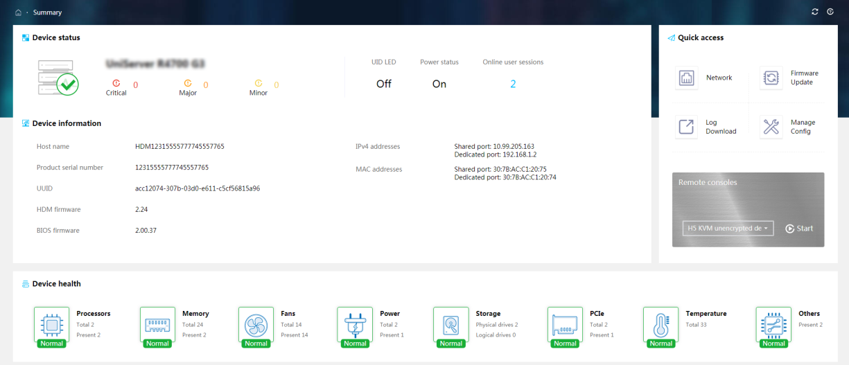
2. On the HDM home page, click Start to start the remote console, as shown in Figure 3.
Figure 3 Starting the remote console on HDM
3. On the H5 KVM page, click Power > Restart.
4. After the server is initialized, the boot screen is displayed. Press F10 to access iFIST, as shown in Figure 4.

Viewing CPU and memory information
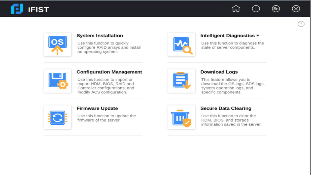
1. On the iFIST home page, click Intelligent Diagnostics > Server Diagnostics, as shown in Figure 5.
2. iFIST starts to scan the server, as shown in Figure 6.

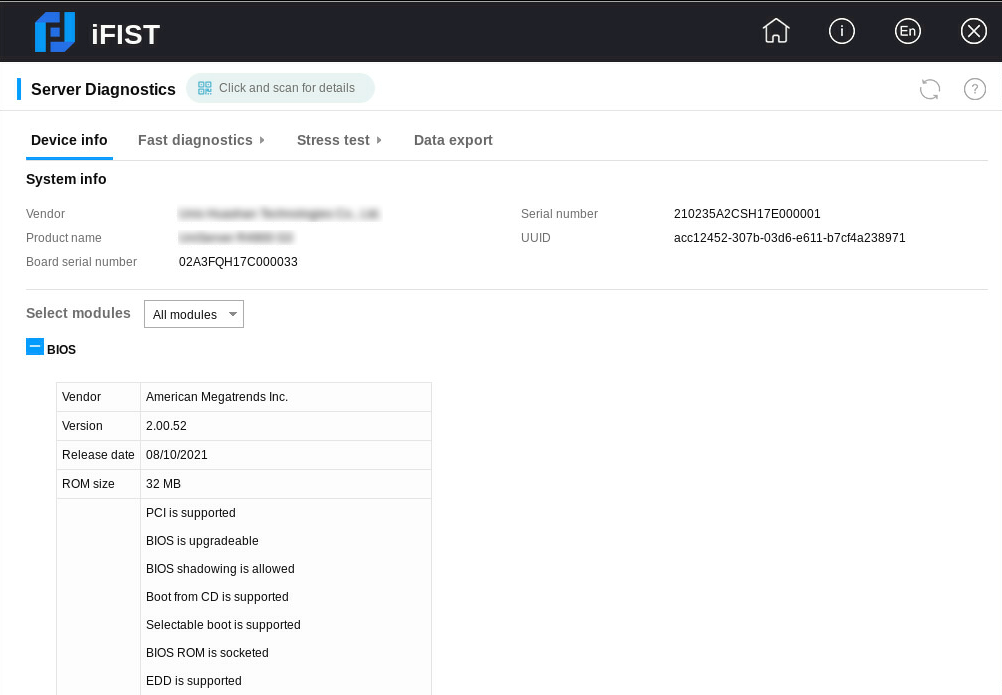
3. After the scanning is complete, the system jumps to the Device Info page shown in Figure 7.
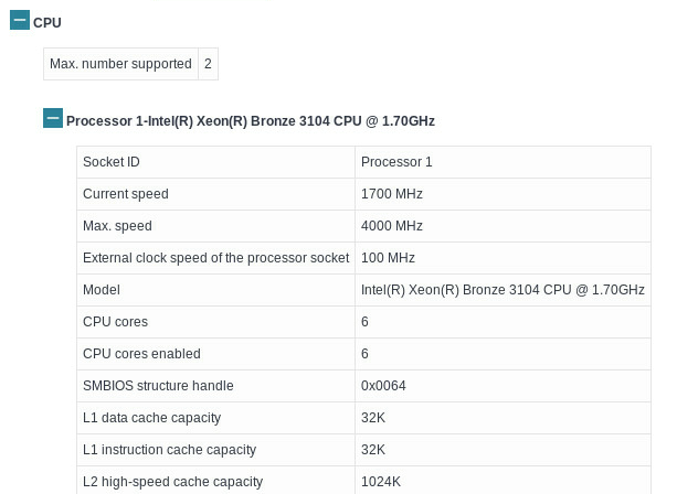
4. Select CPU from the Select modules list to view CPU information. The CPU information is shown in Figure 8.
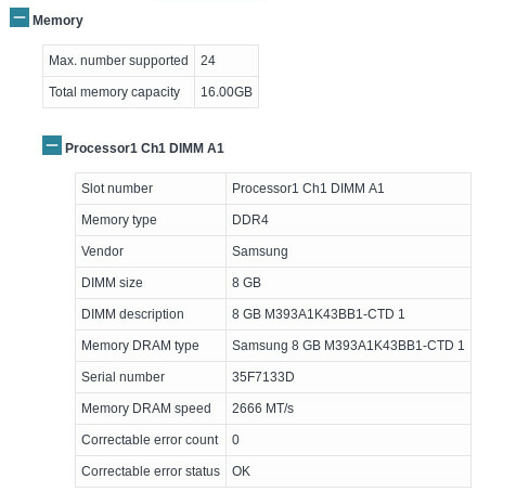
5. Select Memory from the Select modules list to view memory information. The memory information is shown in Figure 9.
Performing fast diagnostics on CPU and memory
Parameter configuration
1. On the server diagnostics page, select Fast diagnostics > Select configuration, as shown in Figure 10.

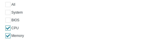
2. Select CPU and Memory in the Please select the components to diagnose column. Select the Stop diagnosing when the first error result comes out option as needed, as shown in Figure 11.
¡ CPU: Checks the number of CPUs on the server and available memory on each CPU, runs UPI and floating-point tests on the CPUs, and checks for machine check architecture (MCA) errors.
¡ Memory: Performs stress tests on memory using various algorithms, and checks for MCA errors.
Figure 11 Selecting the components to diagnose
3. Select the test mode. Options are Common test, Cyclic test, and Timed test, as shown in Figure 12.
¡ Common test: Tests the selected component once. In this example, this option is selected.
¡ Cyclic test: Specifies the test cycles. Value range: 1 to 999.
¡ Timed test: Specifies the time period for the test. Value range: 1 to 5760.
Figure 12 Selecting a test mode for fast diagnostics

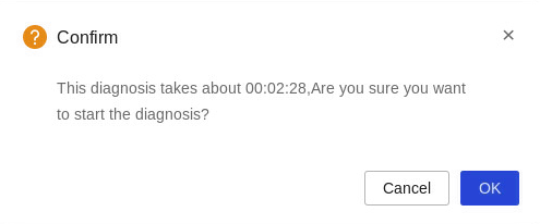
4. Click Start to start diagnosing the CPU and memory, as shown in Figure 13.
Viewing the diagnostic status
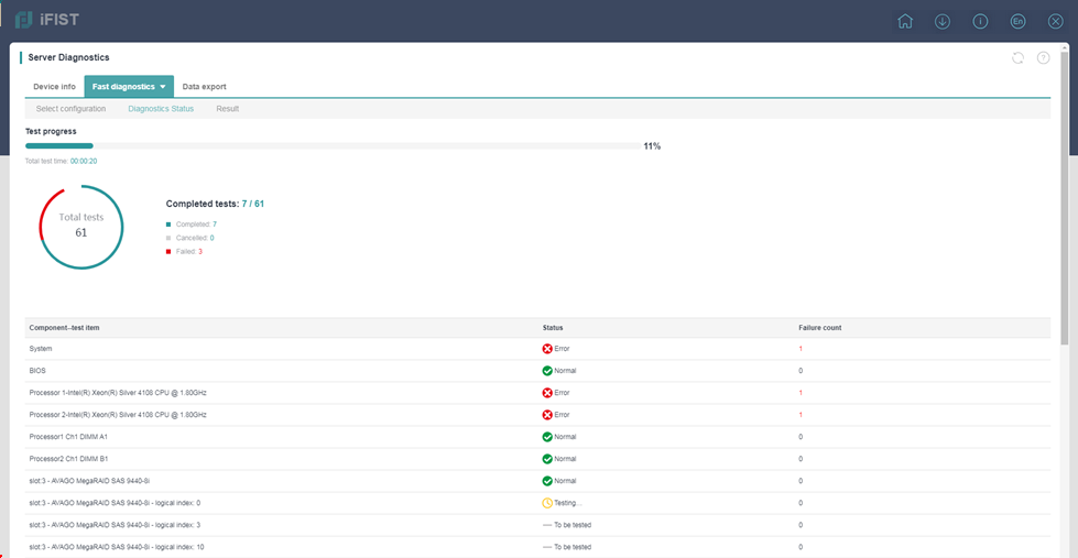
1. iFIST opens the Diagnostic status page upon the start of the diagnostic process, as shown in Figure 14. The page provides information about the ongoing diagnostic tests, including the test progress, summarized test item statistics, and CPU and memory diagnostic status.
Figure 14 Viewing the diagnostic status
Viewing the diagnostic result
After the fast diagnostics process is completed, click Result to view the diagnostic results. The Result tab displays the number of tests, test result, and error information for the CPU and memory, as shown in Figure 15.
Performing stress tests on CPU and memory
Parameter configuration
1. On the server diagnostics page, click Stress test > Select configuration, as shown in Figure 16.
Figure 16 Configuring stress test settings
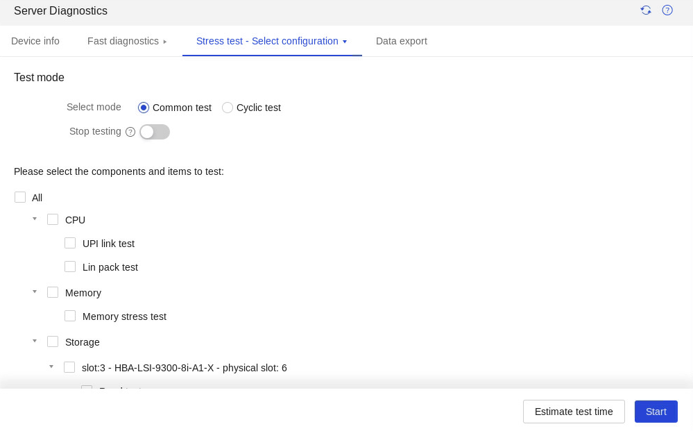
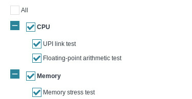
2. Select CPU and Memory in the Please select the components and items to test column. Select the Stop testing when the first error result comes out option as needed, as shown in Figure 17.
¡ UPI link test: Tests the transmission capability and transmission rate of Ultra Path Interconnect (UPI) and QuickPath Interconnect (QPI) links.
¡ Floating-point arithmetic test: Tests the floating-point arithmetic function of the CPU.
¡ Memory stress test: Tests the storage function of the memory by using multiple algorithms to test the memory storage units.
Figure 17 Configuring stress test settings
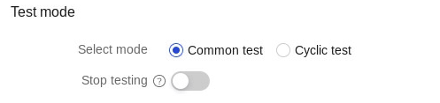
3. Select a test mode, as shown in Figure 18. Options:
¡ Common test: Tests the selected component once. In this example, this option is selected.
¡ Cyclic test: Specifies the test cycles. Value range: 1 to 999.
Figure 18 Selecting a test node for the stress test
4. Click Start to start testing the CPU and memory.
Viewing the test status
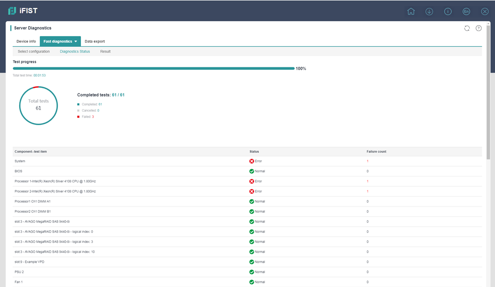
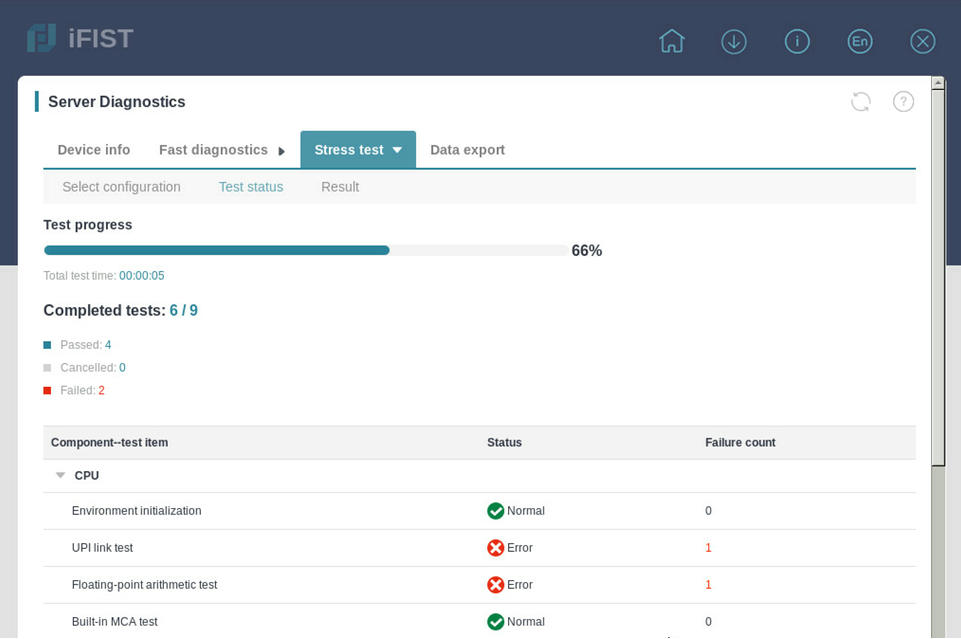
1. iFIST opens the Test status page upon the start of the test process, as shown in Figure 19. The page provides information about the ongoing tests, including the test progress, summarized test item statistics, and CPU and memory test status.
Figure 19 Viewing the test status
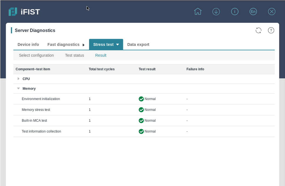
Viewing the test results
After the stress test is completed, click Result to view the test results. The Result tab displays the number of tests, test result, and error information for the CPU and memory, as shown in Figure 20.
Exporting data
1. On the server diagnostics page, click the Data export tab.
2. From the USB flash drive list, select the USB flash drive to which you want to export the data. At present, only USB flash drives using the FAT32 system can export data directly. For non-FAT32 USB flash drives, click Format to format it to FAT32, and then click OK in the dialog box that opens, as shown in Figure 21. Format the USB flash drive with caution because this operation will delete data in the USB flash drive.
Figure 21 Formatting the USB flash drive

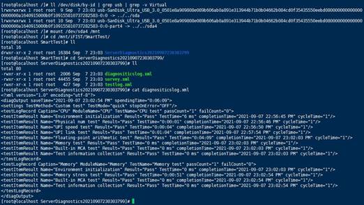
3. Click Export to export the test result to the specified USB flash drive. Device information will be exported to the iFIST/SmartTest directory in the root directory of the USB flash drive, as shown in Figure 22. If no such directory exists in the root directory, the system automatically creates one. File data in the USB flash drive is shown in Figure 23.
Figure 22 Exporting the test results to the USB flash drive

Figure 23 Data in the USB drive
Verifying the configuration
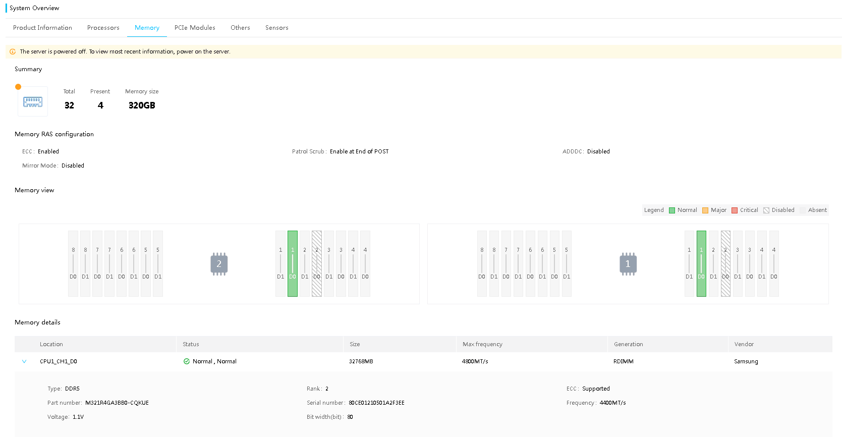
Log in to HDM, and then click System Management > System Info. On the page that opens, view the CPU and memory information and make sure the CPU and memory are in normal state, as shown in Figure 24 and Figure 25.
Figure 24 CPU information on HDM

Figure 25 Memory information on HDM
Related documentation
H3C iFIST Technology White Paper
H3C Servers iFIST User Guide
