- Table of Contents
- Related Documents
-
| Title | Size | Download |
|---|---|---|
| 03-Microsoft NPS Server Configuration Examples | 3.08 MB |
|
|
|
H3C Access Controllers |
|
Access Authentication by Microsoft NPS Server |
|
Configuration Examples |
|
|
Copyright © 2023 New H3C Technologies Co., Ltd. All rights reserved.
No part of this manual may be reproduced or transmitted in any form or by any means without prior written consent of New H3C Technologies Co., Ltd.
Except for the trademarks of New H3C Technologies Co., Ltd., any trademarks that may be mentioned in this document are the property of their respective owners.
The information in this document is subject to change without notice.
Contents
Example: Configuring portal authentication using the NPS authentication server
Example: Configuring remote 802.1X authentication using the NPS authentication server
Example: Configuring remote MAC authentication using the NPS authentication server
Introduction
The following information provides examples for configuring H3C access controllers to use authentication server software of Microsoft NPS to authenticate wireless clients. The examples include configuring Microsoft NPS-based portal authentication, 802.1X authentication, MAC authentication, and authorization ACL and VLAN assignment.
Software versions used
The following configuration examples were created and verified on the following hardware and software versions:
· AC: vAC running R5435P03.
· NPS authentication server: Windows Server 2016 NPS component.
· IMC server: Server running iMC PLAT 7.3 (E0706P03) and iMC 7.3 (E0620).
· Microsoft Windows Server 2012 Active Directory.
Example: Configuring portal authentication using the NPS authentication server
Network configuration
As shown in Figure 1, the AP is connected to the AC over the switch and the client accesses the wireless network through the AP.
Configure direct portal authentication to control the client's access to the network resources. Use the NPS server as the RADIUS server and the IMC server as the portal server.

Restrictions and guidelines
Use the serial ID labeled on the AP's rear panel to specify an AP.
Procedures
Configuring the AC
1. Configure a RADIUS scheme:
# Create RADIUS scheme nps.
<AC> system-view
[AC] radius scheme nps
# Specify the NPS server as the primary authentication and accounting server and specify a shared key for secure communication with the server. Make sure the shared key is the same as the shared secret configured on the NPS server.
[AC-radius-nps] primary authentication 8.72.1.7 key simple 12345678
[AC-radius-nps] primary accounting 8.72.1.7 key simple 12345678
# Exclude the domain name from usernames sent to the NPS server.
[AC-radius-nps] user-name-format without-domain
[AC-radius-nps] quit
2. Configure an ISP domain:
# Create ISP domain portal.
[AC] domain portal
# Configure the ISP domain to use RADIUS scheme nps for portal user authentication, authorization, and accounting.
[AC-isp-portal] authentication portal radius-scheme nps
[AC-isp-portal] authorization portal radius-scheme nps
[AC-isp-portal] accounting portal radius-scheme nps
[AC-isp-portal] quit
3. Configure portal authentication:
# Configure the portal authentication server name as imc, IP address as the IP address of the IMC server, and the key as portal in plaintext.
[AC] portal server imc
[AC-portal-server-imc] ip 8.1.1.231 key simple portal
[AC-portal-server-imc] quit
# Configure the portal Web server URL as http://8.1.1.231/portal/. (Please specify the URL of the real portal Web server.)
[AC] portal web-server imc
[AC-portal-websvr-imc] url http://8.1.1.231/portal/
[AC-portal-websvr-imc] quit
# Create service template portal.
[AC] wlan service-template portal
# Specify an SSID for the service template.
[AC-wlan-st-portal] ssid portal_nps
# Enable direct portal authentication on the service template.
[AC-wlan-st-portal] portal enable method direct
# Specify portal Web server imc on the service template.
[AC-wlan-st-portal] portal apply web-server imc
# Specify authentication domain portal on the service template.
[AC-wlan-st-portal] portal domain portal
# Enable the service template.
[AC-wlan-st-portal] service-template enable
[AC-wlan-st-portal] quit
# Configure a manual AP named ap1 and specify its model and serial ID.
[AC] wlan ap ap1 model WA6638-JP
[AC-wlan-ap-ap1] serial-id 219801A24F8198E0001G
[AC-wlan-ap-ap1] quit
# Enable radio 1 and bind service template portal and VLAN 80 to the radio.
[AC] wlan ap ap1
[AC-wlan-ap-ap1] radio 1
[AC-wlan-ap-ap1-radio-1] service-template portal vlan 80
[AC-wlan-ap-ap1-radio-1] radio enable
[AC-wlan-ap-ap1-radio-1] quit
[AC-wlan-ap-ap1] quit
4. Configure ACL 3999. (Configure the ACL as needed.)
[AC] acl advanced 3999
[AC-acl-ipv4-adv-3999] rule 0 permit ip
[AC-acl-ipv4-adv-3999] quit
5. Enable the DHCP service on the AC, create a DHCP address pool to assign an IP address to the client:
# Create VLAN 80 and VLAN-interface 80. Assign IP address 72.205.1.1 and subnet mask 255.255.0.0 to the VLAN interface.
[AC] vlan 80
[AC-vlan80] quit
[AC] interface Vlan-interface 80
[AC-Vlan-interface80] ip address 72.205.1.1 255.255.0.0
[AC-Vlan-interface80] quit
# Enable the DHCP service.
[AC] dhcp enable
# Create a DHCP address pool named 80.
[AC] dhcp server ip-pool 80
[AC-dhcp-pool-80] quit
# In the DHCP address pool, specify the subnet for dynamic allocation as 72.205.0.0/16.
[AC-dhcp-pool-80] network 72.205.0.0 mask 255.255.0.0
# Specify the gateway address as 72.205.1.1 in the DHCP address pool.
[AC-dhcp-pool-80] gateway-list 72.205.1.1
# Specify the DNS server address as 72.205.1.1 in the DHCP address pool.
[AC-dhcp-pool-80] dns-list 72.205.1.1
[AC-dhcp-pool-80] quit
Configuring the IMC server (portal server)
1. Configure the portal server:
a. Log in to IMC and click the User tab.
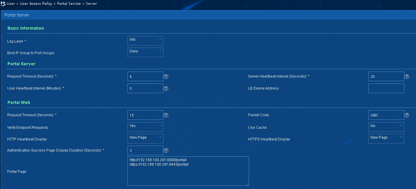
b. Select User Access Policy > Portal Service > Server from the navigation tree to open the portal server configuration page, as shown in Figure 2.
c. Configure the portal server parameters as needed.
d. Click OK.
Figure 2 Portal server configuration
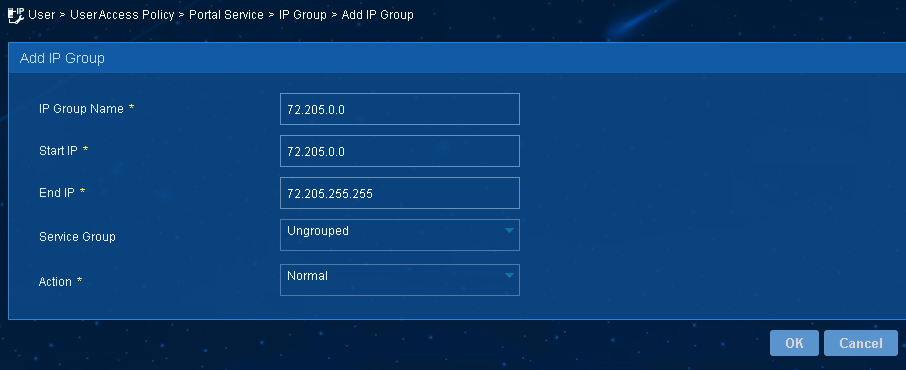
2. Configure the IP address group:
a. Select User Access Policy > Portal Service > IP Group from the navigation tree to open the portal IP address group configuration page.
b. Click Add to open the page as shown in Figure 3.
c. Enter the start IP address and end IP address of the IP group.
Make sure the client IP address is in the IP group.
d. Select a service group.
This example uses the default group Ungrouped.
e. Select Normal from the Action list.
f. Click OK.
Figure 3 Adding an IP address group
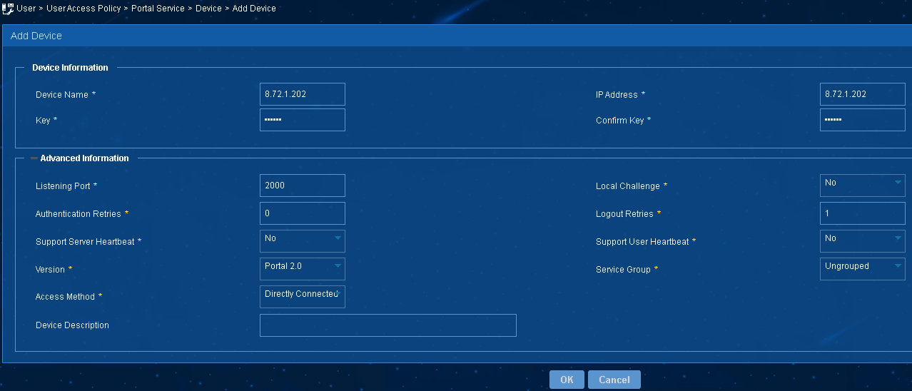
3. Add a portal device:
a. Select User Access Policy > Portal Service > Device from the navigation tree to open the portal device configuration page.
b. Click Add to open the page as shown in Figure 4.
c. Enter the device name (name of the AC).
d. Enter the IP address of the AC's interface that exchanges information with the portal server.
e. Enter the key, which must be the same as that configured on the AC. In this example, it is portal.
f. Select Directly Connected from the Access Method list.
g. Use the default settings for other parameters.
h. Click OK.
Figure 4 Adding a portal device
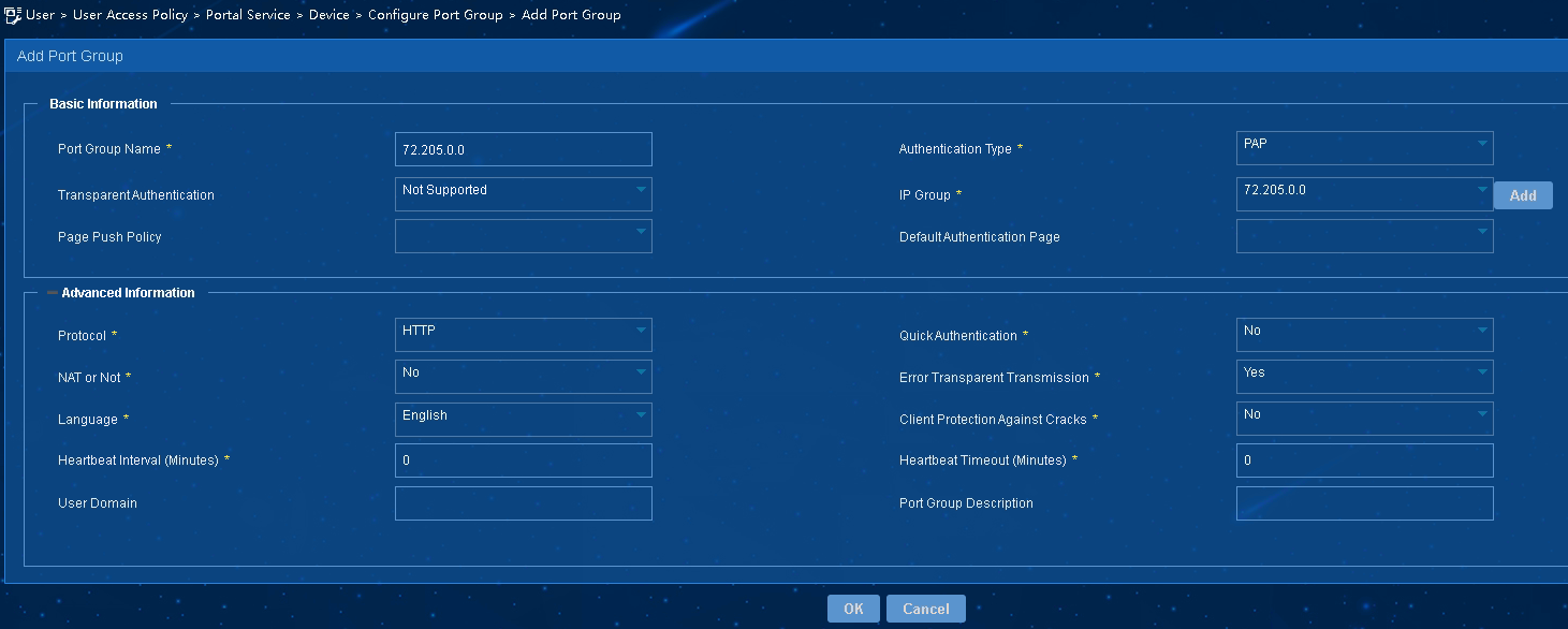
4. Associate the portal device with the IP address group:
a. As shown in Figure 5, click
the Port Group Information Management icon ![]() for the device to open the port group configuration page.
for the device to open the port group configuration page.
b. Click Add to open the page as shown in Figure 6.
c. Enter the port group name.
d. Select PAP as the authentication type.
e. Select the configured IP address group.
The IP address used by the user to access the network must be within this IP address group.
f. Use the default settings for other parameters.
g. Click OK.
Configuring the NPS server (RADIUS server)
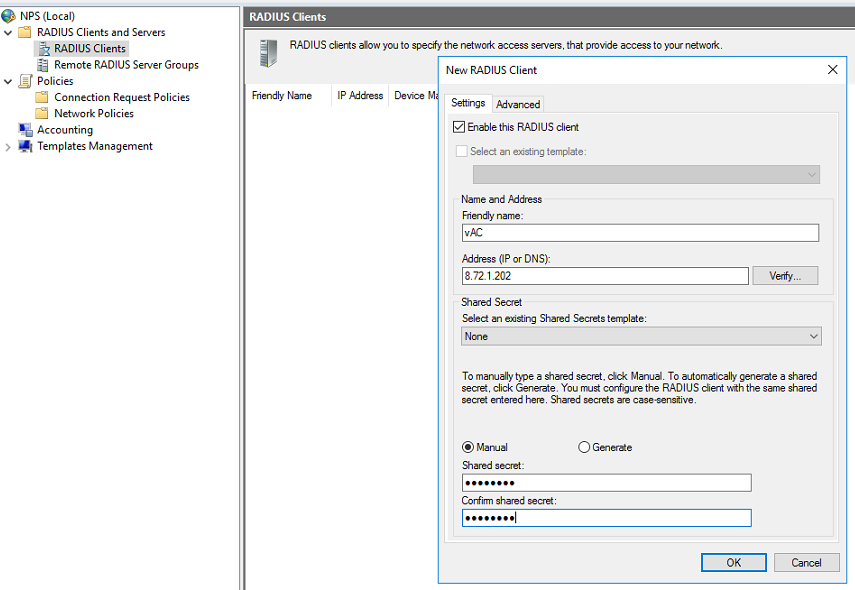
1. Configure the RADIUS client:
a. Open the Network Policy Server (NPS) component. In the left navigation pane, select RADIUS Client and Servers > RADIUS Clients.
b. Add a new RADIUS client: Enter the IP address of the AC in the Address (IP or DNS) field. Enter the shared secret, which must be the same as the shared key configured for the primary authentication and accounting server. In this example, the shared secrete is 12345678.
c. Click OK.
Figure 7 Creating a RADIUS client
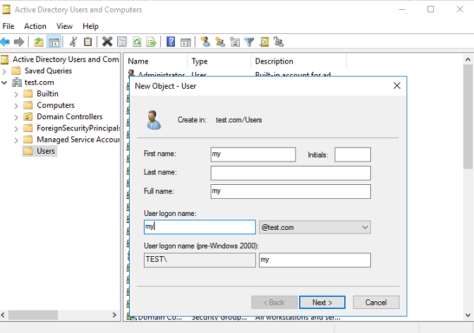
2. Create a user:
a. Open the Active Directory Users and Computers component. Select the Users directory and then right-click it to add a new user.
b. Configure the username as my, and then click Next.
Figure 8 Creating a user
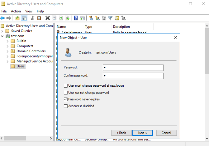
c. Configure the user password, select Password never expires, and then click Next.
Figure 9 Configuring the user password
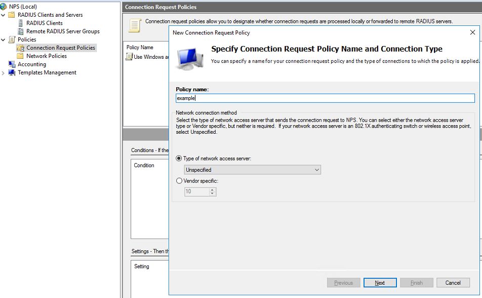
3. Configure a connection request policy:
a. Add a new connection request policy:
# Open the NPS component. Select Policies > Connection Request Policies from the navigation pane.
# Add a request policy: configure the policy name, use the default settings for other options, and then click Next.
Figure 10 Creating a connection request policy
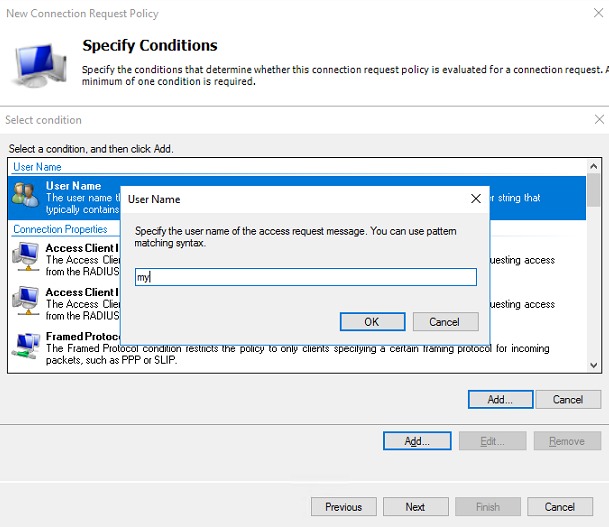
b. Add a user name:
# On the Specify Conditions page, select User Name, and then click Add to add the RADIUS user added in the previous step to the connection request policy.
# Click OK.
Figure 11 Adding a user name
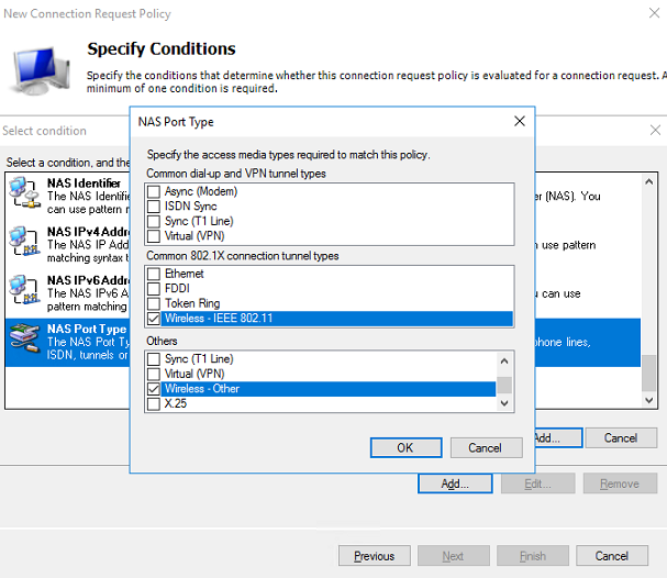
c. Configure the NAS port type:
# In the bottom part of the Specify Conditions page, select NAS Port Type, and then click Add to add the selected types to the connection request policy.
# In the Common 8021.X connection tunnel types area, select Wireless IEEE – 802.11. In the Others area, select Wireless – Other.
# Click OK.
Figure 12 Configuring NAS Port Type
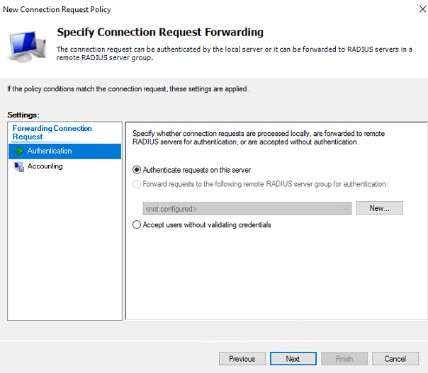
# Click Next to open the Specify Connection Request Forwarding page.
d. Configure the identity authentication location:
# On the Specify Connection Request Forwarding page, select Authentication, and then select Authenticate requests on this server.
Figure 13 Configuring identity authentication location
# Click Next to open the Specify Authentication Methods page.
a. Specify authentication methods:
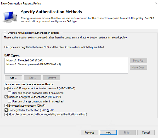
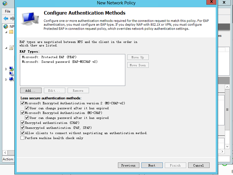
# In the EAP Types box, add Protected EAP (PEAP) and Secured password (EAP-MSCHAP v2).
# In the Less secure authentication methods area, select Microsoft Encrypted Authentication version 2 (MS-CHAP-v2), Microsoft Encrypted Authentication (MS-CHAP), Encrypted authentication (CHAP), Unencrypted authentication (PAP.SPAP), and Allow clients to connect without negotiating an authentication method.
Figure 14 Specifying authentication methods
# Click Next.
# In the window that opens, click No to open the Configure Settings page.
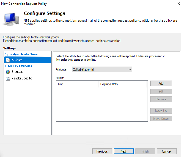
f. Configure the policy attribute: Select Called-Station-Id from the Attribute list.
Figure 15 Configuring the policy attribute
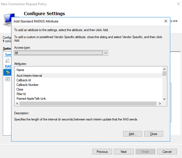
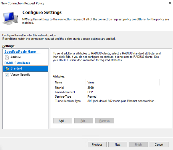
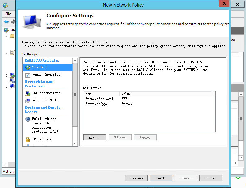
g. Add standard RADIUS attributes:
# Select Standard for RADIUS Attributes.
# In the Attributes column, select an attribute name, and then click Add. The Attribute Information dialog box opens.
Figure 16 Adding a standard RADIUS attribute
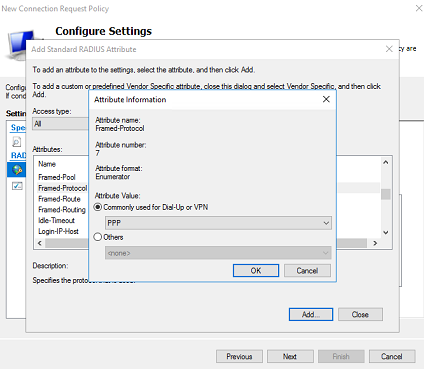
# In the Attribute Information dialog box that opens, configure the attribute value.
# Keep the default selection for the attribute, select the attribute value from the drop-down list, and then click OK.
For example, for the Framed-Protocol attribute, the Commonly used for Dial-Up or VPN option is selected by default. Keep this default selection and then select PPP from the drop-down list, and then click OK. The attribute value PPP is configured for the Framed-Protocol attribute.
Figure 17 Configuring the attribute value
# Repeat the previous steps to add the Service-Type attribute with value Framed, the Tunnel-Media-Type attribute with value 802 (include all 802 media plus Ethernet…), and the Filter-Id attribute with value 3999 (an ACL). The configured attributes are listed as follows:
Figure 18 Standard RADIUS attributes
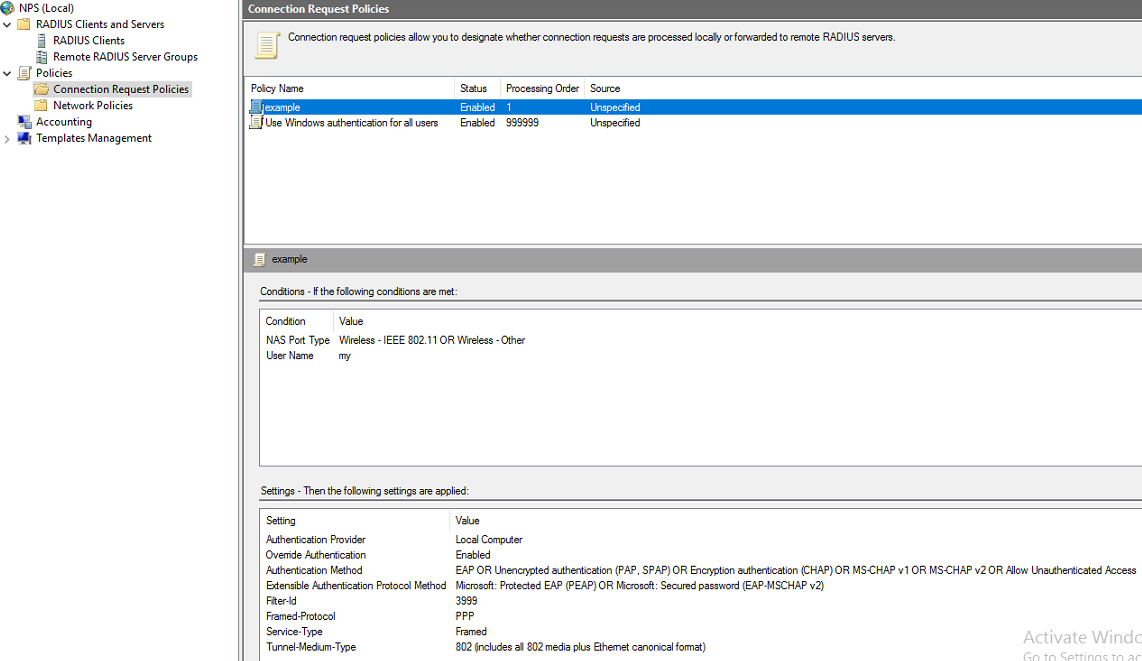
h. View or edit the connection request policy:
# Select Policies > Connection Request Policies from the left navigation pane of NPS.
# In the Policy Name column, you can view the connection request policies.
# To edit the configuration for a policy, right-click the policy name and select Properties.
Figure 19 Connection request policies
Verifying the configuration
1. On the client, connect to the wireless network. Access a website by using a browser. The portal authentication page is opened. Enter the configured username my and password. The user can successfully pass the authentication.
2. On the AC, verify that the user has come online and the server has assigned the authorization ACL to the user by using the following command:
[AC] display portal user all verbose
Total portal users: 1
Basic:
AP name: ap1
Radio ID: 1
SSID: portal_nps
Current IP address: 72.205.0.1
Original IP address: 72.205.0.1
Username: my
User ID: 0x1000002b
Access interface: WLAN-BSS0/4
Service-VLAN/Customer-VLAN: 80/-
MAC address: d4bb-c8a1-8a55
Authentication type: Normal
Domain name: portal
VPN instance: N/A
Status: Online
Portal server: imc
Vendor: VIVO
Portal authentication method: Direct
AAA:
Realtime accounting interval: 720s, retry times: 5
Idle cut: N/A
Session duration: 0 sec, remaining: 0 sec
Remaining traffic: N/A
Login time: 2021-12-3 18:57:44 UTC
Online time(hh:mm:ss): 00:00:05
DHCP IP pool: N/A
Web URL: N/A
ACL&QoS&Multicast:
Inbound CAR: N/A
Outbound CAR: N/A
ACL number: 3999 (active, AAA)
User profile: N/A
Session group profile: N/A
Max multicast addresses: 4
Flow statistic:
Uplink packets/bytes: 7/540
Downlink packets/bytes: 0/0
Configuration files
#
radius scheme nps
primary authentication 8.72.1.7 key simple 12345678
primary accounting 8.72.1.7 key simple 12345678
user-name-format without-domain
#
domain portal
authentication portal radius-scheme nps
authorization portal radius-scheme nps
accounting portal radius-scheme nps
#
portal server imc
ip 8.1.1.231 key simple portal
#
portal web-server imc
url http://8.1.1.231/portal/
#
wlan service-template portal
ssid portal_nps
portal enable method direct
portal domain portal
portal apply web-server imc
service-template enable
#
wlan ap ap1 model WA6638-JP
serial-id 219801A24F8198E0001G
radio 1
radio enable
service-template portal vlan 80
#
acl advanced 3999
rule 0 permit ip
#
vlan 80
#
interface Vlan-interface 80
ip address 72.205.1.1 255.255.0.0
#
dhcp server ip-pool 80
gateway-list 72.205.1.1
network 72.205.0.0 mask 255.255.0.0
dns-list 72.205.1.1
#
Return
Example: Configuring remote 802.1X authentication using the NPS authentication server
Network configuration
As shown in Figure 20, the AP is connected to the AC over the switch and the client accesses the wireless network through the AP.
Configure 802.1X authentication in EAP relay mode to control the client's access to the network resources. Use the NPS server as the RADIUS server and 802.1X authentication server.

Restrictions and guidelines
Use the serial ID labeled on the AP's rear panel to specify an AP.
Procedures
Configuring the AC
1. Configure an ISP domain:
# Create ISP domain nps.
<H3C> system-view
[H3C] domain nps
# Configure the ISP domain to use RADIUS scheme nps for LAN user authentication, authorization, and accounting.
[H3C-isp-nps] authentication lan-access radius-scheme nps
[H3C-isp-nps] authorization lan-access radius-scheme nps
[H3C-isp-nps] accounting lan-access radius-scheme nps
[H3C-isp-nps] quit
2. Configure a RADIUS scheme:
# Create RADIUS scheme nps.
[H3C] radius scheme nps
# Specify the NPS server as the primary authentication and accounting server and specify a shared key for secure communication with the server. Make sure the shared key is the same as the shared secret configured on the NPS server.
[H3C-radius-nps] primary authentication 192.168.106.40 key simple 12345678
[H3C-radius-nps] primary accounting 192.168.106.40 key simple 12345678
# Specify a NAS-IP for outgoing RADIUS packets.
[H3C-radius-nps] nas-ip 192.168.105.190
[H3C-radius-nps] quit
3. Configure the AC to use EAP relay to authenticate the 802.1X client.
[H3C] dot1x authentication-method eap
4. Configure a service template:
# Create service template nps.
[H3C]wlan service-template nps
# Specify an SSID for the service template.
[H3C-wlan-st-nps] ssid h3c-nps-dot1x
# Set the AKM mode to 802.1X.
[H3C-wlan-st-nps] akm mode dot1x
# Specify the AES-CCMP cipher suite, and enable the RSN IE in beacon and probe responses.
[H3C-wlan-st-nps] cipher-suite ccmp
[H3C-wlan-st-nps] security-ie rsn
# Set the authentication mode to 802.1X authentication and specify authentication domain nps.
[H3C-wlan-st-nps] client-security authentication-mode dot1x
[H3C-wlan-st-nps] dot1x domain nps
# Assign clients coming online through the service template to VLAN 1000.
[H3C-wlan-st-nps] vlan 1000
# Configure the AC to forward client data traffic. Skip this step if the AC forwards client data traffic by default.
[H3C-wlan-st-nps] client forwarding-location ac
# Enable the service template.
[H3C-wlan-st-nps] service-template enable
5. Bind the service template to radio 1.
[H3C]wlan ap ap1 model WA6330
[H3C-wlan-ap-ap1] serial-id 219801A23V8209E0043Y
[H3C-wlan-ap-ap1] radio 1
[H3C-wlan-ap-ap1] radio enable
[H3C-wlan-ap-ap1] service-template nps
[H3C-wlan-ap-ap1] quit
6. Configure ACL 3000. (Configure the ACL as needed.)
[H3C] acl advanced 3000
[H3C-acl-ipv4-adv-3000] rule 0 permit ip
7. Configure interfaces on the AC:
# Create VLAN 1000 and VLAN-interface 1000, and assign an IP address and mask to the VLAN interface.
[H3C] vlan 1000
[H3C-vlan1000] quit
[H3C] interface Vlan-interface 1000
[H3C-Vlan-interface1000] ip address 1.1.1.1 255.255.255.0
[H3C-Vlan-interface1000] quit
# Enable the DHCP service.
[H3C] dhcp enable
# Create a DHCP address pool named 1000.
[H3C] dhcp server ip-pool 1000
[H3C-dhcp-pool-1000] quit
# Specify primary subnet 1.1.1.0/24 for dynamic allocation in the DHCP address pool.
[H3C-dhcp-pool-1000] network 1.1.1.0 mask 255.255.255.0
# Specify gateway address 1.1.1.1.
[H3C-dhcp-pool-1000] gateway-list 1.1.1.1
# Specify DNS server address 1.1.1.1 in the DHCP address pool.
[H3C-dhcp-pool-1000] dns-list 1.1.1.1
[H3C-dhcp-pool-1000] quit
# Create VLAN-interface 1 and assign an IP address to the VLAN interface.
[H3C] interface Vlan-interface 1
[H3C-Vlan-interface1] ip address 192.168.105.190 255.255.255.0
[H3C-Vlan-interface1] quit
# Set the link type of GigabitEthernet 1/0/1 (the interface connected to the switch) to trunk, and assign the interface to VLAN 1 and VLAN 1000.
[H3C] interface gigabitethernet 1/0/1
[H3C-GigabitEthernet1/0/1] port link-type trunk
[H3C-GigabitEthernet1/0/1] port trunk permit vlan 1 1000
[H3C-GigabitEthernet1/0/1] quit
Configuring the switch
# Create VLAN 1000 for forwarding client wireless packets.
[Switch] vlan 1000
[Switch-vlan1000] quit
# Create VLAN-interface 1000 and assign an IP address to the VLAN interface.
[Switch] interface vlan-interface 1000
[Switch-Vlan-interface1000] ip address 1.1.1.2 255.255.255.0
[Switch-Vlan-interface1000] quit
# Set the link type of GigabitEthernet 1/0/1 (the interface connected to the AC) to trunk, and assign the interface to VLAN 1 and VLAN 1000.
[Switch] interface gigabitethernet 1/0/1
[Switch-GigabitEthernet1/0/1] port link-type trunk
[Switch-GigabitEthernet1/0/1] port trunk permit vlan 1 1000
[Switch-GigabitEthernet1/0/1] quit
# Set the link type of GigabitEthernet 1/0/2 (the interface connected to the AP) to access.
[Switch] interface gigabitethernet 1/0/2
[Switch-GigabitEthernet1/0/2] port link-type access
Adding a user account on the NPS server
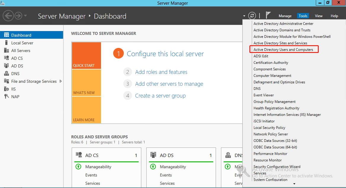
1. On the NPS server, select Start > Control Panel > Administrative Tools, and then double-click Active Directory Users and Computers.
The Active Directory Users and Computers window is displayed.
Figure 21 Active Directory Users and Computers window
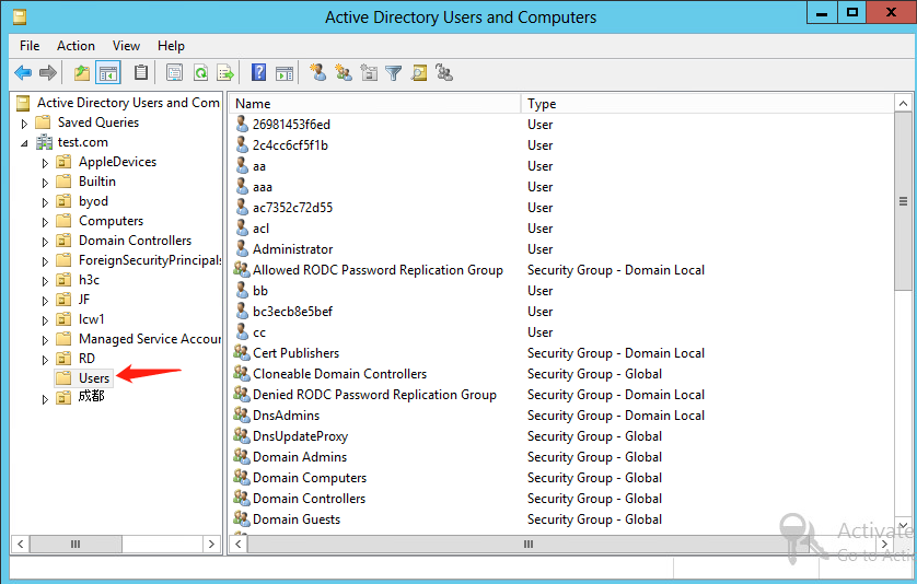
2. From the navigation pane, click Users under the test.com node.
Figure 22 Users window
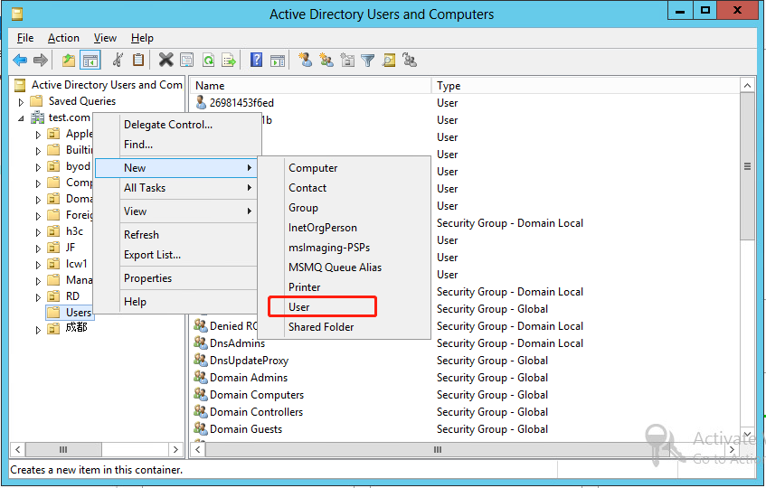
3. Right-click Users, and select New > User from the shortcut menu to display the dialog box for adding a user.
Figure 23 Users options
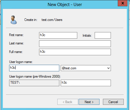
4. In the dialog box, set the first name, full name, and user logon name to h3c, and then click Next.
Figure 24 Entering the first name, full name, and user logon name
5. In the dialog box that opens, configure and confirm the password of the user, select options as needed, and click Next.
Figure 25 Setting the user's password
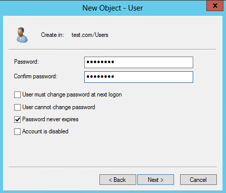
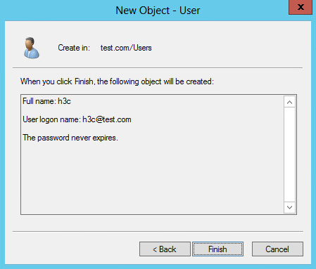
Figure 26 Finishing creating the user
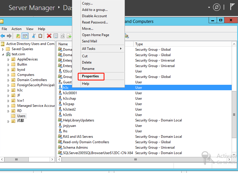
6. From the navigation pane, click Users under the test.com node. In the right pane, right-click user h3c and select Properties.
Figure 27 Selecting the Properties option for the user
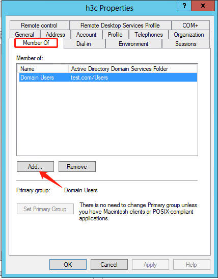
7. In the dialog box that opens, click the Member Of tab, select the Domain Users primary group, and then click Add.
Figure 28 Adding a primary group
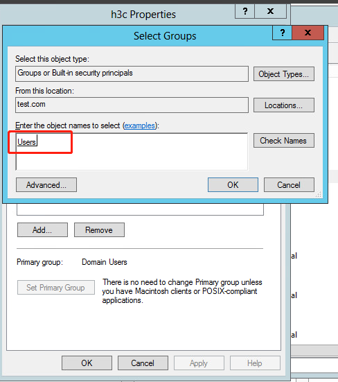
8. In the Select Groups dialog box, enter Users in the Enter the object names to select field, and click OK.
User h3c is added to group Users.
Figure 29 Adding user h3c to group Users
Configuring the NPS server (RADIUS server)
1. Configure the RADIUS client:
a. Open the Network Policy Server (NPS) component. In the left navigation pane, select RADIUS Client and Servers > RADIUS Clients.
b. Add a new RADIUS client: Enter the IP address of the AC in the Address (IP or DNS) field, which is 192.168.105.190. Enter the shared secret, which must be the same as the shared key configured for the primary authentication and accounting server. In this example, the shared secret is 12345678.
Figure 30 Creating a RADIUS client

2. Configure a connection request policy:
a. Add a new connection request policy:
# Select Policies > Connection Request Policies from the navigation pane.
# Right-click Connection Request Policies and select to create a request policy.
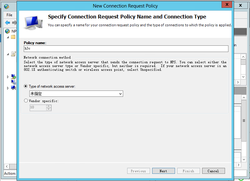
# Configure the policy name as h3c, use the default settings for other options, and then click Next.
Figure 31 Creating a connection request policy
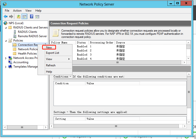
Figure 32 Configuring the policy name
b. Configure the NAS port type:
# In the bottom part of the Specify Conditions page, select NAS Port Type, and then click Add to add the selected types to the connection request policy.
# In the Common 8021.X connection tunnel types area, select Wireless IEEE – 802.11. In the Others area, select Wireless – Other.
# Click OK.
Figure 33 Configuring NAS Port Type

# Click Next to open the Specify Connection Request Forwarding page.
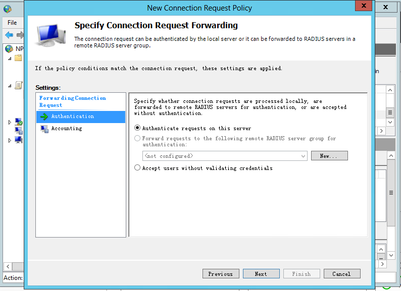
c. Configure the identity authentication location:
# On the Specify Connection Request Forwarding page, select Authentication, and then select Authenticate requests on this server.
# Click Next.
Figure 34 Configuring the identity authentication location
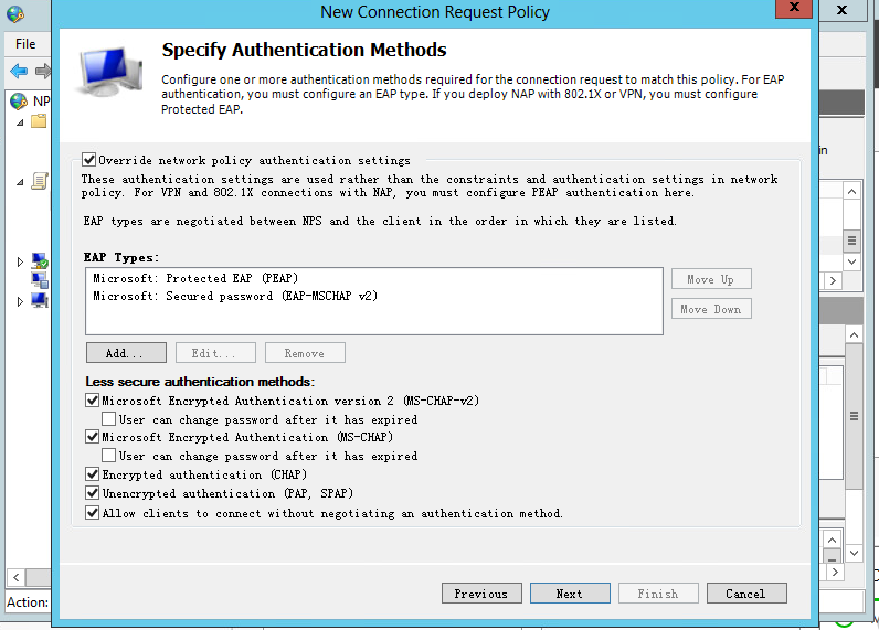
d. Specify authentication methods:
# Select Override network policy authentication settings.
# In the EAP Types box, add Protected EAP (PEAP) and Secured password (EAP-MSCHAP v2).
# In the Less secure authentication methods area, select Microsoft Encrypted Authentication version 2 (MS-CHAP-v2), Microsoft Encrypted Authentication (MS-CHAP), Encrypted authentication (CHAP), Unencrypted authentication (PAP.SPAP), and Allow clients to connect without negotiating an authentication method.
Figure 35 Specifying authentication methods

# Click Next.
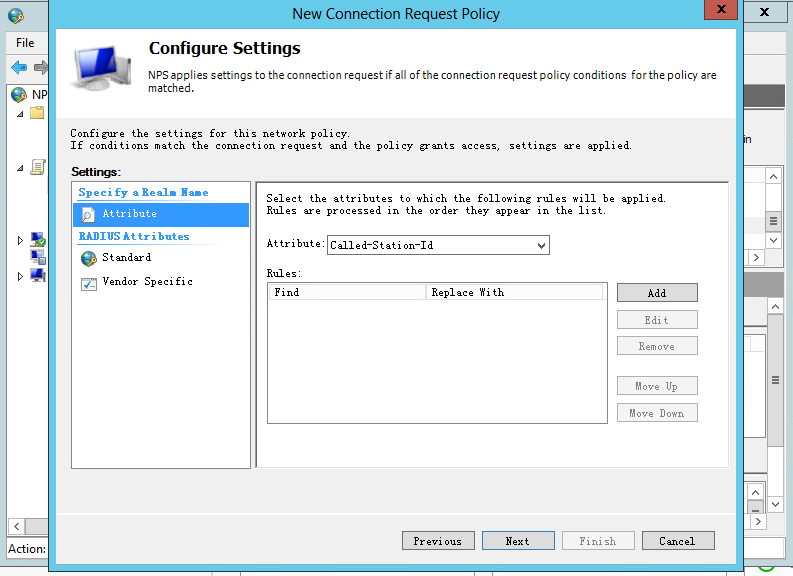
# In the window that opens, click No to open the Configure Settings page.
e. Use the default settings for the policy attribute, and click Next.
Figure 36 Configuring the policy attribute
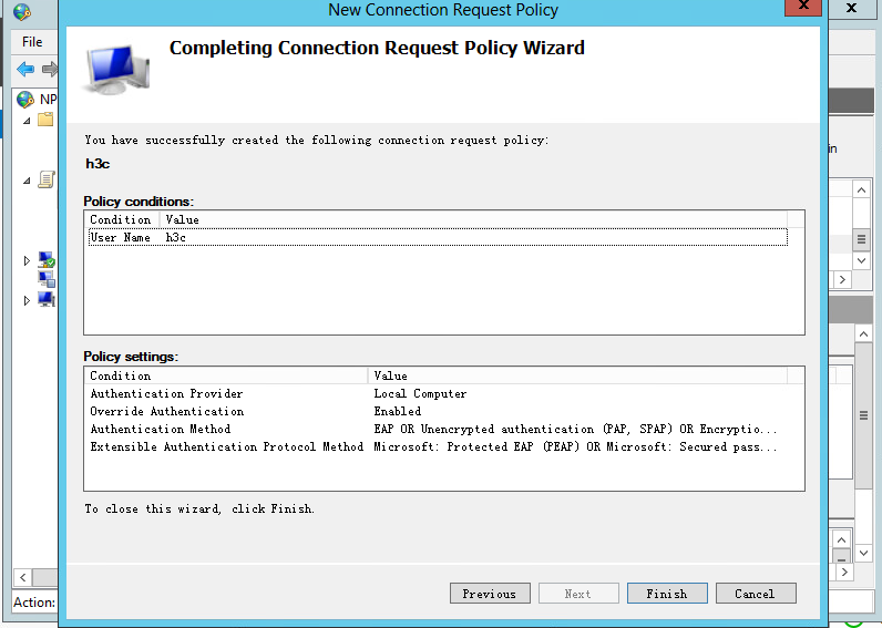
f. Click Finish.
Figure 37 Finishing creating the connection request policy
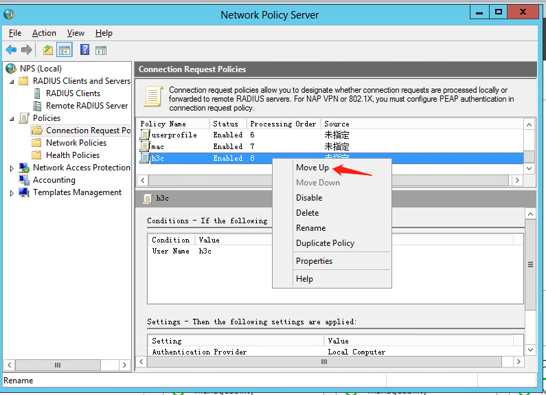
g. Move the connection request policy:
# Select Policies > Connection Request Policies from the left navigation pane of NPS.
# Right-click policy name h3c and select Move Up to move the policy to the first.
Figure 38 Moving the connection request policy to the first

3. Configure a network policy:
a. Add a new network policy:
# Select Policies > Network Policies from the navigation pane.
# Add a network policy.
Figure 39 Creating a network policy
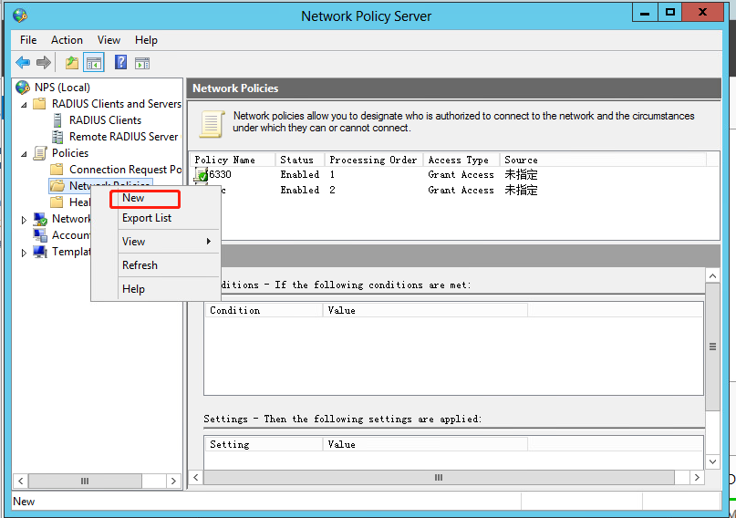
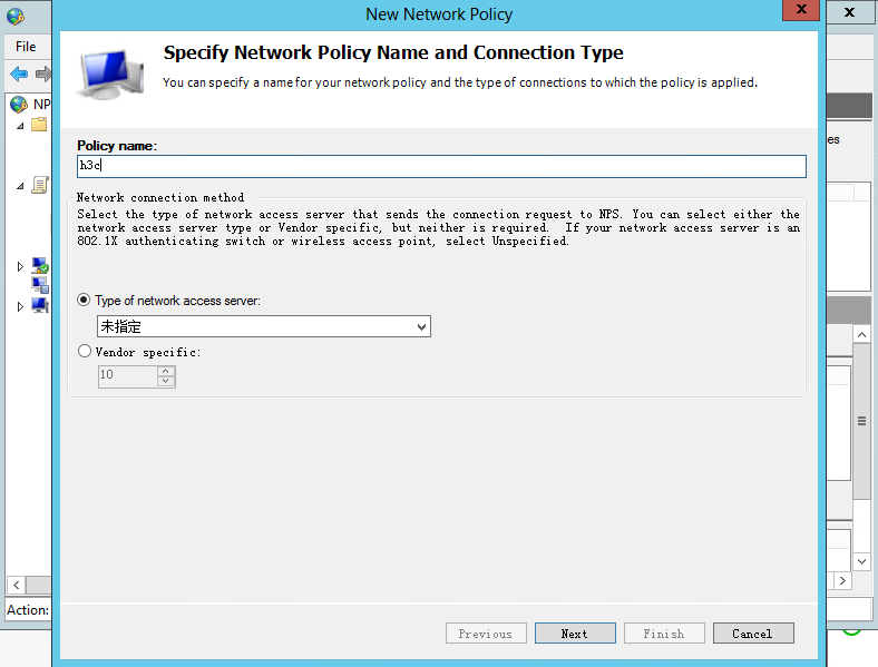
# Set the policy name to h3c, and then click Next.
Figure 40 Configuring the policy name
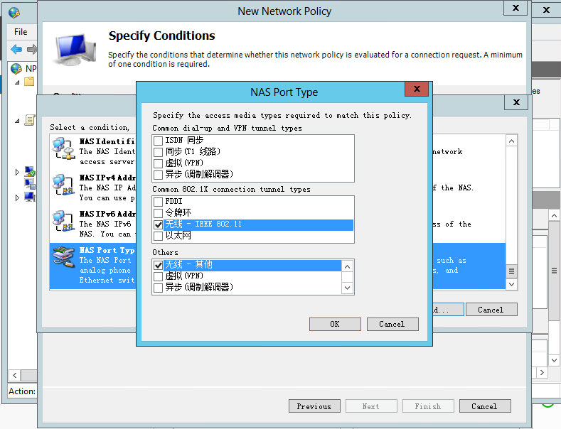
b. Configure the NAS port type:
# In the bottom part of the Specify Conditions page, select NAS Port Type, and then click Add to add the selected types to the network policy.
# In the Common 8021.X connection tunnel types area, select Wireless IEEE – 802.11. In the Others area, select Wireless – Other.
# Click OK.
# Click Next.
Figure 41 Configuring NAS Port Type
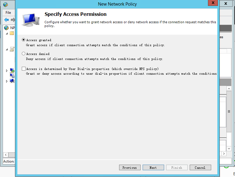
c. On the Specify Access Permission page, select Access granted, and then click Next.
Figure 42 Specifying access permission
d. Specify authentication methods:
# In the EAP Types box, add Protected EAP (PEAP) and Secured password (EAP-MSCHAP v2).
# In the Less secure authentication methods area, select Microsoft Encrypted Authentication version 2 (MS-CHAP-v2), Microsoft Encrypted Authentication (MS-CHAP), Encrypted authentication (CHAP), Unencrypted authentication (PAP.SPAP), and Allow clients to connect without negotiating an authentication method.
Figure 43 Specifying authentication methods
e. On the Configure Constraints and Configure Settings pages, use the default settings, and then click Next.
Figure 44 Configuring constraints
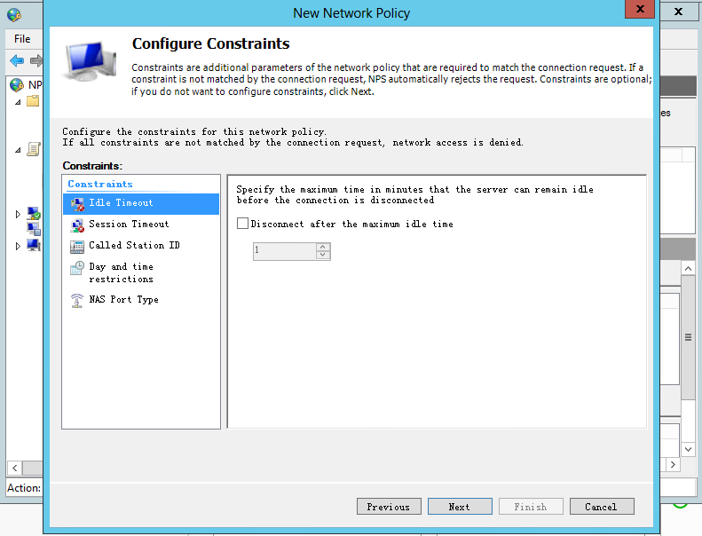
Figure 45 Configuring settings

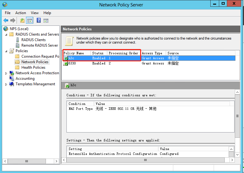
f. Move the network policy:
# Select Policies > Network Policies from the left navigation pane of NPS.
# Right-click policy name h3c and select Move Up to move the policy to the first.
Figure 46 Moving the network policy to the first
Configuring an authorization ACL and authorization VLAN
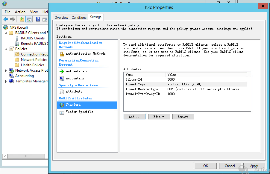
1. Select Policies > Connection Request Policies from the left navigation pane of NPS.
2. Right-click policy name h3c and select Properties.
3. Click the Settings tab.
4. Select Standard for RADIUS Attributes.
5. Add attributes Filter-Id, Tunnel-Type, Tunnel-Pvt-Group-ID, and Tunnel-Medium-Type. The value for the Filter-Id attribute is the number of the authorization ACL and the value for the Tunnel-Pvt-Group-ID attribute is the ID of the authorization VLAN.
Figure 47 Configuring an authorization ACL and authorization VLAN
Verifying the configuration
# On the client, connect to the wireless network. Use username h3c and the correct password to initiate 802.1X authentication and select MSCHAPV2 for phase 2 authentication. Verify that the user can successfully pass the authentication.
# On the AC, verify that the user has come online.
[H3C] display wlan client
Total number of clients: 1
MAC address User name AP name R IP address VLAN
2698-1453-f6ed h3c ap1 1 1.1.1.5 1000
# On the AC, display online 802.1X user information to verify that the server has assigned the authorization ACL and authorization VLAN to the user.
[H3C] display dot1x connection
Total connections: 1
User MAC address : 2698-1453-f6ed
AP name : ap1
Radio ID : 1
SSID : h3c-nps
BSSID : f010-9059-42e9
Username : h3c
Anonymous username : N/A
Authentication domain : nps
IPv4 address : 1.1.1.5
Authentication method : EAP
Initial VLAN : 1
Authorization VLAN : 1000
Authorization ACL number : 3000
Authorization user profile : N/A
Authorization CAR : N/A
Authorization URL : N/A
Authorization IPv6 URL : N/A
Termination action : N/A
Session timeout last from : N/A
Session timeout period : N/A
Online from : 2022/05/12 14:11:18
Online duration : 0h 0m 53s
Configuration files
· AC:
#
radius scheme nps
primary authentication 192.168.106.40 key simple 12345678
primary accounting 192.168.106.40 key simple 12345678
nas-ip 192.168.105.190
#
domain nps
authentication lan-access radius-scheme nps
authorization lan-access radius-scheme nps
accounting lan-access radius-scheme nps
#
dot1x authentication-method eap
#
wlan service-template nps
ssid h3c-nps-dot1x
akm mode dot1x
cipher-suite ccmp
security-ie rsn
client-security authentication-mode dot1x
dot1x domain nps
vlan 1000
client forwarding-location ac
service-template enable
#
wlan ap ap1 model WA6330
serial-id 219801A23V8209E0043Y
radio 1
radio enable
service-template nps
#
acl advanced 3000
rule 0 permit ip
#
vlan 1000
#
interface Vlan-interface 1000
ip address 1.1.1.1 255.255.255.0
#
dhcp server ip-pool 1000
gateway-list 1.1.1.1
network 1.1.1.0 mask 255.255.255.0
dns-list 1.1.1.1
#
· Switch:
#
vlan 1000
#
interface Vlan-interface1000
ip address 1.1.1.2 255.255.255.0
#
interface GigabitEthernet1/0/1
port link-type trunk
port trunk permit vlan 1 1000
#
interface GigabitEthernet1/0/2
port link-type access
Example: Configuring remote MAC authentication using the NPS authentication server
Network configuration
As shown in Figure 49, the AP is connected to the AC over the switch and the client accesses the wireless network through the AP.
Configure MAC authentication to control the client's access to the network resources. Use the NPS server as the RADIUS server and MAC authentication server. The MAC address of the client is used as both the username and password for MAC authentication.
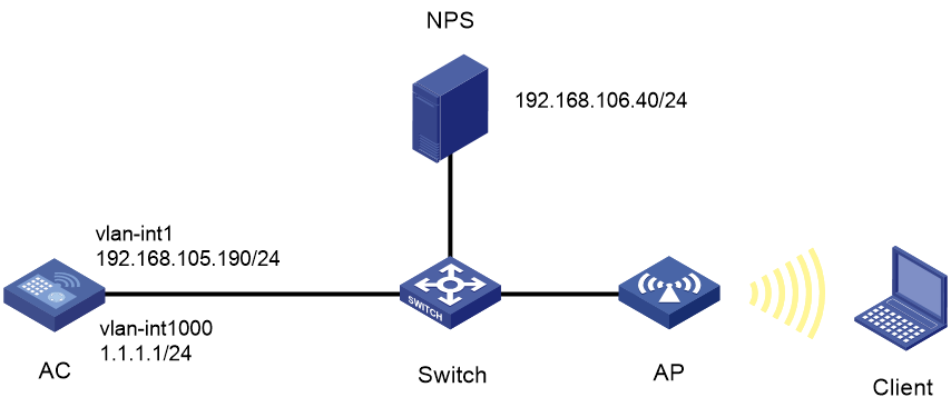
Restrictions and guidelines
Use the serial ID labeled on the AP's rear panel to specify an AP.
Procedures
Configuring the AC
1. Configure an ISP domain:
# Create ISP domain nps.
<H3C> system-view
[H3C] domain nps
# Configure the ISP domain to use RADIUS scheme nps for LAN user authentication, authorization, and accounting.
[H3C-isp-nps] authentication lan-access radius-scheme nps
[H3C-isp-nps] authorization lan-access radius-scheme nps
[H3C-isp-nps] accounting lan-access radius-scheme nps
[H3C-isp-nps] quit
2. Configure a RADIUS scheme:
# Create RADIUS scheme nps.
[H3C] radius scheme nps
# Specify the NPS server as the primary authentication and accounting server and specify a shared key for secure communication with the server. Make sure the shared key is the same as the shared secret configured on the NPS server.
[H3C-radius-nps] primary authentication 192.168.106.40 key simple 12345678
[H3C-radius-nps] primary accounting 192.168.106.40 key simple 12345678
# Specify a NAS-IP for outgoing RADIUS packets.
[H3C-radius-nps] nas-ip 192.168.105.190
3. Configure a service template:
# Create service template nps.
[H3C]wlan service-template nps
# Set the SSID of the service template to h3c-nps-mac.
[H3C-wlan-st-nps] ssid h3c-nps-mac
# Set the AKM mode to preshared key mode.
[H3C-wlan-st-nps] akm mode psk
# Specify the AES-CCMP cipher suite, and enable the RSN IE in beacon and probe responses.
[H3C-wlan-st-nps] cipher-suite ccmp
[H3C-wlan-st-nps] security-ie rsn
# Specify a PSK.
[H3C-wlan-st-nps] preshared-key pass-phrase simple 12345678
# Set the authentication mode to MAC authentication and specify authentication domain nps.
[H3C-wlan-st-nps] client-security authentication-mode mac
[H3C-wlan-st-nps] mac-authentication domain nps
# Assign clients coming online through the service template to VLAN 1000.
[H3C-wlan-st-nps] vlan 1000
# Configure the AC to forward client data traffic. Skip this step if the AC forwards client data traffic by default.
[H3C-wlan-st-nps] client forwarding-location ac
[H3C-wlan-st-nps] service-template enable
4. Bind the service template to radio 1.
[H3C]wlan ap ap1 model WA6330
[H3C-wlan-ap-ap1] serial-id 219801A23V8209E0043Y
[H3C-wlan-ap-ap1] radio 1
[H3C-wlan-ap-ap1] radio enable
[H3C-wlan-ap-ap1] service-template nps
[H3C-wlan-ap-ap1] quit
5. Configure the AC to use the MAC address of the client as both the username and password for MAC authentication. The MAC address is in hexadecimal notation without hyphens and with letters in lower case. (The configuration in this step is the default configuration.)
[H3C] mac-authentication user-name-format mac-address without-hyphen lowercase
Configure ACL 3000. (Configure the ACL as needed.)
[H3C] acl advanced 3000
[H3C-acl-ipv4-adv-3000] rule 0 permit ip
6. Configure interfaces on the AC:
# Create VLAN 1000 and VLAN-interface VLAN 1000, and assign an IP address and mask to the VLAN interface.
[H3C] vlan 1000
[H3C-vlan1000] quit
[H3C] interface vlan-interface 1000
[H3C-Vlan-interface1000] ip address 1.1.1.1 255.255.255.0
[H3C-Vlan-interface1000] quit
# Enable the DHCP service.
[H3C] dhcp enable
# Create a DHCP address pool named 1000.
[H3C] dhcp server ip-pool 1000
[H3C-dhcp-pool-1000] quit
# Specify primary subnet 1.1.1.0/24 for dynamic allocation in the DHCP address pool.
[H3C-dhcp-pool-1000] network 1.1.1.0 mask 255.255.255.0
# Specify gateway address 1.1.1.1.
[H3C-dhcp-pool-1000] gateway-list 1.1.1.1
# Specify DNS server address 1.1.1.1 in the DHCP address pool.
[H3C-dhcp-pool-1000] dns-list 1.1.1.1
[H3C-dhcp-pool-1000] quit
# Create VLAN-interface 1 and assign an IP address to the VLAN interface.
[H3C] interface vlan-interface 1
[H3C-Vlan-interface1] ip address 192.168.105.190 255.255.255.0
[H3C-Vlan-interface1] quit
# Set the link type of GigabitEthernet 1/0/1 (the interface connected to the switch) to trunk, and assign the interface to VLAN 1 and VLAN 1000.
[H3C] interface gigabitethernet 1/0/1
[H3C-GigabitEthernet1/0/1] port link-type trunk
[H3C-GigabitEthernet1/0/1] port trunk permit vlan 1 1000
[H3C-GigabitEthernet1/0/1] quit
Configuring the switch
# Create VLAN 1000 for forwarding client wireless packets.
[Switch] vlan 1000
[Switch-vlan1000] quit
# Create VLAN-interface 1000 and assign an IP address to the interface.
[Switch] interface vlan-interface 1000
[Switch-Vlan-interface1000] ip address 1.1.1.2 255.255.255.0
[Switch-Vlan-interface1000] quit
# Set the link type of GigabitEthernet 1/0/1 (the interface connected to the AC) to trunk, and assign the interface to VLAN 1 and VLAN 1000.
[Switch] interface gigabitethernet 1/0/1
[Switch-GigabitEthernet1/0/1] port link-type trunk
[Switch-GigabitEthernet1/0/1] port trunk permit vlan 1 1000
[Switch-GigabitEthernet1/0/1] quit
# Set the link type of GigabitEthernet 1/0/2 (the interface connected to the AP) to access.
[Switch] interface gigabitethernet 1/0/2
[Switch-GigabitEthernet1/0/2] port link-type access
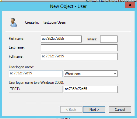
Adding a user account on the NPS server
1. On the NPS server, select Start > Control Panel > Administrative Tools, and then double-click Active Directory Users and Computers.
The Active Directory Users and Computers window is displayed.
Figure 49 Active Directory Users and Computers window

2. From the navigation pane, click Users under the test.com node.
Figure 50 Users window

3. Right-click Users, and select New > User from the shortcut menu to display the dialog box for adding a user.
Figure 51 Users options

4. In the dialog box, set the first name, full name, and user logon name to ac7352c72d55 (MAC address of the client), and then click Next.
Figure 52 Entering the first name, full name, and user logon name
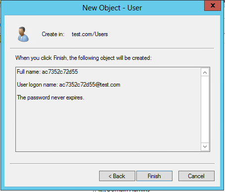
5. In the dialog box that opens, configure and confirm the password of the user, select options as needed, and click Next.
Figure 53 Setting the user's password
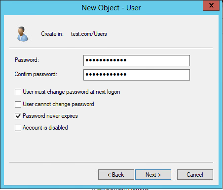
Figure 54 Finishing creating the user
6. From the navigation pane, click Users under the test.com node. In the right pane, right-click user ac7352c72d55 and select Properties.
Figure 55 Selecting the Properties option for the user
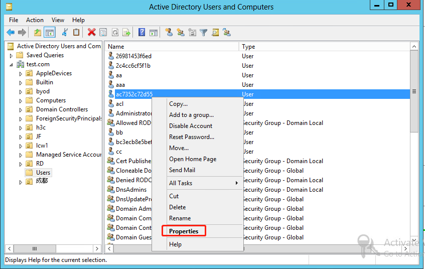
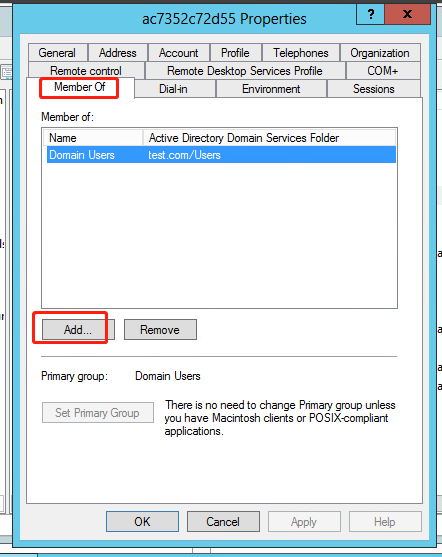
7. In the dialog box that opens, click the Member Of tab, select the Domain Users primary group, and then click Add.
Figure 56 Adding a primary group
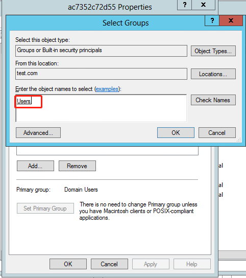
8. In the Select Groups dialog box, enter Users in the Enter the object names to select field, and click OK.
User ac7352c72d55 is added to group Users.
Figure 57 Adding user ac7352c72d55 to group Users
Configuring the NPS server (RADIUS server)
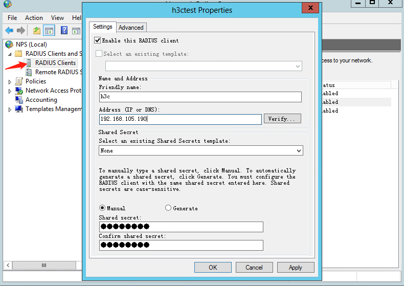
1. Configure the RADIUS client:
a. Open the Network Policy Server (NPS) component. In the left navigation pane, select RADIUS Client and Servers > RADIUS Clients.
b. Add a new RADIUS client: Enter the IP address of the AC in the Address (IP or DNS) field, which is 192.168.105.190. Enter the shared secret, which must be the same as the shared key configured for the primary authentication and accounting server. In this example, the shared secret is 12345678.
Figure 58 Creating a RADIUS client
2. Configure a connection request policy:
a. Add a new connection request policy:
# Select Policies > Connection Request Policies from the navigation pane.
# Right-click Connection Request Policies and create a request policy.
# Configure the policy name as h3c, use the default settings for other options, and then click Next.
Figure 59 Creating a connection request policy

Figure 60 Configuring the policy name

b. Configure the NAS port type:
# In the bottom part of the Specify Conditions page, select NAS Port Type, and then click Add to add the selected types to the connection request policy.
# In the Common 8021.X connection tunnel types area, select Wireless IEEE – 802.11. In the Others area, select Wireless – Other.
# Click OK.
Figure 61 Configuring NAS Port Type

# Click Next to open the Specify Connection Request Forwarding page.
c. Configure the identity authentication location:
# On the Specify Connection Request Forwarding page, select Authentication, and then select Authenticate requests on this server.
# Click Next.
Figure 62 Configuring the identity authentication location

d. Specify authentication methods:
# Select Override network policy authentication settings.
# In the EAP Types box, add Protected EAP (PEAP) and Secured password (EAP-MSCHAP v2).
# In the Less secure authentication methods area, select Microsoft Encrypted Authentication version 2 (MS-CHAP-v2), Microsoft Encrypted Authentication (MS-CHAP), Encrypted authentication (CHAP), Unencrypted authentication (PAP.SPAP), and Allow clients to connect without negotiating an authentication method.
Figure 63 Specifying authentication methods
# Click Next.
# In the window that opens, click No to open the Configure Settings page.
e. Use the default settings for the policy attribute, and click Next.
Figure 64 Configuring the policy attribute

f. Click Finish.
Figure 65 Finishing creating the connection request policy

g. Move the connection request policy:
# Select Policies > Connection Request Policies from the left navigation pane of NPS.
# Right-click policy name h3c and select Move Up to move the policy to the first.
Figure 66 Moving the connection request policy to the first
3. Configure a network policy:
a. Add a new network policy:
# Select Policies > Network Policies from the navigation pane.
# Add a network policy.
Figure 67 Creating a network policy

# Set the policy name to h3c, and then click Next.
Figure 68 Configuring the policy name

b. Configure the NAS port type:
# In the bottom part of the Specify Conditions page, select NAS Port Type, and then click Add to add the selected types to the network policy.
# In the Common 8021.X connection tunnel types area, select Wireless IEEE – 802.11. In the Others area, select Wireless – Other.
# Click OK.
# Click Next.
Figure 69 Configuring NAS Port Type

c. On the Specify Access Permission page, select Access granted, and then click Next.
Figure 70 Specifying access permission

d. Specify authentication methods:
# In the EAP Types box, add Protected EAP (PEAP) and Secured password (EAP-MSCHAP v2).
# In the Less secure authentication methods area, select Microsoft Encrypted Authentication version 2 (MS-CHAP-v2), Microsoft Encrypted Authentication (MS-CHAP), Encrypted authentication (CHAP), Unencrypted authentication (PAP.SPAP), and Allow clients to connect without negotiating an authentication method.
Figure 71 Specifying authentication methods

# Click Next.
# In the window that opens, click No.
e. On the Configure Constraints and Configure Settings pages, use the default settings, and then click Next.
Figure 72 Configuring constraints

Figure 73 Configuring settings
# Click Finish.
f. Move the network policy:
# Select Policies > Network Policies from the left navigation pane of NPS.
# Right-click policy name h3c and select Move Up to move the policy to the first.
Figure 74 Moving the network policy to the first

Configuring an authorization ACL and authorization VLAN
1. Select Policies > Connection Request Policies from the left navigation pane of NPS.
2. Right-click policy name h3c and select Properties.
3. Click the Settings tab.
4. Select Standard for RADIUS Attributes.
5. Add attributes Filter-Id, Tunnel-Type, Tunnel-Pvt-Group-ID, and Tunnel-Medium-Type. The value for the Filter-Id attribute is the number of the authorization ACL and the value for the Tunnel-Pvt-Group-ID attribute is the ID of the authorization VLAN.
Figure 75 Configuring an authorization ACL and authorization VLAN

Verifying the configuration
# On the client with MAC address ac73-52c7-2d55, connect to wireless network h3c-nps-mac. Enter password ac73-52c7-2d55. Verify that the user can successfully pass the authentication.
# On the AC, verify that the user has come online.
[H3C] display wlan client
Total number of clients: 1
MAC address User name AP name R IP address VLAN
ac73-52c7-2d55 ac7352c72d55 ap1 1 1.1.1.5 1000
# On the AC, display online MAC authentication user information to verify that the server has assigned the authorization ACL and authorization VLAN to the user.
[H3C] display mac-authentication connection
Total connections: 1
User MAC address : ac73-52c7-2d55
AP name : ap1
Radio ID : 1
SSID : h3c-nps-mac
BSSID : f010-9059-42ea
Username : ac7352c72d55
Authentication domain : nps
Authentication method : PAP
Initial VLAN : 1
Authorization VLAN : 1000
Authorization ACL number : 3000
Authorization user profile : N/A
Authorization CAR : N/A
Authorization URL : N/A
Authorization IPv6 URL : N/A
Authorization Microsegment ID : N/A
Termination action : N/A
Session timeout last from : N/A
Session timeout period : N/A
Online from : 2022/05/12 15:05:21
Online duration : 0h 4m 15s
Configuration files
· AC:
#
radius scheme nps
primary authentication 192.168.106.40 key simple 12345678
primary accounting 192.168.106.40 key simple 12345678
nas-ip 192.168.105.190
#
domain nps
authentication lan-access radius-scheme nps
authorization lan-access radius-scheme nps
accounting lan-access radius-scheme nps
#
mac-authentication user-name-format mac-address without-hyphen lowercase
#
wlan service-template nps
ssid h3c-nps-mac
akm mode psk
cipher-suite ccmp
security-ie rsn
preshared-key pass-phrase simple 12345678
client-security authentication-mode mac
mac-authentication domain nps
vlan 1000
client forwarding-location ac
service-template enable
#
wlan ap ap1 model WA6330
serial-id 219801A23V8209E0043Y
radio 1
radio enable
service-template nps
#
acl advanced 3000
rule 0 permit ip
#
vlan 1000
#
interface Vlan-interface 1000
ip address 1.1.1.1 255.255.255.0
#
dhcp server ip-pool 1000
gateway-list 1.1.1.1
network 1.1.1.0 mask 255.255.255.0
dns-list 1.1.1.1
#
· Switch:
#
vlan 1000
#
interface Vlan-interface1000
ip address 1.1.1.2 255.255.255.0
#
interface GigabitEthernet1/0/1
port link-type trunk
port trunk permit vlan 1 1000
#
interface GigabitEthernet1/0/2
port link-type access
