- Table of Contents
- Related Documents
-
| Title | Size | Download |
|---|---|---|
| 02-Cisco ISE Server Configuration Examples | 3.50 MB |
|
|
|
H3C Access Controllers |
|
Access Authentication by Cisco ISE Server |
|
Configuration Examples |
|
|
Copyright © 2023 New H3C Technologies Co., Ltd. All rights reserved.
No part of this manual may be reproduced or transmitted in any form or by any means without prior written consent of New H3C Technologies Co., Ltd.
Except for the trademarks of New H3C Technologies Co., Ltd., any trademarks that may be mentioned in this document are the property of their respective owners.
The information in this document is subject to change without notice.
Example: Configuring Cisco ISE-based 802.1X PEAP authentication
Example: Configuring Cisco ISE-based MAC authentication
Example: Configuring Cisco ISE-based portal authentication
Example: Configuring Cisco ISE-based HWTACACS authentication for SSH login
Introduction
The following information provides examples for configuring H3C access controllers to use a Cisco ISE server to authenticate wireless clients. The examples include configuring Cisco ISE-based 802.1X authentication, MAC authentication, portal authentication, and SSH login HWTACACS authentication.
Software versions used
The following configuration examples were created and verified on the following hardware and software versions:
· Cisco ISE server running 2.3.0.298.
· H3C access controller running R5428 or later.
Example: Configuring Cisco ISE-based 802.1X PEAP authentication
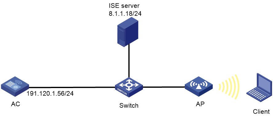
Network configuration
As shown in Figure 1, the AP is connected to the AC over the switch and the client accesses the wireless network through the AP.
Configure the devices and server to meet the following requirements:
· The client must pass 802.1X PEAP authentication to access the wireless network.
· The ISE server assigns an authorization ACL and an authorization VLAN to the client after the client passes 802.1X PEAP authentication.

Procedures
|
|
IMPORTANT: This configuration example only covers the major settings related to authenticating the client by 802.1X authentication on the Cisco ISE server. For information about the network connectivity settings, see the manuals for the devices and server. Make sure the devices and server have network connectivity. |
Configuring the AC
1. Configure the AC to use EAP relay to authenticate the 802.1X client.
<AC> system-view
[AC] dot1x authentication-method eap
2. Configure a RADIUS scheme:
# Create RADIUS scheme ise.
[AC] radius scheme ise
# Specify the ISE server at 8.1.1.18 as the primary authentication server and specify a shared key for secure communication with the server. Make sure the shared key is the same as the shared secret configured on the ISE server.
[AC-radius-ise] primary authentication 8.1.1.18 key cipher $c$3$FpBySjKd6TF17QmPAQ83vNM+mNuZHUw=
# Exclude the domain name from usernames sent to the ISE server.
[AC-radius-ise] user-name-format without-domain
# Specify 191.120.1.56 as the NAS IP address of RADIUS packets sent to the ISE server. Make sure the NAS IP address is the same as that specified on the ISE server for the AC.
[AC-radius-ise] nas-ip 191.120.1.56
[AC-radius-ise] quit
3. Configure an ISP domain:
# Create ISP domain ise.
[AC] domain ise
# Configure the ISP domain to use RADIUS scheme ise for LAN user authentication and authorization.
[AC-isp-ise] authentication lan-access radius-scheme ise
[AC-isp-ise] authorization lan-access radius-scheme ise
[AC-isp-ise] quit
4. Configure a service template:
# Create service template ise.
[AC] wlan service-template ise
# Set the SSID of the service template to 000AAA-MACAU.
[AC-wlan-st-ise] ssid 000AAA-MACAU
# Assign clients coming online through the service template to VLAN 71.
[AC-wlan-st-ise] vlan 71
# Set the AKM mode to 802.1X.
[AC-wlan-st-ise] akm mode dot1x
# Specify the AES-CCMP cipher suite, and enable the RSN IE in beacon and probe responses.
[AC-wlan-st-ise] cipher-suite ccmp
[AC-wlan-st-ise] security-ie rsn
# Set the authentication mode to 802.1X authentication and specify authentication domain ise.
[AC-wlan-st-ise] client-security authentication-mode dot1x
[AC-wlan-st-ise] dot1x domain ise
# Enable the service template.
[AC-wlan-st-ise] service-template enable
[AC-wlan-st-ise] quit
5. Configure a manual AP:
# Configure an AP named ax and specify its model and serial ID.
[AC] wlan ap ax model WA6528
[AC-wlan-ap-ax] serial-id 219801A1LH8188E00011
# Enable radio 1 and bind service template ise to the radio.
[AC-wlan-ap-ax] radio 1
[AC-wlan-ap-ax-radio-1] radio enable
[AC-wlan-ap-ax-radio-1] service-template ise
[AC-wlan-ap-ax-radio-1] quit
[AC-wlan-ap-ax] quit
6. Configure advanced ACL 3100 and a rule to deny the client from accessing 8.1.1.5.
[AC] acl advanced 3100
[AC-acl-ipv4-adv-3100] rule 1 deny ip destination 8.1.1.5 0
[AC-acl-ipv4-adv-3100] quit
7. Configure authorization VLAN settings:
# Create VLAN 4094 and VLAN-interface 4094, and assign an IP address to the VLAN interface.
[AC] vlan 4094
[AC-vlan4094] quit
[AC] interface vlan-interface 4094
[AC-Vlan-interface4094] ip address 191.94.0.1 24
[AC-Vlan-interface4094] quit
# Configure DHCP address pool vlan4094 for VLAN 4094.
[AC] dhcp server ip-pool vlan4094
[AC-dhcp-pool-vlan4094] network 191.94.0.0 mask 255.255.255.0
[AC-dhcp-pool-vlan4094] gateway-list 191.94.0.1
[AC-dhcp-pool-vlan4094] dns-list 191.94.0.1
[AC-dhcp-pool-vlan4094] quit
Configuring the ISE server
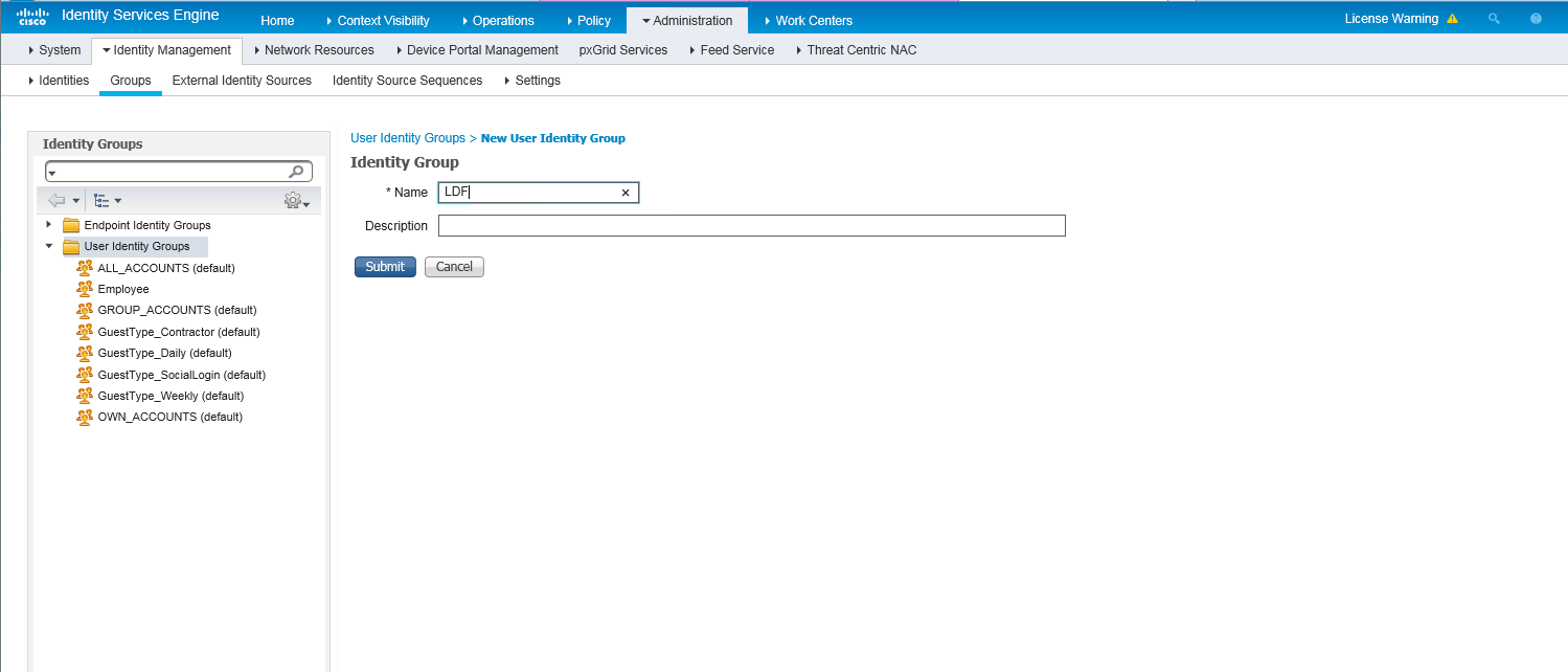
1. Create a user group:
a. On the top navigation bar, select Administration > Identity Management > Groups.
b. From the left navigation pane, select User Identity Groups.
c. Click Add.
d. On the page that opens, set the name to LDF.
e. Click Submit.
Figure 2 Creating a user group

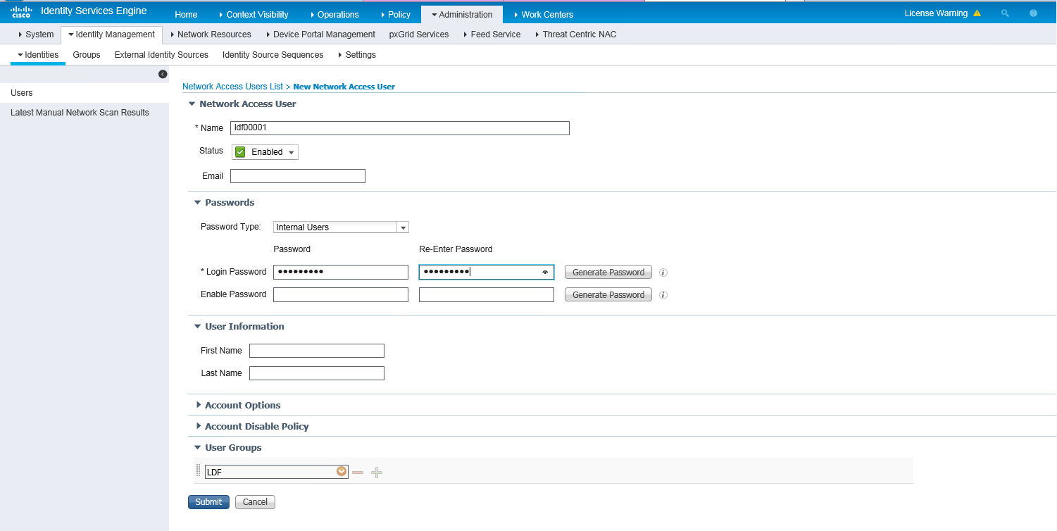
2. Create a network access user:
a. On the top navigation bar, select Administration > Identity Management > Identities.
b. From the left navigation pane, select Users.
c. Click Add.
d. On the page that opens, set the name to ldf00001 and password to Ldf123456, and bind the user to user group LDF.
Make sure the password contains uppercase letters, lowercase letters, and digits.
e. Click Submit.
Figure 3 Creating a network access user

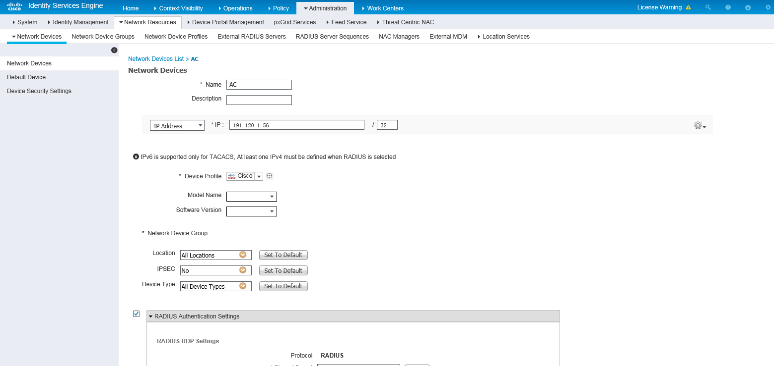
3. Add the AC to the server as a network access device:
a. On the top navigation bar, select Administration > Network Resources > Network Devices.
b. Click Add.
c. Set the name to AC, specify IP address 191.120.1.56, select RADIUS Authentication Settings, and set the shared secret to H3cc.
Make sure the IP address is the same as the NAS IP address of RADIUS packets on the AC.
Make sure the shared secret is the same as the shared key configured on the AC.
d. Save the configuration.
Figure 4 Adding the AC to the server
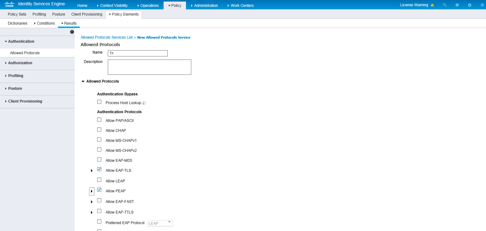
4. Configure authentication protocols:
a. On the top navigation bar, select Policy > Policy Elements > Results.
b. From the left navigation pane, select Authentication > Allowed Protocols.
c. Create an allowed protocols service named 1x, and select Allow EAP-TLS and Allow PEAP.
d. Save the configuration.
Figure 5 Creating an allowed protocols service
5. Configuring an authorization ACL:
a. On the top navigation bar, select Policy > Policy Elements > Results.
b. From the left navigation pane, select Authorization > Authorization Profiles.
c. Click Add.
d. In the Authorization Profile area, set the name to acl_3100 and select Cisco from the Network Device Profile field. In the Advanced Attributes Settings area, select attribute Radius:Filter-ID and set the attribute value to 3100 (an ACL number).
e. Save the configuration.
Figure 6 Configuring an authorization ACL

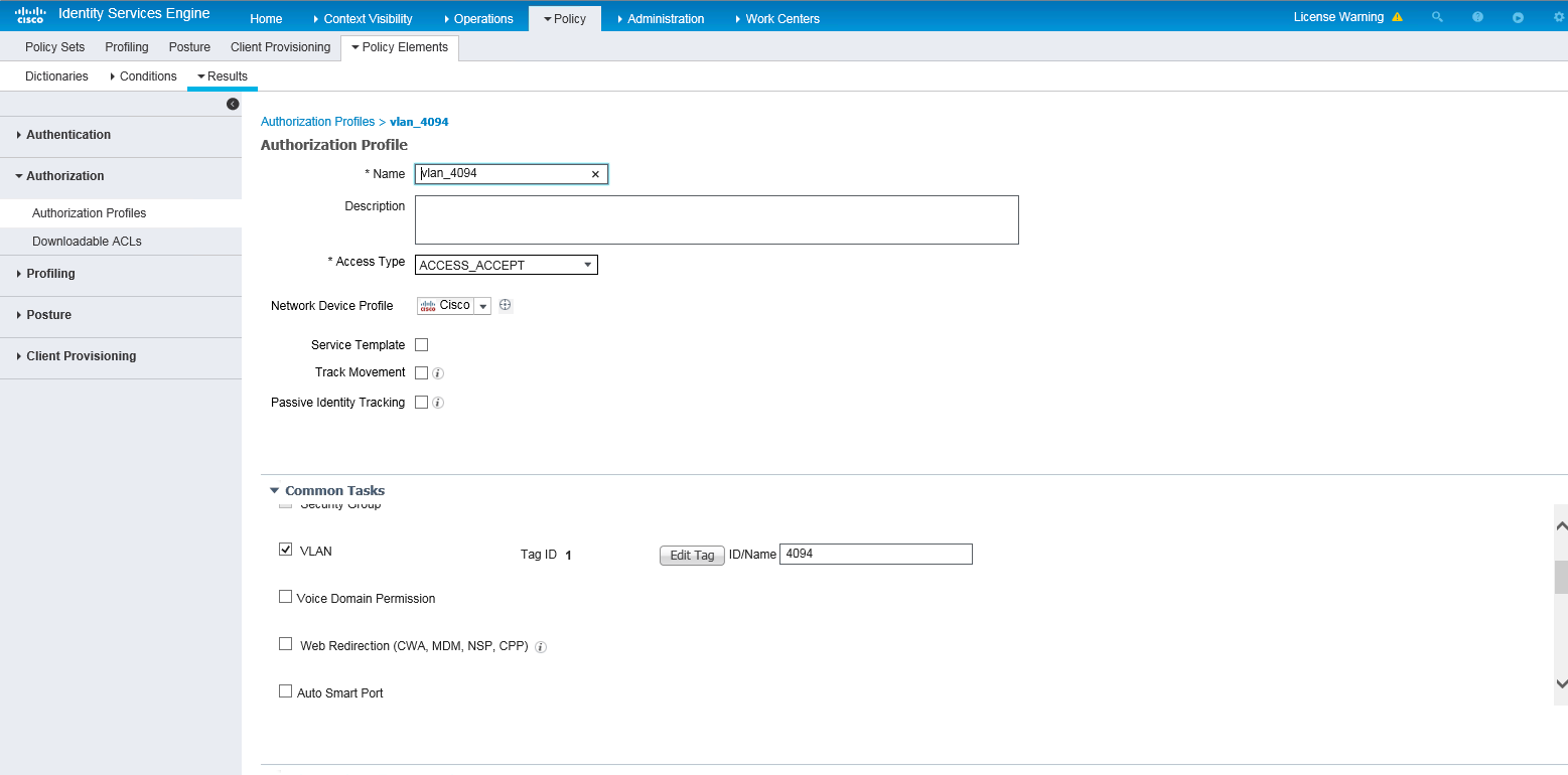
6. Configuring an authorization VLAN:
a. On the top navigation bar, select Policy > Policy Elements > Results.
b. From the left navigation pane, select Authorization > Authorization Profiles.
c. Click Add.
d. In the Authorization Profile area, set the name to vlan_4094 and select Cisco from the Network Device Profile field. In the Custom Tasks area, select the VLAN option and enter 4094 in the ID/Name field.
e. Save the configuration.
Figure 7 Configuring an authorization VLAN
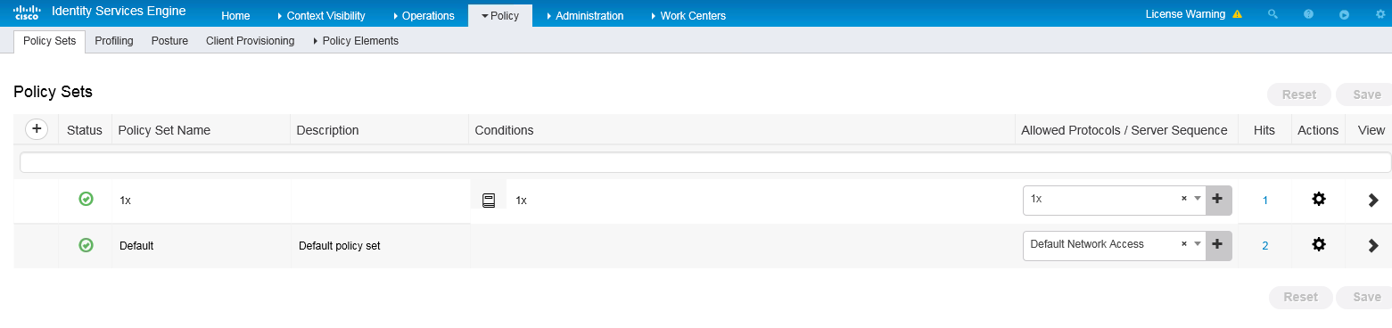
7. Configure an authentication and authorization policy set:
a. On the top navigation bar, select Policy > Policy Sets.
b. Click the plus icon + under Policy Sets.
c. Set the policy set name to 1x. Set the conditions name to 1x, select Wired_Dot1x or Wireless Dot1x as the conditions, and select 1x from the Allowed Protocols/Server Sequence list.
Figure 8 Configuring an authentication and authorization policy set
d. Click the icon in the View column for the authentication and authorization policy set.
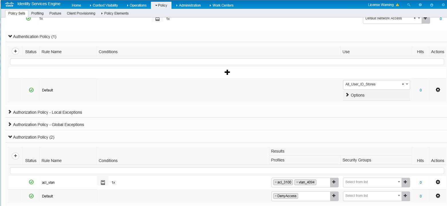
e. In the Authorization Policy area, add an authorization policy named acl_vlan. In the Results > Profiles column for the authorization policy, select profiles acl_3100 and vlan_4094.
Figure 9 Configuring an authorization policy
f. Save the configuration.
Verifying the configuration
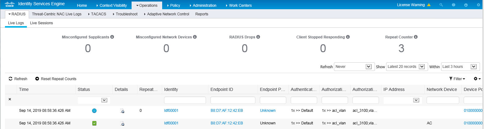
1. On the top navigation bar, select Operations > RADIUS > Live Logs. View live log information for online clients.
Figure 10 Viewing live log information for online clients
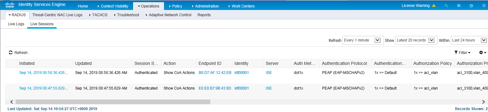
2. On the top navigation bar, select Operations > RADIUS > Live Sessions. View live session information for online clients.
Figure 11 Viewing live session information for online clients
Configuration files
#
vlan 4094
#
dhcp server ip-pool vlan4094
network 191.94.0.0 mask 255.255.255.0
gateway-list 191.94.0.1
dns-list 191.94.0.1
#
interface vlan-interface 4094
ip address 191.94.0.1 24
#
acl advanced 3100
rule 1 deny ip destination 8.1.1.5 0
#
radius scheme ise
primary authentication 8.1.1.19 key cipher $c$3$FpBySjKd6TF17QmPAQ83vNM+mNuZHUw=
user-name-format without-domain
nas-ip 191.120.1.56
#
domain ise
authentication lan-access radius-scheme ise
authorization lan-access radius-scheme ise
#
wlan service-template ise
ssid 000AAA-MACAU
vlan 71
akm mode dot1x
cipher-suite ccmp
security-ie rsn
client-security authentication-mode dot1x
dot1x domain ise
service-template enable
#
wlan ap ax model WA6528
serial-id 219801A1LH8188E00011
radio 1
radio enable
service-template ise
#
dot1x authentication-method eap
Example: Configuring Cisco ISE-based MAC authentication
Network configuration
As shown in Figure 12, the AP is connected to the AC over the switch and the client accesses the wireless network through the AP.
To control the client's access to the network resources, configure the devices and server to meet the following requirements:
· The client must pass MAC authentication to access the wireless network.
· The client and AP use the PSK AKM mode to secure data packets between them.
· The ISE server assigns an authorization ACL and an authorization VLAN to the client after the client passes MAC authentication.
Procedures
|
|
IMPORTANT: This configuration example only covers the major settings related to authenticating the client by MAC authentication on the Cisco ISE server. For information about the network connectivity settings, see the manuals for the devices and server. Make sure the devices and server have network connectivity. |
Configuring the AC
1. Configure a RADIUS scheme:
# Create RADIUS scheme ise.
<AC> system-view
[AC] radius scheme ise
# Specify the ISE server at 8.1.1.18 as the primary authentication server and specify a shared key for secure communication with the server. Make sure the shared key is the same as the shared secret configured on the ISE server.
[AC-radius-ise] primary authentication 8.1.1.18 key cipher $c$3$FpBySjKd6TF17QmPAQ83vNM+mNuZHUw=
# Exclude the domain name from usernames sent to the ISE server.
[AC-radius-ise] user-name-format without-domain
# Specify 191.120.1.56 as the NAS IP address of RADIUS packets sent to the ISE server. Make sure the NAS IP address is the same as that specified on the ISE server for the AC.
[AC-radius-ise] nas-ip 191.120.1.56
[AC-radius-ise] quit
2. Configure an ISP domain:
# Create ISP domain ise.
[AC] domain ise
# Configure the ISP domain to use RADIUS scheme ise as the default methods for user authentication and authorization.
[AC-isp-ise] authentication default radius-scheme ise
[AC-isp-ise] authorization default radius-scheme ise
[AC-isp-ise] quit
3. Configure a service template:
# Create service template isemac2.
[AC] wlan service-template isemac2
# Specify an SSID for the service template.
[AC-wlan-st-isemac2] ssid 000AAAMACAU-MAC-CCMP-WPA
# Assign clients coming online through the service template to VLAN 71.
[AC-wlan-st-isemac2] vlan 71
# Set the PSK AKM mode and specify a PSK.
[AC-wlan-st-isemac2] akm mode psk
[AC-wlan-st-isemac2] preshared-key pass-phrase cipher $c$3$XYqokG6I8YoOymukIyvxoJuzFoB+oVJD6exoqw==
# Specify the AES-CCMP cipher suite, and enable the RSN IE in beacon and probe responses.
[AC-wlan-st-isemac2] cipher-suite ccmp
[AC-wlan-st-isemac2] security-ie rsn
# Set the access authentication mode to MAC authentication and specify authentication domain ise.
[AC-wlan-st-isemac2] client-security authentication-mode mac
[AC-wlan-st-isemac2] mac-authentication domain ise
# Enable the service template.
[AC-wlan-st-isemac2] service-template enable
[AC-wlan-st-isemac2] quit
4. Configure a manual AP:
# Configure an AP named ax and specify its model and serial ID.
[AC] wlan ap ax model WA6528
[AC-wlan-ap-ax] serial-id 219801A1LH8188E00011
# Specify VLAN 1 for the AP.
[AC-wlan-ap-ax] vlan 1
# Enable radio 1 and bind service template isemac2 to the radio.
[AC-wlan-ap-ax] radio 1
[AC-wlan-ap-ax-radio-1] radio enable
[AC-wlan-ap-ax-radio-1] service-template isemac2
[AC-wlan-ap-ax-radio-1] quit
[AC-wlan-ap-ax] quit
5. Configure advanced ACL 3100 and a rule to deny the client from accessing 8.1.1.5.
[AC] acl advanced 3100
[AC-acl-ipv4-adv-3100] rule 1 deny ip destination 8.1.1.5 0
[AC-acl-ipv4-adv-3100] quit
6. Configure authorization VLAN settings:
# Create VLAN 4094 and VLAN-interface 4094, and assign an IP address to the VLAN interface.
[AC] vlan 4094
[AC-vlan4094] quit
[AC] interface vlan-interface 4094
[AC-Vlan-interface4094] ip address 191.94.0.1 24
[AC-Vlan-interface4094] quit
# Configure DHCP address pool vlan4094 for VLAN 4094.
[AC] dhcp server ip-pool vlan4094
[AC-dhcp-pool-vlan4094] network 191.94.0.0 mask 255.255.255.0
[AC-dhcp-pool-vlan4094] gateway-list 191.94.0.1
[AC-dhcp-pool-vlan4094] dns-list 191.94.0.1
[AC-dhcp-pool-vlan4094] quit
Configuring the ISE server
1. Create a user group:
a. On the top navigation bar, select Administration > Identity Management > Groups.
b. From the left navigation pane, select User Identity Groups.
c. Click Add.
d. On the page that opens, set the name to LDF.
e. Click Submit.
Figure 13 Creating a user group
2. Create a network access user:
a. On the top navigation bar, select Administration > Identity Management > Identities.
b. From the left navigation pane, select Users.
c. Click Add.
d. On the page that opens, set the name to ldf00001 and password to Ldf123456, and bind the user to user group LDF.
Make sure the password contains uppercase letters, lowercase letters, and digits.
e. Click Submit.
Figure 14 Creating a network access user
3. Add the AC to the server as a network access device:
a. On the top navigation bar, select Administration > Network Resources > Network Devices.
b. Click Add.
c. On the page that opens, set the name to AC, specify IP address 191.120.1.56, select RADIUS Authentication Settings, and set the shared secret to H3cc.
Make sure the IP address is the same as the NAS IP address of RADIUS packets on the AC.
Make sure the shared secret is the same as the shared key configured on the AC.
d. Save the configuration.
Figure 15 Adding the AC to the server

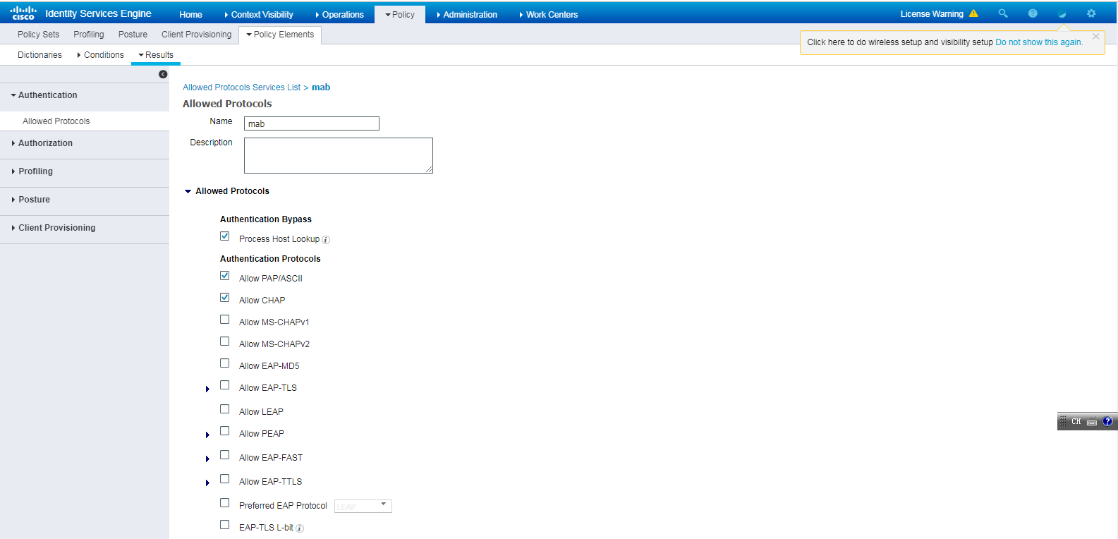
4. Configure authentication protocols:
a. On the top navigation bar, select Policy > Policy Elements > Results.
b. From the left navigation pane, select Authentication > Allowed Protocols.
c. Create an allowed protocols service named mab. In the Authentication Bypass area, select Process Host Lookup. In the Authentication Protocols area, select Allow PAP/ASCII and Allow CHAP.
d. Save the configuration.
Figure 16 Configuring authentication protocols
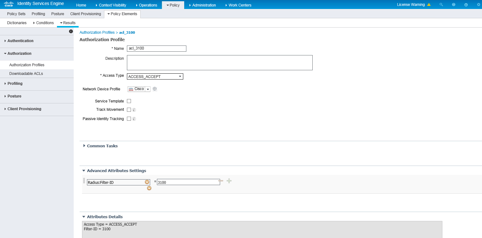
5. Configuring an authorization ACL:
a. On the top navigation bar, select Policy > Policy Elements > Results.
b. From the left navigation pane, select Authorization > Authorization Profiles.
c. Click Add.
d. In the Authorization Profile area, set the name to acl_3100 and select Cisco from the Network Device Profile field. In the Advanced Attributes Settings area, select attribute Radius:Filter-ID and set the attribute value to 3100 (an ACL number).
e. Save the configuration.
Figure 17 Configuring an authorization ACL
6. Configuring an authorization VLAN:
a. On the top navigation bar, select Policy > Policy Elements > Results.
b. From the left navigation pane, select Authorization > Authorization Profiles.
c. Click Add.
d. In the Authorization Profile area, set the name to vlan_4094 and select Cisco from the Network Device Profile field. In the Custom Tasks area, select the VLAN option and enter 4094 in the ID/Name field.
e. Save the configuration.
Figure 18 Configuring an authorization VLAN

7. Configure an authentication and authorization policy set:
a. On the top navigation bar, select Policy > Policy Sets.
b. Click the plus icon + under Policy Sets.
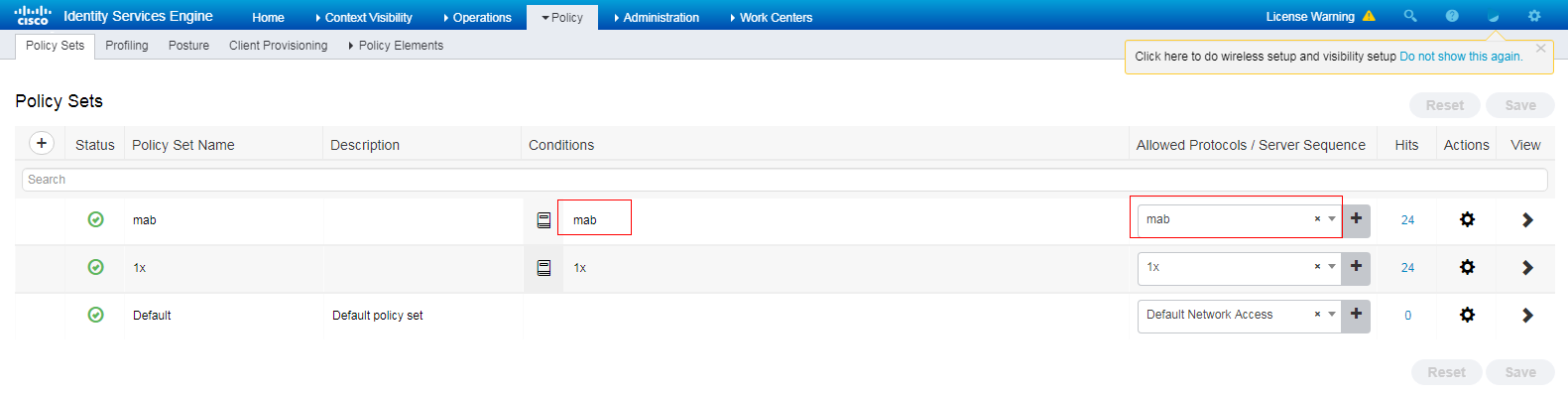
c. Set the policy set name to mab, set the conditions name to mab, and select mab from the Allowed Protocols/Server Sequence list.
Figure 19 Configuring an authentication and authorization policy set
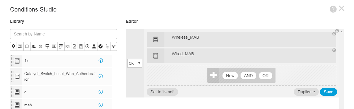
d. Select Wired_MAB or Wireless_MAB as the conditions.
Figure 20 Configuring conditions
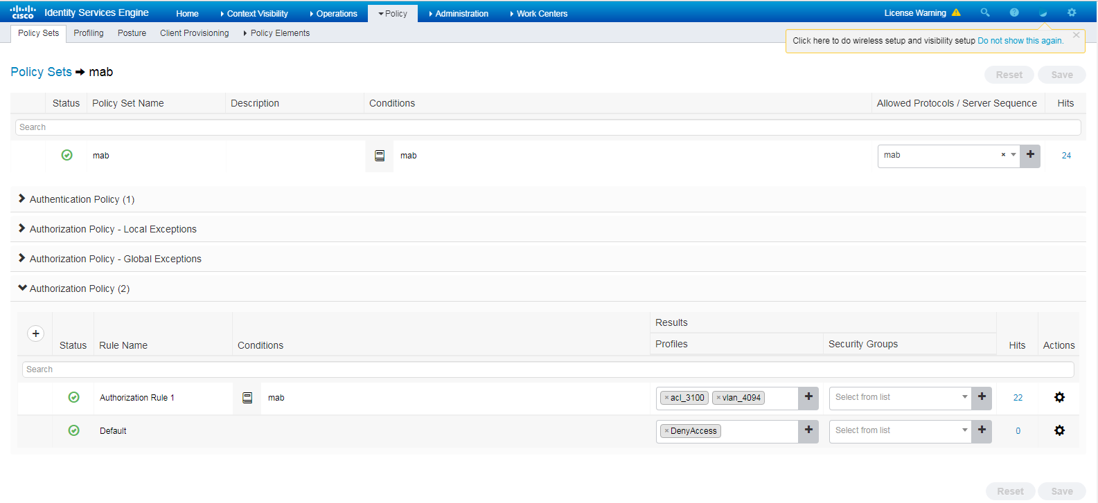
a. Click the icon in the View column for the authentication and authorization policy set.
b. In the Authorization Policy area, add an authorization policy named Authorization Rule 1. In the Results > Profiles column for the authorization policy, select profiles acl_3100 and vlan_4094.
Figure 21 Adding an authorization policy
g. Save the configuration.
Verifying the configuration
1. On the client, connect to the wireless network and enter the configured username and password. (Details not shown.)
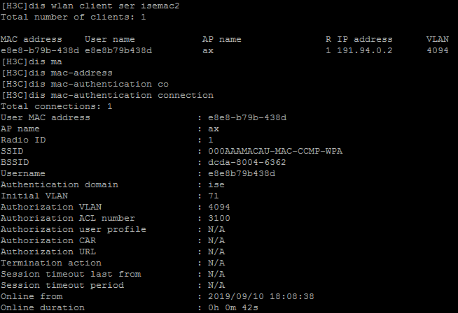
2. On the AC, verify that the user has come online and the server has assigned the authorization ACL and VLAN to the user.
Figure 22 Viewing online user information
Configuration files
#
vlan 4094
#
dhcp server ip-pool vlan4094
network 191.94.0.0 mask 255.255.255.0
gateway-list 191.94.0.1
dns-list 191.94.0.1
#
interface vlan-interface 4094
ip address 191.94.0.1 24
#
acl advanced 3100
rule 1 deny ip destination 8.1.1.5 0
#
radius scheme ise
primary authentication 8.1.1.19 key cipher $c$3$FpBySjKd6TF17QmPAQ83vNM+mNuZHUw=
user-name-format without-domain
nas-ip 191.120.1.56
#
domain ise
authentication default radius-scheme ise
authorization default radius-scheme ise
#
wlan ap ax model WA6528
serial-id 219801A1LH8188E00011
#
wlan service-template isemac2
ssid 000AAAMACAU-MAC-CCMP-WPA
vlan 71
akm mode psk
preshared-key pass-phrase cipher $c$3$XYqokG6I8YoOymukIyvxoJuzFoB+oVJD6exoqw==
cipher-suite ccmp
security-ie rsn
client-security authentication-mode mac
mac-authentication domain ise
service-template enable
#
wlan ap ax model WA6528
serial-id 219801A1LH8188E00011
vlan 1
radio 1
radio enable
service-template isemac2
Example: Configuring Cisco ISE-based portal authentication
Network configuration
As shown in Figure 23, the AP is connected to the AC over the switch and the client accesses the wireless network through the AP.
Configure the devices and server to meet the following requirements:
· The client must pass direct portal authentication to access the wireless network.
· The ISE server acts as the portal and RADIUS servers.

Restrictions and guidelines
Make sure file ise_h3c.zip has been stored in the root directory of the storage medium on the AC.
Procedures
|
|
IMPORTANT: This configuration example only covers the major settings related to authenticating the client by portal authentication on the Cisco ISE server. For information about the network connectivity settings, see the manuals for the devices and server. Make sure the devices and server have network connectivity. |
Configuring the AC
1. Configure an ISP domain:
# Create ISP domain ise.
<H3C> system-view
[H3C] domain ise
# Configure the ISP domain to use RADIUS scheme ise for portal user authentication, authorization, and accounting.
[H3C-isp-ise] authentication portal radius-scheme ise
[H3C-isp-ise] authorization portal radius-scheme ise
[H3C-isp-ise] accounting portal radius-scheme ise
[H3C-isp-ise] quit
2. Configure a RADIUS scheme:
# Create RADIUS scheme ise.
[H3C] radius scheme ise
# Specify the ISE server at 100.18.0.200 as the primary authentication and accounting servers and specify a shared key for secure communication with the ISE server. Make sure the shared key is the same as the shared secret configured on the ISE server.
[H3C-radius-ise]primary authentication 100.18.0.200 key simple 12345678
[H3C-radius-ise]primary accounting 100.18.0.200 key simple 12345678
# Exclude the domain name from usernames sent to the ISE server.
[H3C-radius-ise]user-name-format without-domain
3. Configure portal authentication:
# Enable automatic logout for wireless portal users.
[H3C] portal user-logoff after-client-offline enable
# Specify VLAN-interface 1000 on the AC for clients to access during third-party authentication.
[H3C] portal client-gateway interface vlan-interface 1000
# Permit packets destined for the AC.
[H3C] portal free-rule 2 destination ip 6.6.4.10 255.255.255.255
# Permit packets destined for the RADIUS server.
[H3C] portal free-rule 5 destination ip 100.18.0.200 255.255.255.255
# Configure the Web server.
|
|
NOTE: For more information about the URL of the Web server, see portal settings in "Configuring the ISE server." |
[H3C] portal web-server ise
[H3C-portal-websvr-ise] url https://100.18.0.200:8443/portal/PortalSetup.action?portal=f0ae43f0-7159-11e7-a355-005056aba474
[H3C-portal-websvr-ise] server-type ise
# Create an HTTP-based local portal Web service and an HTTPS-based local portal Web service. Specify file ise_h3c.zip as the default authentication page file for local portal authentication. Make sure the file has been stored in the root directory of the storage medium on the AC.
[H3C] portal local-web-server http
[H3C-portal-local-websvr-http] default-logon-page ise_h3c.zip
[H3C] portal local-web-server https
[H3C-portal-local-websvr-https] default-logon-page ise_h3c.zip
4. Configure and enable a service template.
[H3C] wlan service-template iseportal
[H3C-wlan-st-iseportal] ssid h3c-ise-portal
[H3C-wlan-st-iseportal] portal enable method direct
[H3C-wlan-st-iseportal] portal domain ise
[H3C-wlan-st-iseportal] portal bas-ip 6.6.4.10
[H3C-wlan-st-iseportal] portal apply web-server ise
[H3C-wlan-st-iseportal] service-template enable
[H3C-wlan-st-iseportal] quit
5. Configure a manual AP and bind the service template to radio 1 on the AP.
[H3C] wlan ap ap1 model WA6330
[H3C-wlan-ap-ap1] serial-id 219801A23V8209E0043Y
[H3C-wlan-ap-ap1] radio 1
[H3C-wlan-ap-ap1-radio-1] service-template iseportal vlan 234
[H3C-wlan-ap-ap1-radio-1] radio enable
[H3C-wlan-ap-ap1-radio-1] quit
[H3C-wlan-ap-ap1] quit
Configuring the ISE server
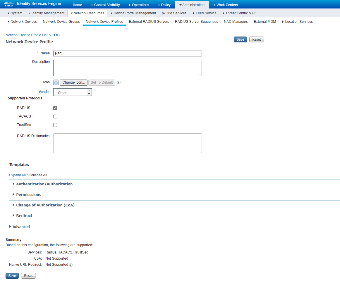
1. Create a device profile:
a. On the top navigation bar, select Administration > Network Resources > Network Device Profiles.
b. Click Add.
c. Set the device profile name to H3C, select Other as the vendor, and select RADIUS in the Supported Protocols area.
d. Save the configuration.
Figure 24 Creating a device profile
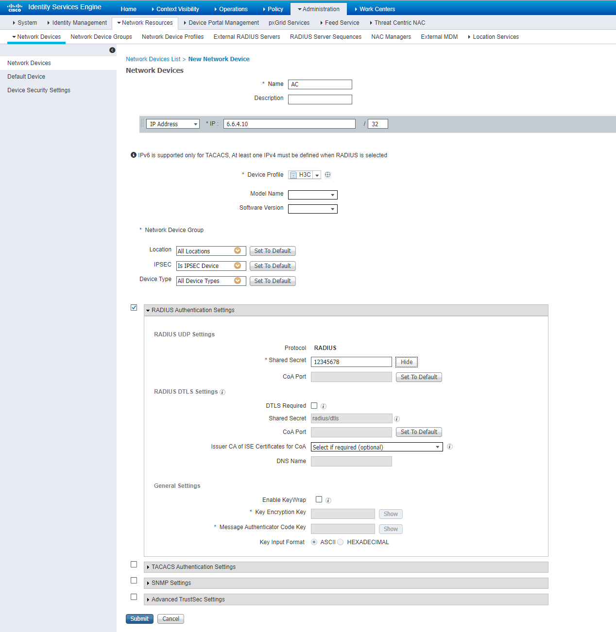
2. Add the AC to the server as a network access device:
a. On the top navigation bar, select Administration > Network Resources > Network Devices.
b. Click Add.
c. On the page that opens, set the name to AC, select device profile H3C, specify IP address 6.6.4.10, select RADIUS Authentication Settings, and set the shared secret to 12345678.
Make sure the IP address is the same as the NAS IP address of RADIUS packets on the AC.
Make sure the shared secret is the same as the shared key configured on the AC.
d. Click Submit.
Figure 25 Adding the AC to the server
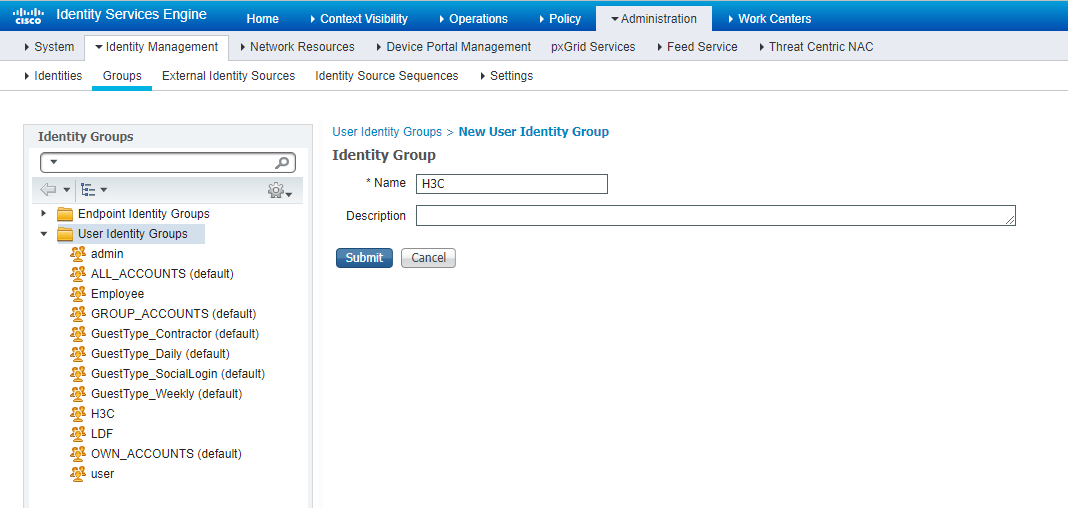
3. Create a user group:
a. On the top navigation bar, select Administration > Identity Management > Groups.
b. From the left navigation pane, select User Identity Groups.
c. Click Add.
d. On the page that opens, set the name to H3C.
e. Click Submit.
Figure 26 Creating a user group
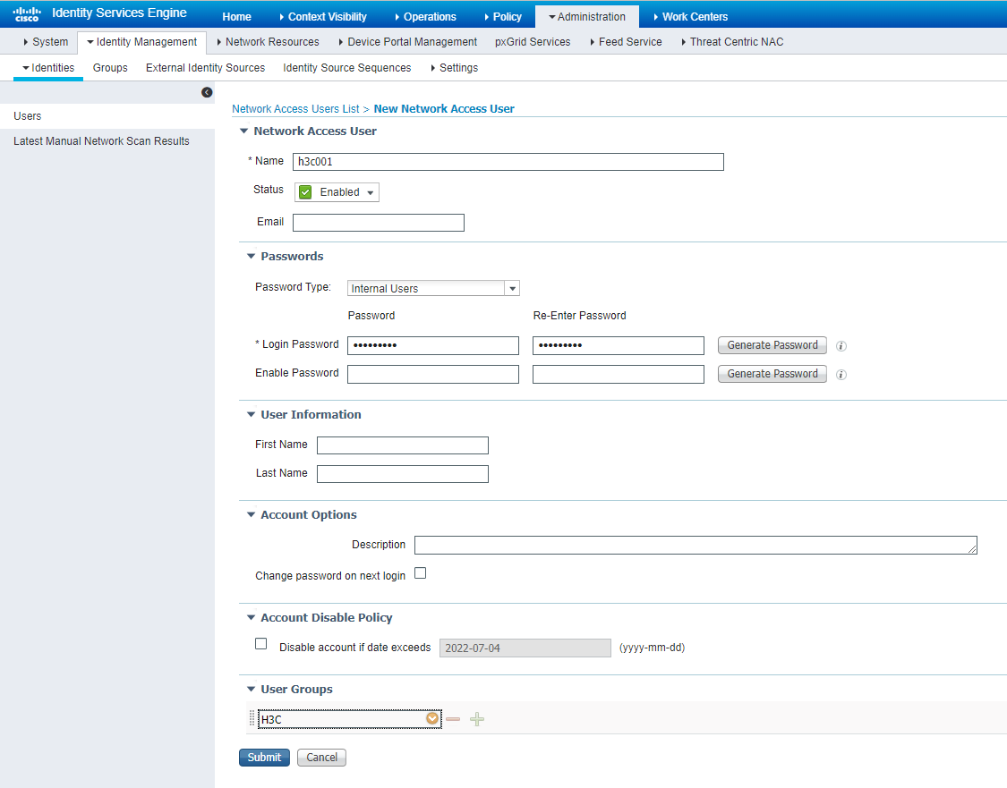
4. Create a network access user:
a. On the top navigation bar, select Administration > Identity Management > Identities.
b. From the left navigation pane, select Users.
c. Click Add.
d. On the page that opens, set the name to h3c001 and password to H3c123456, and bind the user to user group H3C.
Make sure the password contains uppercase letters, lowercase letters, and digits.
e. Click Submit.
Figure 27 Creating a network access user
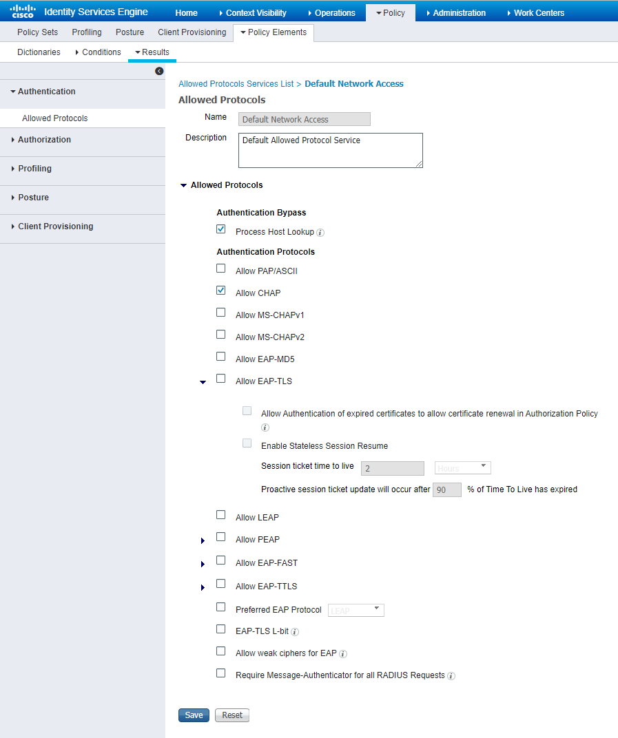
5. Configure authentication protocols:
a. On the top navigation bar, select Policy > Policy Elements > Results.
b. From the left navigation pane, select Authentication > Allowed Protocols.
c. Click Default Network Access and select Allow CHAP.
d. Save the configuration.
Figure 28 Configuring authentication protocols
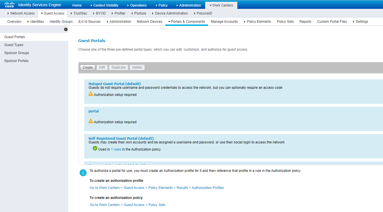
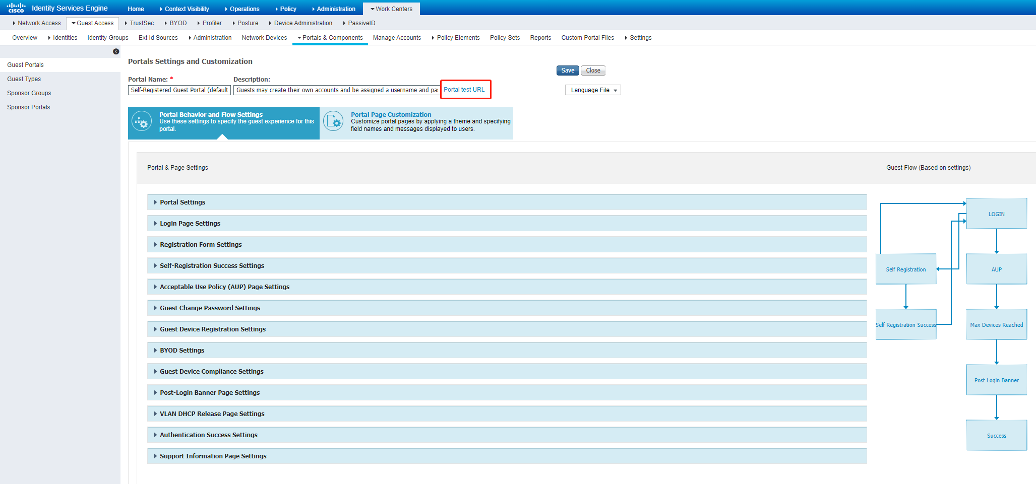
a. On the top navigation bar, select Work Centers > Guest Access > Portals & Components.
b. From the left navigation pane, select Guest Portals.
c. On the page that opens, click Self-Registered Guest Portal (default). Use the default settings, and then click Portal test URL. The address in the address bar of the window that opens is the address of the Web server.
Figure 29 Configuring portal settings
Verifying the configuration
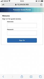
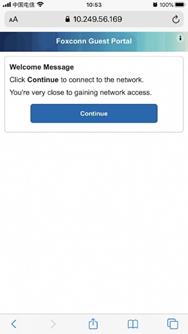
# On a mobile phone, connect to the wireless service with SSID h3c-ise-portal. When the Cisco authentication login page opens, enter the correct username and password, and then click Sign On. On the page that opens, click Continue. Verify that the login succeeds.
Figure 30 Verifying the configuration
# On the AC, display online portal user information.
[H3C] display portal user all
Total portal users: 1
Username: h3c001
AP name: ap1
Radio ID: 1
SSID: h3c-ise-portal
Portal server: N/A
State: Online
VPN instance: N/A
MAC IP VLAN Interface
9cbc-f0e7-50f0 10.249.56.169 234 WLAN-BSS1/0/4
Authorization information:
DHCP IP pool: N/A
User profile: N/A
Session group profile: N/A
ACL number: N/A
Inbound CAR: N/A
Outbound CAR: N/A
Web URL: N/A
Configuration files
#
vlan 234
#
vlan 1000
#
wlan service-template iseportal
ssid h3c-ise-portal
portal enable method direct
portal domain ise
portal bas-ip 6.6.4.10
portal apply web-server ise
service-template enable
#
interface Vlan-interface1000
ip address 6.6.4.10 255.255.255.0
#
radius scheme ise
primary authentication 100.18.0.200 key cipher $c$3$oTPE3ir9uYI718iL9tFmRoaoDu7
DmtlZ2gZC
primary accounting 100.18.0.200 key cipher $c$3$/Vcna21JU94hHKqWvBTrACCGhUm8iPi
B5Vp7
user-name-format without-domain
nas-ip 6.6.4.10
#
domain ise
authentication portal radius-scheme ise
authorization portal radius-scheme ise
accounting portal radius-scheme ise
#
portal user-logoff after-client-offline enable
portal client-gateway interface Vlan-interface1000
portal free-rule 2 destination ip 6.6.4.10 255.255.255.255
portal free-rule 5 destination ip 100.18.0.200 255.255.255.255
#
portal web-server ise
url https://100.18.0.200:8443/portal/PortalSetup.action?portal=f0ae43f0-7159-11e7-a355-005056aba474
server-type ise
#
portal local-web-server http
default-logon-page ise_h3c.zip
#
portal local-web-server https
default-logon-page ise_h3c.zip
#
wlan ap ap1 model WA6330
serial-id 219801A23V8209E0043Y
radio 1
radio enable
service-template iseportal vlan 234
radio 2
radio 3
#
Example: Configuring Cisco ISE-based HWTACACS authentication for SSH login
Network configuration
As shown in Figure 31, the PC is connected to the AC over the switch. The ISE server performs HWTACACS authentication for the client when the client logs in to the AC through SSH.
The client has the following permissions after it logs in to the AC through SSH:
· Has the permissions of the level-1 user role.
· Cannot access the display cpu-usage command.

Procedures
|
|
IMPORTANT: This configuration example only covers the major settings related to authenticating SSH login by HWTACACS authentication on the Cisco ISE server. For information about the network connectivity settings, see the manuals for the devices and server. Make sure the devices and server have network connectivity. |
Configuring the AC
1. Configure an HWTACACS scheme:
# Create HWTACACS scheme tac.
<AC> system-view
[AC] hwtacacs scheme tac
# Specify the ISE server at 8.1.1.19 as the primary authentication, authorization, and accounting servers and specify a shared key for secure communication with the ISE server. Make sure the shared key is the same as the shared secret configured on the ISE server.
[AC-hwtacacs-tac] primary authentication 8.1.1.19 key cipher $c$3$8zfqwa07HmNhvjWvEeixw5NGEGo82r/htRg=
[AC-hwtacacs-tac] primary authorization 8.1.1.19 key cipher $c$3$fARZu6PskfKoULCy46SHq0hVbNHakBUPleE=
[AC-hwtacacs-tac] primary accounting 8.1.1.19 key cipher $c$3$tBnfBlfHnO9YHBko2ZjMpzpuRqSyN3wdDPA=
# Exclude the domain name from usernames sent to the ISE server.
[AC-hwtacacs-tac] user-name-format without-domain
# Specify 191.2.1.56 as the NAS IP address of HWTACACS packets sent to the ISE server. Make sure the NAS IP address is the same as that specified on the ISE server for the AC.
[AC-hwtacacs-tac] nas-ip 191.2.1.56
[AC-hwtacacs-tac] quit
2. Configure an ISP domain:
# Create ISP domain system.
[AC] domain system
# Configure the ISP domain to use HWTACACS scheme tac for login user authentication and authorization and to not perform accounting for login users.
[AC-isp-system] authentication login hwtacacs-scheme tac
[AC-isp-system] authorization login hwtacacs-scheme tac
[AC-isp-system] accounting login none
# Configure the ISP domain to use HWTACACS scheme tac for command authorization and accounting.
[AC-isp-system] authorization command hwtacacs-scheme tac
[AC-isp-system] accounting command hwtacacs-scheme tac
[AC-isp-system] quit
3. Create local RSA and DSA key pairs and enable the SSH server.
[AC] public-key local create rsa
[AC] public-key local create dsa
[AC] ssh server enable
4. Enable the default role feature.
[AC] role default-role enable
5. Enable command authorization and accounting.
[AC] line vty 0 31
[AC-line-vty0-31] authentication-mode scheme
[AC-line-vty0-31] command authorization
[AC-line-vty0-31] command accounting
[AC-line-vty0-31] quit
Configuring the ISE server
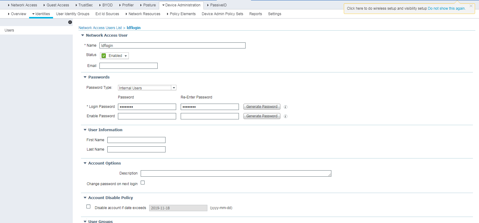
1. Create a network access user:
a. On the top navigation bar, select Work Centers > Device Administration > Identities.
b. From the left navigation pane, select Users.
c. Click Add.
d. On the page that opens, set the name to ldflogin and password to Ldf654321.
Make sure the password contains uppercase letters, lowercase letters, and digits.
e. Click Submit.
Figure 32 Creating a network access user
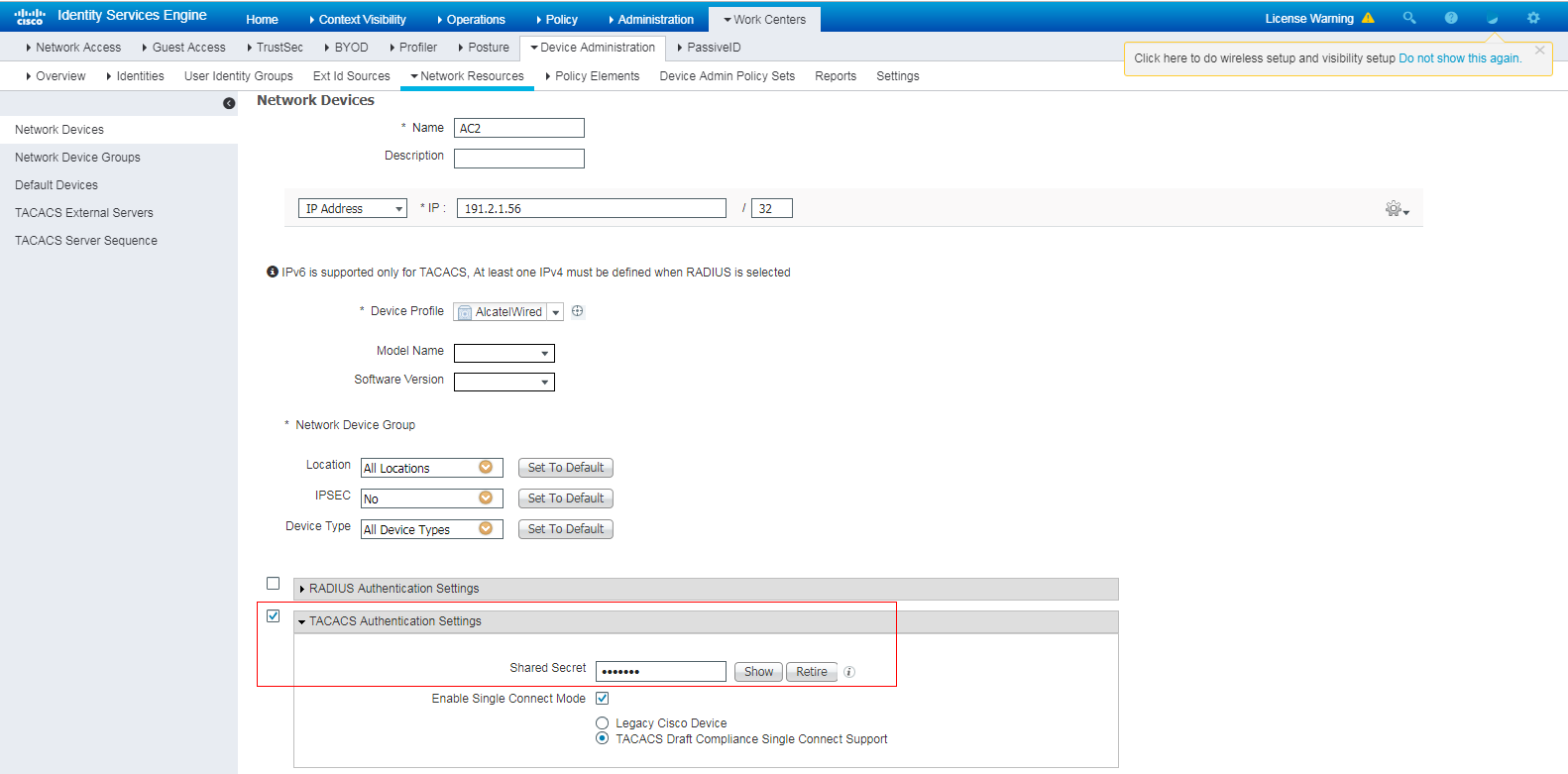
2. Add the AC to the server as a network access device:
a. On the top navigation bar, select Work Centers > Device Administration > Network Resources.
b. From the left navigation pane, select Network Devices.
c. Click Add.
d. On the page that opens, set the name to AC2, specify IP address 191.2.1.56, select TACACS Authentication Settings, and set the shared secret to H3cc.
Make sure the IP address is the same as the NAS IP address of HWTACACS packets on the AC.
Make sure the shared secret is the same as the shared key configured on the AC.
e. Save the configuration.
Figure 33 Adding the AC to the server
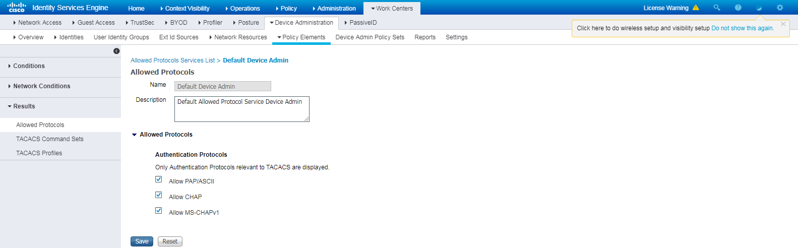
3. Configure authentication protocols:
a. On the top navigation bar, select Work Centers > Device Administration > Policy Elements.
b. From the left navigation pane, select Results > Allowed Protocols.
c. Use the default allowed protocols service named Default Device Admin.
Figure 34 Configuring authentication protocols
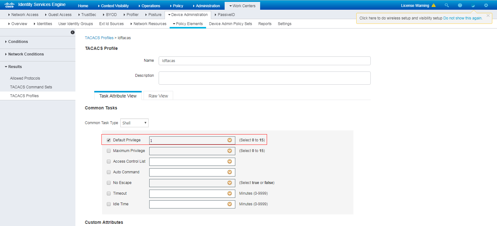
4. Configure a TACACS profile:
a. On the top navigation bar, select Work Centers > Device Administration > Policy Elements.
b. From the left navigation pane, select Results > TACACS Profiles.
c. Click Add.
d. On the page that opens, set the name to ldftacas, select Default Privilege, and set the default privilege to level 1.
e. Save the configuration.
Figure 35 Configuring a TACACS profile
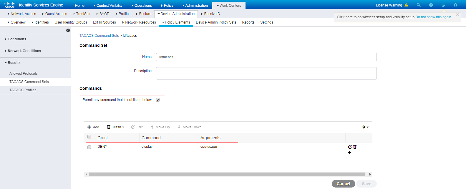
5. Configure a TACACS command set:
a. On the top navigation bar, select Work Centers > Device Administration > Policy Elements.
b. From the left navigation pane, select Results > TACACS Command Sets.
c. Click Add.
d. On the page that opens, set the name to ldftacacs. In the Commands area, select Permit any command that is not listed below and deny the display cpu-usage command.
e. Save the configuration.
Figure 36 Configuring a TACACS command set
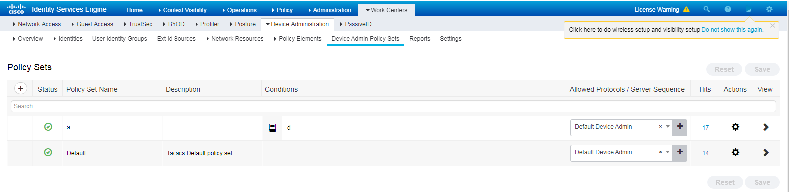
6. Configure an authentication and authorization policy set:
a. On the top navigation bar, select Work Centers > Device Administration > Device Admin Policy Sets.
b. Click the plus icon + under Policy Sets.
c. Set the policy set name to a.
Figure 37 Configuring an authentication and authorization policy set
d. Click the icon in the View column for the authentication and authorization policy set named a.
e. In the Authorization Policy area, add an authorization policy named Authorization Rule 1. In the Results > Command Sets column for the authorization policy, select command set ldftacacs. In the Results > Shell Profiles column for the authorization policy, select TACACS profile ldftacas.
Figure 38 Adding an authorization policy
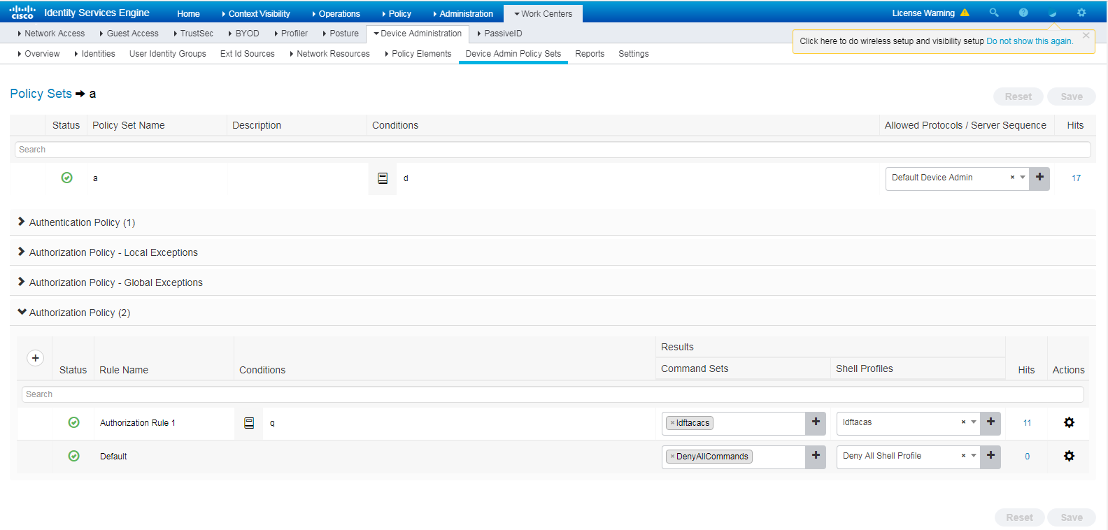
f. Save the configuration.
7. Enable device access authentication service:
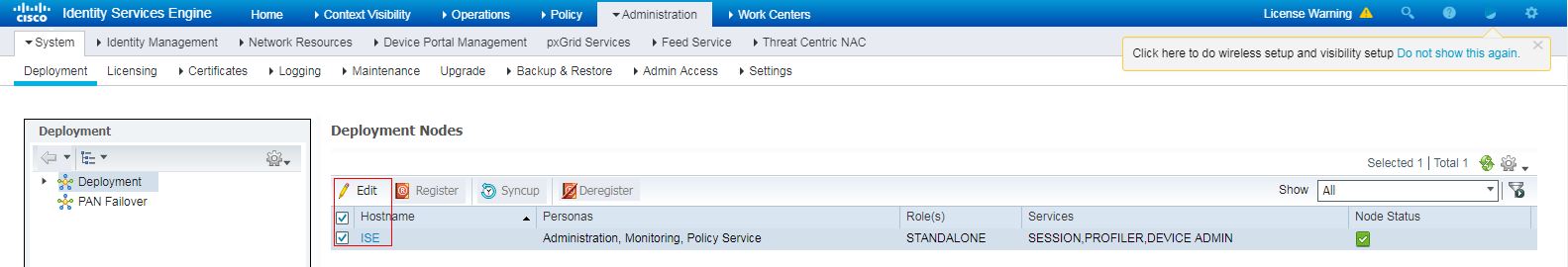
a. On the top navigation bar, select Administration > System > Deployment.
b. Select the ISE node, and then click Edit.
Figure 39 Selecting the ISE node and clicking Edit
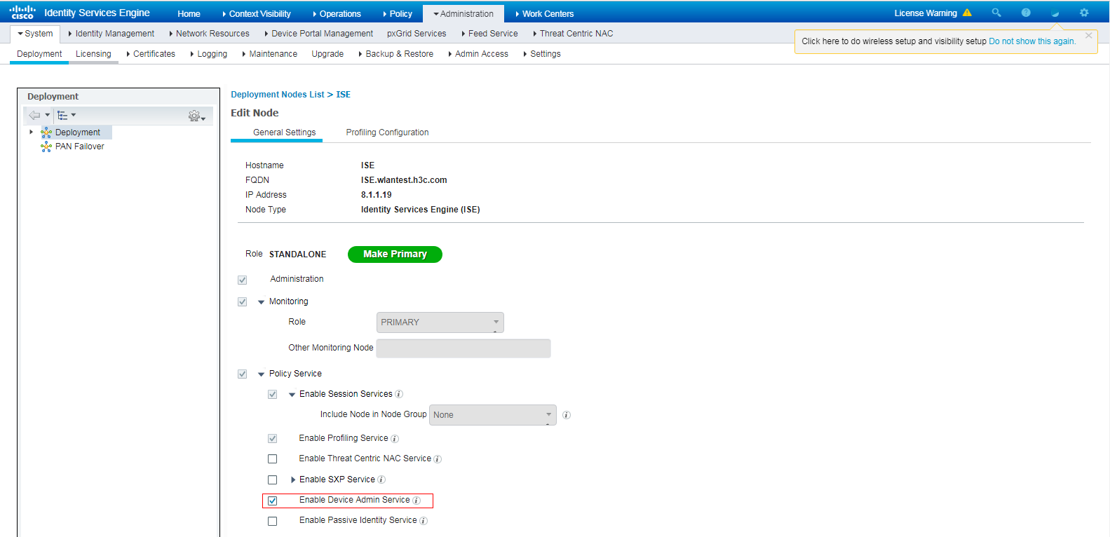
c. On the page that opens, select the Enable Device Admin Service option and save the configuration.
Figure 40 Editing the ISE node
Verifying the configuration
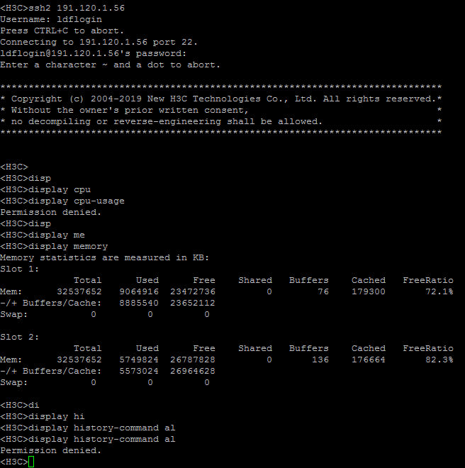
1. Verify that the client can log in to the AC through SSH after it provides the correct username and password. (Details not shown.)
2. Verify that the client can access only commands permitted by the level-1 role. For example, the client can access the display memory command. Verify that the client cannot access the display cpu-usage command.
Figure 41 Verifying the access permissions
Configuration files
#
hwtacacs scheme tac
primary authentication 8.1.1.19 key cipher $c$3$8zfqwa07HmNhvjWvEeixw5NGEGo82r/htRg=
primary authorization 8.1.1.19 key cipher $c$3$fARZu6PskfKoULCy46SHq0hVbNHakBUPleE=
primary accounting 8.1.1.19 key cipher $c$3$tBnfBlfHnO9YHBko2ZjMpzpuRqSyN3wdDPA=
user-name-format without-domain
nas-ip 191.2.1.56
#
domain system
authentication login hwtacacs-scheme tac
authorization login hwtacacs-scheme tac
accounting login none
authorization command hwtacacs-scheme tac
accounting command hwtacacs-scheme tac
#
public-key local create rsa
#
public-key local create dsa
#
ssh server enable
#
role default-role enable
#
line vty 0 31
authentication-mode scheme
command authorization
command accounting
Example: Configuring Cisco ISE-based LDAP authentication
Network configuration
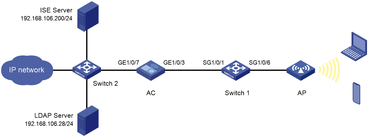
As shown in Figure 42:
· The AC is connected to core switch Switch 2, and it can reach the ISE server and the LDAP server.
· The AP is connected to access switch Switch 1.
· The AC uses the usernames and passwords stored on the LDAP server to authenticate 802.1X users when the users access the network.
Restrictions and guidelines
· Use the serial ID labeled on the AP's rear panel to specify an AP.
· Make sure the LDAP server has been set up. In this example, the Active Directory of Microsoft Windows Server 2012 is used to illustrate the basic LDAP server configuration.
Procedures
Configuring the AC
1. Configure a RADIUS scheme:
# Create RADIUS scheme imc and enter its view.
[AC] radius scheme ise
# Specify the server at 192.168.106.200 as the primary authentication server and set the shared key to a plaintext string of 12345678.
[AC-radius-ise] primary authentication 192.168.106.200 key simple 12345678
# Specify the server at 192.168.106.200 as the primary accounting server and set the shared key to a plaintext string of 12345678.
[AC-radius-ise] primary accounting 192.168.106.200 key simple 12345678
# Exclude the domain name from the usernames sent to the server.
[AC-radius-ise] user-name-format without-domain
# Specify IP address 192.168.105.36 as the source IP address of outgoing RADIUS packets.
[AC-radius-ise] nas-ip 192.168.105.36
[AC-radius-ise] quit
2. Configure the AC to use EAP relay to authenticate 802.1X clients.
[AC] dot1x authentication-method eap
3. Configure an ISP domain:
# Create ISP domain ise and enter its view.
[AC] domain ise
# Configure the ISP domain to use RADIUS scheme ise for LAN user authentication and authorization and not perform accounting for LAN users.
[AC-isp-ise] authentication lan-access radius-scheme ise
[AC-isp-ise] authorization lan-access radius-scheme ise
[AC-isp-ise] accounting lan-access none
[AC-isp-ise] quit
4. Configure a service template:
# Create service template h3c-ise-ldap and enter its view.
[AC] wlan service-template h3c-ise-ldap
# Set the SSID of the service template to h3c-ise-ldap.
[AC-wlan-st-h3c-ise-ldap] ssid h3c-ise-ldap
# Set the AKM mode to 802.1X authentication.
[AC-wlan-st-h3c-ise-ldap] akm mode dot1x
# Assign clients that come online through the service template to VLAN 33.
[AC-wlan-st-h3c-ise-ldap] vlan 33
# Set the cipher suite to CCMP and enable the RSN-IE in beacon and probe responses.
[AC-wlan-st-h3c-ise-ldap] cipher-suite ccmp
[AC-wlan-st-h3c-ise-ldap] security-ie rsn
# Set the access authentication mode to 802.1X authentication.
[AC-wlan-st-h3c-ise-ldap] client-security authentication-mode dot1x
# Specify ISP domain ise as the 802.1X authentication domain.
[AC-wlan-st-h3c-ise-ldap] dot1x domain ise
# Enable the service template.
[AC-wlan-st-h3c-ise-ldap] service-template enable
[AC-wlan-st-h3c-ise-ldap] quit
5. Bind service template h3c-ise-ldap to radio 1 on manual AP ap1.
[AC] wlan ap ap1 model WA6622
[AC-wlan-ap-ap1] radio 1
[AC-wlan-ap-ap1] radio enable
[AC-wlan-ap-ap1] service-template h3c-ise-ldap
Configuring the LDAP server (adding a user account)
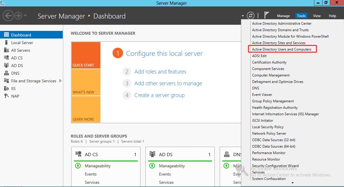
1. On the LDAP server, select Start > Control Panel > Administrative Tools.
2. Double-click Active Directory Users and Computers.
The Active Directory Users and Computers window is displayed.
Figure 43 Active Directory Users and Computers window
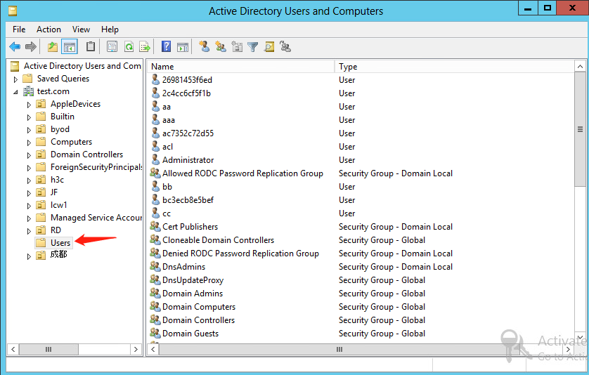
3. From the navigation pane, click Users under the test.com node.
Figure 44 Users window
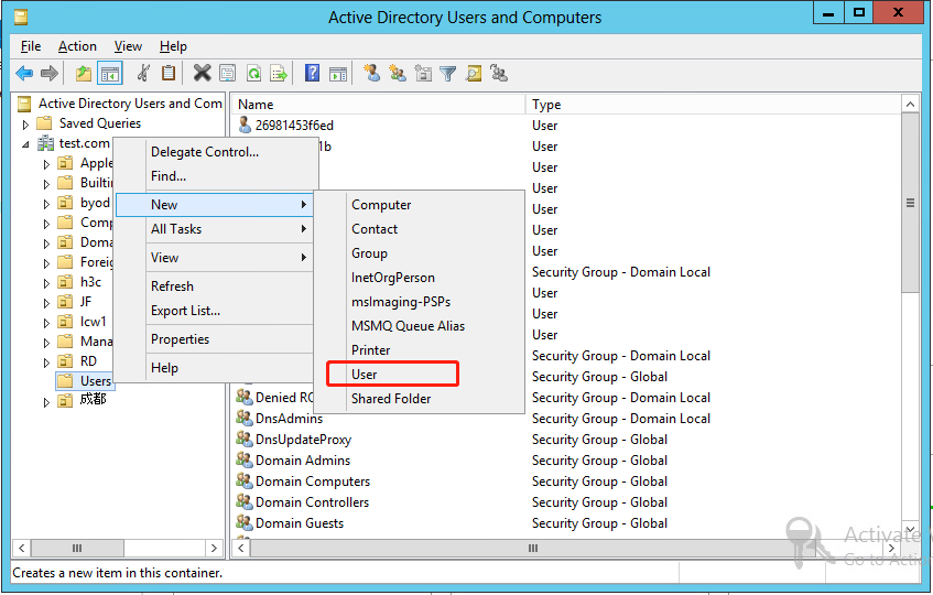
4. Right-click Users, and select New > User from the shortcut menu to display the dialog box for adding a user.
Figure 45 Opening the dialog box for adding a user
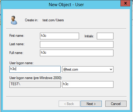
5. In the dialog box, set the first name, full name, and user logon name to h3c, and then click Next.
Figure 46 Entering the first name, full name, and user logon name
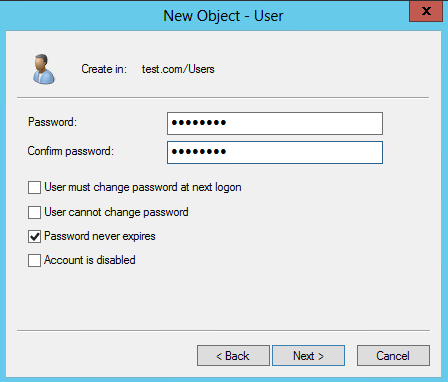
6. In the dialog box that opens, configure and confirm the password of the user, select options as needed, and click Next.
Figure 47 Setting the user's password
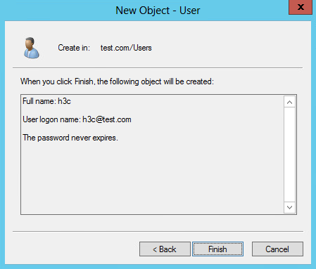
7. Finish creating the user.
Figure 48 Finishing creating the user
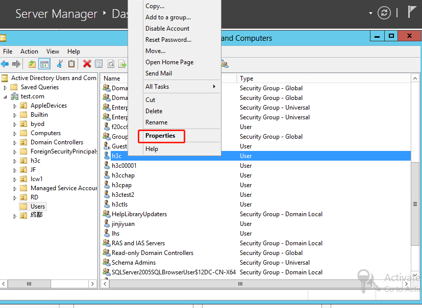
8. From the navigation pane, click Users under the test.com node. In the right pane, right-click user h3c and select Properties.
Figure 49 Selecting the Properties option for the user
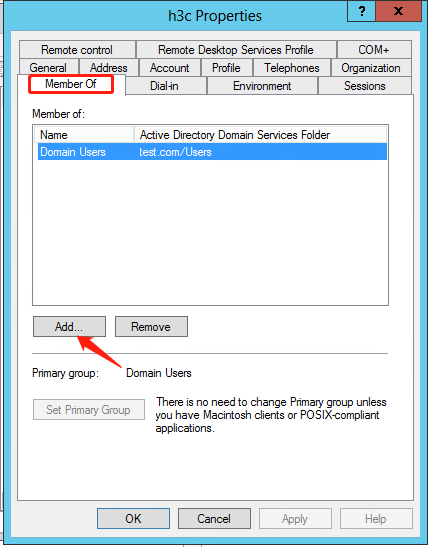
9. In the dialog box that opens, click the Member Of tab, and then click Add.
Figure 50 Opening the dialog box for adding the user to a user group
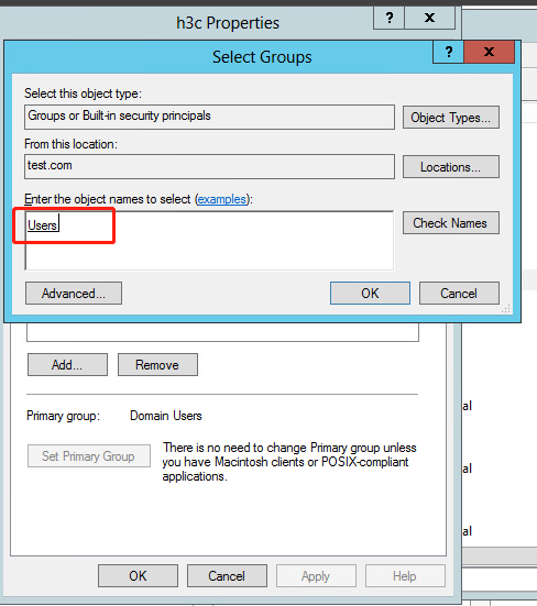
10. In the Select Groups dialog box, enter Users in the Enter the object names to select field, and click OK.
User h3c is added to group Users.
Figure 51 Adding user h3c to group Users
Configuring the ISE server
1. Create a network device profile:
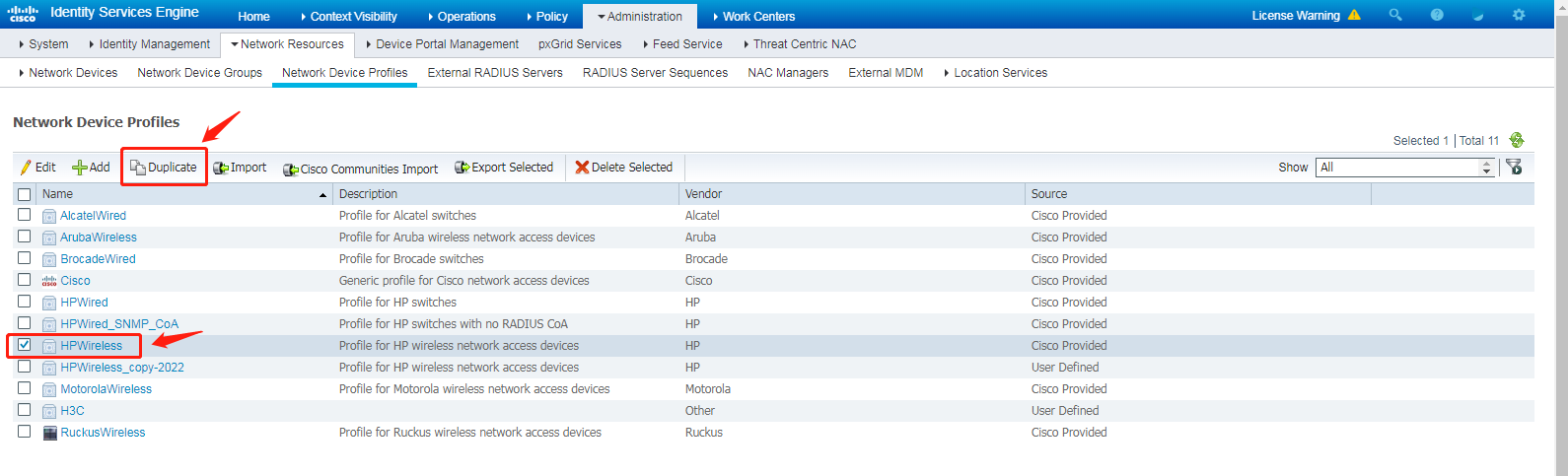
a. On the top navigation bar, select Administration > Network Resources > Network Device Profiles.
b. Select HPWireless, and then click Duplicate to open the page for adding a network device profile.
Figure 52 Network Device Profiles page
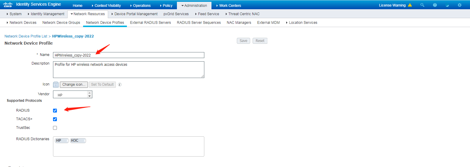
c. Set the profile name to HPWireless_copy-2022, select RADIUS in the Supported Protocols area, and then click Save.
Figure 53 Configuring the network device profile
2. Add the AC to the server as a network access device:
a. On the top navigation bar, select Administration > Network Resources > Network Devices.
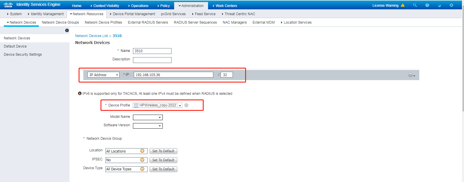
b. Click Add.
c. On the page that opens, set the name to 3510, specify IP address 192.168.105.36, and select device profile HPWireless_copy-2022.
Make sure the IP address on the ISE server is the same as the source IP address of outgoing RADIUS packets configured in the RADIUS scheme on the AC.
Figure 54 Adding the AC to the server as a network access device
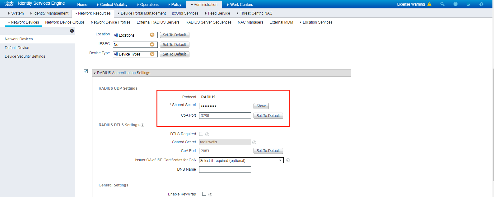
d. Configure the shared secret. Make sure the shared secret is the same as the shared key configured in the RADIUS scheme on the AC.
Figure 55 Configuring the shared secret
3. Add the LDAP server to the ISE server:
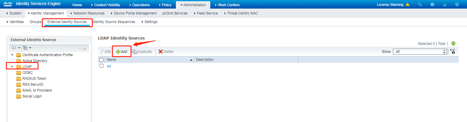
a. On the top navigation bar, click Administration > Identity Management > External Identity Sources.
b. From the left navigation pane, select LDAP.
c. Click Add.
Figure 56 Opening the page for adding an LDAP server
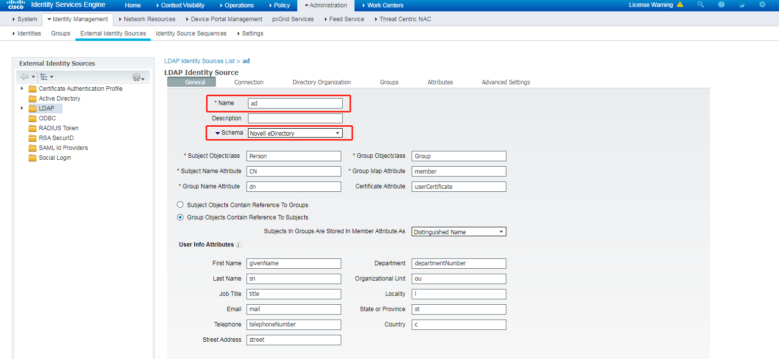
d. On the General tab, configure the LDAP server name and select Novell eDirectory from the schema list.
Figure 57 Configuring the LDAP server name
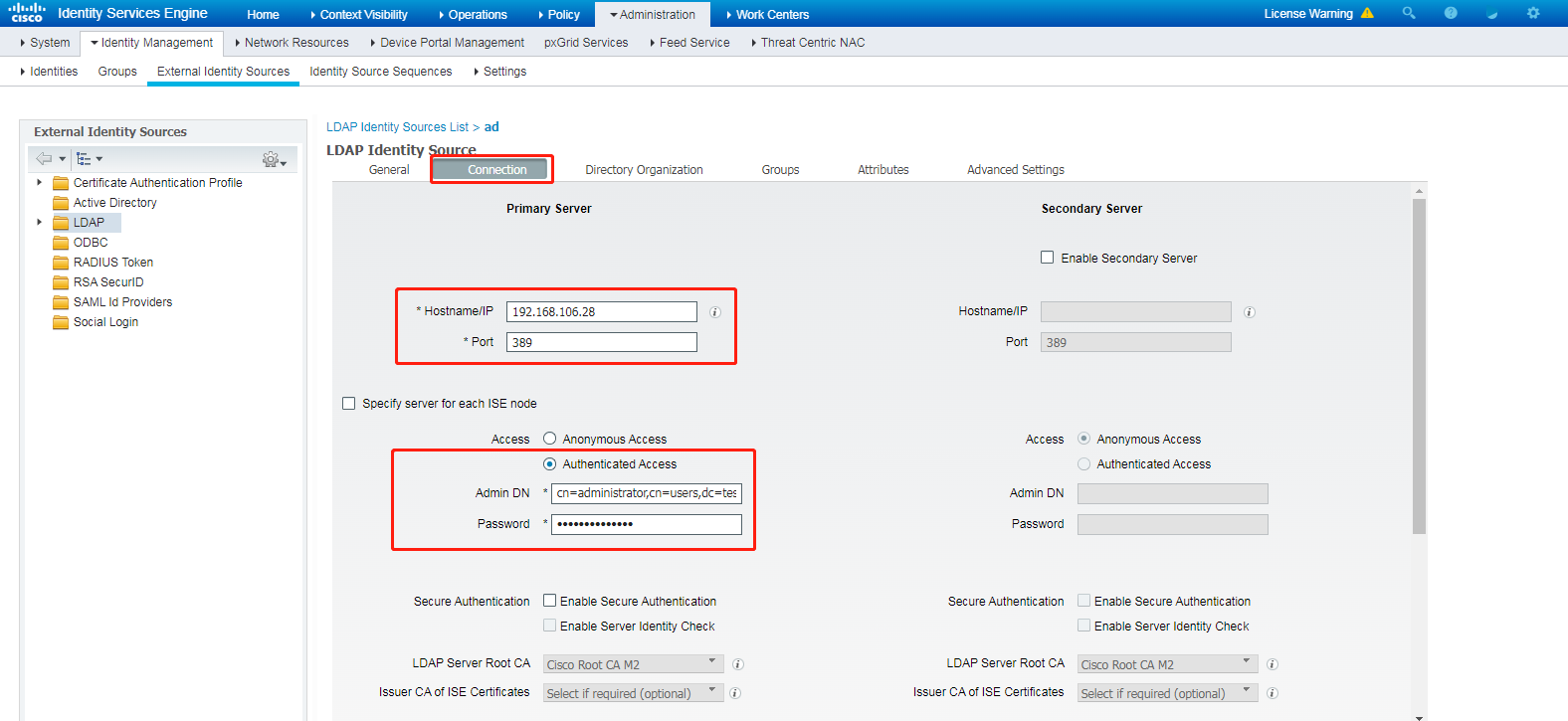
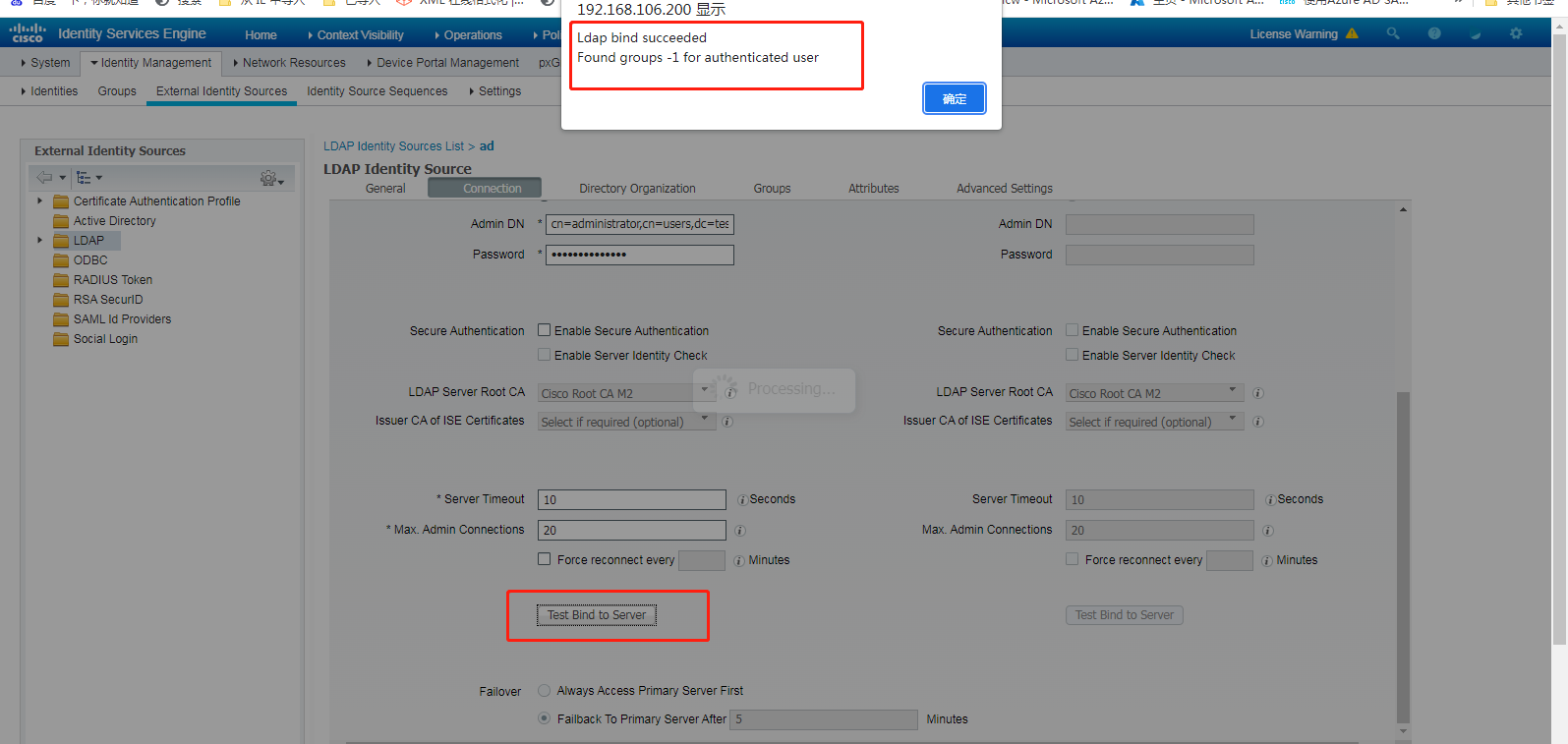
e. Click the Connection tab. On this tab, enter the IP address and port number of the LDAP server. By default, the port number is 389. You do not need to change the port number. Select Authenticated Access in the Access field, set the admin DN to cn=administrator,cn=users,dc=test,dc=com, and configure the password of the administrator on the LDAP server as the password.
Figure 58 Configuring LDAP server parameters
f. Click Test Bind to Server to test the connectivity between the ISE server and the LDAP server. The ISE server will display a message to indicate whether the binding is successful.
Figure 59 Testing the connectivity between the ISE server and the LDAP server
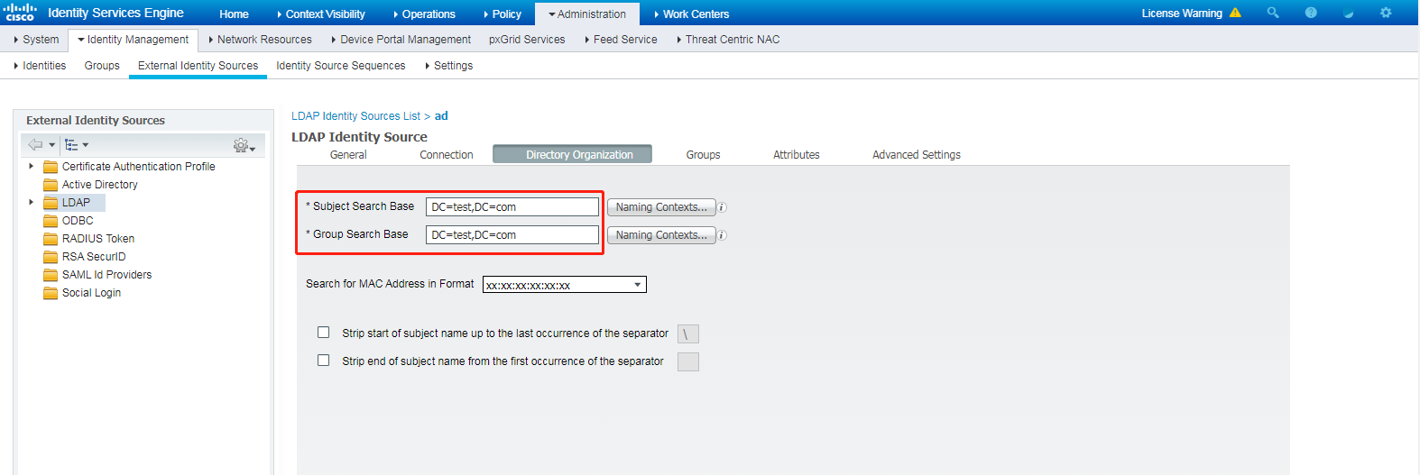
g. Click the Directory Organization tab, and enter DC=test,DC=com in both the Subject Search Base and Group Search Base fields.
Figure 60 Directory Organization tab
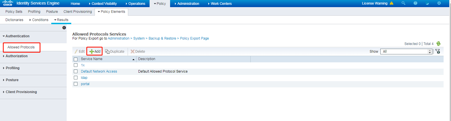
4. Configure authentication protocols:
a. On the top navigation bar, select Policy > Policy Elements > Results.
b. From the left navigation pane, select Authentication > Allowed Protocols.
c. Click Add.
Figure 61 Adding an allowed protocol service
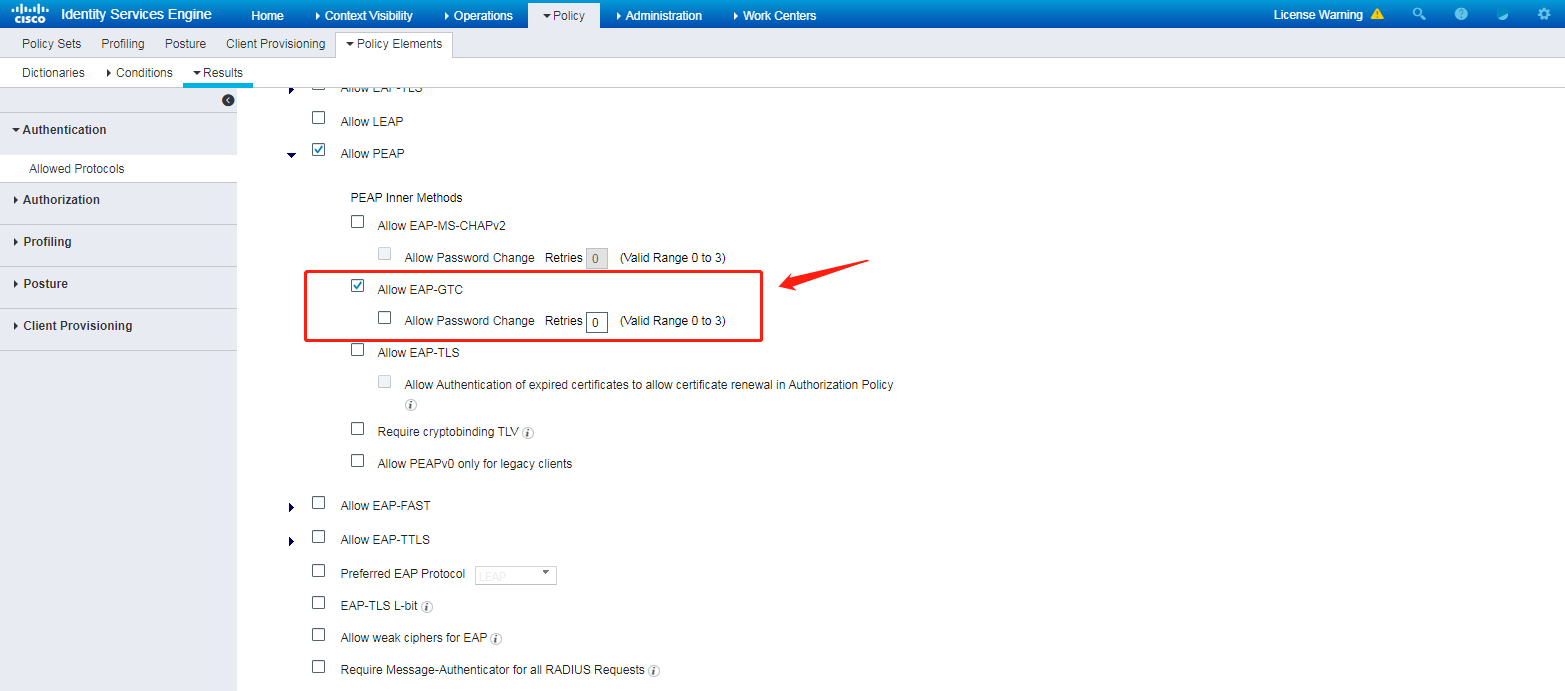
d. Set the name to ldap, and select only PAP/ASCII and PEAP-GTC from the authentication protocol list, as shown in Figure 62 and Figure 63.
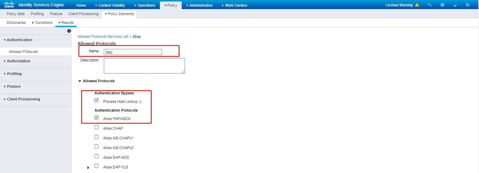
Figure 63 Selecting allowed authentication protocols
5. Configure an authentication and authorization policy set:
a. On the top navigation bar, select Policy > Policy Sets.
b. Click the plus icon + under Policy Sets.
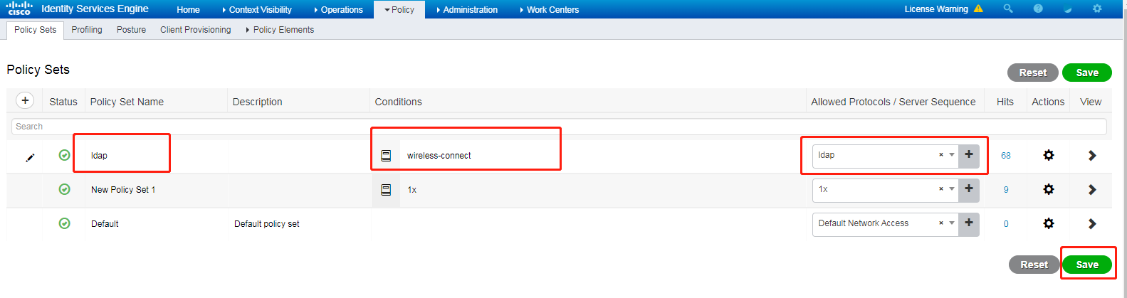
c. Set the policy set name to ldap, set the Conditions field to wireless-connect, and select ldap from the Allowed Protocols/Server Sequence list.
d. Click Save.
Figure 64 Configuring an authentication and authorization policy set
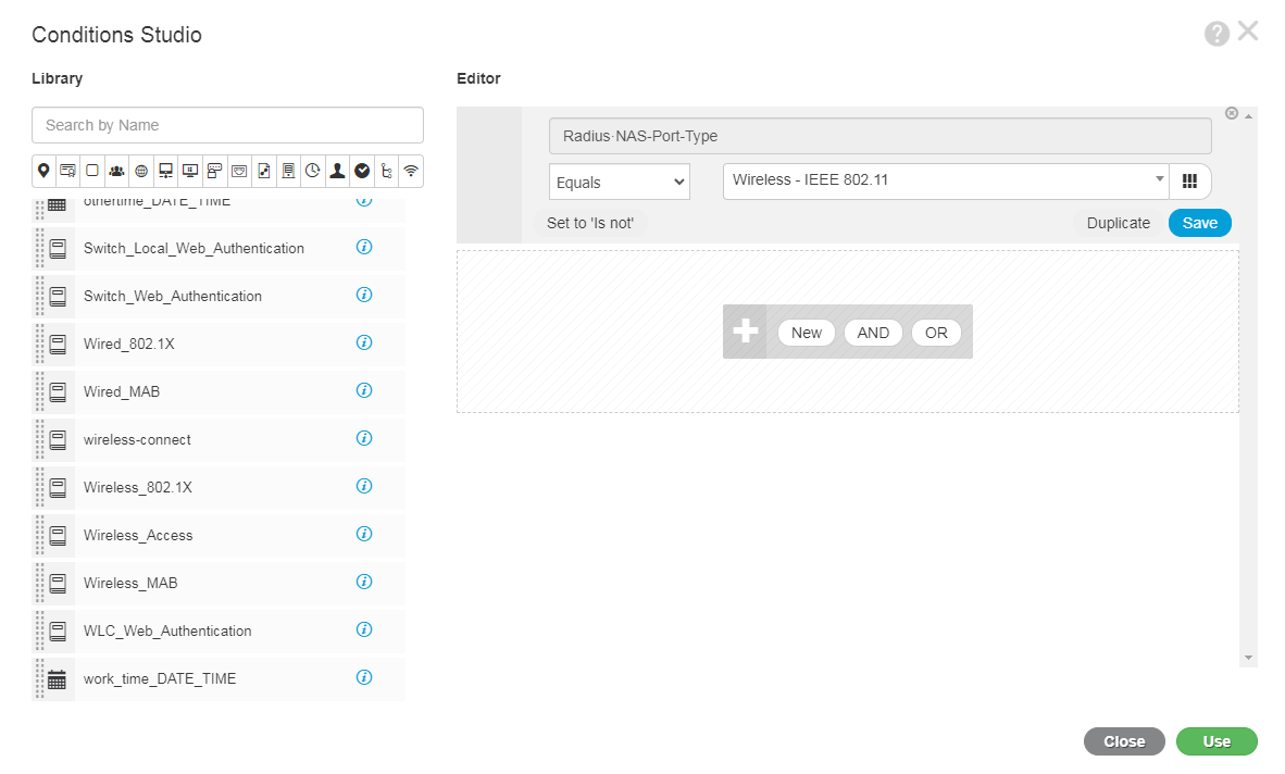
e. In the Conditions Studio dialog box, select wireless-connect as the conditions. In the Editor area, set the Radius·NAS-Port-Type field to Wireless-IEEE 802.11 to match wireless access users.
Figure 65 Configuring match conditions
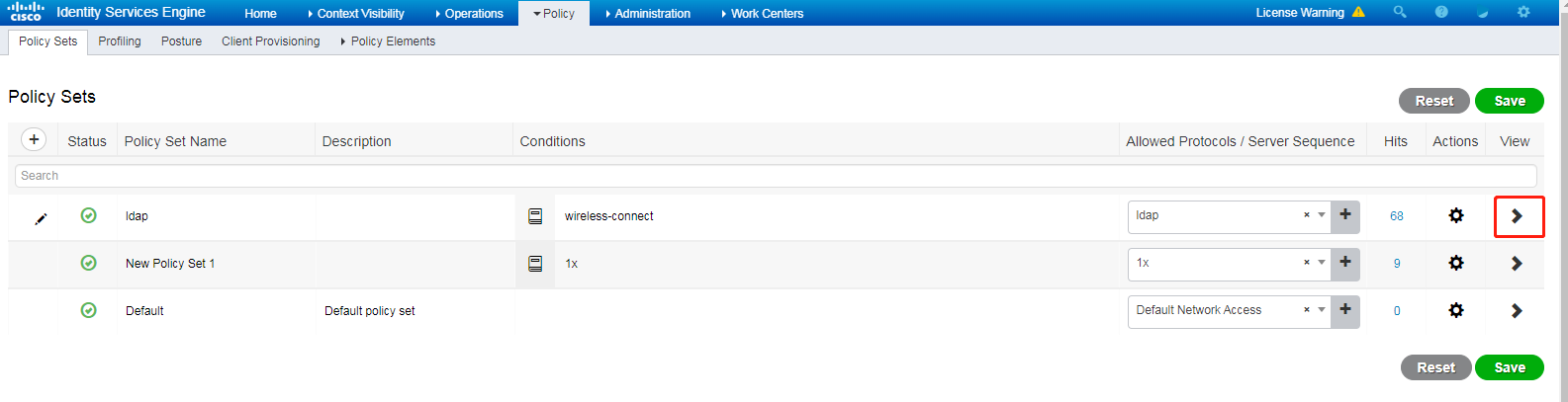
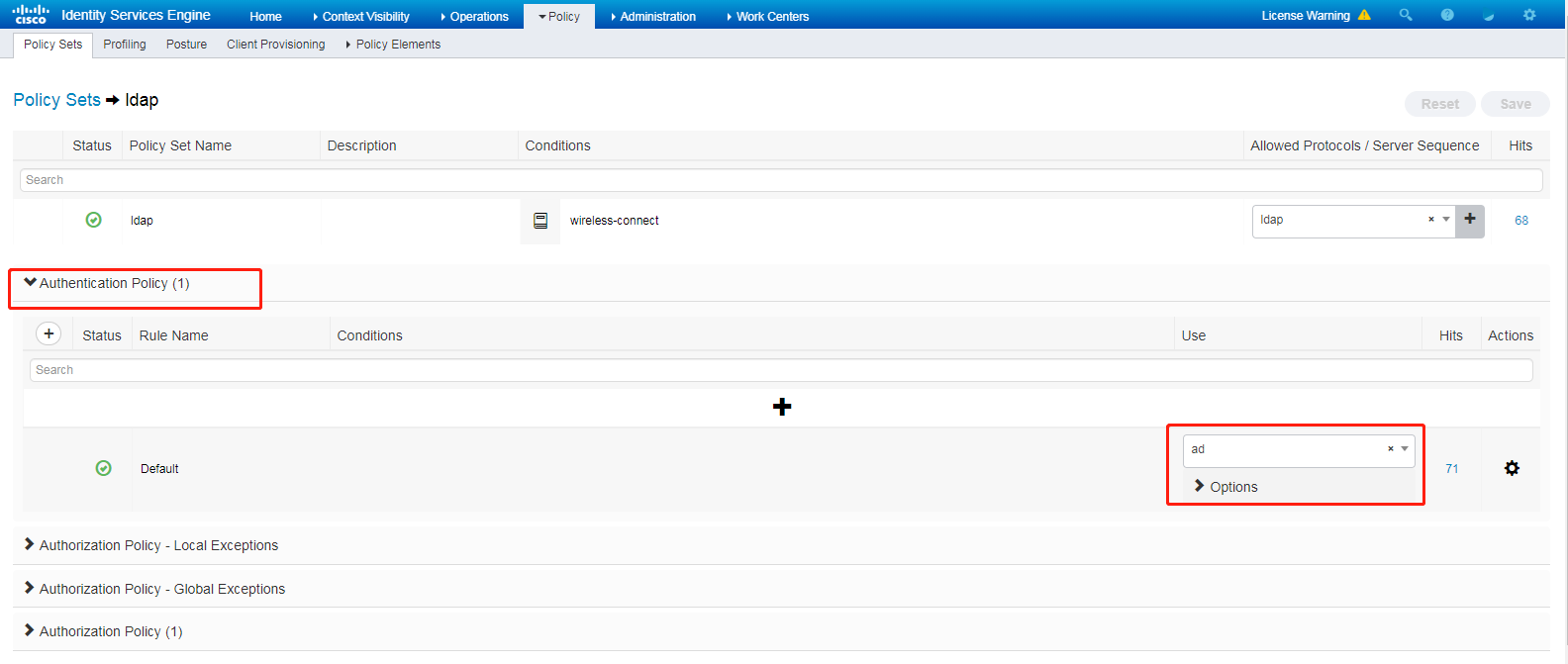
f. Click the icon in the View column for the authentication and authorization policy set.
Figure 66 Opening the page for configuring authentication and authorization settings
g. In the Authentication Policy (1) area, select ad (LDAP server name) in the Use column. The ISE server will use the LDAP server as the database for identity authentication. For more information about the LDAP server configuration, see step 3.
Figure 67 Specifying the LDAP server as the identity authentication database
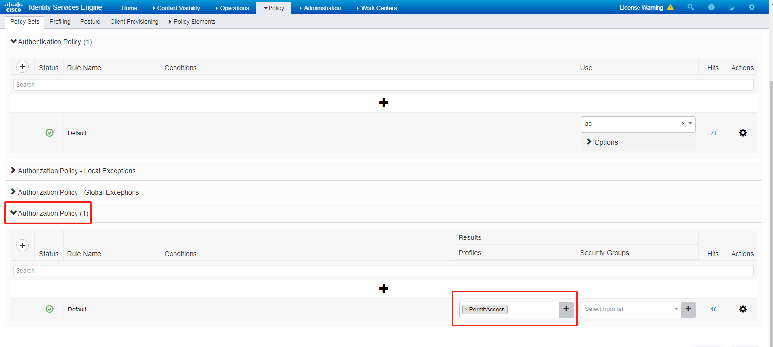
h. In the Authorization Policy (1) area, set the results to PermitAccess, and then click Save.
Figure 68 Configuring the authorization results
Verifying the configuration
# Use a wireless endpoint to connect to the wireless network. On the endpoint, use username h3c to initiate 802.1X authentication.
The configuration for connecting to the wireless network varies by endpoint operating system.
· On an Android endpoint, select PEAP as the EAP method and select GTC for phase 2 authentication in addition to entering the username and password.
· On an IOS or MAC OS endpoint, you only need to enter the username and password.
· On a Windows endpoint, you need to install the iNode client, configure wireless connection settings, and select the EAP-GTC authentication method from 802.1X properties, in addition to entering the username and password.
# On the AC, display online 802.1X user information.
[AC] display dot1x connection
Total connections: 1
User MAC address : b4a5-acd5-135d
AP name : ap1
Radio ID : 1
SSID : h3c-ise-ldap
BSSID : f474-88c3-60a5
Username : h3c
Anonymous username : N/A
Authentication domain : ise
IPv4 address : 174.33.0.3
Authentication method : EAP
Initial VLAN : 33
Authorization VLAN : 33
Authorization ACL number : N/A
Authorization user profile : N/A
Authorization CAR : N/A
Authorization URL : N/A
Authorization IPv6 URL : N/A
Termination action : N/A
Session timeout last from : N/A
Session timeout period : N/A
Online from : 2022/07/28 19:34:24
Online duration : 0h 3m 42s
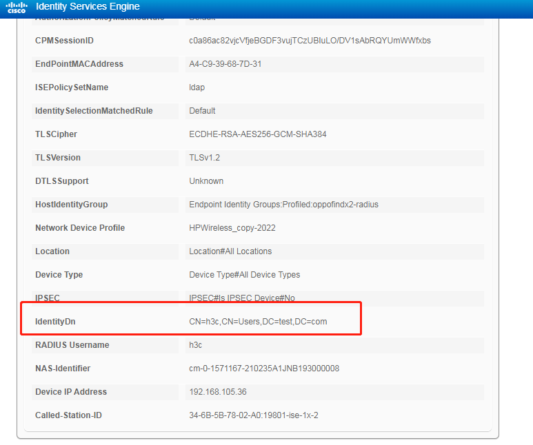
# On the ISE server, view authentication success logs to verify that the endpoint has passed authentication through the username and password stored on the LDAP server.
Figure 69 Viewing authentication success logs on the ISE server (1)
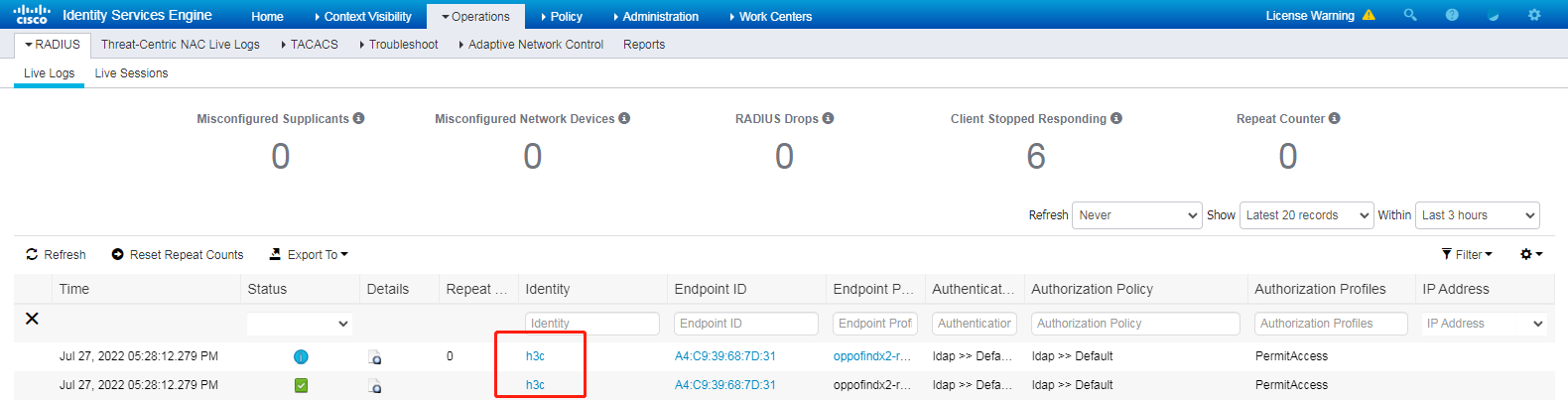
Figure 70 Viewing authentication success logs on the ISE server (2)
Configuration files
#
wlan service-template h3c-ise-ldap
ssid h3c-ise-ldap
akm mode dot1x
vlan 33
cipher-suite ccmp
security-ie rsn
client-security authentication-mode dot1x
dot1x domain ise
service-template enable
#
interface Vlan-interface1000
ip address 6.6.4.10 255.255.255.0
#
radius scheme ise
primary authentication 192.168.106.200 key simple 12345678
primary accounting 192.168.106.200 key simple 12345678
user-name-format without-domain
dot1x authentication-method eap
nas-ip 192.168.105.36
#
domain ise
authentication lan-access radius-scheme ise
authorization lan-access radius-scheme ise
accounting lan-access none
#
wlan ap ap1 model WA6622
serial-id 219801A23V8209E0043Y
radio 1
radio enable
service-template h3c-ise-ldap
radio 2
radio 3
#
