- Table of Contents
-
- H3C G6 Servers Storage Controller User Guide-6W100
- 00-Preface
- 01-Storage controller overview
- 02-Storage controller features
- 03-Configuring a VROC SATA RAID controller
- 04-Configuring an NVMe VROC module
- 05-Configuring an LSI-9540 or 9560 storage controller
- 06-Configuring a P460, P2404 or P4408 storage controller
- 07-Configuring an LSI 9500 series storage controller
- 08-Configuring a RAID-MARVELL-SANTACRUZ-LP-2i storage controller
- 09-Configuring a RAID-MARVELL-M.2 storage controller
- 10-Appendix A Troubleshooting storage controllers
- 11-Appendix B RAID arrays and fault tolerance
- Related Documents
-
| Title | Size | Download |
|---|---|---|
| 05-Configuring an LSI-9540 or 9560 storage controller | 11.57 MB |
Configuring an LSI-9540 or 9560 series storage controller
|
|
NOTE: The BIOS screens might vary by the BIOS version. The screenshots in this chapter are for illustration only. |
About LSI-9540 or 9560 series storage controllers
The storage controllers provide a maximum interface rate of 12 Gbps, and some storage controllers support caching, which greatly increases performance and data security. For more information about storage controller details and the supported cache, access http://www.h3c.com/en/home/qr/default.htm?id=66.
This chapter is applicable to the following storage controllers:
· RAID-LSI-9560-LP-16i-8GB
· RAID-LSI-9560-LP-8i-4GB
· HBA-LSI-9540-LP-8i
Features
RAID levels
The supported RAID levels vary by storage controller model. For more information about the supported RAID levels of each storage controller, contact Technical Support.
Table 1 shows the minimum number of drives required by each RAID level and the maximum number of failed drives supported by each RAID level. For more information about RAID levels, see "Appendix B RAID arrays and fault tolerance."
Table 1 RAID levels and the numbers of drives for each RAID level
|
RAID level |
Min. drives required |
Max. failed drives |
|
RAID 0 |
1 |
0 |
|
RAID 1 |
2 |
Number of drives divided by 2 |
|
RAID 5 |
3 |
1 |
|
RAID 6 |
For the LSI 9560: 4 For the other storage controllers: 3 (4 is recommended.) |
2 |
|
RAID 00 |
2 |
0 |
|
RAID 10 |
4 |
n, where n is the number of RAID 1 arrays in the RAID 10 array. |
|
RAID 50 |
6 |
n, where n is the number of RAID 5 arrays in the RAID 50 array. |
|
RAID 60 |
For the LSI 9560: 8 For the other storage controllers: 6 (8 is recommended.) |
2n, where n is the number of RAID 6 arrays in the RAID 60 array. |
|
|
NOTE: Storage controllers described in this chapter support using a maximum of eight member RAID 1/5/6 arrays to form a RAID 10/50/60 array. |
Restrictions and guidelines for configuring RAID
· As a best practice, configure RAID with drives that do not contain RAID information.
· To build a RAID successfully and ensure RAID performance, make sure all drives in the RAID are the same type (HDDs or SSDs) and have the same connector type (SAS or SATA).
· For efficient use of storage, use drives that have the same capacity to build a RAID. If the drives have different capacities, the lowest capacity is used across all drives in the RAID.
· If you use one physical drive to create multiple RAIDs, RAID performance might decrease in addition to increased maintenance complexities.
Configuring RAID arrays in UEFI mode
This section describes how to configure RAID arrays through a storage controller in UEFI mode. For more information about how to enter the BIOS and set the boot mode to UEFI, see the BIOS user guide for the server.
RAID array configuration tasks at a glance
To configure a RAID array in UEFI mode, perform the following tasks:
· Accessing the storage controller configuration screen
· (Optional.) Configuring hot spare drives
· (Optional.) Deleting a RAID array
· (Optional.) Locating drives
· (Optional.) Initializing a virtual drive
· (Optional.) Initializing a physical drive
· (Optional.) Erasing drives
· (Optional.) Expanding a RAID array
· (Optional.) Migrating the RAID level
· (Optional.) Clearing RAID array information on the drive
· (Optional.) Hiding a virtual drive
· (Optional.) Hiding a RAID array
· (Optional.) Upgrading the storage controller firmware online
· (Optional.) Switching the storage controller mode
· (Optional.) Forcing a logical drive to come online
· (Optional.) Adding new drives to a RAID array
· (Optional.) Viewing storage controller properties
· (Optional.) Importing foreign configuration
· (Optional.) Clearing foreign configuration
· (Optional.) Creating multiple virtual drives
Accessing the storage controller configuration screen
1. Access the BIOS. Press Delete, Esc, or F2 as prompted during server POST to open the BIOS setup screen as shown in Figure 1. For some devices, the Front Page screen opens, and you must select Device Management before proceeding to the next step.
For how to navigate screens and modify settings, see the operation instructions at the lower right corner.
Figure 1 BIOS setup screen

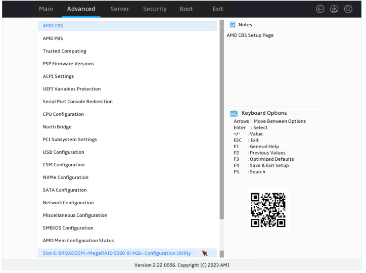
2. On the screen as shown in Figure 2, select Advanced > storage controller model, and press Enter.
In this example, the storage controller model is BROADCOM < MegaRAID 9560-8i 4GB>.
Figure 2 Advanced screen
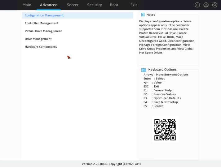
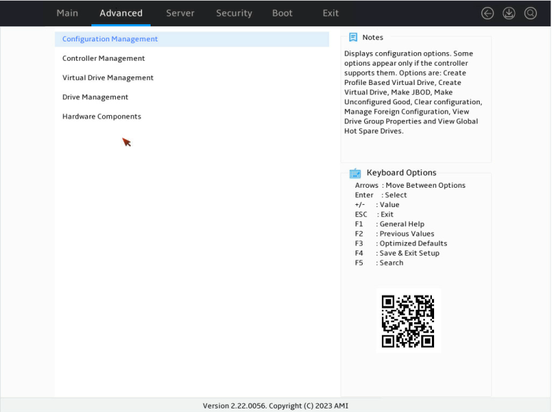
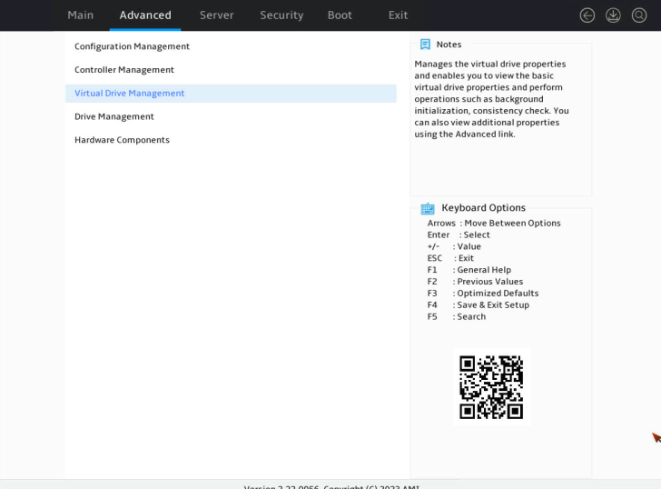
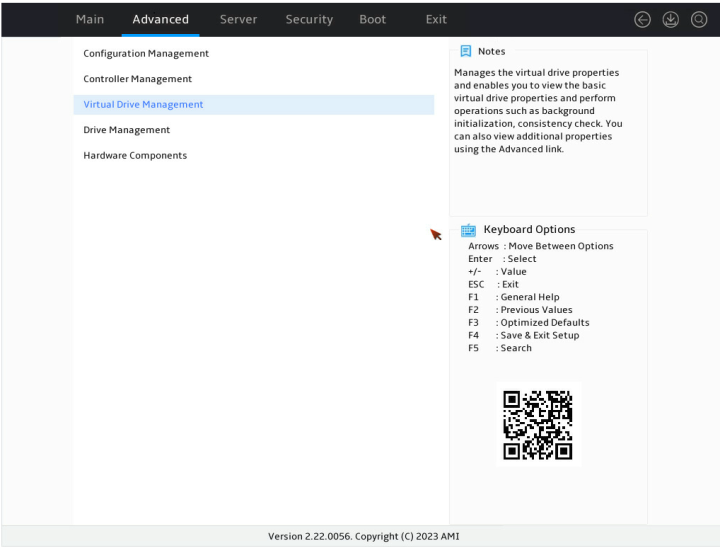
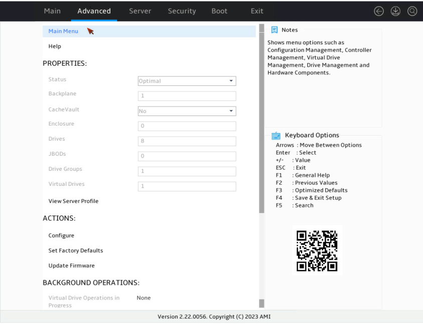
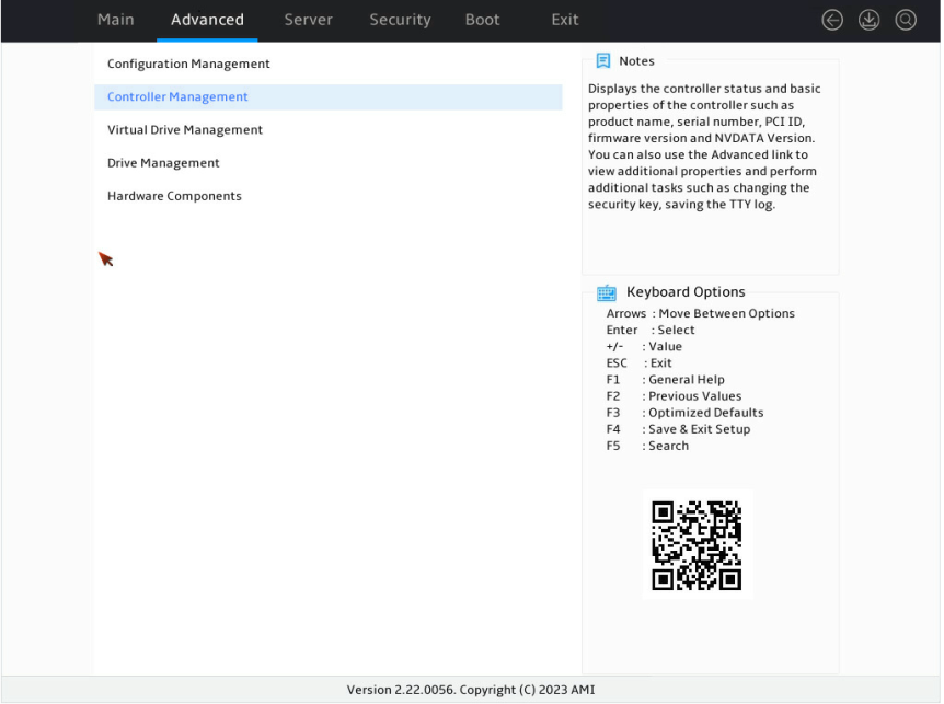
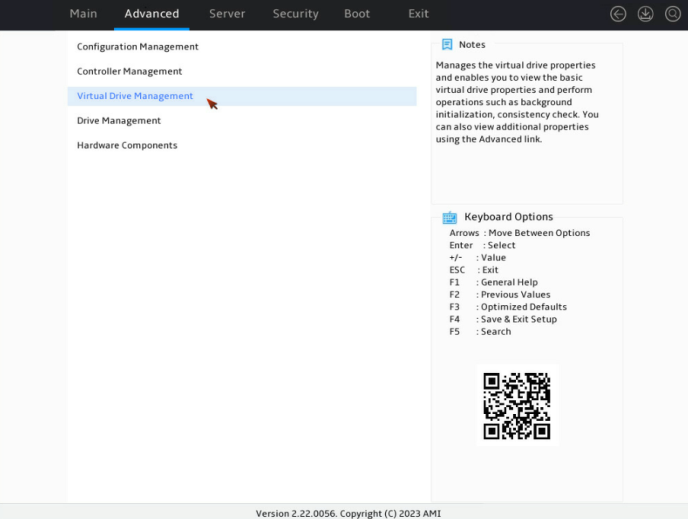
3. Select Main Menu as shown in Figure 3, and press Enter.

The storage controller configuration screen as shown in Figure 4 opens. This screen contains five tasks as described in Table 2.
Figure 4 Storage controller configuration screen
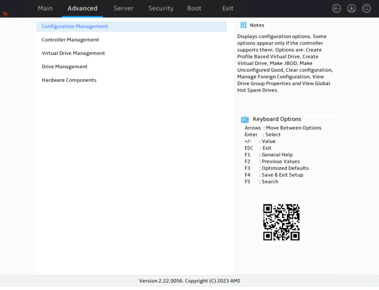
Table 2 Storage controller configuration tasks
|
Option |
Description |
|
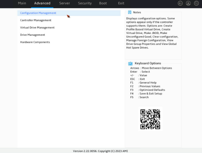
Configuration Management |
Select Configuration Management to perform the following tasks: · Create RAID arrays. · View RAID array properties. · View hot spare drives. · Clear configuration. |
|
Controller Management |
Select Controller Management to perform the following tasks: · View and manage controller properties. · Clear, schedule, or run controller events. |
|
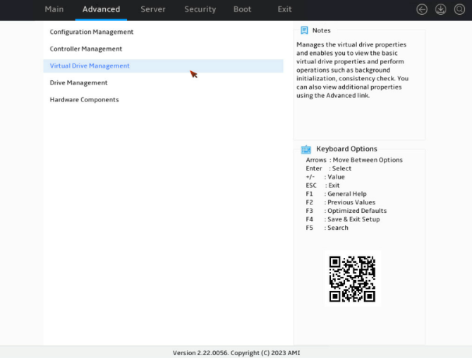
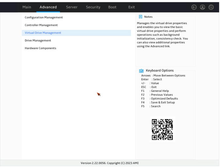
Virtual Drive Management |
Select Virtual Drive Management to perform the following tasks: · View logical drive properties. · Locate logical drives. · Run consistency check. |
|
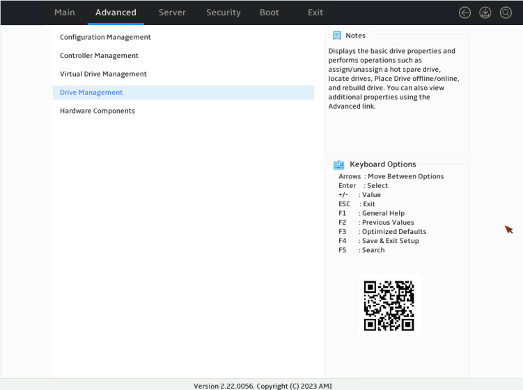
Drive Management |
Select Drive Management to perform the following tasks: · View physical drive properties. · Locate drives. · Initialize drives. · Rebuild drives. |
|
Hardware Components |
Select Hardware Components to perform the following tasks: · View supercapacitor properties. · Manage supercapacitor. · Manage peripheral components. |
Switching the drive state
The storage controller supports the following drive states:
· Unconfigured Good—The drive is normal and can be used for RAID array or hot backup configuration.
· Unconfigured Bad—The drive is faulty or has RAID array information remaining on it. If the drive is faulty, replace the drive. If RAID array information remains on the drive, clear the RAID array information.
· Hotspare—The drive is a hot spare drive.
· JBOD/JBOD online—Just a Bunch Of Disks. The drive is a passthrough or passthrough-like drive and does not support RAID configuration.
To switch from Unconfigured Good state to Unconfigured Bad state as an example:
1. On the storage controller configuration screen as shown in Figure 5, select Drive Management and press Enter.
Figure 5 Storage controller configuration screen
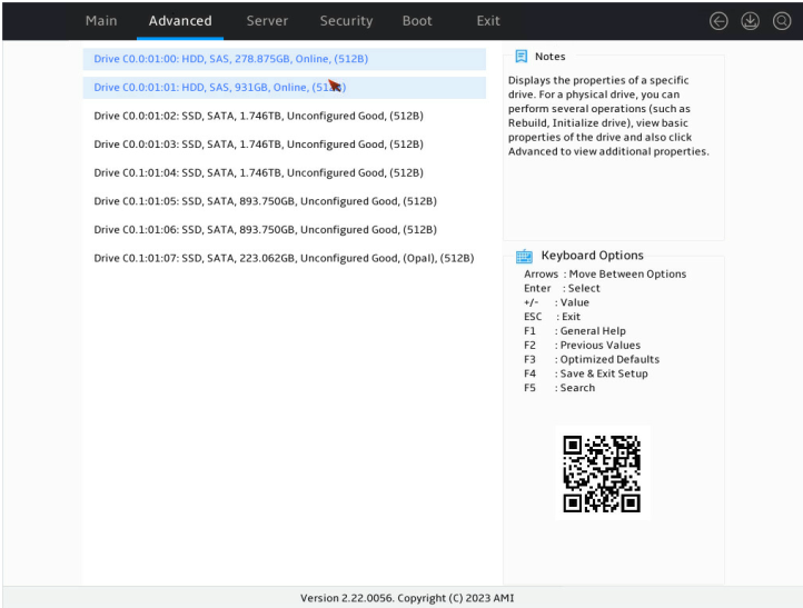
2. On the screen as shown in Figure 6, select the target drive and press Enter.
Figure 6 Drive Management screen
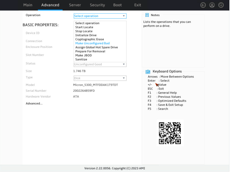
3. On the screen as shown in Figure 7, select Operation and press Enter. On the dialog box that appears, select Make Unconfigured Bad and press Enter.
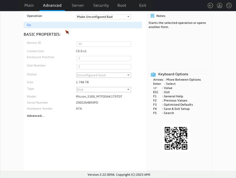
4. On the screen as shown in Figure 8, select Go and press Enter.
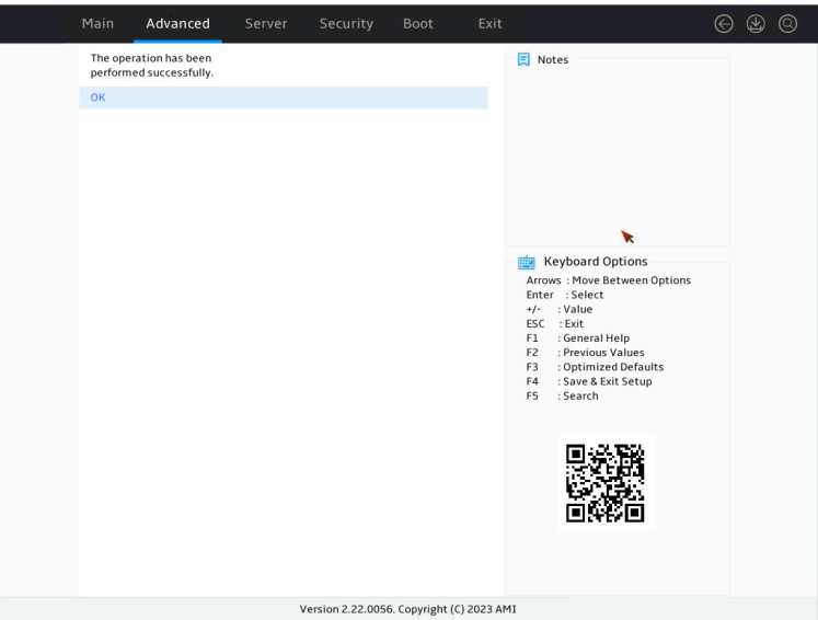
When the operation is complete, the screen as shown in Figure 9 opens.
Figure 9 Completing drive state switchover
Configuring RAID 0/1/5/6
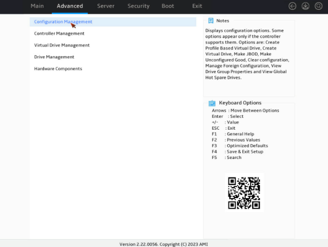
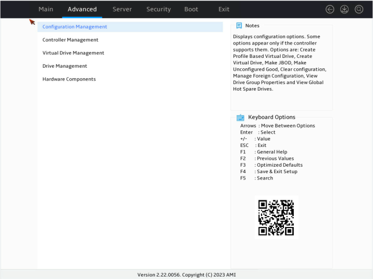
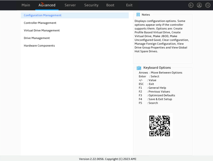
1. On the storage controller configuration screen as shown in Figure 10, select Configuration Management and press Enter.
Figure 10 Storage controller configuration screen
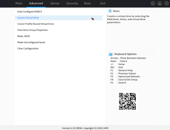
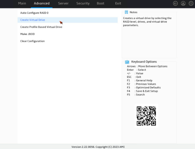
2. On the screen as shown in Figure 11, select Create Virtual Drive and press Enter.
Figure 11 Selecting Create Virtual Drive
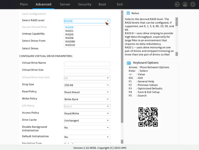
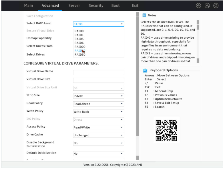
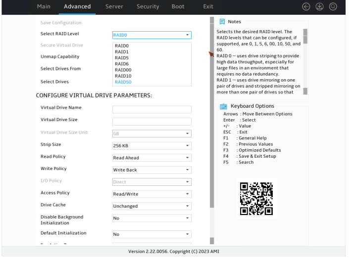
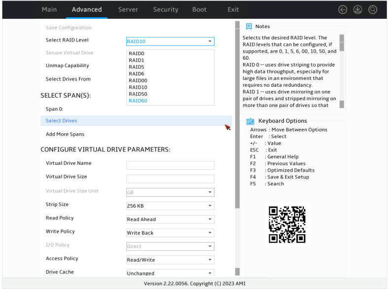
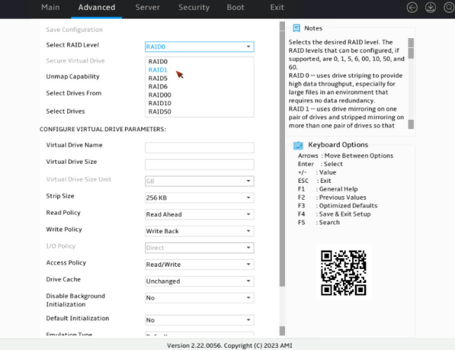
3. On the screen as shown in Figure 12, select Select RAID Level to set the RAID level, for example RAID 0, and then press Enter.
Figure 12 Setting the RAID level
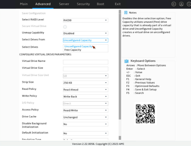
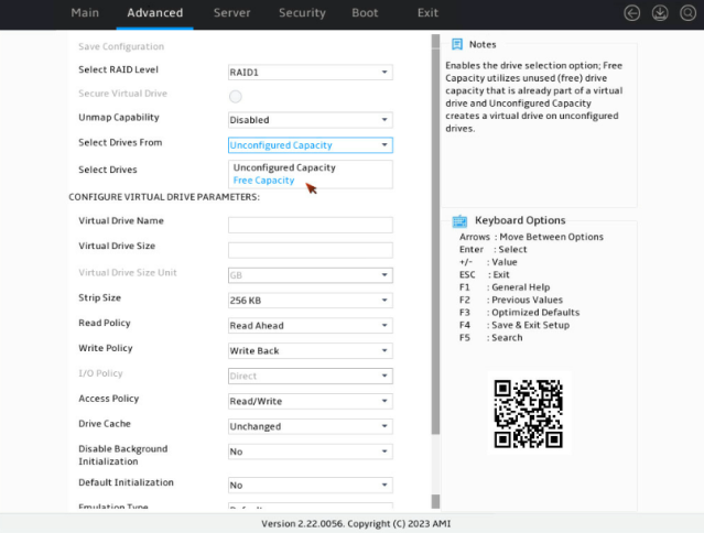
4. On the screen as shown in Figure 13, select Select Drives From to set the drive capacity source, and then press Enter.
¡ Unconfigured Capacity—The capacity source is the unconfigured drives. This example selects Unconfigured Capacity as an example.
¡ Free Capacity—The capacity source is the remaining drive capacity of the drives that have been used for RAID setup.
Figure 13 Setting the drive capacity source
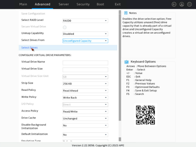
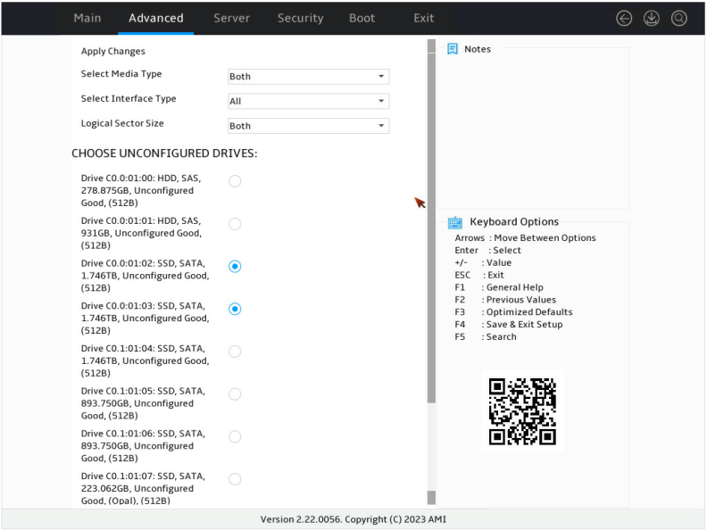
5. On the screen as shown in Figure 14, select Select Drives and press Enter.
Figure 14 Selecting Select Drives
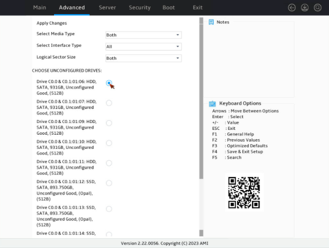
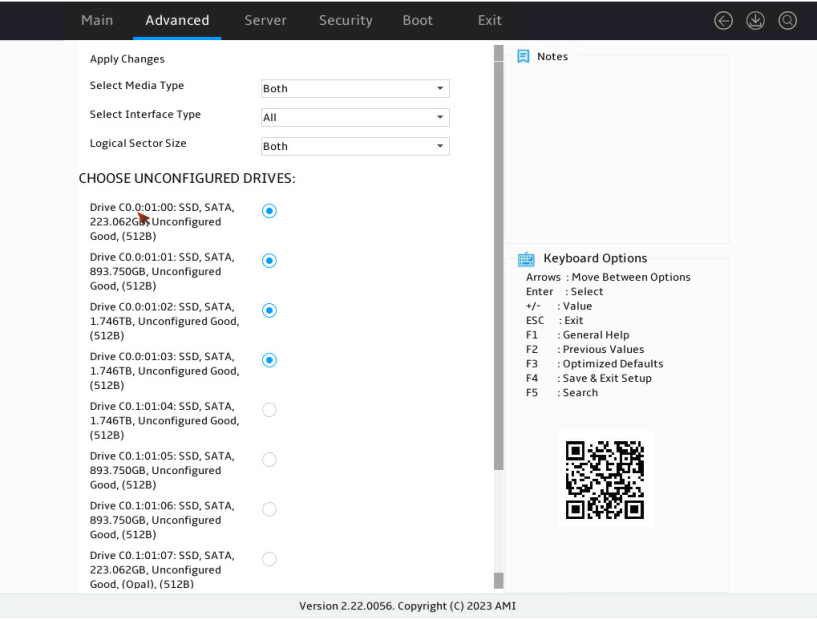
6. On the screen as shown in Figure 15, select the target drives and press Enter. Then, select Apply Changes and press Enter. A drive in JBOD, Unconfigured Bad, or Hotspare status cannot be selected.
Figure 15 Selecting the target drives
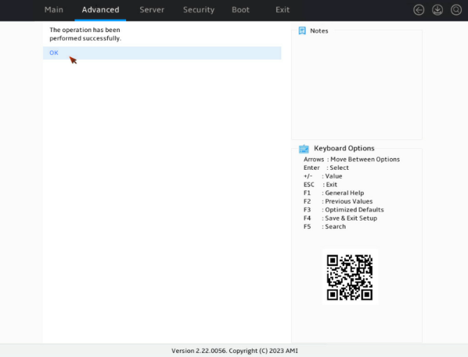
7. On the screen as shown in Figure 16, select OK and press Enter.
Figure 16 Completing selecting drives
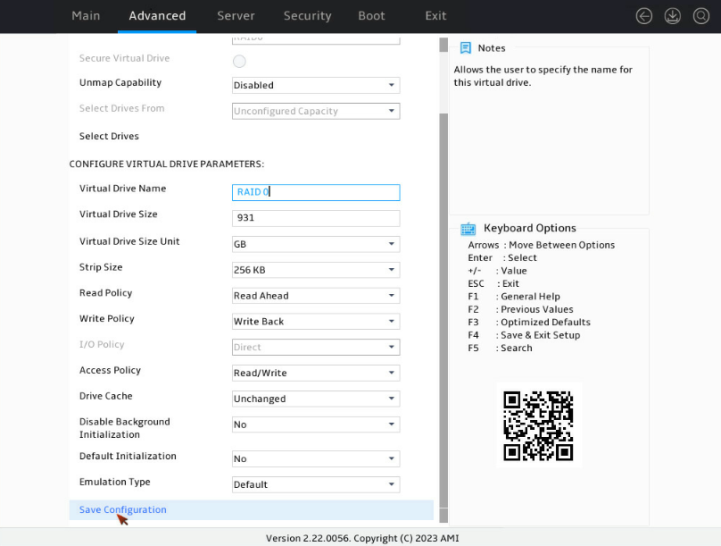
8. On the screen as shown in Figure 17, configure the parameters, select Save Configuration, and press Enter. For more information about the parameter description, see Table 3.
Figure 17 Configuring RAID parameters
|
Parameter |
Description |
|
Virtual Drive Name |
RAID array name, a case-insensitive string of letters, digits, and special characters. |
|
Virtual Drive Size |
Capacity for the RAID array. |
|
Virtual Drive Size Unit |
Capacity unit for the RAID array. |
|
Stripe Size |
Stripe size of the RAID array, that is, data block size for each drive, including 64KB, 128KB, 256KB, 512KB, and 1MB. The HBA-LSI-9540-LP-8i storage controller supports only 64KB in the current software version. |
|
Read Policy |
Read cache policy: · Read ahead—Enables read ahead capability. When this capability is enabled, the storage controller can pre-read sequential data or anticipate data to be requested and store the data in the cache · No read ahead—Disables read ahead capability. The HBA-LSI-9540-LP-8i storage controller does not support configuring a read cache policy in the current software version. |
|
Write Policy |
Write cache policy: · Write through—Enables the controller to send data transfer completion signal to the host when the physical drives have received all data in a transaction. · Write back—Enables the controller to send data transfer completion signal to the host when the controller cache receives all data in a transaction. If the supercapacitor is faulty or no supercapacitor is present, the Write through policy is used. · Always write back—Uses the Write back policy even if the supercapacitor of the storage controller is absent or faulty. If the server is powered off, the controller cache loses its data because of lack of power. |
|
Access Policy |
Read and write policy: · Read/Write · Read Only · Blocked |
|
I/O Policy |
I/O policy: · Direct—Enables the system to read or write data directly from or into a drive by read operations (excluding read ahead operations) or by write through operations of the storage controller. · Cached—Enables the cache module to process all read and write operations of the storage controller. Recommended only when CacheCade 1.1 is configured. The HBA-LSI-9540-LP-8i storage controller does not support configuring a I/O policy in the current software version. |
|
Drive Cache |
Drive cache policy: · Enable—Enables the controller to write data in the cache of physical drives during the write process to improve write performance. If this policy is used without a protection method in place, data will get lost upon an unexpected power failure. · Disable—Disables the controller from writing data in the cache of physical drives during the write process. If this policy is used, data will not get lost upon an unexpected power failure, but the write performance will not as high as when drive caching is enabled. · Unchanged—Uses the default drive cache policy. |
|
Disable Background Initialization |
Enabling status of background initialization. |
|
Default Initialization |
Default initialization mode: · NO. · Fast. · Full. |
|
Emulation Type |
Sector size reported to the OS: · Default—Displays 512e (4K) as the sector size as long as one 512e member drive exists, and displays 512n as the sector size if no 512e member drive exists. · Disable—Displays 512n as the sector size if no 512e member drive exists. · Force—Displays 512e (4K) as the sector size even if no 512e member drive exists. |
|
Save Configuration |
Select this option to save the configuration. |
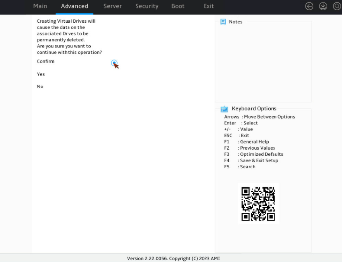
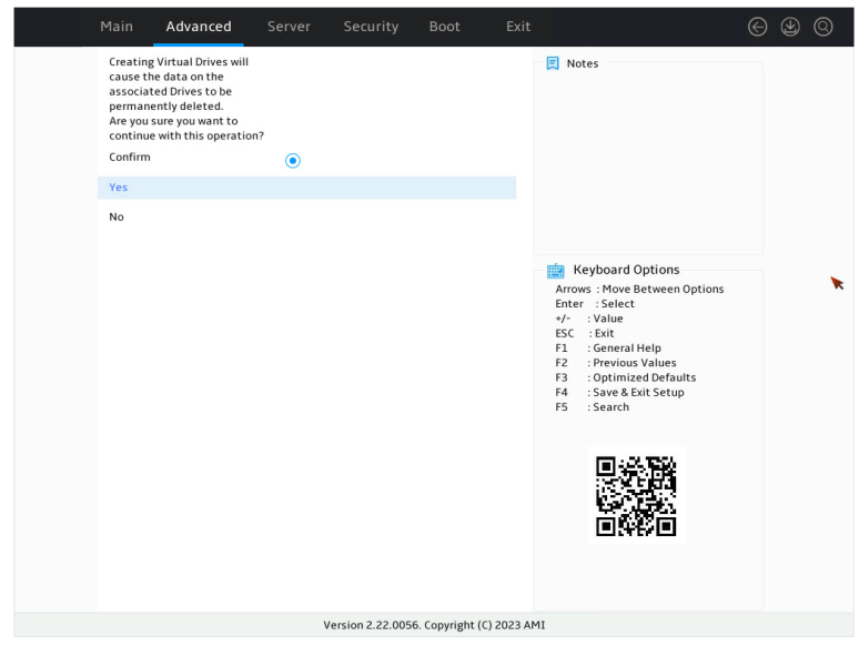
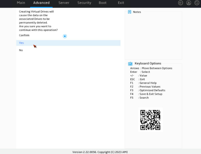
9. On the screen as shown in Figure 18, select Confirm. Then, select Yes and press Enter.
Figure 18 Confirming the operation
10. On the screen as shown in Figure 19, select OK to return to the storage controller configuration screen.
Figure 19 Completing RAID array configuration

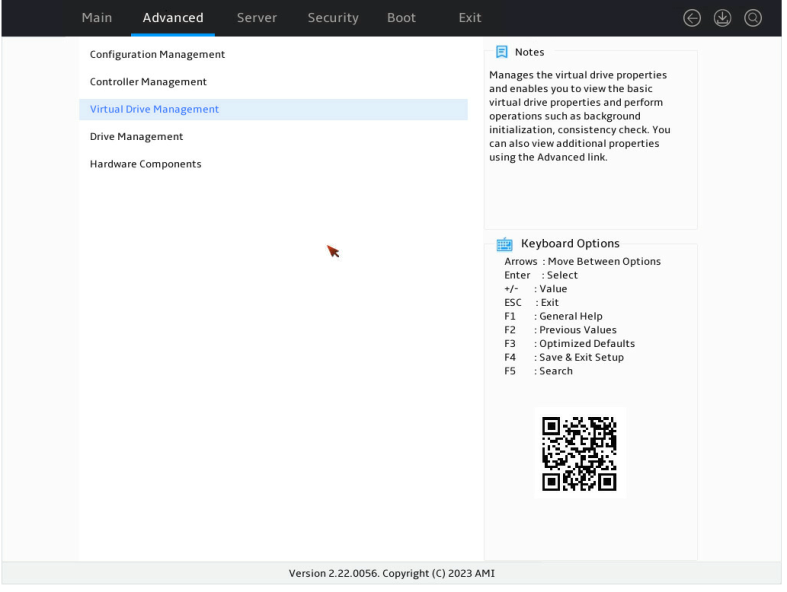
11. Select Virtual Drive Management and press Enter as shown in Figure 20.
Figure 20 Storage controller configuration screen
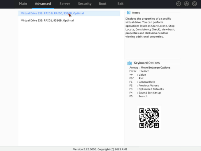
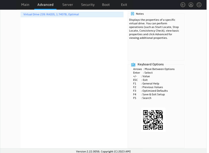
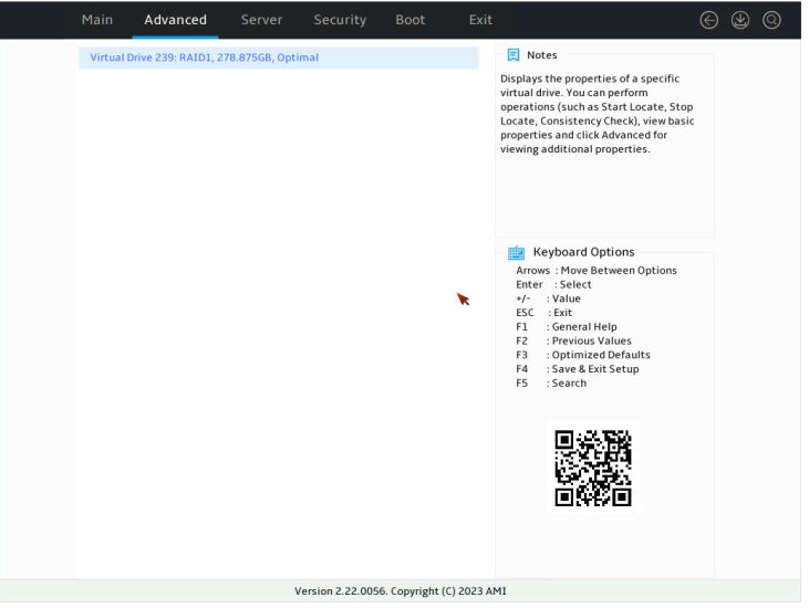
12. On the screen as shown in Figure 21, you can see the created drives. Select the drive you want to view and press Enter.
Figure 21 Virtual Drive Management screen
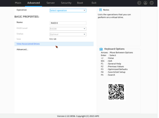
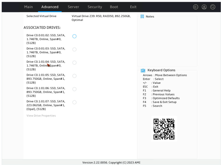
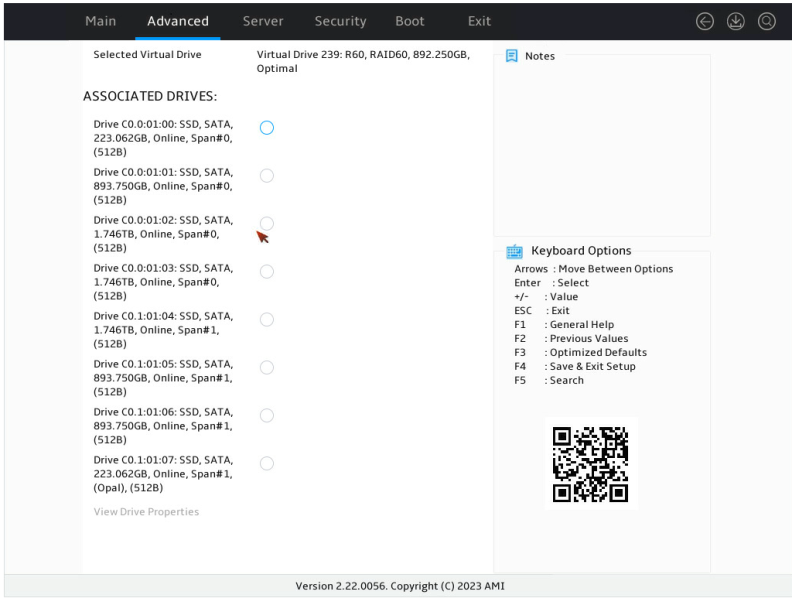
13. On the screen as shown in Figure 22, select View Associated Drives and press Enter. You can view the detailed information about the RAID array, including name, level, and drive information.
Figure 22 Selecting View Associated Drives
Configuring RAID 10
1. On the storage controller configuration screen as shown in Figure 23, select Configuration Management and press Enter.
Figure 23 Storage controller configuration screen

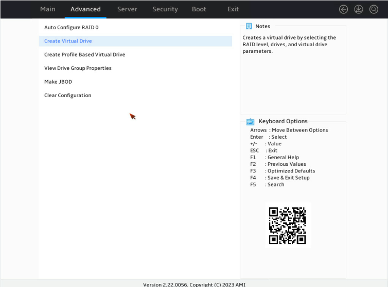
2. On the screen as shown in Figure 24, select Create Virtual Drive and press Enter.
Figure 24 Selecting Create Virtual Drive

3. On the screen as shown in Figure 25, select Select RAID Level to set the RAID level, and then press Enter.
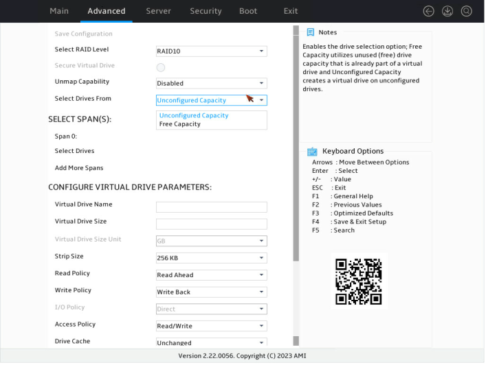
4. On the screen as shown in Figure 26, select Select Drives From to set the drive capacity source, and then press Enter.
Figure 26 Setting the drive capacity source

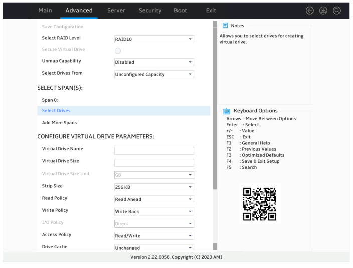
5. On the screen as shown in Figure 27, select Select Drives and press Enter.
Figure 27 Selecting Select Drives

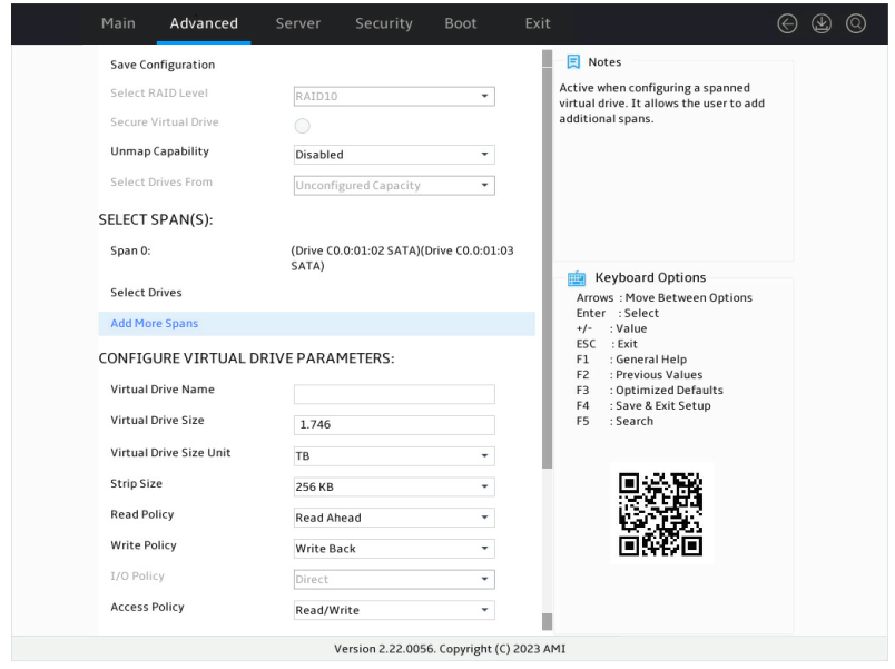
6. On the screen as shown in Figure 28, select the target drives. ([Enabled] following a drive means that the drive has been selected.) Then, select Apply Changes and press Enter.
Figure 28 Selecting the target drives
7. On the screen as shown in Figure 29, select Add More Spans and press Enter to add drive space. A minimum of four drives are required for setting up RAID10.
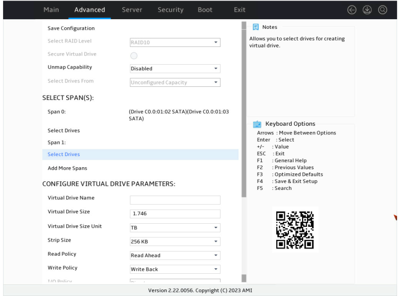
8. On the screen as shown in Figure 30, select Select Drives and press Enter.
Figure 30 Selecting Select Drives
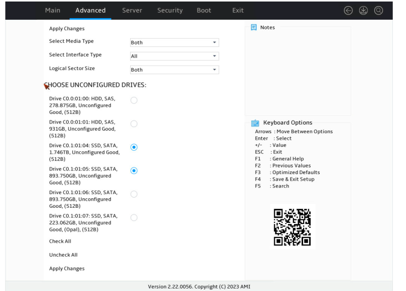
9. On the screen as shown in Figure 31, select the target drives. ([Enabled] following a drive means that the drive has been selected.) Then, select Apply Changes and press Enter. A drive in JBOD or Unconfigured Bad status cannot be selected.
Figure 31 Selecting the target drives
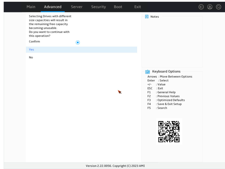
10. On the screen as shown in Figure 32, select Confirm. Then, select Yes and press Enter.
Figure 32 Confirming the operation
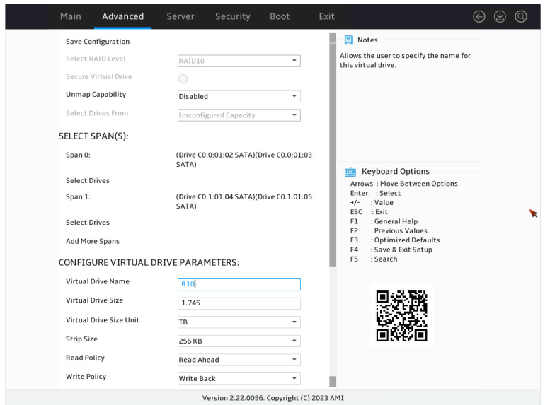
11. On the screen as shown in Figure 33, configure the parameters, select Save Configuration, and press Enter. For more information about the parameter description, see Table 3.
Figure 33 Configuring RAID parameters
12. On the screen as shown in Figure 34, select Confirm. Then, select Yes and press Enter.
Figure 34 Confirming the operation

13. On the screen as shown in Figure 35, select OK to return to the storage controller configuration screen.
Figure 35 Completing RAID array configuration

14. As shown in Figure 36, on the storage controller configuration screen, select Virtual Drive Management and press Enter.
Figure 36 Storage controller configuration screen

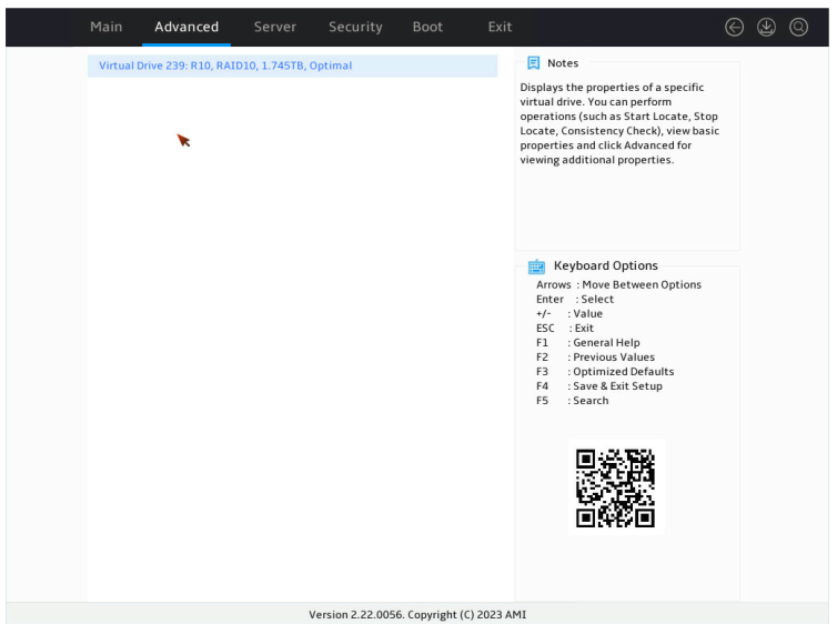
15. On the screen as shown in Figure 37, you can see the created RAID arrays. Select RAID10 you want to view and press Enter.
Figure 37 Virtual Drive Management screen
16. On the screen as shown in Figure 38, select View Associated Drives and press Enter. You can view the detailed information about the RAID array, including name, level, and drive information.
Figure 38 Selecting View Associated Drives

Configuring RAID 50
1. On the storage controller configuration screen as shown in Figure 39, select Configuration Management and press Enter.
Figure 39 Storage controller configuration screen

2. On the screen as shown in Figure 40, select Create Virtual Drive and press Enter.
Figure 40 Selecting Create Virtual Drive
3. On the screen as shown in Figure 41, select Select RAID Level to set the RAID level, and then press Enter.
Figure 41 Setting the RAID level
4. On the screen as shown in Figure 42, select Select Drives From to set the drive capacity source, and then press Enter.
Figure 42 Setting the drive capacity source
5. On the screen as shown in Figure 43, select Select Drives and press Enter.
Figure 43 Selecting Select Drives
6. On the screen as shown in Figure 44, select the target drives. ([Enabled] following a drive means that the drive has been selected.) Then, select Apply Changes and press Enter.
Figure 44 Selecting the target drives

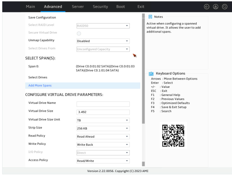
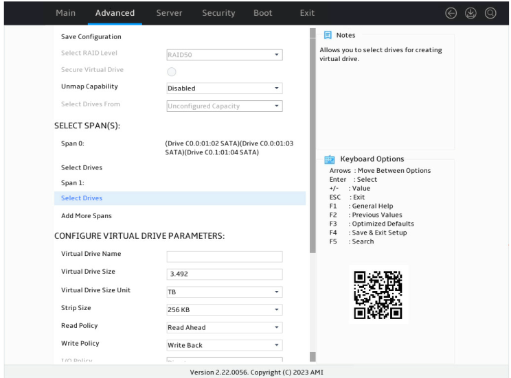
7. On the screen as shown in Figure 45, select Add More Spans and press Enter to add drive space. A minimum of six drives are required for setting up RAID50.
8. On the screen as shown in Figure 46, select Select Drives and press Enter.
Figure 46 Selecting Select Drives
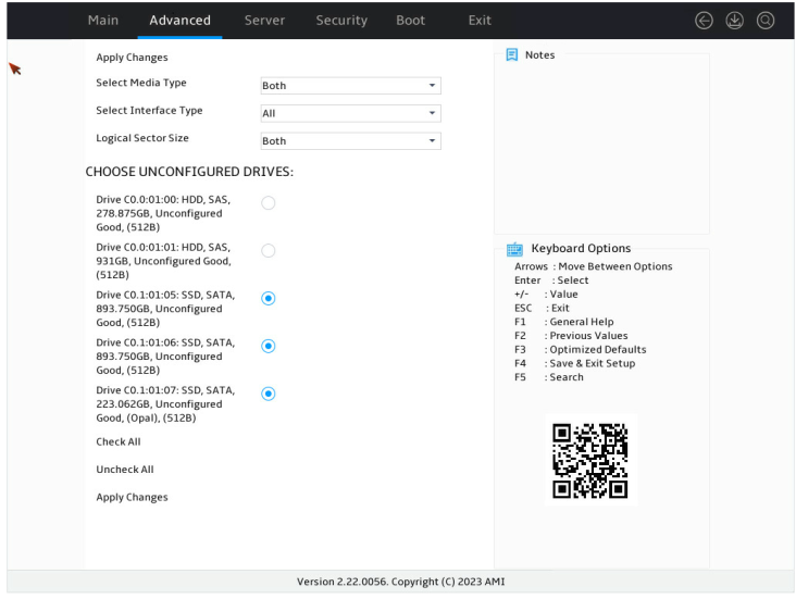
9. On the screen as shown in Figure 47, select the target drives. ([Enabled] following a drive means that the drive has been selected.) Then, select Apply Changes and press Enter. A drive in JBOD or Unconfigured Bad status cannot be selected.
Figure 47 Selecting the target drives
10. On the screen as shown in Figure 48, select Confirm. Then, select Yes and press Enter.
Figure 48 Confirming the operation

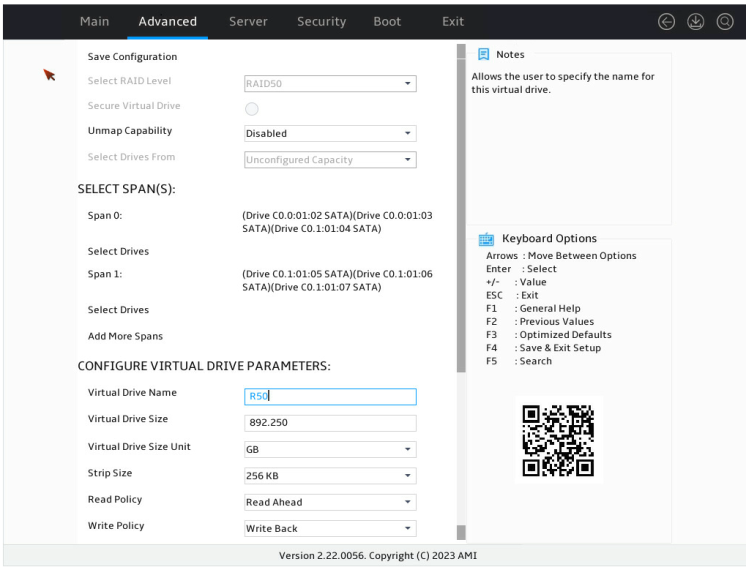
11. On the screen as shown in Figure 49, configure the parameters, select Save Configuration, and press Enter. For more information about the parameter description, see Table 3.
Figure 49 Configuring RAID parameters
12. On the screen as shown in Figure 50, select Confirm. Then, select Yes and press Enter.
Figure 50 Confirming the operation

13. On the screen as shown in Figure 51, select OK to return to the storage controller configuration screen.
Figure 51 Completing RAID array configuration
14. On the storage controller configuration screen as shown in Figure 52, select Virtual Drive Management and press Enter.
Figure 52 Storage controller configuration screen

15. On the screen as shown in Figure 53, you can see the created RAID arrays. Select RAID50 you want to view and press Enter.
Figure 53 Virtual Drive Management screen

16. On the screen as shown in Figure 54, select View Associated Drives and press Enter. You can view the detailed information about the RAID array, including name, level, and drive information.
Figure 54 Selecting View Associated Drives
Configuring RAID 60
1. On the storage controller configuration screen as shown in Figure 55, select Configuration Management and press Enter.
Figure 55 Storage controller configuration screen
2. On the screen as shown in Figure 56, select Create Virtual Drive and press Enter.
Figure 56 Selecting Create Virtual Drive

3. On the screen as shown in Figure 57, select Select RAID Level to set the RAID level, and then press Enter.
Figure 57 Settings the RAID level
4. On the screen as shown in Figure 58, select Select Drives From to set the drive capacity source, and then press Enter.
Figure 58 Setting the drive capacity source

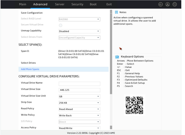
5. On the screen as shown in Figure 59, select Select Drives and press Enter.
Figure 59 Selecting Select Drives

6. On the screen as shown in Figure 60, select the target drives. ([Enabled] following a drive means that the drive has been selected.) Then, select Apply Changes and press Enter.
Figure 60 Selecting the target drives
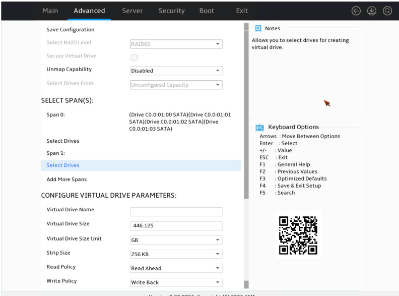
7. On the screen as shown in Figure 61, select Add More Spans and press Enter to add drive space. A minimum of eight drives are required for setting up RAID60.
8. On the screen as shown in Figure 62, select Select Drives and press Enter.
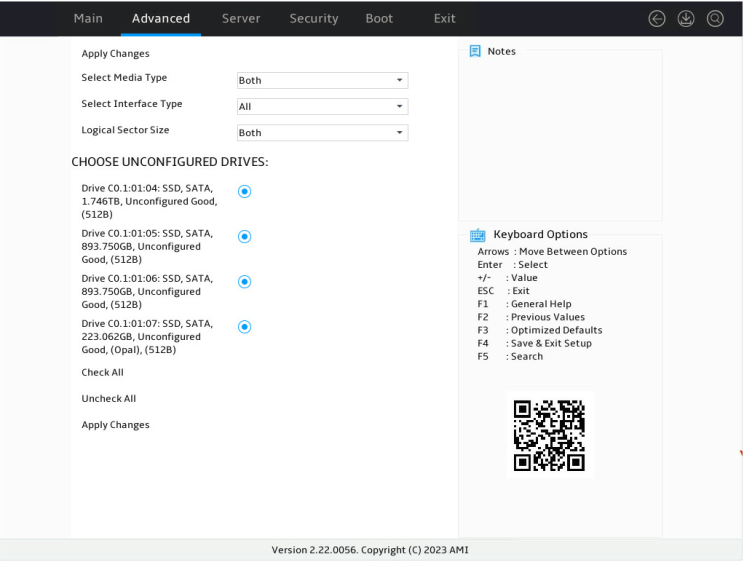
Figure 62 Selecting Select Drives
9. On the screen as shown in Figure 63, select the target drives. ([Enabled] following a drive means that the drive has been selected.) Then, select Apply Changes and press Enter. A drive in JBOD or Unconfigured Bad status cannot be selected.
Figure 63 Selecting the target drives
10. On the screen as shown in Figure 64, select Confirm. Then, select Yes and press Enter.
Figure 64 Confirming the operation

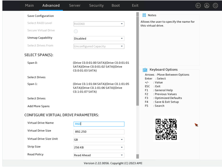
11. On the screen as shown in Figure 65, configure the parameters, select Save Configuration, and press Enter. For more information about the parameter description, see Table 3.
Figure 65 Configuring RAID parameters
12. On the screen as shown in Figure 66, select Confirm. Then, select Yes and press Enter.
Figure 66 Confirming the operation
13. On the screen as shown in Figure 67, select OK to return to the storage controller configuration screen.
Figure 67 Completing RAID array configuration

14. On the storage controller configuration screen as shown in Figure 68, select Virtual Drive Management and press Enter.
Figure 68 Storage controller configuration screen
15. On the screen as shown in Figure 69, you can see the created RAID arrays. Select RAID60 you want to view and press Enter.
Figure 69 Virtual Drive Management screen

16. On the screen as shown in Figure 70, select View Associated Drives and press Enter. You can view the detailed information about the RAID array, including name, level, and drive information.
Figure 70 Selecting View Associated Drives
Configuring hot spare drives
For data security purposes, configure hot spare drives after configuring a RAID array. You can configure global hot spare drives or dedicated hot spare drives.
|
|
NOTE: · A hot spare drive can be used only for RAID levels with redundancy. · The capacity of a hot spare drive must be equal to or greater than the capacity of the smallest drive in the RAID array. · Only the drive in Unconfigured Good state can be configured as a hot spare drive. |
Configuring a global hot spare drive
1. On the storage controller configuration screen as shown in Figure 71, select Drive Management and press Enter.
Figure 71 Storage controller configuration screen
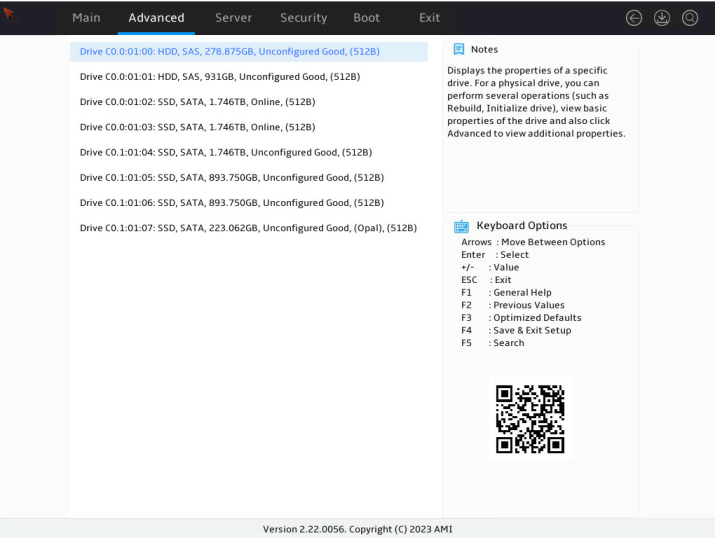
2. On the screen as shown in Figure 72, select the target drive and press Enter.
Figure 72 Drive Management screen
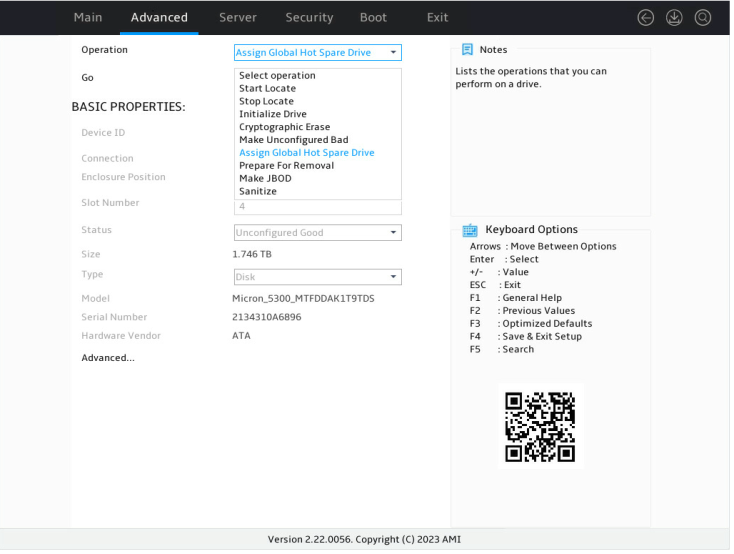
3. On the screen as shown in Figure 73, select Operation and press Enter. On the dialog box that appears, select Assign Global Hot Spare Drive and press Enter.
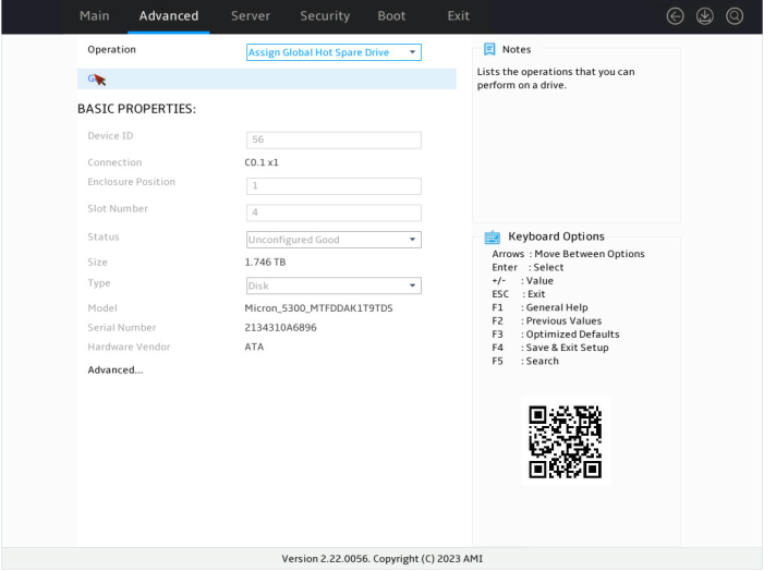
4. On the screen as shown in Figure 74, select Go and press Enter.
5. On the screen as shown in Figure 75, select Confirm. Then, select Yes and press Enter.
Figure 75 Confirming the operation
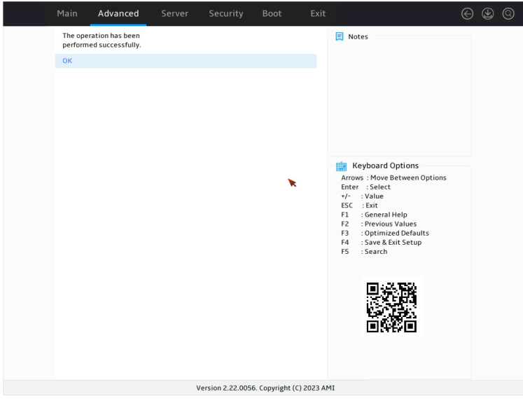
When the operation is complete, the screen as shown in Figure 76 opens.
Figure 76 Completing global hot spare drive configuration
Configuring a dedicated hot spare drive
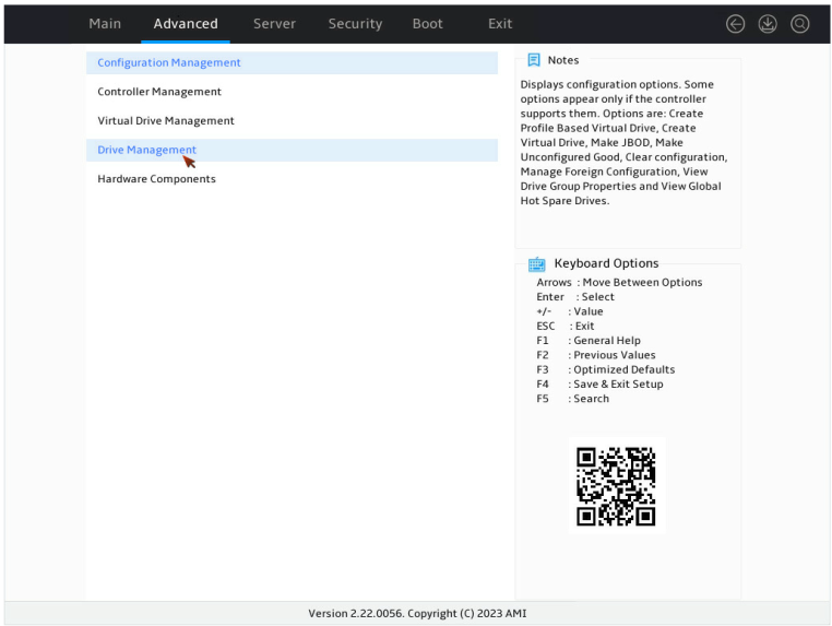
1. On the storage controller configuration screen as shown in Figure 77, select Drive Management and press Enter.
Figure 77 Storage controller configuration screen
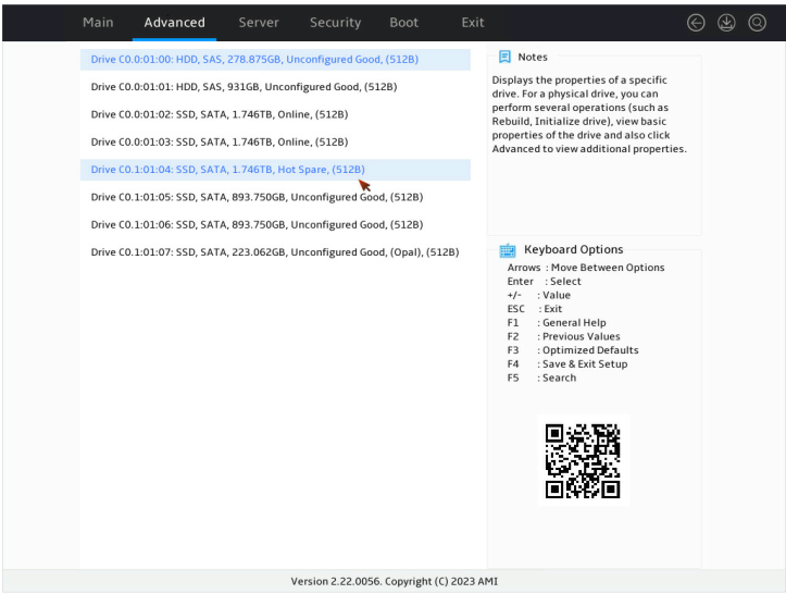
2. On the screen as shown in Figure 78, select the target drive and press Enter.
Figure 78 Drive Management screen

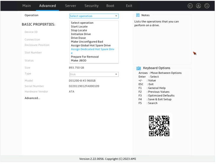
3. On the screen as shown in Figure 79, select Operation and press Enter. On the dialog box that appears, select Assign Dedicated Hot Spare Drive and press Enter.
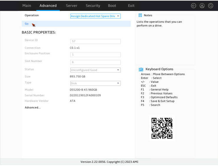
4. On the screen as shown in Figure 80, select Go and press Enter.
5. On the screen as shown in Figure 81, select the drive you want to configure as the hot spare drive. ([Enabled] following the drive means that the drive has been selected.) Then, select OK and press Enter.
Figure 81 Confirming selection
When the operation is complete, the screen as shown in Figure 82 opens.
Figure 82 Completing the operation
Deleting a RAID array
1. On the storage controller configuration screen as shown in Figure 83, select Virtual Drive Management and press Enter.
Figure 83 Storage controller configuration screen
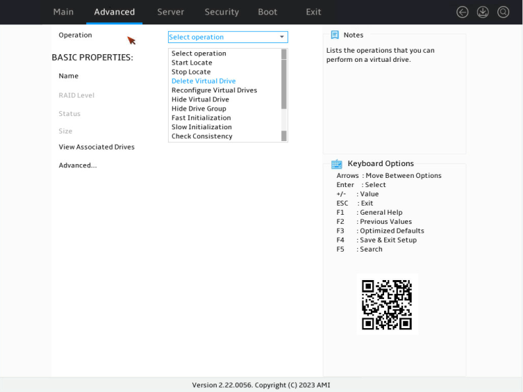
2. On the screen as shown in Figure 84, select the target virtual drive and press Enter.
Figure 84 Virtual Drive Management screen
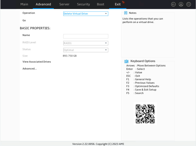
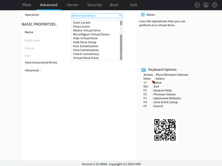
3. On the screen as shown in Figure 85, select Operation and press Enter. On the dialog box that appears, select Delete Virtual Drive and press Enter.
4. On the screen as shown in Figure 86, select Go and press Enter.
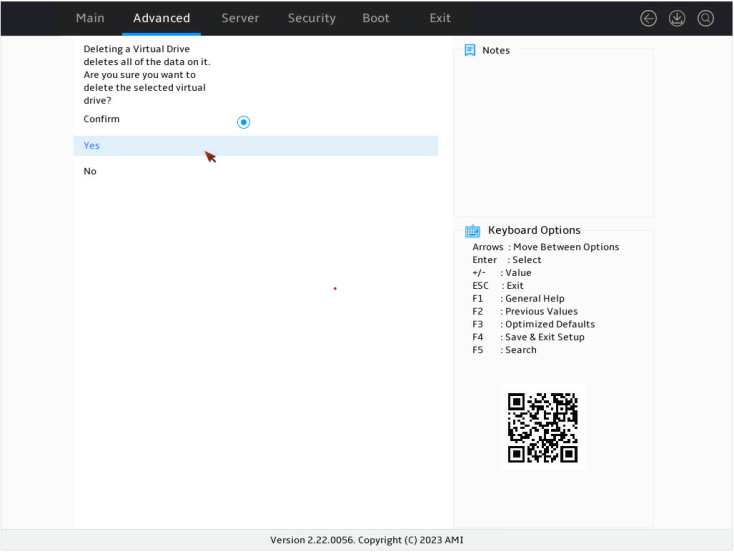
5. On the screen as shown in Figure 87, select Confirm. Then, select Yes and press Enter.
Figure 87 Confirming the deletion
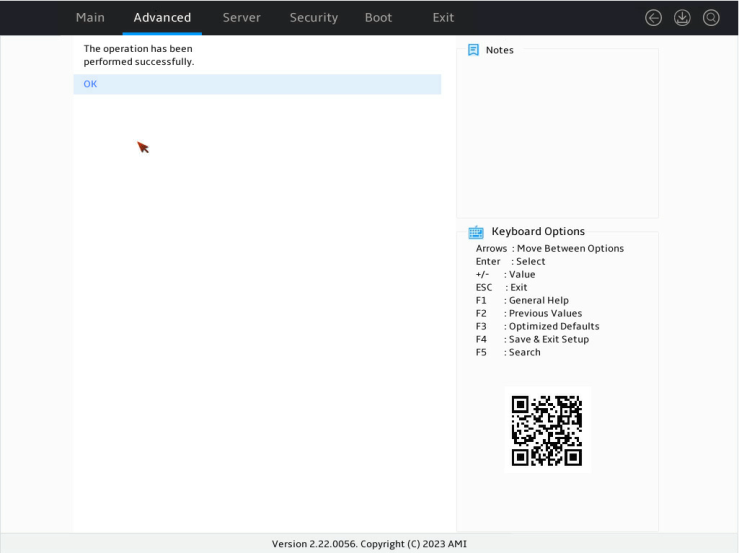
When the operation is complete, the screen as shown in Figure 88 opens.
Figure 88 Completing the operation
Locating drives
This task allows you to locate a physical drive or all drives for a virtual drive.
Locating a physical drive
1. On the storage controller configuration screen as shown in Figure 89, select Drive Management and press Enter.
Figure 89 Storage controller configuration screen

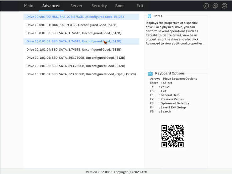
2. On the screen as shown in Figure 90, select the target drive and press Enter.
Figure 90 Selecting the target drive
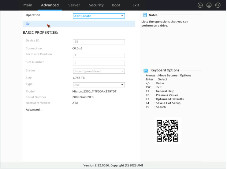
3. On the screen as shown in Figure 91, select Operation and press Enter. On the dialog box that opens, select Start Locate and press Enter.

4. On the screen as shown in Figure 92, select Go and press Enter.
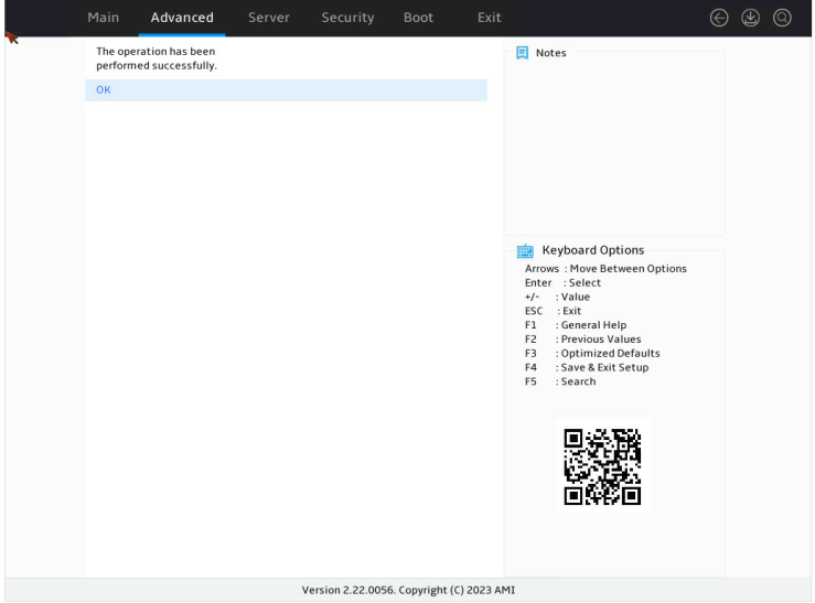
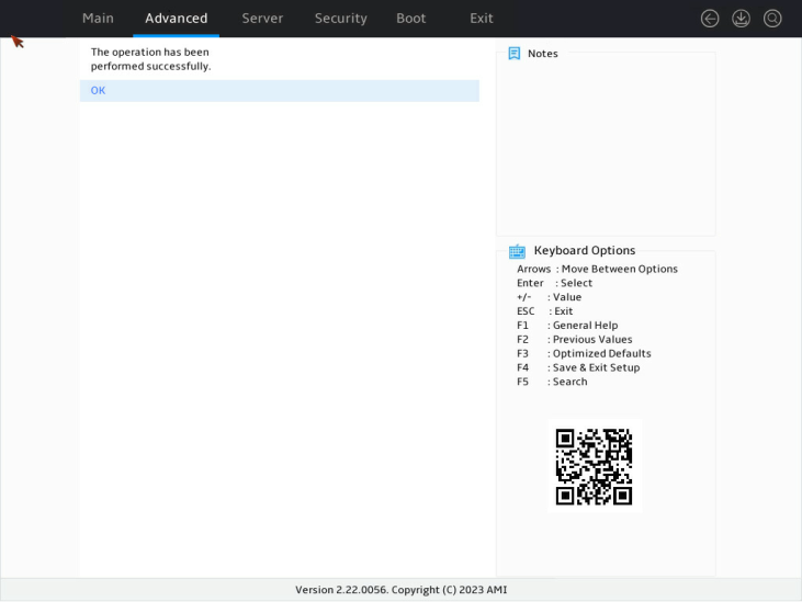
When the operation is complete, the screen as shown in Figure 93 opens. The Fault/UID LED on the drive turns steady blue.
Figure 93 Completing locating the physical drive
Locating all drives for a virtual drive
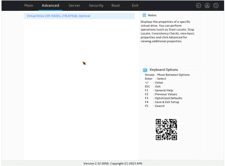
1. On the storage controller configuration screen as shown in Figure 94, select Virtual Drive Management and press Enter.
Figure 94 Storage controller configuration screen

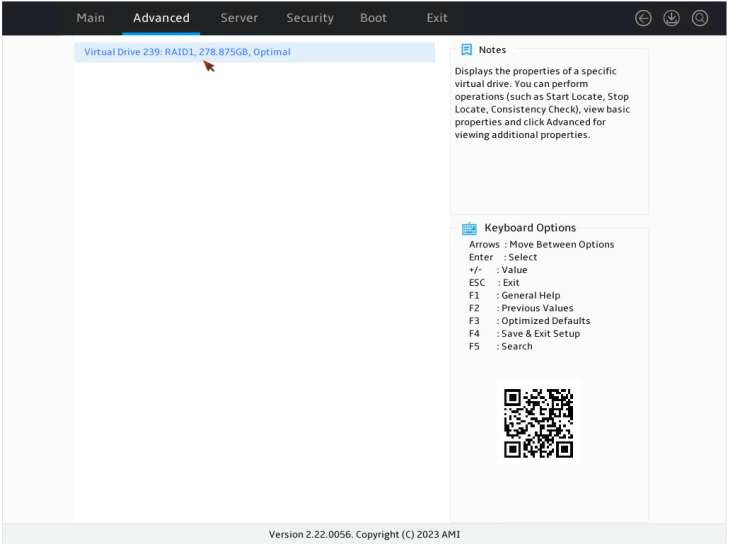
2. On the screen as shown in Figure 95, select the target drive and press Enter.
Figure 95 Selecting the target drive
3. On the screen as shown in Figure 96, select Operation and press Enter. On the dialog box that opens, select Start Locate and press Enter.
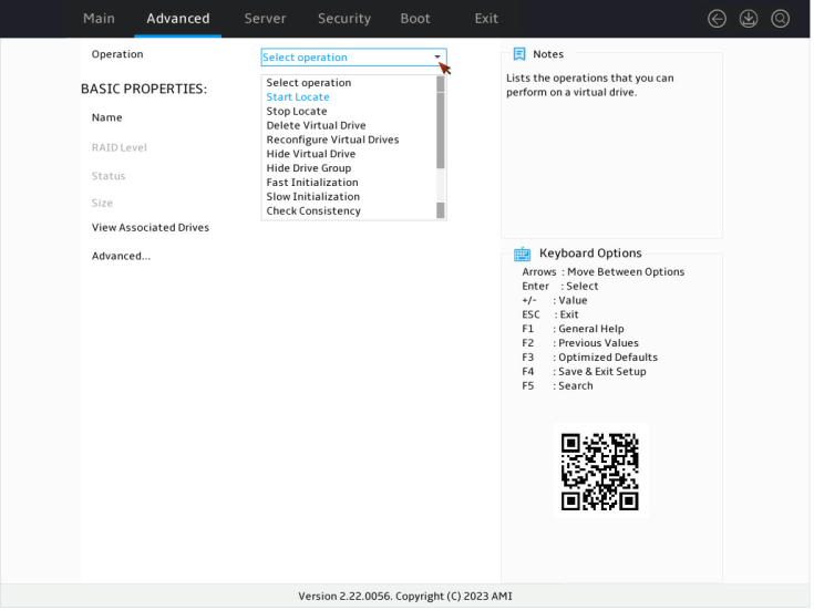
4. On the screen as shown in Figure 97, select Go and press Enter.

When the operation is complete, the screen as shown in Figure 98 opens. The Fault/UID LED on the drive turns steady blue.
Figure 98 Completing locating all drives for a virtual drive
Initializing a virtual drive
This task allows you to initialize a virtual drive to be used by operating systems.
To initialize a virtual drive:
1. On the storage controller configuration screen as shown in Figure 99, select Virtual Drive Management and press Enter.
Figure 99 Storage controller configuration screen
2. On the screen as shown in Figure 100, select the target drive and press Enter.
Figure 100 Virtual Drive Management screen
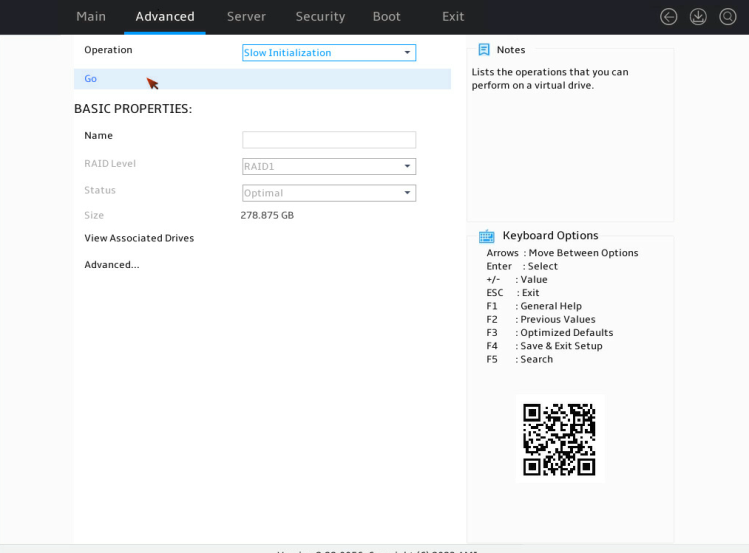
3. On the screen as shown in Figure 101, select Operation and press Enter. On the dialog box that appears, select Fast Initialization or Slow Initialization and press Enter.

|
|
NOTE: Fast initialization allows immediately writing data. Slow initialization allows writing data after initialization is complete. |
4. On the screen as shown in Figure 102, select Go and press Enter.
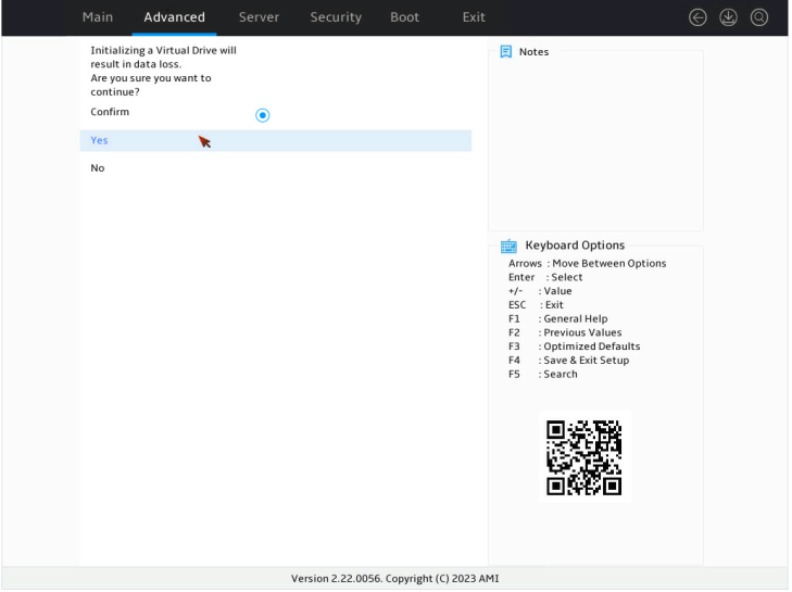
5. On the screen as shown in Figure 103, select Confirm. Then, select Yes and press Enter.
Figure 103 Confirming the initialization
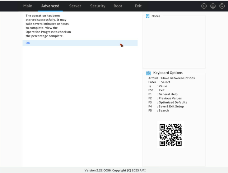
When the operation is complete, the screen as shown in Figure 104 opens.
Figure 104 Completing the operation
Initializing a physical drive
1. On the storage controller configuration screen as shown in Figure 105, select Drive Management and press Enter.
Figure 105 Storage controller configuration screen
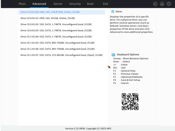
2. On the screen as shown in Figure 106, select the target drive and press Enter.
Figure 106 Drive Management screen
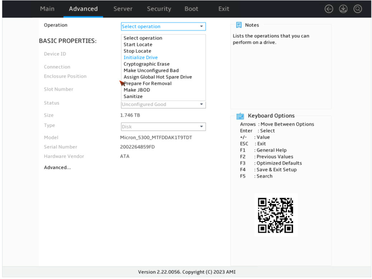
3. On the screen as shown in Figure 107, select Operation and press Enter. On the dialog box that opens, select Initialize Drive and press Enter.
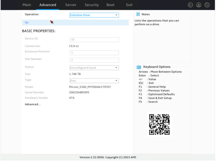
4. On the screen as shown in Figure 108, select Go and press Enter.
5. On the screen as shown in Figure 109, select Confirm. Then, select Yes and press Enter.
Figure 109 Confirming the initialization

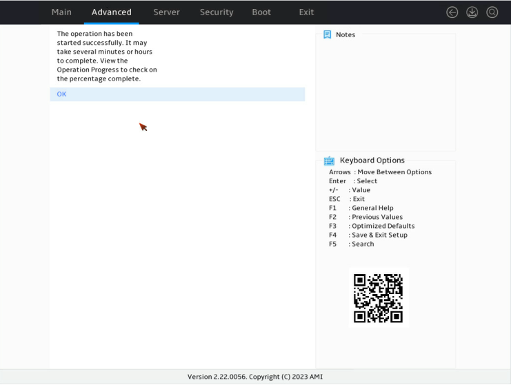
When the operation is complete, the screen as shown in Figure 110 opens.
Figure 110 Completing the operation
Erasing drives
|
|
CAUTION: To avoid drive failure, do not perform other operations when erasing a physical drive. |
This task allows you to erase data from physical and logical drives.
Erasing a physical drive
1. On the storage controller configuration screen as shown in Figure 111, select Drive Management and press Enter.
Figure 111 Storage controller configuration screen

2. On the screen as shown in Figure 112, select the target drive and press Enter.
Figure 112 Drive Management screen

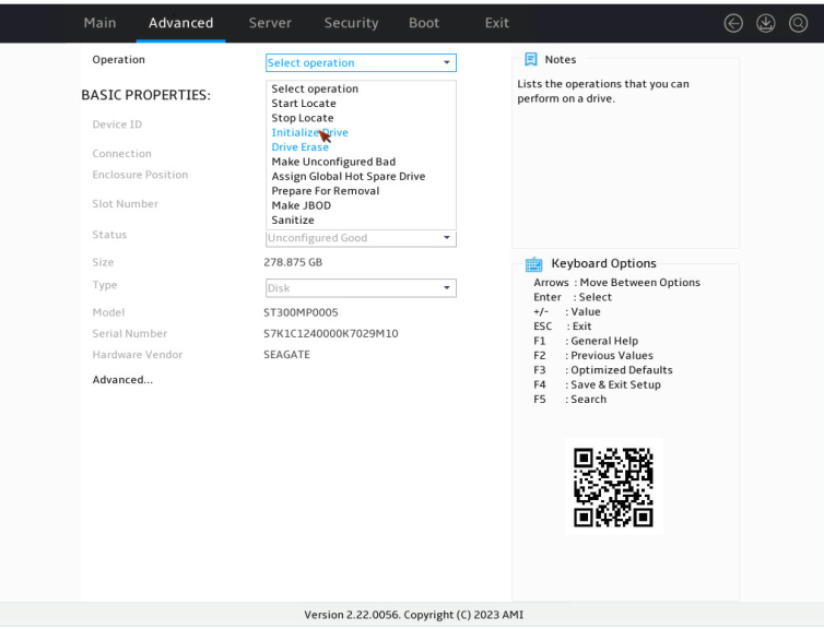
3. On the screen as shown in Figure 113, select Operation and press Enter.
4. On the dialog box that opens, select Drive Erase and press Enter.
For some controllers, you must select Cryptographic Erase for a SAS drive and select Drive Erase for a SATA drive.
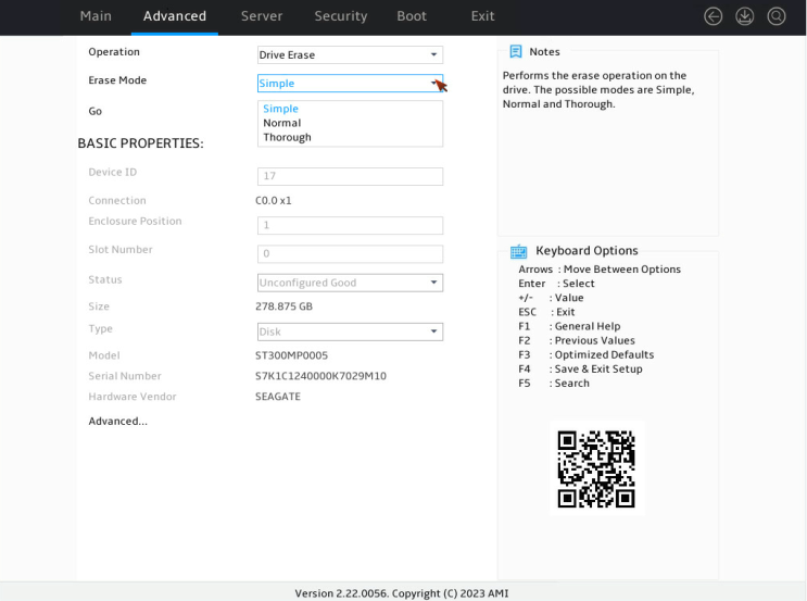
5. On the screen as shown in Figure 114, press Enter and set the Erase Mode (the default Simple mode is recommended).
Figure 114 Setting the Erase Mode
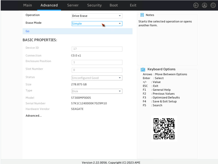
6. On the screen as shown in Figure 115, select Go and press Enter.
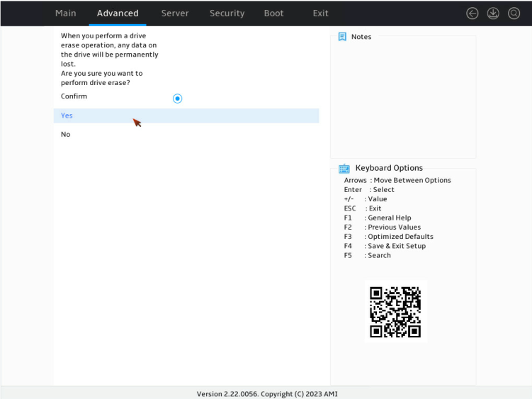
7. On the screen as shown in Figure 116, select Confirm. Then, select Yes and press Enter.
Figure 116 Confirming the operation
When the operation is complete, the screen as shown in Figure 117 opens.
Figure 117 Completing the operation
Erasing a logical drive
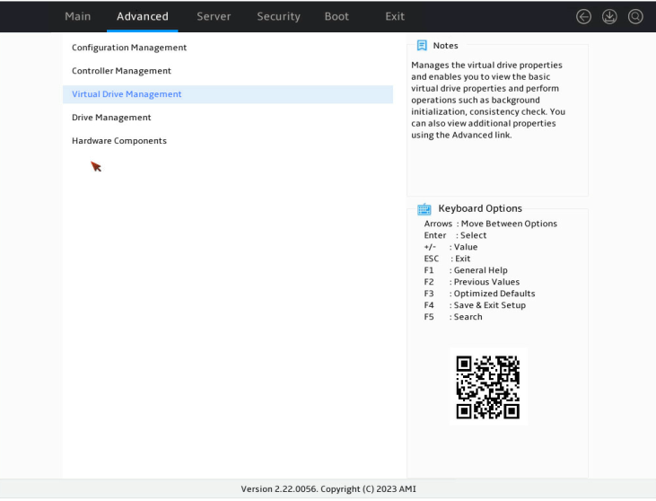
1. On the storage controller configuration screen as shown in Figure 118, select Virtual Drive Management and press Enter.
Figure 118 Storage controller configuration screen
2. On the screen as shown in Figure 119, select the target drive and press Enter.
Figure 119 Virtual Drive Management screen
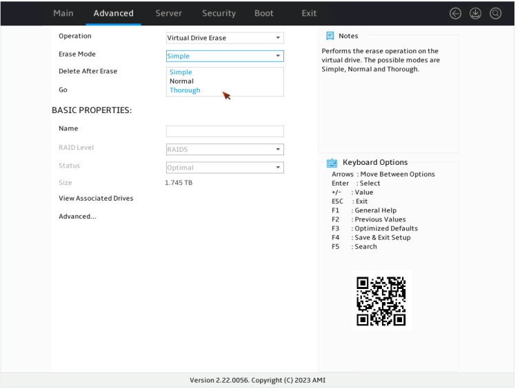
3. On the screen as shown in Figure 120, select Operation and press Enter. On the dialog box that appears, select Virtual Drive Erase and press Enter.
4. On the screen as shown in Figure 121, press Enter and set the Erase Mode (the default Simple mode is recommended).
Figure 121 Setting the Erase Mode
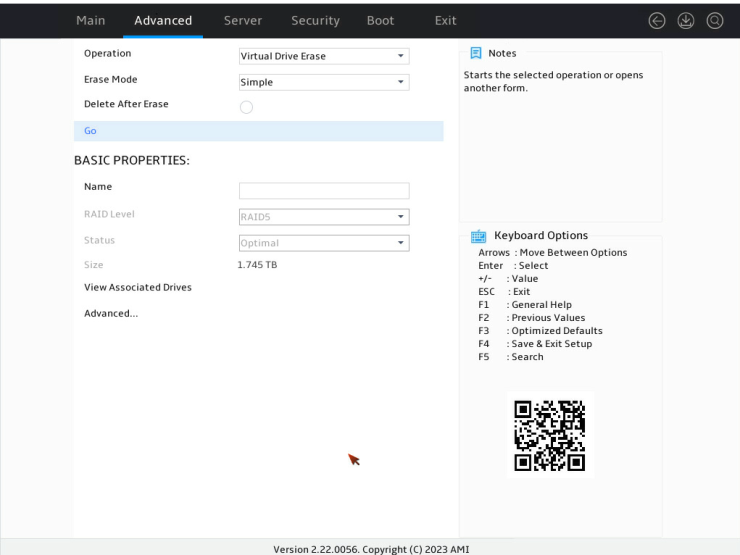
5. On the screen as shown in Figure 122, select Go and press Enter.
6. On the screen as shown in Figure 123, select Confirm. Then, select Yes and press Enter.
Figure 123 Confirming the operation

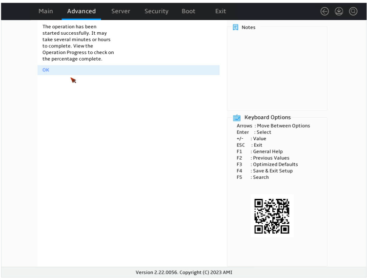
7. When the operation is complete, the screen as shown in Figure 124 opens.
Figure 124 Completing the operation
Expanding a RAID array
This task allows you to expand the RAID array capacity by setting the percentage of available logical drive capacity for availability purposes.
|
|
NOTE: The LSI 9540&9560 controller supports migration and scale-up in UEFI mode or the operating system only when the RAID level is 0, 1, 5, or 6. |
To expand a RAID array:
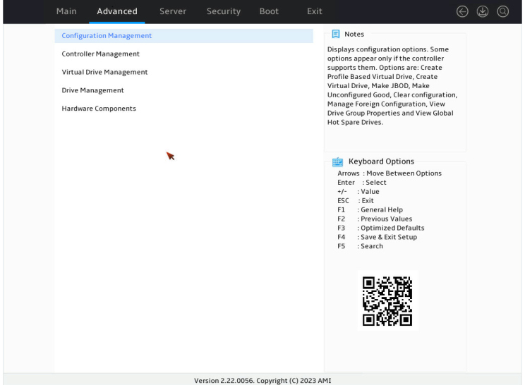
1. On the storage controller configuration screen as shown in Figure 125, select Virtual Drive Management and press Enter.
Figure 125 Storage controller configuration screen
2. On the screen as shown in Figure 126, select the target drive and press Enter.
Figure 126 Virtual Drive Management screen

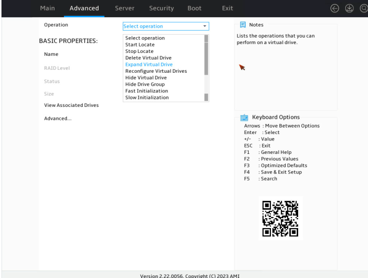
3. On the screen as shown in Figure 127, select Operation and press Enter. On the dialog box that appears, select Expand Virtual Drive and press Enter.
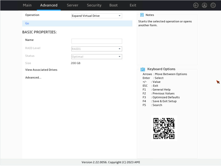
4. On the screen as shown in Figure 128, select Go and press Enter.
5. On the screen as shown in Figure 129, modify the value for Enter a Percentage of Available Capacity, select OK, and then press Enter.
Figure 129 Setting the percentage of available capacity

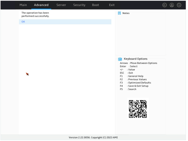
When the operation is complete, the screen as shown in Figure 130 opens.
Figure 130 Completing expanding a RAID array
Migrating the RAID level
This task allows you to change the RAID level without affecting data integrity.
|
|
NOTE: The LSI 9540&9560 controller supports migration and scale-up in UEFI mode or the operating system only when the RAID level is 0, 1, 5, or 6. |
To migrate the RAID level:
1. On the storage controller configuration screen as shown in Figure 131, select Virtual Drive Management and press Enter.
Figure 131 Storage controller configuration screen
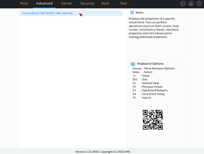
2. On the screen as shown in Figure 132, select the target drive and press Enter.
Figure 132 Virtual Drive Management screen

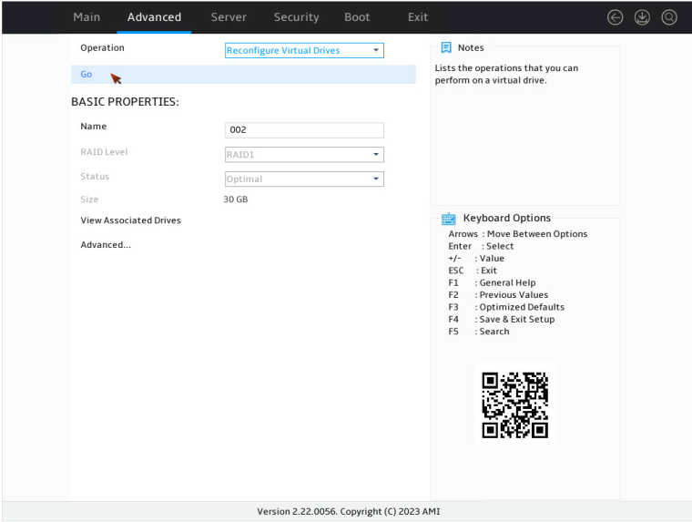
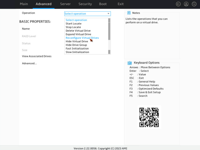
3. On the screen as shown in Figure 133, select Operation and press Enter. On the dialog box that appears, select Reconfigure Virtual Drive and press Enter.

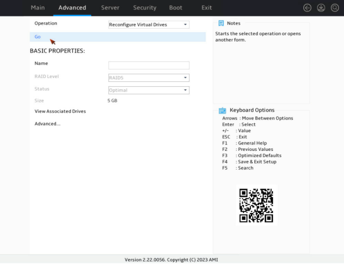
4. On the screen as shown in Figure 134, select Go and press Enter.
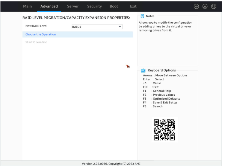
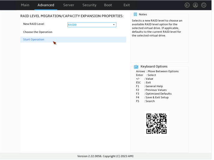
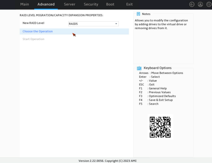
5. On the screen as shown in Figure 135, set the RAID level, select Choose the Operation, and then press Enter.
Figure 135 Choose the operation
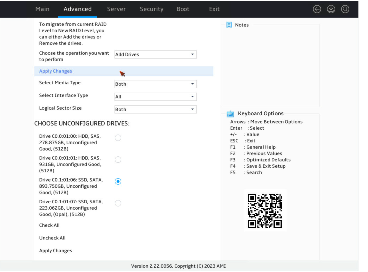
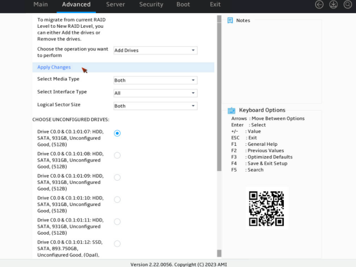
6. On the screen as shown in Figure 136, select the target drives. ([Enabled] following a drive means that the drive has been selected.) Then, select Apply Changes and press Enter.
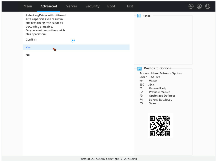
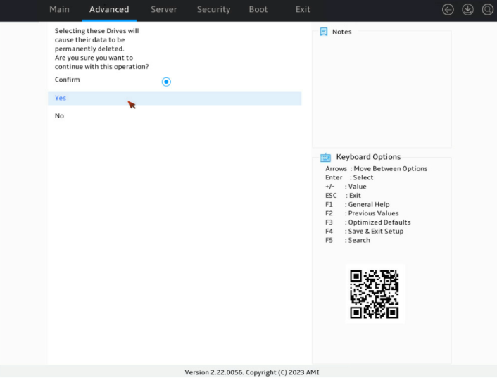
7. On the screen as shown in Figure 137, select Confirm. Then, select Yes and press Enter.
Figure 137 Confirming the operation
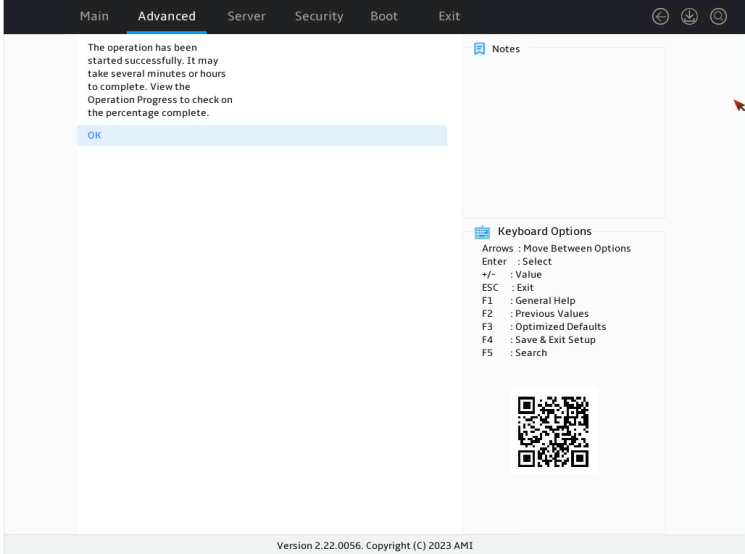
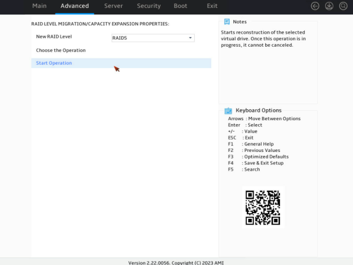
8. On the screen as shown in Figure 138, select Start Operation, and then press Enter.
Figure 138 Start the operation
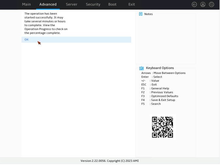
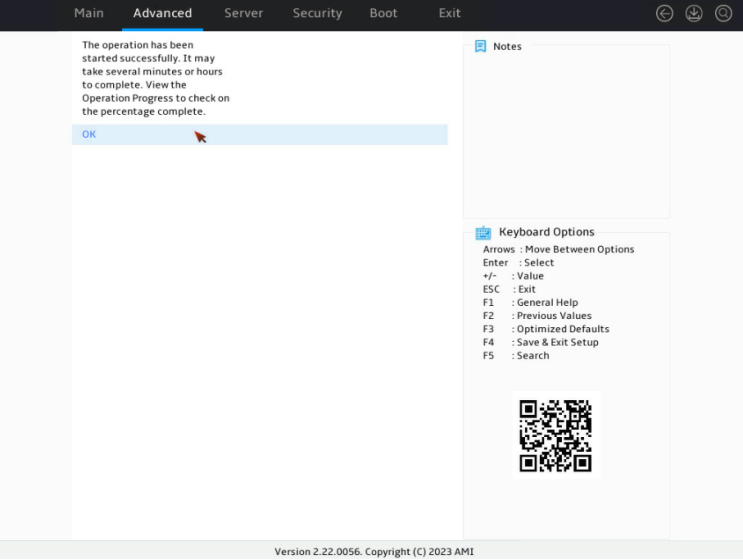
9. On the screen as shown in Figure 139, select OK, and then press Enter.
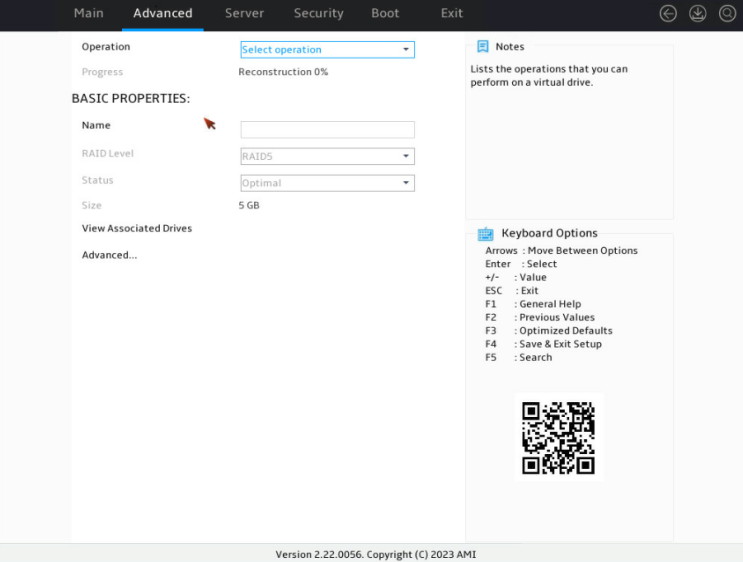
10. On the screen as shown in Figure 140, you can view the migration progress.
Figure 140 Viewing the migration progress

Clearing RAID array information on the drive
This task allows you to clear remaining RAID array information on the drive for reconfiguring RAID array on the drive. The task typically applies to drives in Unconfigured Bad state.
To clear RAID array information on the drive:
1. Switch the drive state from Unconfigured Bad to Unconfigured Good. For more information, see "Switching the drive state."
2. On the storage controller configuration screen as shown in Figure 141, select Configuration Management and press Enter.
Figure 141 Storage controller configuration screen
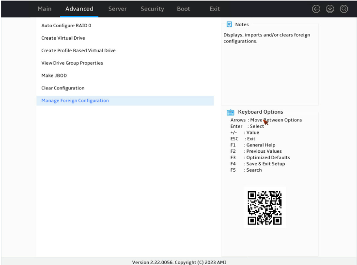
3. On the screen as shown in Figure 142, select Manage Foreign Configuration and press Enter.
Figure 142 Selecting Manage Foreign Configuration
4. On the screen as shown in Figure 143, select Clear Foreign Configuration and press Enter.
Figure 143 Selecting Clear Foreign Configuration

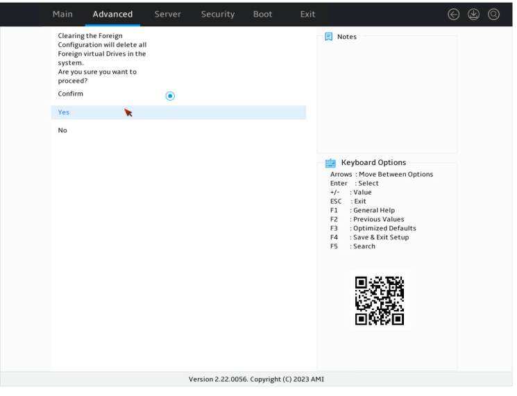
5. On the screen as shown in Figure 144, select Confirm. Then, select Yes and press Enter.
Figure 144 Confirming the operation
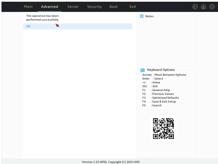
When the operation is complete, the screen as shown in Figure 145 opens.
Figure 145 Completing the operation
Hiding a virtual drive
This task allows you to hide a virtual drive to avoid unintentional deletion.
To hide a virtual drive:
1. On the storage controller configuration screen as shown in Figure 146, select Virtual Drive Management and press Enter.
Figure 146 Storage controller configuration screen
2. On the screen as shown in Figure 147, select the target drive and press Enter.
Figure 147 Virtual Drive Management screen
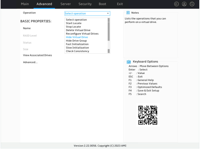
3. On the screen as shown in Figure 148, select Operation and press Enter. On the dialog box that appears, select Hide Virtual Drive and press Enter.
Hiding a RAID array
This task allows you to hide a RAID array to avoid unintentional deletion. If you hide a RAID array, all the virtual drives of the RAID array are hidden.
To hide a RAID array:
1. On the storage controller configuration screen as shown in Figure 149, select Virtual Drive Management and press Enter.
Figure 149 Storage controller configuration screen

2. On the screen as shown in Figure 150, select the target drive and press Enter.
Figure 150 Virtual Drive Management screen

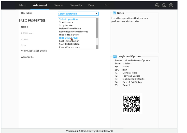
3. On the screen as shown in Figure 151, select Operation and press Enter. On the dialog box that appears, select Hide Drive Group and press Enter.
Upgrading the storage controller firmware online
To use a USB drive for the firmware upgrade, save the firmware file in the root directory or a level-1 folder of the USB drive.
To upgrade the storage controller firmware online:
1. On the Advanced screen as shown in Figure 152, select Update Firmware and press Enter.

2. On the screen as shown in Figure 153, select the directory of the target firmware and press Enter.
Figure 153 Selecting directory
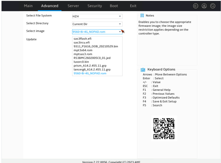
3. On the screen as shown in Figure 154, select the image file of the target firmware and press Enter.

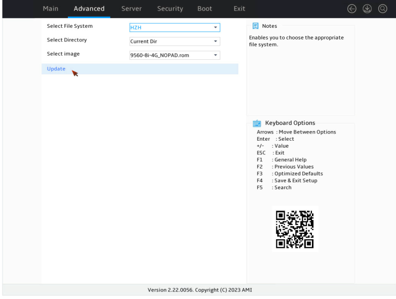
4. On the screen as shown in Figure 155, select Update and press Enter.
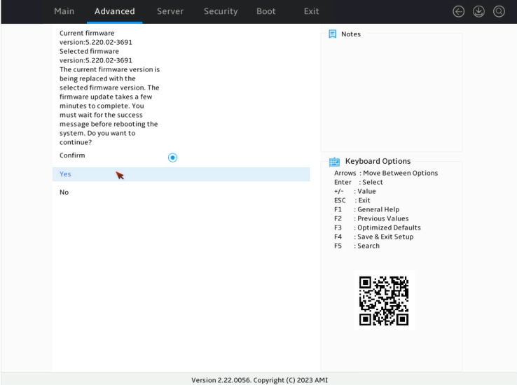
5. On the screen as shown in Figure 156, select Confirm. Then, select Yes and press Enter.
|
|
CAUTION: After confirming the upgrade, the screen is stuck for a short time during which the firmware is being upgraded. Do not perform any other operations during this time. |
Figure 156 Confirming the operation
6. On the screen as shown in Figure 157, select OK and press Enter.
Figure 157 Completing the operation
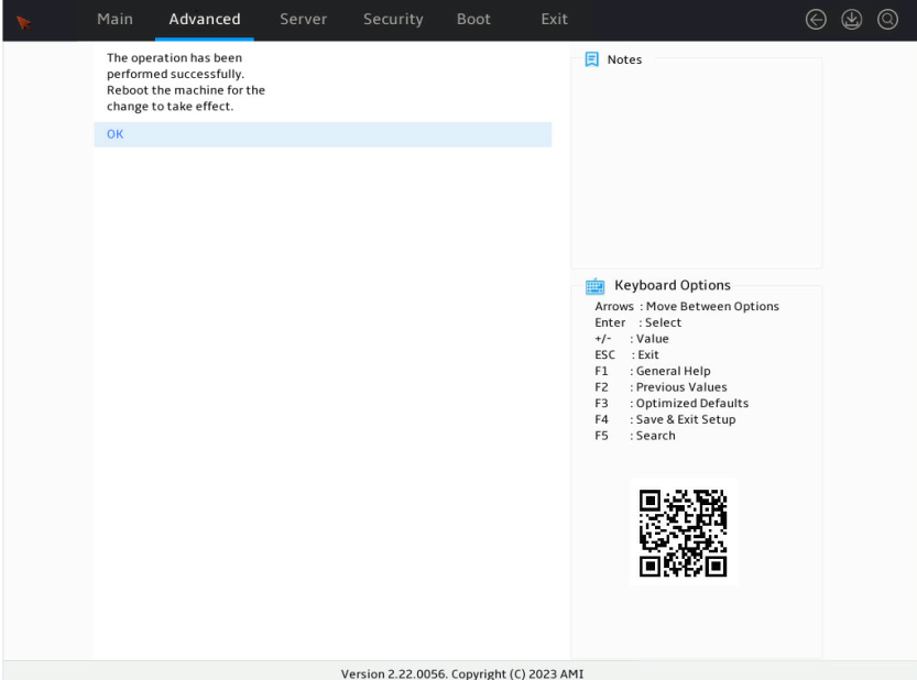
7. Restart the BIOS for the operation to take effect.
Switching the storage controller mode
1. On the Advanced menu, select Main Menu and press Enter.
Figure 158 Selecting Main Menu
2. Select Controller Management and press Enter.
Figure 159 Selecting Controller Management
3. Select Advanced Controller Management and press Enter.
Figure 160 Selecting Advanced Controller Management
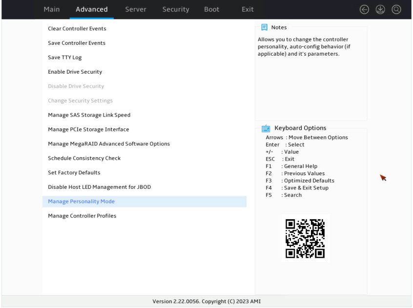
4. Select Manage Personality Mode and press Enter.
Figure 161 Selecting Manage Personality Mode
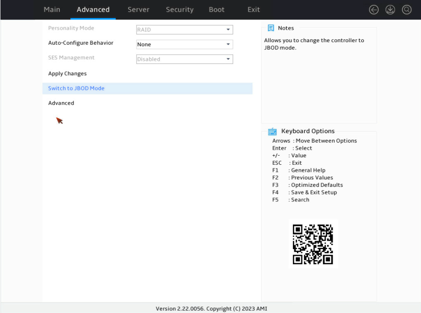
As shown in Figure 162, the storage controller is now is RAID mode. To switch the controller to JBOD mode, select Switch to JBOD Mode and press Enter.
Figure 162 Switching the controller to JBOD mode
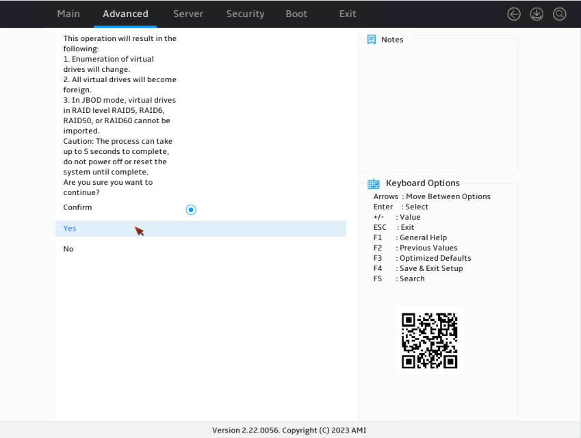
5. Select Confirm to enable the specified mode, select Yes and then press Enter.
|
|
CAUTION: When switching the storage controller to JBOD mode, you can also change logical drives managed by the controller to JBOD mode at the same time. Be careful that data might be cleared for logical drives that do not support JBOD mode once you switch the mode. As a best practice, before switching the mode of an LSI storage controller, change the drive state to Unconfigued Good. For example, logical drives in RAID 5, RAID 6, RAID 50, or RAID 60 managed by RAID-LSI-9560-LP-8i-4GB storage controller do not support JBOD mode and will be cleared if you switch their mode. For more information, see the screen prompt. |
Figure 163 Confirming the mode switching
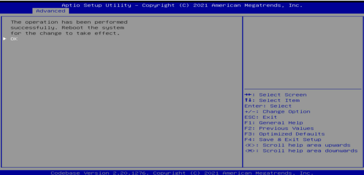
6. Select OK and press Enter to reboot the operating system for the change to take effect.
Figure 164 Completing the mode switching
Forcing a logical drive to come online
When the number of faulty drives exceeds the tolerance range of the logical drive fault-tolerant method, the management tool interface displays the state of logical drives as Offline. In this case, you can use this feature to force logical drives to come online.
|
|
CAUTION: Using this function may change data in the logical drive. Before forcing a logical drive to come online, perform an evaluation task to determine whether the operation can be performed. |
To force a logical drive to come online:
1. On the storage controller screen, select Virtual Drive Management and then press Enter.
Figure 165 Storage controller screen

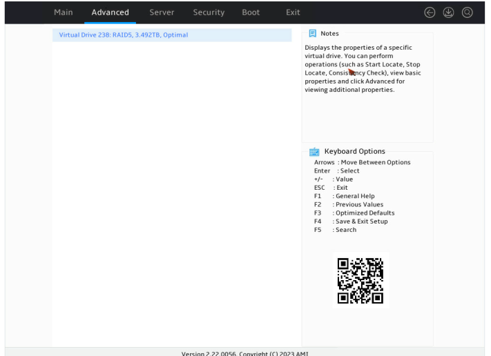
2. Select the target logical drive, and then press Enter.
Figure 166 Virtual Drive Management screen
3. Select View Associated Drives and then press Enter.
Figure 167 Selecting View Associated Drives
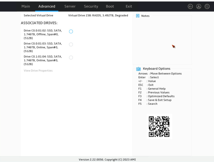
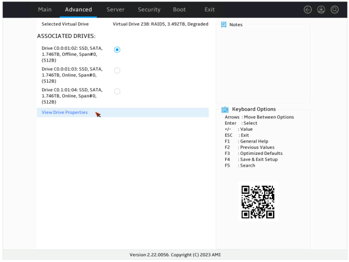
4. Select the target offline member drive, enable the drive, select View Drive Properties, and then press Enter.
Figure 168 Selecting View Drive Properties
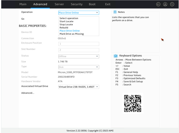
5. Select Operation, press Enter, select Place Drive Online, and then press Enter again.
Figure 169 Selecting Place Drive Online
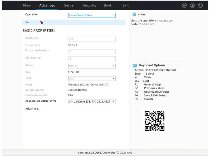
6. Select Go and then press Enter.
7. Select Confirm. Then, select Yes and press Enter.
Figure 171 Confirming the operation
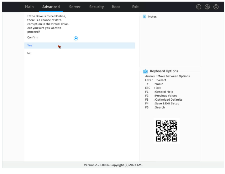
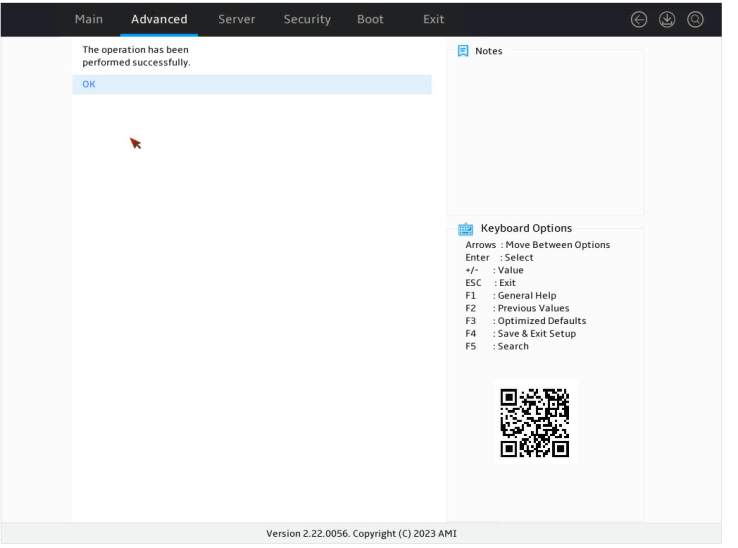
Figure 172 Operation succeeded
Adding new drives to a RAID array
Perform this task to add new drives to a RAID array for expansion.
Restrictions and guidelines
The LSI-9540 or 9560 series storage controller supports migration or expansion in UEFI mode or in the OS only in RAID 0, 1, 5, or 6.
A storage controller does not support simultaneously reconfiguring two RAID arrays, which involves reconfiguring virtual drives, including drive expansion or RAID level migration. You must reconfigure a RAID array one by one.
A newly added drive must be of the same type as the member drives in a RAID array, and its capacity cannot be smaller than the minimum capacity of the member drives in the RAID array.
For expansion with new drives, RAID 1 requires adding 2*N drives each time, and RAID 0, 1, 5, or 6 supports a maximum of 32 member drives.
Procedure
1. On the storage controller configuration screen as shown in Figure 173, select Virtual Drive Management and press Enter.
Figure 173 Storage controller configuration screen
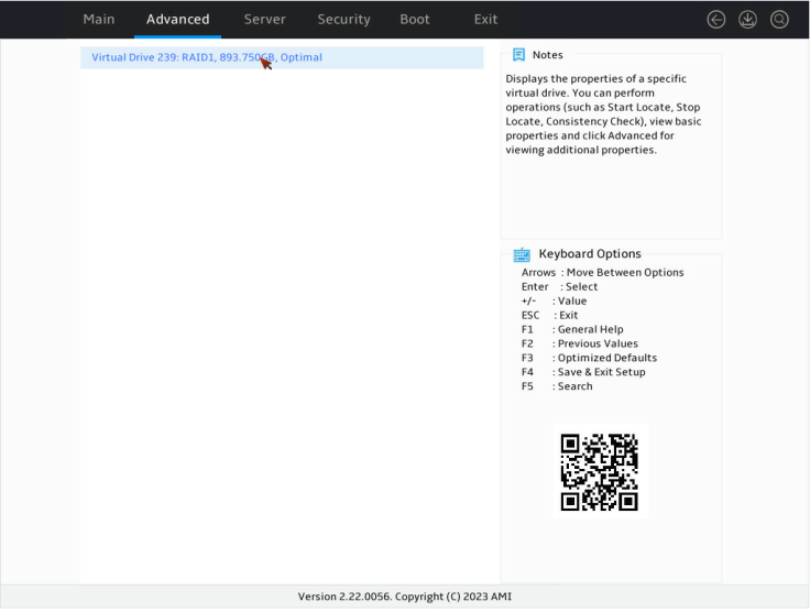
2. On the screen as shown in Figure 174, select the target logical drive and press Enter.
Figure 174 Virtual Drive Management screen
3. On the screen as shown in Figure 175, select Operation and press Enter. On the dialog box that opens, select Reconfigure Virtual Drives and press Enter.
4. On the screen as shown in Figure 176, select Go and press Enter.
5. On the screen as shown in Figure 177, set the RAID level, select Choose the Operation, and then press Enter.
Figure 177 Choosing the operation
6. On the screen as shown in Figure 178, select the drives to be added and click Apply Changes. Then, press Enter.
Figure 178 Choose the Operation screen
7. On the screen as shown in Figure 179, select Confirm. Then, select Yes and press Enter.
Figure 179 Confirming the operation
8. On the screen as shown in Figure 180, select OK and press Enter.
Figure 180 Completing drive selection

9. On the screen as shown in Figure 181, select Start Operation and press Enter.
Figure 181 Starting the operation
10. On the screen as shown in Figure 182, select OK and press Enter.
11. On the screen as shown in Figure 183, you can view the migration progress.
Figure 183 Viewing the migration progress
Viewing storage controller properties
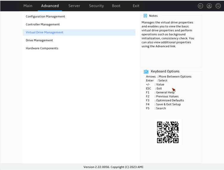
1. On the storage controller configuration screen as shown in Figure 184, select Virtual Drive Management and press Enter.
Figure 184 Storage controller configuration screen

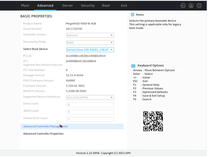
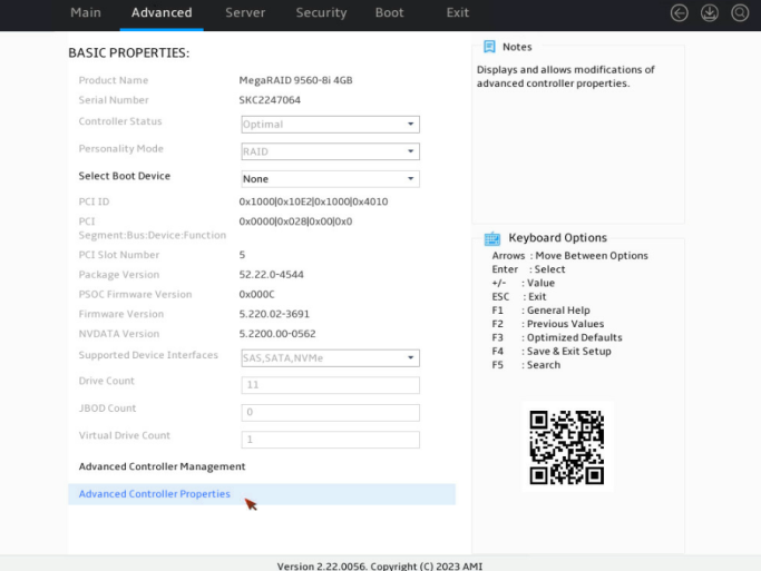
2. On the screen as shown in Figure 185, you can view the basic storage controller information and press Enter. For more information about storage controller properties, see Table 4.
Figure 185 Virtual Drive Management screen

Table 4 Parameter description
|
Parameter |
Description |
|
Product Name |
Storage controller name. |
|
Serial Number |
Serial number of the storage controller. |
|
Controller Status |
Operating status of the storage controller. |
|
Personality Mode |
Mode of the storage controller. |
|
Select Boot Device |
Boot option for the storage controller. This field specifies the boot option in legacy mode and the configuration takes effect only in legacy mode. |
|
PCI ID |
PCI ID of the storage controller. |
|
PCI Segment:Bus:Device:Fuction |
PCI address of the storage controller in the format of bus number:device number:function number. |
|
PCI Slot Number |
PCIe slot number of the storage controller. |
|
Package Version |
Package version of the storage controller. |
|
PSOC Firmware Version |
PSOC firmware version of the storage controller. |
|
Firmware Version |
Firmware version of the storage controller. |
|
NVDATA Version |
NVDATA version of the storage controller. |
|
Drive Count |
Number of the drives attached to the storage controller. |
|
Virtual Drive Count |
Number of virtual drives that are already attached to the storage controller. |
|
Advanced Controller Management |
Submenus for more operations on the storage controller. |
|
Advanced Controller Properties |
Submenu for viewing and editing the advanced properties of the storage controller. |
3. On the storage controller management screen as shown in Figure 186, select Advanced Controller Properties and press Enter.
Figure 186 Advanced Controller Properties screen
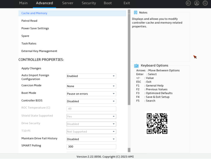
4. On the screen as shown in Figure 187, you can view and edit the advanced properties of the storage controller. For more information, see Table 5.
Figure 187 Advanced properties screen for the storage controller
|
Parameter |
Description |
|
Cache and Memory |
Cache and memory information of the storage controller. |
|
Patrol Read |
View and edit patrol properties, including start, terminate, recover, and suspend the patrol. |
|
Power Save Setting |
View and edit power settings for physical drives. |
|
Spare |
Edit properties related with emergency hot spare, hot spare, and drive replacement. |
|
Task Rates |
Set processing rates for tasks. |
|
Auto Import Foreign Configuration |
Select whether to enable automatic import of external configuration. |
|
Coercion Mode |
Specify the capacity compression mode of drives. |
|
Boot Mode |
Specify the action to be taken when the BIOS detects an exception. Options include: · Stop On Errors—The controller BIOS stops the startup when detecting an exception and can continue the startup only after user confirmation. · Pause on Errors—The controller BIOS suspends the startup when detecting an exception and will continue the startup after a certain period of time without user confirmation. This is the default option. · Ignore Errors—The controller BIOS continues the startup by ignoring an exception when detecting the exception. This option is typically used for system diagnosis. · Safe Mode on Errors—The controller BIOS uses the safe startup mode when detecting an exception. |
|
Controller BIOS |
Specify the BIOS enablement status, which is enabled by default. |
|
ROC Temperature |
Temperature of the storage controller. |
|
Shield State Supported |
Select whether to support I/O interruption for drive diagnosis. The default is Yes. |
|
Drive Security |
Enabling status of drive encryption. |
|
T10-PI |
Enabling status of information protection technology. |
|
Maintain Drive Fail History |
S elect whether to enable drive fault recording. The default is Enabled. If this field is set to Disabled, a drive will automatically rebuilds the data of the faulty drive when one of the following conditions is met: · A new drive is installed regardless of whether the new drive has RAID configuration. · A drive in the redundant RAID array is hot swapped online. If this field is set to Enabled, the following rules apply: · When a new drive without RAID configuration is installed, the new drive will automatically rebuild the data of the faulty drive. · When you install a new drive with RAID configuration or hot swap a drive in the redundant RAID array, the drive status will be marked as Unconfigured Bad (Foreign) and the rebuild operation will not be automatically performed. To rebuild RAID for this drive, set the drive status to Unconfigured Good. For more information, see "Importing foreign configuration" and "Clearing foreign configuration." If you hot swap a drive in JBOD online state, the drive status will be marked as Unconfigured Bad. You must switch the drive status manually as needed. |
|
SMART Polling |
Specify the SMART polling interval. |
|
Stop Consistency Check on Error |
Select whether to stop consistency check upon errors. |
|
JBOD Mode |
Specify the enabling status of JBOD mode. |
|
Write Verify |
Verify data write. |
|
Large IO Support |
Select whether to enable large I/O support. |
|
Unmap Capability |
Select whether to enable the unmapping capability. |
|
Firmware Device order |
Select whether to enable the firmware device order feature. Options include: · Disabled—During the server reboot phase, the devices under the storage controller are reported individually or as logical drives. This option is the default. · Enabled—After this feature is enabled, the reporting order of devices under the storage controller during the server reboot phase will change to boot drives, logical drives, and then individual drives. This feature is only applicable to Linux. |
|
Apply Changes |
View and edit the advanced storage controller properties. |
|
Display of some parameters depends on the storage controller firmware. |
|
Importing foreign configuration
Perform this task to import the configuration of an old storage controller to a new storage controller after the old storage controller is replaced.
Restrictiond and guidelines
On the server with RAID configuration, after a storage controller is replaced, the current RAID configuration will be identified as Foreign Configuration. In this case, if you clear foreign configuration, the RAID configuration will get lost.
To avoid failure in importing foreign configuration, replace a storage controller with a new one of the same model.
When the number of failed or missing drives exceeds the maximum allowable by a RAID array, the RAID array cannot be imported successfully.
Procedure
1. On the storage controller configuration screen as shown in Figure 188, select Configuration Management and press Enter.
Figure 188 Storage controller configuration screen

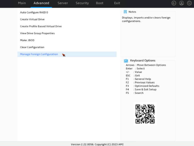
2. On the screen as shown in Figure 189, select Manage Foreign Configuration and press Enter.
Figure 189 Configuration Management screen

3. On the screen as shown in Figure 124, select Preview Foreign Configuration and press Enter to display the current detailed foreign configuration.
Figure 190 Manage Foreign Configuration screen

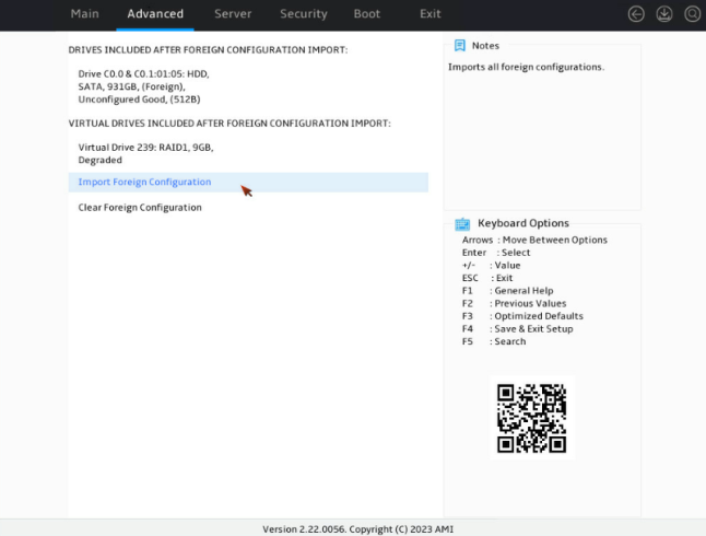
4. On the screen as shown in Figure 191, select Import Foreign Configuration and press Enter.
Figure 191 Preview Foreign Configuration screen
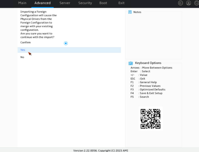
5. On the screen as shown in Figure 124, select Confirm. Then, select Yes and press Enter.
Figure 192 Confirming the operation
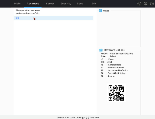
6. On the screen as shown in Figure 193, select OK and press Enter.
Figure 193 Completing importing the foreign configuration
Clearing foreign configuration
1. On the storage controller configuration screen as shown in Figure 124, select Configuration Management and press Enter.
Figure 194 Storage controller configuration screen

2. On the screen as shown in Figure 124, select Manage Foreign Configuration and press Enter.
Figure 195 Configuration Management screen
3. On the screen as shown in Figure 124, select Preview Foreign Configuration and press Enter to display the current detailed foreign configuration.
Figure 196 Manage Foreign Configuration screen
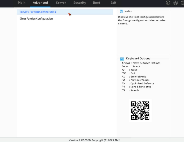
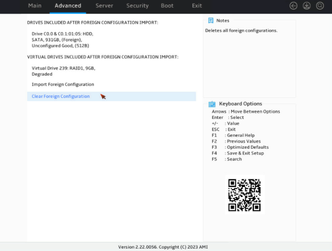
4. On the screen as shown in Figure 197, select Clear Foreign Configuration and press Enter.
Figure 197 Preview Foreign Configuration screen
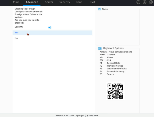
5. On the screen as shown in Figure 198, select Confirm. Then, select Yes and press Enter.
Figure 198 Confirming the operation
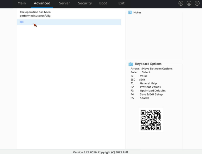
6. On the screen as shown in Figure 199, select OK and press Enter.
Figure 199 Completing the clear operation
Creating multiple virtual drives
1. On the storage controller configuration screen as shown in Figure 200, select Configuration Management and press Enter.
Figure 200 Storage controller configuration screen
2. On the screen as shown in Figure 201, select Create Virtual Drive and press Enter.
Figure 201 Selecting Create Virtual Drive
3. On the screen as shown in Figure 202, select Select RAID Level to set the RAID level, for example RAID 1, and then press Enter.
Figure 202 Setting the RAID level
4. On the screen as shown in Figure 203, select Select Drives From to set the drive capacity source, and then press Enter.
¡ Unconfigured Capacity—The capacity source is the unconfigured drives. This example selects Unconfigured Capacity as an example.
¡ Free Capacity—The capacity source is the remaining drive capacity of the drives that have been used for RAID setup.
Figure 203 Selecting Select Drives From
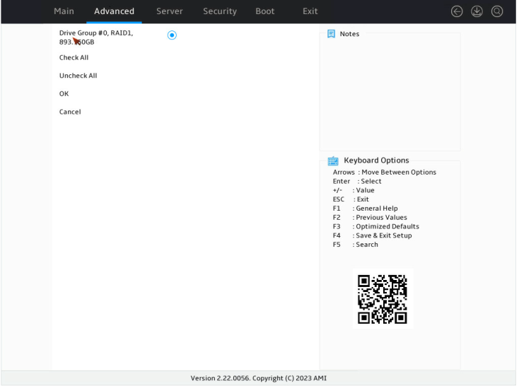
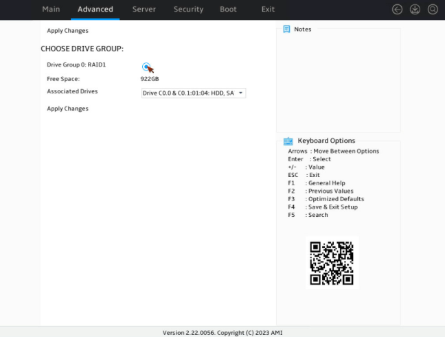
5. On the screen as shown in Figure 204, select Select Drives Group and select the drive group for RAID setup, and then press Enter.
Figure 204 Selecting Select Drives group
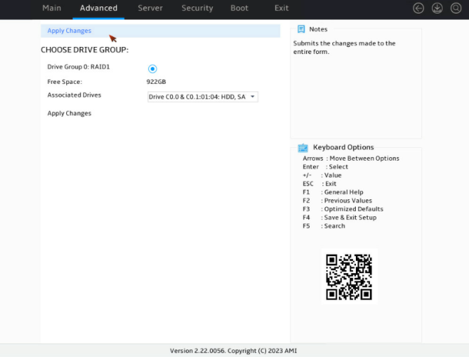
6. On the screen as shown in Figure 205, select Apply Changes and press Enter.
Figure 205 Selecting Apply Changes
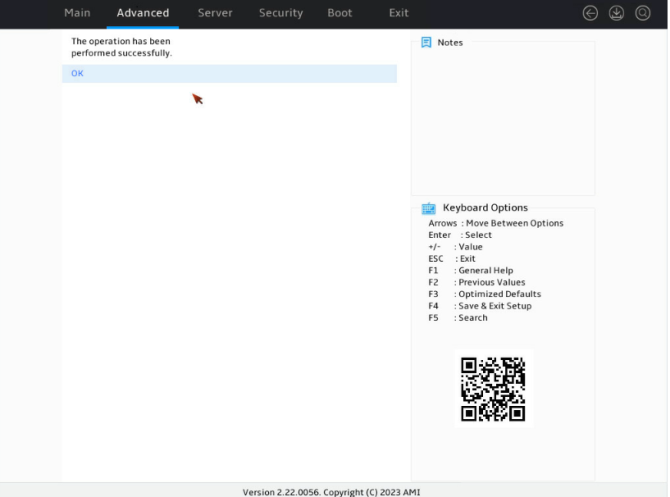
7. On the screen as shown in Figure 206, complete the drive group selection. Select OK and press Enter.
Figure 206 Completing drive group selection
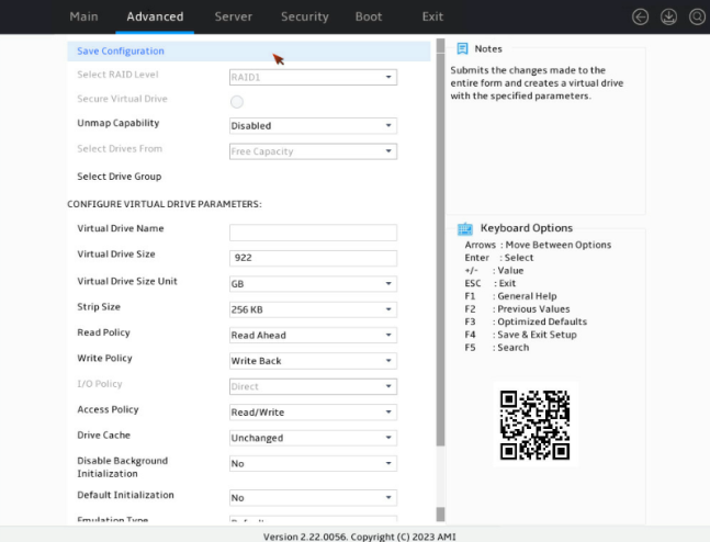
8. On the screen as shown in Figure 207, configure the related parameters, select Save Configuration, and press Enter.
Figure 207 Configuring the parameters
9. On the screen as shown in Figure 208, select Confirm. Then, select Yes and press Enter.
Figure 208 Confirming the operation
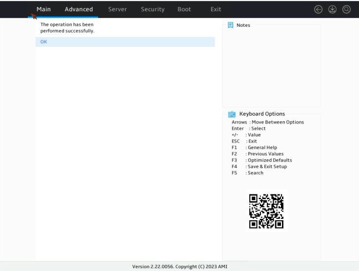
10. On the screen as shown in Figure 209, select OK and press Enter.
Figure 209 Completing the configuration

Configuring RAID arrays in legacy mode
The storage controllers in this section support legacy mode but do not support the management interface in legacy mode.
Downloading and installing StorCLI
This section introduces the download and installation steps of the OS command line tool. You can use the OS command line tool to manage storage controllers during normal server operation without restarting the server.
Downloading StorCLI
1. Access https://www.h3c.com/cn/BizPortal/DownLoadAccessory/DownLoadAccessoryFilt.aspx.
2. Download the installation package and release notes for the corresponding storage controller firmware as instructed.
3. Decompress the installation package to obtain the StorCLI tool package for different operating systems.
Installing StorCLI
See the release notes to install StorCLI for the corresponding operating system.
Commonly-used commands in StorCLI
This section describes the usage and examples of commonly used commands in StorCLI. You can use the OS command line tool to manage storage controllers during normal server operation without restarting the server.
|
|
NOTE: All the commands related with specifying paths in StorCLI do not support spaces and special characters. |
Viewing storage controller information
Perform this task to view basic information about an LSI storage controller.
Syntax
storcli64 /ccontroller_id show [ all ]
Parameters
controller_id: Specifies the ID of a storage controller. If only one storage controller exists, the ID is 0 by default. If multiple storage controllers exist, use the storcli64 /call show command to view the controller ID.
all: Specifies all storage controllers.
Examples
# View basic information about a storage controller.
[root@localhost home]# ./storcli64 /c0 show
Generating detailed summary of the adapter, it may take a while to complete.
CLI Version = 007.1017.0000.0000 May 10, 2019
Operating system = Linux 4.18.0-193.el8.x86_64
Controller = 0
Status = Success
Description = None
Product Name = AVAGO MegaRAID SAS 9361-8i
Serial Number = SK64909030
SAS Address = 500605b00c980df0
PCI Address = 00:3b:00:00
System Time = 03/08/2022 20:23:05
Mfg. Date = 12/22/16
Controller Time = 03/08/2022 12:23:05
FW Package Build = 24.21.0-0148
BIOS Version = 6.36.00.3_4.19.08.00_0x06180205
FW Version = 4.680.00-8555
Driver Name = megaraid_sas
Driver Version = 07.710.50.00-rc1
Current Personality = RAID-Mode
Vendor Id = 0x1000
Device Id = 0x5D
SubVendor Id = 0x1000
SubDevice Id = 0x9361
Host Interface = PCI-E
Device Interface = SAS-12G
Bus Number = 59
Device Number = 0
Function Number = 0
Physical Drives = 2
PD LIST :
=======
-------------------------------------------------------------------------------
EID:Slt DID State DG Size Intf Med SED PI SeSz Model Sp Type
-------------------------------------------------------------------------------
2:8 39 UGood - 5.457 TB SATA HDD N N 512B ST6000NM0115-1YZ110 U -
2:23 61 UGood - 1.818 TB SATA HDD N N 512B ST2000NM0125-1YZ104 U -
-------------------------------------------------------------------------------
EID=Enclosure Device ID|Slt=Slot No.|DID=Device ID|DG=DriveGroup
DHS=Dedicated Hot Spare|UGood=Unconfigured Good|GHS=Global Hotspare
UBad=Unconfigured Bad|Onln=Online|Offln=Offline|Intf=Interface
Med=Media Type|SED=Self Encryptive Drive|PI=Protection Info
SeSz=Sector Size|Sp=Spun|U=Up|D=Down|T=Transition|F=Foreign
UGUnsp=Unsupported|UGShld=UnConfigured shielded|HSPShld=Hotspare shielded
CFShld=Configured shielded|Cpybck=CopyBack|CBShld=Copyback Shielded
UBUnsp=UBad Unsupported
Switching the storage controller mode
Perform this task to switch the storage controller mode.
Syntax
storcli64 /ccontroller_id set personality =mode
Default
A storage controller operates in RAID mode.
Parameters
controller_id: Specifies the ID of a storage controller. If only one storage controller exists, the ID is 0 by default. If multiple storage controllers exist, use the storcli64 /call show command to view the controller ID.
mode: Specifies the controller mode. Options include:
· raid: Specifies the RAID mode.
· jbod: Specifies the JBOD mode.
Usage guidelines
· Before switching the controller mode to JBOD, make sure the storage controller is using the most recent version. Lower versions may not support the JBOD mode.
· Before using this command, make sure all drives managed by the storage controller are in Unconfigured Good state.
· For the configuration to take effect, you must restart the operating system after executing the command.
Examples
# Switch the storage controller mode to JBOD.
[root@localhost home]# ./storcli64 /c0 set personality=jbod
CLI Version = 007.1017.0000.0000 May 10, 2019
Operating system = Linux 4.18.0-193.el8.x86_64
Controller = 0
Status = Success
Description = None
Controller Properties :
=====================
------------------------------------------------------------------------
Ctrl_Prop Value
------------------------------------------------------------------------
Set Personality JBOD (Reboot the system for the change to take effect.)
------------------------------------------------------------------------
Upgrading the firmware
Perform this task to upgrade the firmware of a storage controller.
Syntax
storcli64 /ccontroller_id download file= fw_file
Parameters
controller_id: Specifies the ID of a storage controller. If only one storage controller exists, the ID is 0 by default. If multiple storage controllers exist, use the storcli64 /call show command to view the controller ID.
fw_file: Specifies the firmware file name.
Usage guidelines
If the firmware file does not exist in the current path, you must add the absolute path to the file name.
Examples
# Upgrade the storage controller firmware.
[root@localhost home]# ./storcli64 /c0 download file=MR_4MB.rom noverchk
Download Completed.
Flashing image to adapter...
CLI Version = 007.1017.0000.0000 May 10, 2019
Operating system = Linux 4.18.0-193.el8.x86_64
Controller = 0
Status = Success
Description = F/W Flash Completed. Please reboot the system for the changes to take effect
Creating and deleting RAID arrays
Perform this task to create and delete RAID arrays.
Syntax
To create a RAID array:
storcli64 /ccontroller_id add vd rraid_level [size=<vd1_size>,..] [name=<vdname1>,..] drives= vd_drives [pdperarray= pdperarraynum] [pdcache=pdcache_policy] [pi] [wt|wb|awb] [nora|ra] [strip=strip_size] [emulationtype=emulationtype] [spares =spares_drives]
To delete a RAID array:
storcli64 /ccontroller_id/vraid_id del
Parameters
controller_id: Specifies the ID of a storage controller. If only one storage controller exists, the ID is 0 by default. If multiple storage controllers exist, use the storcli64 /call show command to view the controller ID.
raid_level: Specifies the RAID level. Options include 0, 1, 5, 6, 00, 10, 50, and 60.
vd1_size: Specifies the capacity of the RAID array, in gb. If you specify all, it indicates that the array can use all the available capacity.
vdname1: Specify the name of the logical drive.
vd_drives: Specifies member drives. The name of each member drive must be in the enclosure_id:slot_id format, where enclosure_id represents the ID the enclosure in which the drive resides, and slot_id represents the drive slot ID.
pdperarraynum: Specifies the number of drives in the sub-group if the RAID level is 10, 50, or 60.
pdcache_policy: Specifies the cache state for member drives. Options include on, off, and default. Setting this field to default represents retaining the current cache state.
pi: Enables data protection.
wt|wb|awb: Specifies the write cache policy. Write through (wt) notifies the system of transmission completion when data are written into disks. Write back (wb) notifies the system of transmission completion when data are written into the controller cache. Always write back (awb) forces the system to use write back when no supercapacitor is present, which may cause data loss in the event of unexpected power-off.
nora|ra: Specifies the read cache policy. When reading data from RAID, the ra policy enables the system to read the surrounding data and store them in the cache at the same time. When the user accesses these data subsequently, they can be directly read from the cache, which reduces the disk seeking time and improves read performance.
strip_size: Specifies the strip size. For an MR controller, options include 8, 16, 32, 64, 128, 256, 512, and 1024. For an iMR controller, only 64 is supported. Among all the controllers supported by this document, only the HBA-LSI-9440-8i is an iMR controller.
emulationtype: Options include 0, 1, and 2. By default, the value is 0. 0: Displays the sector size as 512e if member drives include a 512e drive, and 512n if member drives do not include 512e drives. 1: Displays the sector size 512n if member drives do not include 512e drives. 2: Displays the sector size as 512e even if member drives do not include 512e drives.
spares_drives: Specifies hot spare drives. The name of each hot spare drive is in the format of enclosure_id:slot_id.
raid_id: Specifies the ID of the RAID array to be deleted. To obtain the ID, use the ./storcli64 /c0/vall show command. If you specify this field to all, the command deletes all the RAID arrays.
Usage guidelines
When you specify member drives, use a comma (,) to separate two slots and use a hyphen (-) to indicate a slot range.
Examples
# Create RAID 1.
[root@localhost home]# ./storcli64 /c0 add vd r1 size=all drives=2:8,23
CLI Version = 007.1017.0000.0000 May 10, 2019
Operating system = Linux 4.18.0-193.el8.x86_64
Controller = 0
Status = Success
Description = Add VD Succeeded
[root@localhost home]# ./storcli64 /c0/v0 del
CLI Version = 007.1017.0000.0000 May 10, 2019
Operating system = Linux 4.18.0-193.el8.x86_64
Controller = 0
Status = Success
Description = Delete VD succeeded
Locating a physical drive
Perform this task to turn on or turn off the UID LED of a physical drive.
Syntax
storcli64 /ccontroller_id/eenclosure_id/sslot_id action locate
Parameters
controller_id: Specifies the ID of a storage controller. If only one storage controller exists, the ID is 0 by default. If multiple storage controllers exist, use the storcli64 /call show command to view the controller ID.
enclosure_id: Specifies the enclosure ID. If you specify this field as all, the command turns on the UID LEDs for all drives in all enclosures.
slot_id: Specifies the ID of the physical drive slot. If you specify this field as all, the command turns on the UID LEDs for all drives in the enclosure.
action: Specifies the action to take. Options include:
· start: Turn on the UID LED.
· stop: Turn off the UID LED.
Examples
# Turn on the drive UID LED.
[root@localhost home]# ./storcli64 /c0/e2/s8 start locate
CLI Version = 007.1017.0000.0000 May 10, 2019
Operating system = Linux 4.18.0-193.el8.x86_64
Controller = 0
Status = Success
Description = Start Drive Locate Succeeded.
# Turn off the drive UID LED.
[root@localhost home]# ./storcli64 /c0/e2/s8 stop locate
CLI Version = 007.1017.0000.0000 May 10, 2019
Operating system = Linux 4.18.0-193.el8.x86_64
Controller = 0
Status = Success
Description = Stop Drive Locate Succeeded.
Viewing the JBOD state
Perform this task to view the enabling status of the JBOD function for a storage controller.
Syntax
storcli64 /ccontroller_id jbod
Parameters
controller_id: Specifies the ID of a storage controller. If only one storage controller exists, the ID is 0 by default. If multiple storage controllers exist, use the storcli64 /call show command to view the controller ID.
Examples
# View the JBOD state.
[root@localhost home]# ./storcli64 /c0 show jbod
CLI Version = 007.1316.0000.0000 Mar 12, 2020
Operating system = Linux 3.10.0-862.el7.x86_64
Controller = 0
Status = Success
Description = None
Controller Properties :
=====================
----------------
Ctrl_Prop Value
----------------
JBOD ON
----------------
Setting the JBOD state
Perform this task to enable or disable the JBOD function for a storage controller in RAID mode.
Syntax
storcli64 /ccontroller_id set jbod=mode
Default
The JBOD function is disabled in RAID mode.
Parameters
controller_id: Specifies the ID of a storage controller. If only one storage controller exists, the ID is 0 by default. If multiple storage controllers exist, use the storcli64 /call show command to view the controller ID.
mode: Specifies the action to take. Options include:
· on: Enable JBOD.
· off: Disable JBOD.
Usage guidelines
This feature is supported only by the 9361, 9460, and 9440 controllers and controllers of the same series.
Examples
# Enable JBOD.
[root@localhost home]# ./storcli64 /c0 set jbod=on
CLI Version = 007.1017.0000.0000 May 10, 2019
Operating system = Linux 4.18.0-193.el8.x86_64
Controller = 0
Status = Success
Description = None
Controller Properties :
=====================
----------------
Ctrl_Prop Value
----------------
JBOD ON
----------------
# Disable JBOD.
[root@localhost home]# ./storcli64 /c0 set jbod=off
CLI Version = 007.1017.0000.0000 May 10, 2019
Operating system = Linux 4.18.0-193.el8.x86_64
Controller = 0
Status = Success
Description = None
Controller Properties :
=====================
----------------
Ctrl_Prop Value
----------------
JBOD OFF
----------------
Switching the drive state
Perform this task to switch the drive state between JBOD and Unconfigured Good.
Syntax
storcli64 /ccontroller_id/eenclosure_id/sslot_id set good [force]
storcli64 /ccontroller_id/eenclosure_id/sslot_id set jbod
Parameters
controller_id: Specifies the ID of a storage controller. If only one storage controller exists, the ID is 0 by default. If multiple storage controllers exist, use the storcli64 /call show command to view the controller ID.
enclosure_id: Specifies the enclosure ID.
slot_id: Specifies the ID of the physical drive slot.
Usage guidelines
Before switching the drive state from Unconfigured Good to JBOD, make sure the JBOD function is enabled for the storage controller.
Examples
# Switch the drive state to Unconfigured Good.
[root@localhost home]# ./storcli64 /c0/e2/s8 set good force
CLI Version = 007.1017.0000.0000 May 10, 2019
Operating system = Linux 4.18.0-193.el8.x86_64
Controller = 0
Status = Success
Description = Set Drive Good Succeeded.
# Switch the drive state to JBOD.
[root@localhost home]# ./storcli64 /c0/e2/s8 set jbod
CLI Version = 007.1017.0000.0000 May 10, 2019
Operating system = Linux 4.18.0-193.el8.x86_64
Controller = 0
Status = Success
Description = Set Drive JBOD Succeeded.
Viewing drive information
Perform this task to view basic drive information.
Syntax
storcli64 /ccontroller_id/eenclosure_id/sslot_id show [all]
Parameters
controller_id: Specifies the ID of a storage controller. If only one storage controller exists, the ID is 0 by default. If multiple storage controllers exist, use the storcli64 /call show command to view the controller ID.
enclosure_id: Specifies the enclosure ID.
slot_id: Specifies the ID of the physical drive slot.
Examples
[root@localhost home]# ./storcli64 /c0/e2/s8 show
CLI Version = 007.1017.0000.0000 May 10, 2019
Operating system = Linux 4.18.0-193.el8.x86_64
Controller = 0
Status = Success
Description = Show Drive Information Succeeded.
Drive Information :
=================
-------------------------------------------------------------------------------
EID:Slt DID State DG Size Intf Med SED PI SeSz Model Sp Type
-------------------------------------------------------------------------------
2:8 39 JBOD - 5.458 TB SATA HDD N N 512B ST6000NM0115-1YZ110 U -
-------------------------------------------------------------------------------
EID=Enclosure Device ID|Slt=Slot No.|DID=Device ID|DG=DriveGroup
DHS=Dedicated Hot Spare|UGood=Unconfigured Good|GHS=Global Hotspare
UBad=Unconfigured Bad|Onln=Online|Offln=Offline|Intf=Interface
Med=Media Type|SED=Self Encryptive Drive|PI=Protection Info
SeSz=Sector Size|Sp=Spun|U=Up|D=Down|T=Transition|F=Foreign
UGUnsp=Unsupported|UGShld=UnConfigured shielded|HSPShld=Hotspare shielded
CFShld=Configured shielded|Cpybck=CopyBack|CBShld=Copyback Shielded
UBUnsp=UBad Unsupported
Importing and exporting RAID configuration
Perform this task to save, restore, or import RAID configuration.
Syntax
storcli64 /ccontroller_id get config file=filename
storcli64 /ccontroller_id set config file=filename
Parameters
controller_id: Specifies the ID of a storage controller. If only one storage controller exists, the ID is 0 by default. If multiple storage controllers exist, use the storcli64 /call show command to view the controller ID.
filename: Specifies the configuration file name.
Usage guidelines
Before performing this task, make sure the server environments are identical for the source and target servers.
Examples
# Export RAID configuration.
[root@localhost home]# ./storcli64 /c0 get config file=conf.txt
CLI Version = 007.1017.0000.0000 May 10, 2019
Operating system = Linux 4.18.0-193.el8.x86_64
Controller = 0
Status = Success
Description = Config data is saved to the file
# Import RAID configuration.
[root@localhost home]# ./storcli64 /c0 set config file=conf.txt
CLI Version = 007.1017.0000.0000 May 10, 2019
Operating system = Linux 4.18.0-193.el8.x86_64
Controller = 0
Status = Success
Description = Config data is restored to the adapter
Scaling up RAID
Perform this task to scale up a RAID array.
Syntax
storcli64 /ccontroller_id/vraid_id expand size=target_size
Parameters
controller_id: Specifies the ID of a storage controller. If only one storage controller exists, the ID is 0 by default. If multiple storage controllers exist, use the storcli64 /call show command to view the controller ID.
raid_id: Specifies the ID of the RAID array to be scaled up.
target_size: Specifies the target capacity size.
Usage guidelines
The LSI 9540&9560 controllers support migration and scaling up in UEFI mode or the OS only when the RAID level is 0, 1, 5, or 6.
Examples
# Scale up the RAID capacity to 20Gb.
[root@localhost home]# ./storcli64 /c0/v0 expand size=20gb
CLI Version = 007.1017.0000.0000 May 10, 2019
Operating system = Linux 4.18.0-193.el8.x86_64
Controller = 0
Status = Success
Description = expansion operation succeeded
EXPANSION RESULT :
================
----------------------------------------------------------------------------
VD Size FreSpc ReqSize AbsUsrSz %FreSpc NewSize Status NoArrExp
----------------------------------------------------------------------------
0 10.000 GB 1.808 TB 20.000 GB 37.049 GB 2 47.049 GB - 1.808 TB
----------------------------------------------------------------------------
Size - Current VD size|FreSpc - Freespace available before expansion
%FreSpc - Requested expansion size in % of available free space
AbsUsrSz - User size rounded to nearest %
Migrating the RAID level
Perform this task to change the RAID level without affecting data integrity.
Syntax
storcli64 /ccontroller_id/vraid_id start migrate type=raidx option=operation drives= vd_drives force
Parameters
controller_id: Specifies the ID of a storage controller. If only one storage controller exists, the ID is 0 by default. If multiple storage controllers exist, use the storcli64 /call show command to view the controller ID.
raid_id: Specifies the ID of the RAID array to be scaled up.
raidx: Specifies the target RAID level.
vd_drives: Specifies member drives. The name of each member drive must be in the enclosure_id:slot_id format, where enclosure_id represents the ID the enclosure in which the drive resides, and slot_id represents the drive slot ID.
operation: Specifies whether to add or remove member drives. Options include add and remove.
Usage guidelines
The LSI 9540&9560 controllers support migration and scaling up in UEFI mode or the OS only when the RAID level is 0, 1, 5, or 6.
Examples
[root@localhost home]# ./storcli64 /c0/v0 start migrate type=raid5 option=add drives=2:11
CLI Version = 007.1017.0000.0000 May 10, 2019
Operating system = Linux 4.18.0-193.el8.x86_64
Controller = 0
Status = Success
Description = Start Reconstruction Operation Success
[root@localhost home]# ./storcli64 /c0/v0 start migrate type=raid0 option=remove drives=2:9
CLI Version = 007.1017.0000.0000 May 10, 2019
Operating system = Linux 4.18.0-193.el8.x86_64
Controller = 0
Status = Success
Description = Start Reconstruction Operation Success
Managing external configuration
Perform this task to import or delete external configuration.
Syntax
storcli64 /ccontroller_id/fall operation
Parameters
controller_id: Specifies the ID of a storage controller. If only one storage controller exists, the ID is 0 by default. If multiple storage controllers exist, use the storcli64 /call show command to view the controller ID.
operation: Specifies the action to take. Options include:
· import: Import external configuration.
· del: Delete external configuration.
Usage guidelines
If multiple storage controllers exist, use the storcli64 /call show command to obtain a controller ID.
Examples
# Import external configuration.
[root@localhost home]# ./storcli64 /c0/fall import
CLI Version = 007.1017.0000.0000 May 10, 2019
Operating system = Linux 4.18.0-193.el8.x86_64
Controller = 0
Status = Success
Description = Successfully imported foreign configuration
# Delete external configuration.
[root@localhost home]# ./storcli64 /c0/fall del
CLI Version = 007.1017.0000.0000 May 10, 2019
Operating system = Linux 4.18.0-193.el8.x86_64
Controller = 0
Status = Success
Description = Successfully deleted foreign configuration
Configuring hot spare drives
Perform this task to add hot spare drives for a redundant RAID array.
Syntax
storcli64 /ccontroller_id/eenclosure_id/sslot_id add hotsparedrive
storcli64 /ccontroller_id/eenclosure_id/sslot_id add hotsparedrive dgs=drive_group
storcli64 /ccontroller_id/eenclosure_id/sslot_id delete hotsparedrive
Default
If you do not specify the dgs keyword for an add operation, the command adds a global hot spare.
Parameters
controller_id: Specifies the ID of a storage controller. If only one storage controller exists, the ID is 0 by default. If multiple storage controllers exist, use the storcli64 /call show command to view the controller ID.
enclosure_id: Specifies the enclosure ID.
slot_id: Specifies the ID of the physical drive slot.
drive_group: Specify the drive group ID.
Usage guidelines
· If multiple storage controllers exist, use the storcli64 /call show command to obtain a controller ID.
· Hot spare disks must use consistent interface protocols as the member drives of the RAID array, and must have higher or the same capacity as the member drives.
Examples
# Add a global hot spare.
[root@localhost home]# ./storcli64 /c0/e2/s11 add hotsparedrive
CLI Version = 007.1017.0000.0000 May 10, 2019
Operating system = Linux 4.18.0-193.el8.x86_64
Controller = 0
Status = Success
Description = Add Hot Spare Succeeded.
# Add a dedicated hot spare.
[root@localhost home]# ./storcli64 /c0/e2/s8 add hotsparedrive dgs=0
CLI Version = 007.1017.0000.0000 May 10, 2019
Operating system = Linux 4.18.0-193.el8.x86_64
Controller = 0
Status = Success
Description = Add Hot Spare Succeeded.
# Delete a hot spare.
[root@localhost home]# ./storcli64 /c0/e2/s8 delete hotsparedrive
CLI Version = 007.1017.0000.0000 May 10, 2019
Operating system = Linux 4.18.0-193.el8.x86_64
Controller = 0
Status = Success
Description = Delete Hot Spare Succeeded.
Configuring emergency hot spare
Perform this task to enable emergency hot spare and configure whether to activate emergency hot spare upon a SMART error.
Syntax
storcli64 /ccontroller_id set eghs eug=state
storcli64 /ccontroller_id set eghs smarter=state
Parameters
controller_id: Specifies the ID of a storage controller. If only one storage controller exists, the ID is 0 by default. If multiple storage controllers exist, use the storcli64 /call show command to view the controller ID.
state: Specifies the enabling status of emergency hot spare. Options include on (enabled) and off (disabled).
Restrictions and guidelines
If multiple storage controllers exist, use the storcli64 /call show command to view the controller ID.
Examples
# Enable emergency hot spare and allows drives to use emergency hot spare upon a SMART error.
[root@localhost storcli]# ./storcli64 /c0 set eghs eug=on
CLI Version = 007.2507.0000.0000 Feb 07, 2023
Operating system = Linux 4.18.0-193.el8.x86_64
Controller = 0
Status = Success
Description = None
Controller Properties :
=====================
------------------
Ctrl_Prop Value
------------------
EmergencyUG ON
------------------
[root@localhost storcli]# ./storcli64 /c0 set eghs smarter=on
CLI Version = 007.2507.0000.0000 Feb 07, 2023
Operating system = Linux 4.18.0-193.el8.x86_64
Controller = 0
Status = Success
Description = None
Controller Properties :
=====================
-----------------------
Ctrl_Prop Value
-----------------------
EmergencySmarter ON
-----------------------
Collecting logs
Perform this task to export storage controller logs.
Syntax
storcli /ccontroller_id show alilog logfile=logfilename
Parameters
controller_id: Specifies the ID of a storage controller. If only one storage controller exists, the ID is 0 by default. If multiple storage controllers exist, use the storcli64 /call show command to view the controller ID.
logfilename: Specifies the log file name.
Examples
[root@localhost home]# ./storcli64 /c0 show alilog logfile=alilog.txt
Managing logs
Perform this task to filter or clear storage controller logs.
Syntax
storcli64 /ccontroller_id show termlog
storcli64 /ccontroller_id show events
storcli64 /ccontroller_id delete termlog
storcli64 /ccontroller_id delete events
Parameters
controller_id: Specifies the ID of a storage controller. If only one storage controller exists, the ID is 0 by default. If multiple storage controllers exist, use the storcli64 /call show command to view the controller ID.
Examples
[root@localhost home]# ./storcli64 /c0 show termlog
Firmware Term Log Information on controller 0:
03/13/22 9:12:37: C0:TTY History buffer cleared
CLI Version = 007.1017.0000.0000 May 10, 2019
Operating system = Linux 4.18.0-193.el8.x86_64
Controller = 0
Status = Success
Description = None
[root@localhost home]# ./storcli64 /c0 show events
seqNum: 0x00079e17
Time: Sun Mar 13 09:13:18 2022
Code: 0x0000001e
Class: 0
Locale: 0x20
Event Description: Event log cleared
Event Data:
===========
None
CLI Version = 007.1017.0000.0000 May 10, 2019
Operating system = Linux 4.18.0-193.el8.x86_64
Controller = 0
Status = Success
Description = None
Events = GETEVENTS
Controller Properties :
=====================
------------------------------------
Ctrl Status Method Value
------------------------------------
0 Success handleSuboption Events
------------------------------------
[root@localhost home]# ./storcli64 /c0 delete termlog
CLI Version = 007.1017.0000.0000 May 10, 2019
Operating system = Linux 4.18.0-193.el8.x86_64
Controller = 0
Status = Success
Description = None
Controller Properties :
=====================
----------------------------
Ctrl Method Result
----------------------------
0 Delete Termlog deleted
----------------------------
[root@localhost home]# ./storcli64 /c0 delete events
CLI Version = 007.1017.0000.0000 May 10, 2019
Operating system = Linux 4.18.0-193.el8.x86_64
Controller = 0
Status = Success
Description = None
Controller Properties :
=====================
---------------------------------
Ctrl Status Method Value
---------------------------------
0 Success DeleteEvents Events
---------------------------------
Configuring RAID cache settings
Perform this task to configure RAID cache settings.
Syntax
storcli64 /ccontroller_id/vraid_id set wrcache={wt|wb|awb}
storcli64 /ccontroller_id/vraid_id set rdcache={ra|nora}
Parameters
controller_id: Specifies the ID of a storage controller. If only one storage controller exists, the ID is 0 by default. If multiple storage controllers exist, use the storcli64 /call show command to view the controller ID.
raid_id: Specifies the target RAID ID.
{wt|wb|awb}: Specifies the write cache policy. Write through (wt) notifies the system of transmission completion when data are written into disks. Write back (wb) notifies the system of transmission completion when data are written into the controller cache. Always write back (awb) forces the system to use write back when no supercapacitor is present, which may cause data loss in the event of unexpected power-off.
{ra|nora}: Specifies the read cache policy. When reading data from RAID, the ra policy enables the system to read the surrounding data and store them in the cache at the same time. When the user accesses these data subsequently, they can be directly read from the cache, which reduces the disk seeking time and improves read performance.
Usage guidelines
If multiple storage controllers exist, use the storcli64 /call show command to obtain a controller ID.
Examples
[root@localhost home]# ./storcli64 /c0/v0 set wrcache=awb
CLI Version = 007.1017.0000.0000 May 10, 2019
Operating system = Linux 4.18.0-193.el8.x86_64
Controller = 0
Status = Success
Description = None
Detailed Status :
===============
---------------------------------------
VD Property Value Status ErrCd ErrMsg
---------------------------------------
0 wrCache AWB Success 0 -
---------------------------------------
[root@localhost home]# ./storcli64 /c0/v0 set rdcache=nora
CLI Version = 007.1017.0000.0000 May 10, 2019
Operating system = Linux 4.18.0-193.el8.x86_64
Controller = 0
Status = Success
Description = None
Detailed Status :
===============
---------------------------------------
VD Property Value Status ErrCd ErrMsg
---------------------------------------
0 rdCache NoRA Success 0 -
---------------------------------------
Setting the RAID access policy
Perform this task to configure the read and write permissions for RAID.
Syntax
storcli64 /ccontroller_id/vraid_id set accesspolicy={rw|ro|blocked}
Parameters
controller_id: Specifies the ID of a storage controller. If only one storage controller exists, the ID is 0 by default. If multiple storage controllers exist, use the storcli64 /call show command to view the controller ID.
raid_id: Specifies the target RAID ID.
{rw|ro|blocked}: Specifies the access policy. rw represents read and write, ro represents read-only, and blocked represents no access.
Usage guidelines
If multiple storage controllers exist, use the storcli64 /call show command to obtain a controller ID.
Examples
# Set the RAID access policy to read-only.
[root@localhost home]# ./storcli64 /c0/v0 set accesspolicy=rw
CLI Version = 007.1017.0000.0000 May 10, 2019
Operating system = Linux 4.18.0-193.el8.x86_64
Controller = 0
Status = Success
Description = None
Detailed Status :
===============
----------------------------------------
VD Property Value Status ErrCd ErrMsg
----------------------------------------
0 AccPolicy RW Success 0 -
----------------------------------------
Setting the read/write cache state for member drives
Perform this task to set the read and write cache state for member drives.
Syntax
storcli64 /ccontroller_id/vraid_id set pdcache= pdcache_policy
Parameters
controller_id: Specifies the ID of a storage controller. If only one storage controller exists, the ID is 0 by default. If multiple storage controllers exist, use the storcli64 /call show command to view the controller ID.
raid_id: Specifies the target RAID ID.
pdcache_policy: Specifies the cache policy. Options include on, off, and default. Setting this field to default represents retaining the current cache state.
Usage guidelines
If multiple storage controllers exist, use the storcli64 /call show command to obtain a controller ID.
Examples
# Disable the read/write cache.
[root@localhost home]# ./storcli64 /c0/v0 set pdcache=off
CLI Version = 007.1017.0000.0000 May 10, 2019
Operating system = Linux 4.18.0-193.el8.x86_64
Controller = 0
Status = Success
Description = None
Detailed Status :
===============
---------------------------------------
VD Property Value Status ErrCd ErrMsg
---------------------------------------
0 PdCac Off Success 0 -
Viewing the cache state of member drives
Perform this task to view the cache state of member drives.
Syntax
storcli64 /ccontroller_id /eenclosure_id/sslot_id show all
Parameters
controller_id: Specifies the ID of a storage controller. If only one storage controller exists, the ID is 0 by default. If multiple storage controllers exist, use the storcli64 /call show command to view the controller ID.
enclosure_id: Specifies the enclosure ID.
slot_id: Specifies the ID of the physical drive slot.
Usage guidelines
· If multiple storage controllers exist, use the storcli64 /call show command to obtain a controller ID.
· If you use this command to view the cache state of member drives for the LSI-9560 storage controller, the command output displays Write Cache = N/A.
Examples
# View the cache state of member drives.
[root@localhost ~]# storcli64 /c1 /e252/s10 show all
CLI Version = 007.1705.0000.0000 Mar 31, 2021
Operating system = Linux 4.18.0-193.el8.x86_64
Controller = 1
Status = Success
Description = Show Drive Information Succeeded.
Drive /c1/e252/s10 :
==================
---------------------------------------------------------------------------------
EID:Slt DID State DG Size Intf Med SED PI SeSz Model Sp Type
---------------------------------------------------------------------------------
252:10 20 Onln 0 893.750 GB SATA SSD N N 512B INTEL SSDSC2KB960G8 U -
---------------------------------------------------------------------------------
EID=Enclosure Device ID|Slt=Slot No|DID=Device ID|DG=DriveGroup
DHS=Dedicated Hot Spare|UGood=Unconfigured Good|GHS=Global Hotspare
UBad=Unconfigured Bad|Sntze=Sanitize|Onln=Online|Offln=Offline|Intf=Interface
Med=Media Type|SED=Self Encryptive Drive|PI=Protection Info
SeSz=Sector Size|Sp=Spun|U=Up|D=Down|T=Transition|F=Foreign
UGUnsp=UGood Unsupported|UGShld=UGood shielded|HSPShld=Hotspare shielded
CFShld=Configured shielded|Cpybck=CopyBack|CBShld=Copyback Shielded
UBUnsp=UBad Unsupported|Rbld=Rebuild
Drive /c1/e252/s10 - Detailed Information :
=========================================
Drive /c1/e252/s10 State :
========================
Shield Counter = 0
Media Error Count = 0
Other Error Count = 0
Drive Temperature = 36C (96.80 F)
Predictive Failure Count = 0
S.M.A.R.T alert flagged by drive = No
Drive /c1/e252/s10 Device attributes :
====================================
SN = PHYF832001H8960CGN
Manufacturer Id = ATA
Model Number = INTEL SSDSC2KB960G8
NAND Vendor = NA
WWN = 55CD2E414FA85A2E
Firmware Revision = XCV10120
Raw size = 894.252 GB [0x6fc81ab0 Sectors]
Coerced size = 893.750 GB [0x6fb80000 Sectors]
Non Coerced size = 893.752 GB [0x6fb81ab0 Sectors]
Device Speed = 6.0Gb/s
Link Speed = 6.0Gb/s
NCQ setting = Enabled
Write Cache = Enabled
Logical Sector Size = 512B
Physical Sector Size = 4 KB
Connector Name = C1.0 x1
Drive /c1/e252/s10 Policies/Settings :
====================================
Drive position = DriveGroup:0, Span:0, Row:0
Enclosure position = 1
Connected Port Number = 11(path0)
Sequence Number = 10
Commissioned Spare = No
Emergency Spare = No
Last Predictive Failure Event Sequence Number = 0
Successful diagnostics completion on = N/A
FDE Type = None
SED Capable = No
SED Enabled = No
Secured = No
Cryptographic Erase Capable = Yes
Sanitize Support = CryptoErase, OverWrite, BlockErase
Locked = No
Needs EKM Attention = No
PI Eligible = No
Certified = No
Wide Port Capable = No
Unmap capable = Yes
Unmap capable for LDs = No
Multipath = No
Port Information :
================
-----------------------------------------
Port Status Linkspeed SAS address
-----------------------------------------
0 Active 6.0Gb/s 0x300062b20c75204a
-----------------------------------------
Inquiry Data =
40 00 ff 3f 37 c8 10 00 00 00 00 00 3f 00 00 00
00 00 00 00 48 50 46 59 33 38 30 32 31 30 38 48
36 39 43 30 4e 47 20 20 00 00 00 00 00 00 43 58
31 56 31 30 30 32 4e 49 45 54 20 4c 53 53 53 44
32 43 42 4b 36 39 47 30 20 38 20 20 20 20 20 20
20 20 20 20 20 20 20 20 20 20 20 20 20 20 01 80
00 40 00 2f 00 40 00 00 00 00 06 00 ff 3f 10 00
3f 00 10 fc fb 00 01 fd ff ff ff 0f 00 00 07 00
Configuring read and write cache policies of a RAID array
Perform this task to set the read and write cache policies for a RAID array.
Syntax
storcli64 /ccontroller_id/vraid_id set wrcache=wrmode
storcli64 /ccontroller_id/vraid_id set rdcache=rdmode
Parameters
controller_id: Specifies the ID of a storage controller. If only one storage controller exists, the ID is 0 by default. If multiple storage controllers exist, use the storcli64 /call show command to view the controller ID.
raid_id: Specifies the ID of the RAID array.
wrmode: Specifies a write cache policy. Options include:
· wt: After the drive subsystem receives all data in a transaction, the controller sends a data transfer completion signal to the host.
· wb: The controller sends a data transfer completion signal to the host when the controller cache has received all the data in a transaction.
· awb: Forces a storage controller to use the wb policy when the storage controller has no capacitors or the capacitors are damaged.
rdmode: Specifies a read cache policy. Options include:
· ra: Allows the storage controller to read sequentially from ahead of requested data from virtual drives and to save the additional data in the cache. Then, the subsequent users can directly obtain these data from the cache. This reduces drive seek operations, saves response time, and speeds up data read.
· nora: The storage controller reads data from virtual drives only when it receives a data read request and does not perform any prefetching operations.
Restrictions and guidelines
If multiple storage controllers exist, use the storcli64 /call show command to view the controller ID.
Examples
# Set the write cache policy to wt.
[root@localhost home]# ./storcli64
/c0/v0 set wrcache=wt
Controller = 0
Status = Success
Description = None
Details Status :
==============
---------------------------------------
VD Property Value Status ErrCd ErrMsg
---------------------------------------
0 wrCache WT Success 0 -
---------------------------------------
Erasing data on a physical drive
Perform this task to start or stop erasing data on a physical drive or view the erasure process.
Syntax
storcli64 /ccontroller_id/eenclosure_id/sslot_id start erase mode
storcli64 /ccontroller_id/eenclosure_id/sslot_id show erase
storcli64 /ccontroller_id/eenclosure_id/sslot_id stop erase
Parameters
controller_id: Specifies the ID of a storage controller. If only one storage controller exists, the ID is 0 by default. If multiple storage controllers exist, use the storcli64 /call show command to view the controller ID.
enclosure_id: Specifies the enclosure ID.
slot_id: Specifies the ID of the physical drive slot.
mode: Specify the action to take. Options include simple, normal, and thorough, which represents one-time, three-time, and nine-time erasure operations, respectively.
Usage guidelines
If multiple storage controllers exist, use the storcli64 /call show command to obtain a controller ID.
Examples
# Perform one-time erasure for data on a physical drive.
[root@localhost home]# ./storcli64 /c0/e2/s11 start erase simple
CLI Version = 007.1017.0000.0000 May 10, 2019
Operating system = Linux 4.18.0-193.el8.x86_64
Controller = 0
Status = Success
Description = Start Drive Erase Succeeded.
# View the erasure process.
[root@localhost home]# ./storcli64 /c0/e2/s11 show erase
CLI Version = 007.1017.0000.0000 May 10, 2019
Operating system = Linux 4.18.0-193.el8.x86_64
Controller = 0
Status = Success
Description = Show Drive Erse Status Succeeded.
------------------------------------------------------
Drive-ID Progress% Status Estimated Time Left
------------------------------------------------------
/c0/e2/s11 0 In progress 0 Seconds
------------------------------------------------------
# Stop erasing the physical drive.
[root@localhost home]# ./storcli64 /c0/e2/s11 stop erase
CLI Version = 007.1017.0000.0000 May 10, 2019
Operating system = Linux 4.18.0-193.el8.x86_64
Controller = 0
Status = Success
Description = Stop Drive Erase Succeeded.
Viewing supercapacitor information
Perform this task to view supercapacitor information.
Syntax
storcli64 /ccontroller_id/cv show all
Parameters
controller_id: Specifies the ID of a storage controller. If only one storage controller exists, the ID is 0 by default. If multiple storage controllers exist, use the storcli64 /call show command to view the controller ID.
Examples
[root@localhost ~]# storcli64 /c0/cv show all
CLI Version = 007.1705.0000.0000 Mar 31, 2021
Operating system = Linux 4.18.0-193.el8.x86_64
Controller = 0
Status = Success
Description = None
Cachevault_Info :
===============
--------------------
Property Value
--------------------
Type CVPM05
Temperature 25 C
State Optimal
--------------------
Firmware_Status :
===============
---------------------------------------
Property Value
---------------------------------------
NVCache State OK
Replacement required No
No space to cache offload No
Module microcode update required No
---------------------------------------
GasGaugeStatus :
==============
------------------------------
Property Value
------------------------------
Pack Energy 319 J
Capacitance 100 %
Remaining Reserve Space 0
------------------------------
Design_Info :
===========
------------------------------------
Property Value
------------------------------------
Date of Manufacture 18/09/2019
Serial Number 21428
Manufacture Name LSI
Design Capacity 374 J
Device Name CVPM05
tmmFru N/A
CacheVault Flash Size 8.187 GB
scapBatversionNo 0x00
scapSerialNo 0x53b4
scap Date of Manufacture 18/09/2019
scapPcbAssmNo 50046-01
scapPCBversionNo B
scapBatPackAssmNo 49571-222
Module Version 07251-01
------------------------------------
Properties :
==========
---------------------------------------------------------------------
Property Value
---------------------------------------------------------------------
Auto Learn Period 27d (2412000 seconds)
Next Learn time 2022/07/18 21:59:20 (711496760 seconds)
Learn Delay Interval 0 hour(s)
Auto-Learn Mode Transparent
Last Successful Learn Time Completed, MON, June 20, 2022 at 23:59:20
Manually making a physical drive come online or go offline
Perform this task to manually make a physical drive come online or go offline.
Syntax
storcli64 /ccontroller_id/eenclosure_id/sslot_id set mode
Parameters
controller_id: Specifies the ID of a storage controller. If only one storage controller exists, the ID is 0 by default. If multiple storage controllers exist, use the storcli64 /call show command to view the controller ID.
enclosure_id: Specifies the enclosure ID.
slot_id: Specifies the ID of the physical drive slot.
mode: Specifies the action to take. Options include offline and online.
Examples
# Manually make a physical drive go offline.
[root@localhost home]# ./storcli64 /c0/e2/s23 set offline
CLI Version = 007.1017.0000.0000 May 10, 2019
Operating system = Linux 4.18.0-193.el8.x86_64
Controller = 0
Status = Success
Description = Set Drive Offline Succeeded.
# Manually make a physical drive come online.
[root@localhost home]# ./storcli64 /c0/e2/s23 set online
CLI Version = 007.1017.0000.0000 May 10, 2019
Operating system = Linux 4.18.0-193.el8.x86_64
Controller = 0
Status = Success
Description = Set Drive Online Succeeded.
Configuring Patrol Read parameters
Perform this task to view and configure Patrol Read parameters.
Syntax
storcli64 /ccontroller_id set patrolread starttime=start_time maxconcurrentpd=number
storcli64 /ccontroller_id set patrolread delay=delay_time
storcli64 /ccontroller_id show patrolread
Parameters
controller_id: Specifies the ID of a storage controller. If only one storage controller exists, the ID is 0 by default. If multiple storage controllers exist, use the storcli64 /call show command to view the controller ID.
start_time: Specifies the start time.
number: Specifies the number of drives to be checked concurrently.
delay_time: Specifies the check cycle.
Usage guidelines
· Patrol read takes effect only on member drives of RAID arrays.
· The start time must be a sharp hour.
Examples
# Configure Patrol Read parameters.
[root@localhost home]# ./storcli64 /c0 set pr starttime=2022/03/19 15 maxconcurrentpd=32
CLI Version = 007.1017.0000.0000 May 10, 2019
Operating system = Linux 4.18.0-193.el8.x86_64
Controller = 0
Status = Success
Description = None
Controller Properties :
=====================
---------------------------------------
Ctrl_Prop Value
---------------------------------------
PR Starttime 2022/03/19 15:00:00
PR MaxConcurrentPd 32
---------------------------------------
# View Patrol Read parameters.
[root@localhost home]# ./storcli64 /c0 show pr
CLI Version = 007.1017.0000.0000 May 10, 2019
Operating system = Linux 4.18.0-193.el8.x86_64
Controller = 0
Status = Success
Description = None
Controller Properties :
=====================
---------------------------------------------
Ctrl_Prop Value
---------------------------------------------
PR Mode Auto
PR Execution Delay 168 hours
PR iterations completed 1
PR Next Start time 03/19/2022, 15:00:00
PR on SSD Disabled
PR Current State Stopped
PR Excluded VDs None
PR MaxConcurrentPd 32
---------------------------------------------
Configuring consistency check parameters
Perform this task to view and configure consistency check parameters.
Syntax
storcli64 /ccontroller_id[/vraid_id] show cc
storcli64 /ccontroller_id/vraid_id start cc force
storcli64 /ccontroller_id/vraid_id op cc
storcli64 /ccontroller_id set cc=conc delay=delay_time starttime=start_time
Parameters
controller_id: Specifies the ID of a storage controller. If only one storage controller exists, the ID is 0 by default. If multiple storage controllers exist, use the storcli64 /call show command to view the controller ID.
raid_id: Specifies the target RAID ID.
op: Specifies the action to take. Options include pause, resume, and stop.
delay_time: Specifies the consistency check cycle.
start_time: Specifies the start time.
Usage guidelines
If you do not specify the /vraid_id option when executing the storcli64 show cc command, the command displays the consistency check parameters. If you specify the /vraid_id option, the command displays the specific check progress.
Examples
# View the consistency check parameters.
[root@localhost home]# ./storcli64 /c0 show cc
CLI Version = 007.1017.0000.0000 May 10, 2019
Operating system = Linux 4.18.0-193.el8.x86_64
Controller = 0
Status = Success
Description = None
Controller Properties :
=====================
-----------------------------------------------
Ctrl_Prop Value
-----------------------------------------------
CC Operation Mode Concurrent
CC Execution Delay 2
CC Next Starttime 03/19/2022, 15:00:00
CC Current State Stopped
CC Number of iterations 1
CC Number of VD completed 0
CC Excluded VDs None
-----------------------------------------------
# View the consistency check progress.
[root@localhost home]# ./storcli64 /c0/v0 show cc
CLI Version = 007.1017.0000.0000 May 10, 2019
Operating system = Linux 4.18.0-193.el8.x86_64
Controller = 0
Status = Success
Description = None
VD Operation Status :
===================
-----------------------------------------------------------
VD Operation Progress% Status Estimated Time Left
-----------------------------------------------------------
0 CC - Not in progress -
-----------------------------------------------------------
# Enable consistency check.
[root@localhost home]# ./storcli64 /c0/v0 start cc force
CLI Version = 007.1017.0000.0000 May 10, 2019
Operating system = Linux 4.18.0-193.el8.x86_64
Controller = 0
Status = Success
Description = Start CC Operation Success
# Stop consistency check.
[root@localhost home]# ./storcli64 /c0/v0 stop cc
CLI Version = 007.1017.0000.0000 May 10, 2019
Operating system = Linux 4.18.0-193.el8.x86_64
Controller = 0
Status = Success
Description = Stop CC Operation Success
# Configure consistency check parameters.
[root@localhost home]# ./storcli64 /c0 set cc=conc delay=2 starttime=2022/03/19 15
CLI Version = 007.1017.0000.0000 May 10, 2019
Operating system = Linux 4.18.0-193.el8.x86_64
Controller = 0
Status = Success
Description = None
Controller Properties :
=====================
---------------------------------
Ctrl_Prop Value
---------------------------------
CC Mode CONC
CC delay 2
CC Starttime 2022/03/19 15:00:00
---------------------------------
Performing RAID rebuild or copyback
Perform this task to start or stop a RAID rebuild or copyback task or view the task status.
Syntax
storcli64 /ccontroller_id/eenclosure_id/sslot_id op func
Parameters
controller_id: Specifies the ID of a storage controller. If only one storage controller exists, the ID is 0 by default. If multiple storage controllers exist, use the storcli64 /call show command to view the controller ID.
enclosure_id: Specifies the enclosure ID.
slot_id: Specifies the ID of the physical drive slot.
op: Specifies the action to take. Options include show, pause, resume, and stop.
func: Specifies a function, such as copyback and rebuild.
Examples
# View the copyback progress.
[root@localhost home]# ./storcli64 /c0/e2/s23 show copyback
CLI Version = 007.1017.0000.0000 May 10, 2019
Operating system = Linux 4.18.0-193.el8.x86_64
Controller = 0
Status = Success
Description = Show Drive Copyback Status Succeeded.
---------------------------------------------------------
Drive-ID Progress% Status Estimated Time Left
---------------------------------------------------------
/c0/e2/s23 - Not in progress -
---------------------------------------------------------
# View the rebuild progress.
[root@localhost home]# ./storcli64 /c0/e2/s23 show rebuild
CLI Version = 007.1017.0000.0000 May 10, 2019
Operating system = Linux 4.18.0-193.el8.x86_64
Controller = 0
Status = Success
Description = Show Drive Rebuild Status Succeeded.
---------------------------------------------------------
Drive-ID Progress% Status Estimated Time Left
---------------------------------------------------------
/c0/e2/s23 - Not in progress -
---------------------------------------------------------
Managing task resources
Perform this task to set the Patrol Read rate, consistency check rate, bgi backstage initialization rate, rebuild rate, and reconstruction rate.
Syntax
storcli64 /ccontroller_id set func=rate_value
Default
The rate for each task is 30%.
Parameters
controller_id: Specifies the ID of a storage controller. If only one storage controller exists, the ID is 0 by default. If multiple storage controllers exist, use the storcli64 /call show command to view the controller ID.
func: Specifies the function. Options include prrate, ccrate, bgirate, rebuildrate, and reconrate.
rate_value: Specifies the rate value, in the range of 0 to 100.
Usage guidelines
If multiple storage controllers exist, use the storcli64 /call show command to obtain a controller ID.
Examples
# Set the reconstruction rate.
[root@localhost home]# ./storcli64 /c0 set reconrate=40
CLI Version = 007.1017.0000.0000 May 10, 2019
Operating system = Linux 4.18.0-193.el8.x86_64
Controller = 0
Status = Success
Description = None
Controller Properties :
=====================
----------------
Ctrl_Prop Value
----------------
ReconRate 40%
----------------
Filtering and clearing PreservedCache data
Perform this task to filter and clear PreservedCache data.
Syntax
storcli64 /ccontroller_id show preservedcache
storcli64 /ccontroller_id/vraid_id delete preservedcache force
Parameters
controller_id: Specifies the ID of a storage controller. If only one storage controller exists, the ID is 0 by default. If multiple storage controllers exist, use the storcli64 /call show command to view the controller ID.
raid_id: Specifies the target RAID ID.
Examples
# Filter PreservedCache data.
[root@localhost home]# ./storcli64 /c0 show preservedcache
CLI Version = 007.1017.0000.0000 May 10, 2019
Operating system = Linux 4.18.0-193.el8.x86_64
Controller = 0
Status = Success
Description = No Virtual Drive has Preserved Cache Data.
# Clear PreservedCache data.
[root@localhost home]# ./storcli64 /c0/v0 delete preservedcache force
CLI Version = 007.1017.0000.0000 May 10, 2019
Operating system = Linux 4.18.0-193.el8.x86_64
Controller = 0
Status = Success
Description = No Virtual Drive has Preserved Cache Data.
Upgrading the drive firmware
Perform this task to upgrade the drive firmware.
Syntax
storcli64 /ccontroller_id/eenclosure_id/sslot_id download src=fw_file
Parameters
controller_id: Specifies the ID of a storage controller. If only one storage controller exists, the ID is 0 by default. If multiple storage controllers exist, use the storcli64 /call show command to view the controller ID.
enclosure_id: Specifies the enclosure ID.
slot_id: Specifies the ID of the physical drive slot.
fw_file: Specifies the firmware file.
Examples
# Upgrade the drive firmware.
[root@localhost home]# ./storcli64 /c0/e2/s8 download src=fw.bin
Starting microcode update .....please wait...
Flashing PD image ..... please wait...
CLI Version = 007.1017.0000.0000 May 10, 2019
Operating system = Linux 4.18.0-193.el8.x86_64
Controller = 0
Status = Success
Description = Firmware Download succeeded.
Drive Firmware Download :
========================
--------------------------------------------------------------------------------
Drive Status ErrCd ErrMsg
--------------------------------------------------------------------------------
/c0/e2/s8 Success 0
---------------------------------------------------------------------------------
Configuring the firmware device order feature
Perform this task to obtain and set the enabling status of the firmware device order feature for an LSI storage controller.
Syntax
storcli64 /ccontroller_id show deviceorderbyfirmware
storcli64 /ccontroller_id set deviceorderbyfirmware=mode
Parameters
controller_id: Specifies the ID of a storage controller. If only one storage controller exists, the ID is 0 by default. If multiple storage controllers exist, use the storcli64 /call show command to view the controller ID. If you specify all for the controller_id argument, this command applies to all storage controllers that can be managed by StorCLI.
mode: Specifies the enabling status of the firmware device order feature:
· on: Enables the firmware device order feature.
· off: Disables the firmware device order feature.
Restrictions and guidelines
This feature is available only for Linux, and is not available for other operating systems, including Windows and VMware. Enabling this feature accidentally might cause the system to hang during boot.
After this feature is enabled, the reporting order of devices under the storage controller during the server reboot phase will change to boot drives, logical drives, and then individual drives. This feature is only applicable to Linux. All storage controllers introduce random reporting of logical drives. In addition, random reporting of non-RAID drives is introduced to the 9460 controller in personality mode and the 9560 controller in all modes.
A change to the firmware device order feature takes effect only after a server reboot.
This feature is available only in version 52.15.0-3720 and higher for the LSI 9560 controller.
This feature is available only in version 52.20.0-4341 and higher for the LSI 9540 controller.
Examples
# Obtain the status of the firmware device order for a storage controller.
[root@localhost ~]# storcli64 /c0 show deviceorderbyfirmware
CLI Version = 007.2203.0000.0000 May 11, 2022
Operating system = Linux 4.18.0-240.el8.x86_64
Controller = 0
Status = Success
Description = None
Controller Properties :
=====================
-------------------------------------
Ctrl_Prop Value
-------------------------------------
Firmware based device ordering OFF
-------------------------------------
# Enable the firmware device order for a storage controller.
[root@localhost ~]# storcli64 /c0 set deviceorderbyfirmware=on
CLI Version = 007.2203.0000.0000 May 11, 2022
Operating system = Linux 4.18.0-240.el8.x86_64
Controller = 0
Status = Success
Description = Please reboot the system for the changes to take effect
Controller Properties :
=====================
-------------------------------------
Ctrl_Prop Value
-------------------------------------
Firmware based device ordering ON
-------------------------------------
#Disable the firmware device order for a storage controller.
[root@localhost ~]# storcli64 /c0 set deviceorderbyfirmware=off
CLI Version = 007.2203.0000.0000 May 11, 2022
Operating system = Linux 4.18.0-240.el8.x86_64
Controller = 0
Status = Success
Description = Please reboot the system for the changes to take effect
Controller Properties :
=====================
-------------------------------------
Ctrl_Prop Value
-------------------------------------
Firmware based device ordering OFF
-------------------------------------
Configuring the direct pd mapping feature
Perform this task to obtain and set the enabling status of the direct pd mapping feature for an LSI storage controller.
Syntax
storcli64 /ccontroller_id show directpdmapping
storcli64 /ccontroller_id set directpdmapping=mode
Parameters
controller_id: Specifies the ID of a storage controller. If only one storage controller exists, the ID is 0 by default. If multiple storage controllers exist, use the storcli64 /call show command to view the controller ID. If you specify all for the controller_id argument, this command applies to all storage controllers that can be managed by StorCLI.
mode: Specifies the enabling status of the direct pd mapping feature:
· on: Enables the direct pd mapping feature.
· off: Disables the direct pd mapping feature.
Restrictions and guidelines
You cannot enable this feature when the storage controller is connected to an Expander backplane. If you fail to do so, the storage controller will enter the Failed state.
If you enable this feature, non-RAID drives under the storage controller will be reported based on their slot number during a server reboot.
A change to the direct pd mapping feature takes effect only after a server reboot.
This feature is available only in version 52.15.0-3720 and higher for the LSI 9560 storage controller along with the compatible management tool.
This feature is available only in version 52.20.0-4341 and higher for the LSI 9540 storage controller along with the compatible management tool.
Examples
# Obtain the status of the direct pd mapping feature for a storage controller.
[root@localhost ~]# storcli64 /c0 show directpdmapping
CLI Version = 007.2203.0000.0000 May 11, 2022
Operating system = Linux 4.18.0-240.el8.x86_64
Controller = 0
Status = Success
Description = None
Controller Properties :
=====================
----------------------
Ctrl_Prop Value
----------------------
Directpdmapping OFF
----------------------
#Enable direct pd mapping for a storage controller.
[root@localhost ~]# storcli64 /c0 set directpdmapping=on
CLI Version = 007.2203.0000.0000 May 11, 2022
Operating system = Linux 4.18.0-240.el8.x86_64
Controller = 0
Status = Success
Description = None
Controller Properties :
=====================
------------------------------------------------
Ctrl_Prop Value
------------------------------------------------
Directpdmapping ON (Requires reboot for effect)
------------------------------------------------
# Disable direct pd mapping for a storage controller.
[root@localhost ~]# storcli64 /c0 set directpdmapping=off
CLI Version = 007.2203.0000.0000 May 11, 2022
Operating system = Linux 4.18.0-240.el8.x86_64
Controller = 0
Status = Success
Description = None
Controller Properties :
=====================
-------------------------------------------------
Ctrl_Prop Value
-------------------------------------------------
Directpdmapping OFF (Requires reboot for effect)
-------------------------------------------------
Troubleshooting
For detailed information about collecting storage controller fault information, diagnosing and locating faults, and troubleshooting servers, see H3C Servers Troubleshooting Guide.
Compatibility
For information about storage controller and server compatibility, access http://www.h3c.com/en/home/qr/default.htm?id=66.
Downloading and installing drivers
Access https://www.h3c.com/en/Support/Resource_Center/EN/Severs/Catalog/Optional_Parts/Storage_Controller/?tbox=Software to download the storage controller drivers. For more information about installing drivers, see the release notes for the driver program.
