- Table of Contents
- Related Documents
-
| Title | Size | Download |
|---|---|---|
| 02-FRUs and compatibility matrixes | 4.97 MB |
2 FRUs and compatibility matrixes
Service routing and forwarding processing modules
Configuration restrictions and guidelines
Configuration restrictions and guidelines
2 FRUs and compatibility matrixes
For compatibility between the cards and the software release, see the release notes.
For compatibility between the interface modules and transceiver modules, see the cards and transceiver modules compatibility matrixes for the device.
MPUs
You can install one MPU, or two MPUs for redundancy for the router. As a best practice, install two MPUs on the router. Active/standby MPU switchover is supported when the router is configured with two MPUs. The SR07MPUA3-M MPU is applicable to all CR16000-M models.
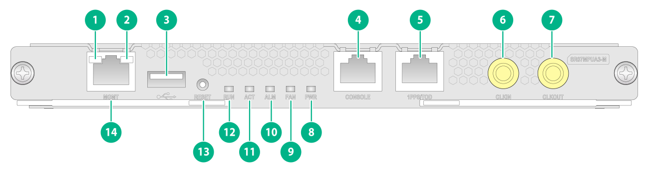
SR07MPUA3-M
View
Figure2-1 SR07MPUA3-M view
|
(1) Management Ethernet port LED (LINK). For the LED description, see Table2-1. |
(2) Management Ethernet port LED (ACT). For the LED description, see Table2-1. |
|
(3) USB 2.0 port |
(4) Console port |
|
(5) High-precision time synchronization port (input port by default) |
(6) SMB coaxial clock input port |
|
(7) SMB coaxial clock output port |
(8) Power supply status LED. For the LED description, see Table2-2. |
|
(9) Fan tray status LED. For the LED description, see Table2-3. |
(10) MPU alarm status LED. For the LED description, see Table2-4. |
|
(11) MPU active/standby LED. For the LED description, see Table2-5. |
(12) MPU status LED. For the LED description, see Table2-6. |
|
(13) System reset button |
(14) Management Ethernet port (1000Base-T) |
LEDs
Table2-1 Management Ethernet port LED description
|
LED mark |
Description |
|
|
LINK (green) |
ACT (yellow) |
|
|
Steady on |
Flashing |
A link is present, and the port is sending or receiving data. |
|
Steady on |
Off |
A link is present, but the port is not sending or receiving data. |
|
Off |
Off |
No link is present on the port. |
Table2-2 Power supply status LED description
|
LED mark |
Status |
Description |
|
PWR |
Steady green |
All power supplies in the chassis are operating correctly. |
|
Steady red |
A minimum of one power supply in the chassis does not have power output, because the power supply is faulty, the power supply is not powered on, the power cable is faulty, or the external power supply system has a power outage. |
|
|
Off |
The following are the possible causes: · No power supplies exist in the chassis. · No power supply in the chassis has power output, because the power supplies are faulty, the power supplies are not powered on, the power cables are faulty, or the external power supply system has a power outage. |
Table2-3 Fan tray status LED description
|
LED mark |
Status |
Description |
|
FAN |
Steady green |
All fan trays are operating correctly. |
|
Steady red |
The following are the possible causes: · One or more fans in a fan tray have failed. · One or more fan trays are not installed securely. |
|
|
Off |
No fan trays are powered on. |
Table2-4 MPU alarm status LED description
|
LED mark |
Status |
Description |
|
ALM |
Steady on |
The following are the possible causes: · The MPU is starting up. · The MPU is faulty. |
|
Flashing (0.25 Hz) |
The MPU temperature is abnormal. The temperature has exceeded the upper warning temperature threshold or dropped below the lower temperature threshold. |
|
|
Off |
The following are the possible causes: · The MPU is operating correctly. · The MPU is not powered on. |
Table2-5 MPU active/standby LED description
|
LED mark |
Status |
Description |
|
ACT |
Steady on |
The MPU is in active state. |
|
Off |
The following are the possible causes: · The MPU is in standby state. · The MPU has failed. To identify the failure, see the MPU status LED description. |
Table2-6 MPU status LED description
|
LED mark |
Status |
Description |
|
RUN |
Flashing (0.5 Hz) |
The MPU is operating correctly. |
|
Fast flashing (4 Hz) |
The MPU is starting up. |
|
|
Steady on |
The MPU is faulty. |
|
|
Off |
The MPU is not powered on. |
Ports
Console port
The console port can be connected to a computer for system debugging, configuration, maintenance, management, and host software loading.
Table2-7 Console port specifications
|
Item |
Description |
|
Connector type |
RJ-45 |
|
Compliant standard |
Asynchronous EIA/TIA-232 |
|
Transmission baud rate |
≤ 115200 bps. The default value is 9600 bps. |
|
Transmission medium and max transmission distance |
Common asynchronous serial interface cable, with a maximum transmission distance of 15 m (49.21 ft) |
|
Services |
Connects to the serial port on a local PC running a terminal emulation program. |
Management Ethernet port
You can connect a management Ethernet port to a computer for router program loading and router debugging, or a remote NMS for remote management.
Table2-8 Management Ethernet port specifications
|
Item |
Description |
|
Connector type |
RJ-45 |
|
Port quantity |
1 |
|
Transmission baud rate |
1000 Mbps, full duplex |
|
Transmission medium and max transmission distance |
Category-5 or above twisted pair cable, with a transmission distance of 100 m (328.08 ft) |
|
Services |
For router software upgrade and network management |
USB port
USB ports can connect multiple types of devices and provide a higher data transfer rate than common parallel interfaces and serial interfaces.
Table2-9 USB port specifications
|
Item |
Description |
|
Connector type |
USB A |
|
Compliant standard |
USB 2.0 |
|
Services |
External storage media |
|
|
NOTE: Extension cables are not supported. |
SMB coaxial clock input/output port
SMB coaxial clock ports provide input or output clock references at 2.048 Mbps (2.048 MHz). You can set the data rate mode or frequency mode through the DIP switches on the panel. The MPU has two SMB coaxial clock ports. One is an input port and the other is an output port.
Table2-10 SMB coaxial clock input/output port specifications
|
Item |
Description |
|
Connector type |
SMB coaxial |
|
Compliant standard |
GJB681 |
|
Transmission baud rate |
2.048 Mbps |
|
Transmission medium |
75-ohm coaxial cable |
|
Services |
Sends and receives 2.048 MHz clocks and 2.048 Mbps signals to synchronize the clocks of the router and other devices, such as routers and the terminals. |
High-precision time synchronization port
Table2-11 High-precision time synchronization port specifications
|
Item |
Description |
|
Connector type |
RJ-45 |
|
Compliant standard |
QB-B-016-2010 |
|
Transmission baud rate |
9600 bps |
|
Transmission medium |
Category-5 or above twisted pair cable |
|
Services |
You can configure the port as an input port or output port at the CLI. Synchronizes the clocks of the router and other devices, such as GPS receivers and terminals. |
Technical specifications
Table2-12 Technical specifications
|
Item |
Description |
|
Dimensions (H × W × D) |
22 × 214 × 262 mm (0.87 × 8.43 × 10.32 in) |
|
Weight |
1.20 kg (2.65 lb) |
|
Maximum power consumption |
53 W |
|
Power consumption (with typical configuration) |
48 W |
|
Minimum power consumption |
46 W |
|
Operating temperature |
0°C to 45°C (32°F to 113°F) |
|
SDRAM |
2 × 8GB |
Service routing and forwarding processing modules
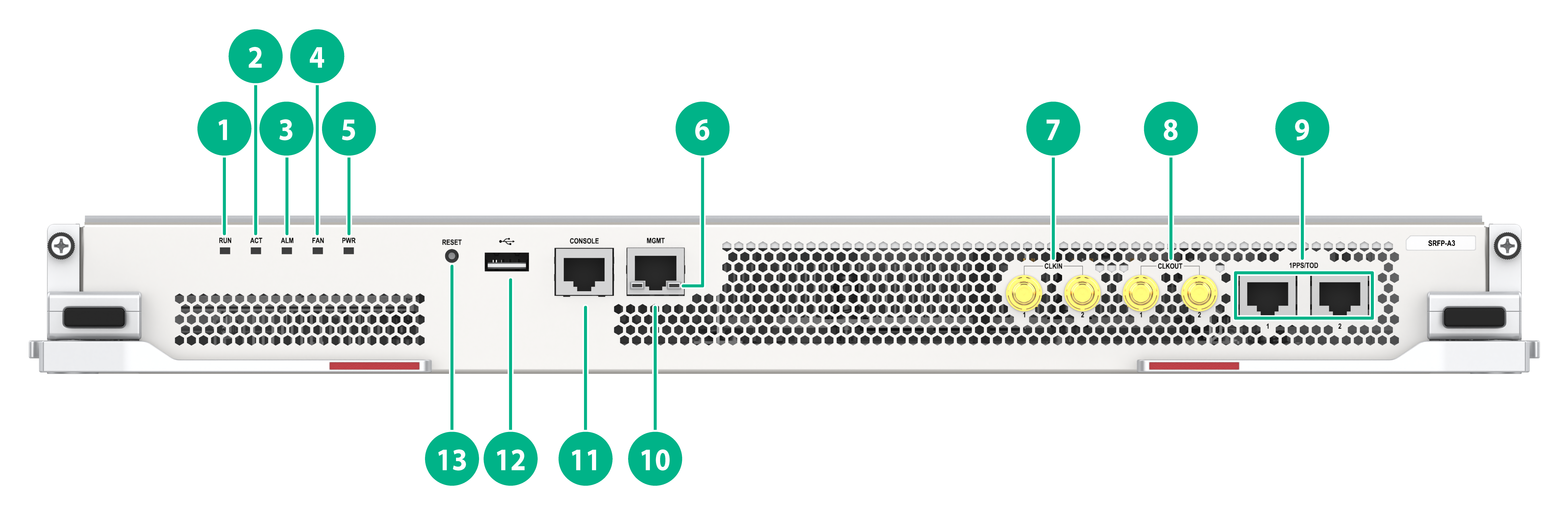
SRFP-A3
View
Figure2-2 SRFP-A3 view
|
(1) Service routing and forwarding processing module status LED. For the LED description, see Table2-13. |
(2) Service routing and forwarding processing module active/standby LED. For the LED description, see Table2-14. |
|
(3) Service routing and forwarding processing module alarm status LED. For the LED description, see Table2-15. |
(4) Fan tray status LED. For the LED description, see Table2-16. |
|
(5) Power supply status LED. For the LED description, see Table2-17. |
(6) Management Ethernet port LED (ACT). For the LED description, see Table2-18. |
|
(7) SMB coaxial clock input ports (2 in total) |
(8) SMB coaxial clock output ports (2 in total) |
|
(9) High-precision time synchronization port (Both are input ports by default. When both ports are input ports, only port 1 takes effect.) |
(10) Management Ethernet port (1000Base-T) |
|
(11) Console port |
(12) USB 2.0 port |
|
(13) System reset button |
|
LEDs
Table2-13 Service routing and forwarding processing module status LED
|
LED mark |
Status |
Description |
|
RUN |
Flashing (0.5 Hz) |
The service routing and forwarding processing module is operating correctly. |
|
Fast flashing (4 Hz) |
The service routing and forwarding processing module is starting up. |
|
|
Steady on |
The service routing and forwarding processing module is faulty. |
|
|
Off |
The service routing and forwarding processing module is not powered on. |
Table2-14 Service routing and forwarding processing module active/standby LED description
|
LED mark |
Status |
Description |
|
ACT |
Steady on |
The service routing and forwarding processing module is in active state. |
|
Off |
The following are the possible causes: · The service routing and forwarding processing module is in standby state. · The service routing and forwarding processing module has failed. To identify the failure, see the card status LED description. |
Table2-15 Service routing and forwarding processing module alarm status LED description
|
LED mark |
Status |
Description |
|
ALM |
Steady on |
The following are the possible causes: · The service routing and forwarding processing module is starting up. · The service routing and forwarding processing module is faulty. |
|
Flashing (0.25 Hz) |
The service routing and forwarding processing module temperature is abnormal. The temperature has exceeded the upper warning temperature threshold or dropped below the lower temperature threshold. |
|
|
Off |
The following are the possible causes: · The service routing and forwarding processing module is operating correctly. · The service routing and forwarding processing module is not powered on. |
Table2-16 Fan tray status LED description
|
LED mark |
Status |
Description |
|
FAN |
Steady green |
All fan trays are operating correctly. |
|
Steady red |
The following are the possible causes: · One or more fans in a fan tray have failed. · One or more fan trays are not installed securely. |
|
|
Off |
No fan trays are powered on. |
Table2-17 Power supply status LED description
|
LED mark |
Status |
Description |
|
PWR |
Steady green |
All power supplies in the chassis are operating correctly. |
|
Steady red |
A minimum of one power supply in the chassis does not have power output, because the power supply is faulty, the power supply is not powered on, the power cable is faulty, or the external power supply system has a power outage. |
|
|
Off |
The following are the possible causes: · No power supplies exist in the chassis. · No power supply in the chassis has power output, because the power supplies are faulty, the power supplies are not powered on, the power cables are faulty, or the external power supply system has a power outage. |
Table2-18 Management Ethernet port LED description
|
LED mark |
Description |
|
|
LINK (green) |
ACT (yellow) |
|
|
Steady on |
Flashing |
A link is present, and the port is sending or receiving data. |
|
Steady on |
Off |
A link is present, but the port is not sending or receiving data. |
|
Off |
Off |
No link is present on the port. |
Ports
Console port
The console port can be connected to a computer for system debugging, configuration, maintenance, management, and host software loading.
Table2-19 Console port specifications
|
Item |
Description |
|
Connector type |
RJ-45 |
|
Compliant standard |
Asynchronous EIA/TIA-232 |
|
Transmission baud rate |
≤ 115200 bps. The default value is 9600 bps. |
|
Transmission medium and max transmission distance |
Common asynchronous serial interface cable, with a maximum transmission distance of 15 m (49.21 ft) |
|
Services |
Connects to the serial port on a local PC running a terminal emulation program. |
Management Ethernet port
You can connect a management Ethernet port to a computer for router program loading and router debugging, or a remote NMS for remote management.
Table2-20 Management Ethernet port specifications
|
Item |
Description |
|
Connector type |
RJ-45 |
|
Port quantity |
1 |
|
Transmission baud rate |
1000 Mbps, full duplex |
|
Transmission medium and max transmission distance |
Category-5 or above twisted pair cable, with a transmission distance of 100 m (328.08 ft) |
|
Services |
For router software upgrade and network management |
USB port
USB ports can connect multiple types of devices and provide a higher data transfer rate than common parallel interfaces and serial interfaces.
Table2-21 USB port specifications
|
Item |
Description |
|
Connector type |
USB A |
|
Compliant standard |
USB 2.0 |
|
Services |
External storage media |
|
|
NOTE: Extension cables are not supported. |
SMB coaxial clock input/output port
SMB coaxial clock ports provide input or output clock references at 2.048 Mbps (2.048 MHz). You can set the data rate mode or frequency mode through the DIP switches on the panel. The service routing and forwarding processing module has four SMB coaxial clock ports. Two of them are input ports and two are output ports.
Table2-22 SMB coaxial clock input/output port specifications
|
Item |
Description |
|
Connector type |
SMB coaxial |
|
Compliant standard |
GJB681 |
|
Transmission baud rate |
2.048 Mbps |
|
Transmission medium |
75-ohm coaxial cable |
|
Services |
Sends and receives 2.048 MHz clocks and 2.048 Mbps signals to synchronize the clocks of the router and other devices, such as routers and the terminals. |
High-precision time synchronization port
Table2-23 High-precision time synchronization port specifications
|
Item |
Description |
|
Connector type |
RJ-45 |
|
Compliant standard |
QB-B-016-2010 |
|
Transmission baud rate |
9600 bps |
|
Transmission medium |
Category-5 or above twisted pair cable |
|
Services |
You can configure the port as an input port or output port at the CLI. Synchronizes the clocks of the router and other devices, such as GPS receivers and terminals. |
Technical specifications
Table2-24 Technical specifications
|
Item |
Description |
|
Dimensions (H × W × D) |
44 × 429 × 264 mm (1.73 × 16.89 × 10.39 in) |
|
Weight |
5.05 kg (11.13 lb) |
|
Maximum power consumption |
211 W |
|
Power consumption (with typical configuration) |
195 W |
|
Minimum power consumption |
159 W |
|
Operating temperature |
0°C to 45°C (32°F to 113°F) |
|
SDRAM |
2 × 8GB |
Compatibility information
Table2-25 Compatibility matrix between service routing and forwarding processing modules and routers
|
Service routing and forwarding processing module model |
CR16000-M8 |
CR16000-M16 |
|
SRFP-A3 |
√ (only in slots 10 and 11) |
√ (only in slots 18 and 19) |
Interface modules
The router supports various interface modules that provide different types and numbers of ports.
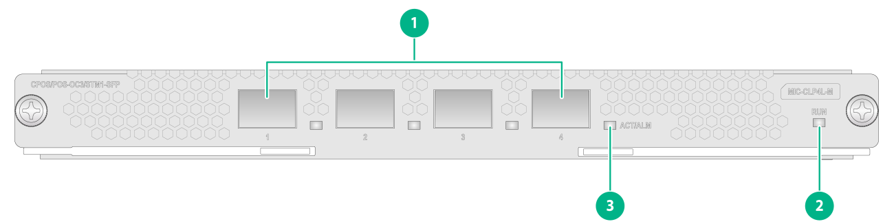
MIC-CLP4L-M
View
Figure2-3 MIC-CLP4L-M view
|
(1) CPOS-OC-3/STM-1-SFP fiber ports (4 in total) |
(2) Interface module status LED. For the LED description, see Table2-26. |
|
(3) Port LED. For the LED description, see Table2-27. |
|
LEDs
Table2-26 Interface module status LED description
|
LED mark |
Status |
Description |
|
RUN |
Flashing (0.5 Hz) |
The interface module is operating correctly. |
|
Fast flashing (4 Hz) |
The interface module is loading software. If the interface module stays in this state, it indicates that software loading has failed. |
|
|
Steady on |
The interface module is faulty. |
|
|
Off |
The interface module is faulty or is not powered on. |
Table2-27 Port LED description
|
LED mark |
Status |
Description |
|
ACT/ALM |
Flashing green |
The port is sending or receiving data. |
|
Steady green |
A link is present, but the port is not receiving or sending data. |
|
|
Steady red |
An alarm has occurred. |
|
|
Off |
No link is present on the port. |
Ports
Table2-28 Port specifications
|
Interface module model |
Description |
Connector type |
Port quantity |
Port transmission speed |
|
MIC-CLP4L-M |
4-port OC-3/STM-1(155M) channelized POS optical interface module |
LC |
4 |
155 Mbps (OC-3c/STM-1c) |
Technical specifications
Table2-29 Technical specifications
|
Item |
Description |
|
Dimensions (H × W × D) |
22 × 214 × 262 mm (0.87 × 8.43 × 10.32 in) |
|
Weight |
1.10 kg (2.43 lb) |
|
Maximum power consumption |
35 W |
|
Power consumption (with typical configuration) |
34 W |
|
Minimum power consumption |
32 W |
|
Operating temperature |
0°C to 45°C (32°F to 113°F) |
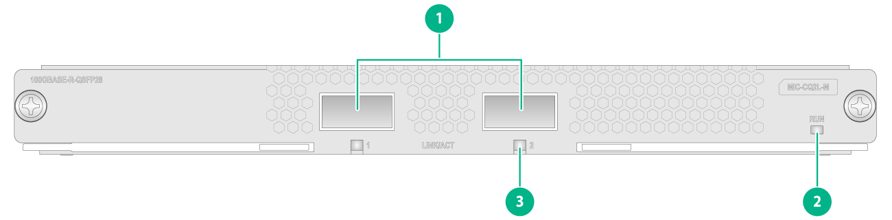
MIC-CQ1L-M
View
Figure2-4 MIC-CQ1L-M view

|
(1) 100GBASE-R-QSFP28 fiber port (1 in total) |
(2) Interface module status LED. For the LED description, see Table2-30. |
|
(3) QSFP28 port LED. For the LED description, see Table2-31. |
|
LEDs
Table2-30 Interface module status LED description
|
LED mark |
Status |
Description |
|
RUN |
Flashing (0.5 Hz) |
The interface module is operating correctly. |
|
Fast flashing (4 Hz) |
The interface module is loading software. If the interface module stays in this state, it indicates that software loading has failed. |
|
|
Steady on |
The interface module is faulty. |
|
|
Off |
The interface module is faulty or is not powered on. |
Table2-31 QSFP28 port LED description
|
LED mark |
Status |
Description |
|
LINK/ACT |
Flashing green |
The QSFP28 port is sending or receiving data. |
|
Steady green |
A link is present on the QSFP28 port. |
|
|
Off |
No link is present on the QSFP28 port. |
Ports
Table2-32 Port specifications
|
Interface module model |
Description |
Connector type |
Port quantity |
Port transmission speed |
|
MIC-CQ1L-M |
1-port 100GE optical interface module |
LC |
1 |
· 100 Gbps · 50 Gbps |
Technical specifications
Table2-33 Technical specifications
|
Item |
Description |
|
Dimensions (H × W × D) |
22 × 214 × 262 mm (0.87 × 8.43 × 10.32 in) |
|
Weight |
1.05 kg (2.31 lb) |
|
Maximum power consumption |
18 W |
|
Power consumption (with typical configuration) |
17 W |
|
Minimum power consumption |
16 W |
|
Operating temperature |
0°C to 45°C (32°F to 113°F) |
MIC-CQ1LF-M
View
Figure2-5 MIC-CQ1LF-M view

|
(1) 100GBASE-R-QSFP28 fiber port (1 in total) |
(2) Interface module status LED. For the LED description, see Table2-34. |
|
(3) QSFP28 port LED. For the LED description, see Table2-35. |
|
LEDs
Table2-34 Interface module status LED description
|
LED mark |
Status |
Description |
|
RUN |
Flashing (0.5 Hz) |
The interface module is operating correctly. |
|
Fast flashing (4 Hz) |
The interface module is loading software. If the interface module stays in this state, it indicates that software loading has failed. |
|
|
Steady on |
The interface module is faulty. |
|
|
Off |
The interface module is faulty or is not powered on. |
Table2-35 QSFP28 port LED description
|
LED mark |
Status |
Description |
|
LINK/ACT |
Flashing green |
The QSFP28 port is sending or receiving data. |
|
Steady green |
A link is present on the QSFP28 port. |
|
|
Off |
No link is present on the QSFP28 port. |
Ports
Table2-36 Port specifications
|
Interface module model |
Description |
Connector type |
Port quantity |
Port transmission speed |
|
MIC-CQ1LF-M |
1-port 100GE flexible optical interface module |
LC |
1 |
100 Gbps |
Technical specifications
Table2-37 Technical specifications
|
Item |
Description |
|
Dimensions (H × W × D) |
22 × 214 × 262 mm (0.87 × 8.43 × 10.32 in) |
|
Weight |
1.10 kg (2.43 lb) |
|
Maximum power consumption |
50 W |
|
Power consumption (with typical configuration) |
47 W |
|
Minimum power consumption |
38 W |
|
Operating temperature |
0°C to 45°C (32°F to 113°F) |
MIC-CQ2L-M
View
Figure2-6 MIC-CQ2L-M view
|
(1) 100GBASE-R-QSFP28 fiber ports (2 in total) |
(2) Interface module status LED. For the LED description, see Table2-38. |
|
(3) QSFP28 port LED. For the LED description, see Table2-39. |
|
LEDs
Table2-38 Interface module status LED description
|
LED mark |
Status |
Description |
|
RUN |
Flashing (0.5 Hz) |
The interface module is operating correctly. |
|
Fast flashing (4 Hz) |
The interface module is loading software. If the interface module stays in this state, it indicates that software loading has failed. |
|
|
Steady on |
The interface module is faulty. |
|
|
Off |
The interface module is faulty or is not powered on. |
Table2-39 QSFP28 port LED description
|
LED mark |
Status |
Description |
|
LINK/ACT |
Flashing green |
The QSFP28 port is sending or receiving data. |
|
Steady green |
A link is present on the QSFP28 port. |
|
|
Off |
No link is present on the QSFP28 port. |
Ports
Table2-40 Port specifications
|
Interface module model |
Description |
Connector type |
Port quantity |
Port transmission speed |
|
MIC-CQ2L-M |
2-port 100GE optical interface module |
LC |
2 |
· 100 Gbps · 50 Gbps |
Technical specifications
Table2-41 Technical specifications
|
Item |
Description |
|
Dimensions (H × W × D) |
22 × 214 × 262 mm (0.87 × 8.43 × 10.32 in) |
|
Weight |
1.10 kg (2.43 lb) |
|
Maximum power consumption |
28 W |
|
Power consumption (with typical configuration) |
26.8 W |
|
Minimum power consumption |
26 W |
|
Operating temperature |
0°C to 45°C (32°F to 113°F) |
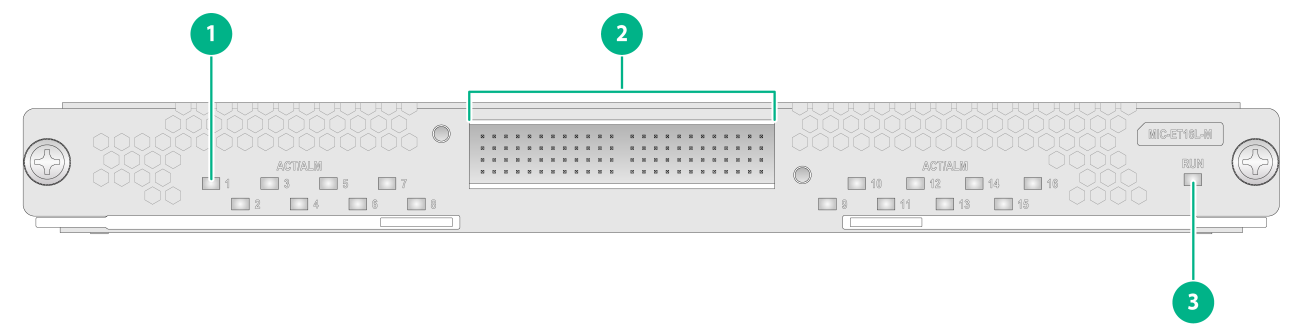
MIC-ET16L-M
View
Figure2-7 MIC-ET16L-M view
|
(1) Port LED. For the LED description, see Table2-43. |
(2) E1-HM96 copper ports (16 in total) |
|
(3) Interface module status LED. For the LED description, see Table2-42. |
|
LEDs
Table2-42 Interface module status LED description
|
LED mark |
Status |
Description |
|
RUN |
Flashing (0.5 Hz) |
The interface module is operating correctly. |
|
Fast flashing (4 Hz) |
The interface module is loading software. If the interface module stays in this state, it indicates that software loading has failed. |
|
|
Steady on |
The interface module is faulty. |
|
|
Off |
The interface module is faulty or is not powered on. |
Table2-43 Port LED description
|
LED mark |
Status |
Description |
|
ACT/ALM |
Flashing green |
The port is sending or receiving data. |
|
Steady green |
A link is present, but the port is not receiving or sending data. |
|
|
Steady red |
An alarm has occurred. |
|
|
Off |
No link is present on the port. |
Ports and cables
Table2-44 Port specifications
|
Interface module model |
Description |
Connector type |
Port quantity |
Port transmission speed |
|
MIC-ET16L-M |
16-port E1 copper interface module |
HM96 male |
16 |
2.048 Mbps (E1) |
The MIC-ET16L-M interface module provides HM96 male connector with E1 port. Use different cables for conversion from HM96 to RJ-45, BNC, or SMB as needed.
|
Model |
Description |
|
SR0M7CAB1 |
HM96 E1 cable, 75 ohm, BNC, 3 m (9.84 ft) |
|
SR0M7CAB2 |
HM96 E1 cable, 120 ohm, RJ45, 3 m (9.84 ft) |
|
SR0M7CAB3 |
HM96 E1 cable, 75 ohm, SMB, 3 m (9.84 ft) |
Technical specifications
Table2-46 Technical specifications
|
Item |
Description |
|
Dimensions (H × W × D) |
22 × 214 × 262 mm (0.87 × 8.43 × 10.32 in) |
|
Weight |
1.10 kg (2.43 lb) |
|
Maximum power consumption |
31 W |
|
Power consumption (with typical configuration) |
30.5 W |
|
Minimum power consumption |
29 W |
|
Operating temperature |
0°C to 45°C (32°F to 113°F) |
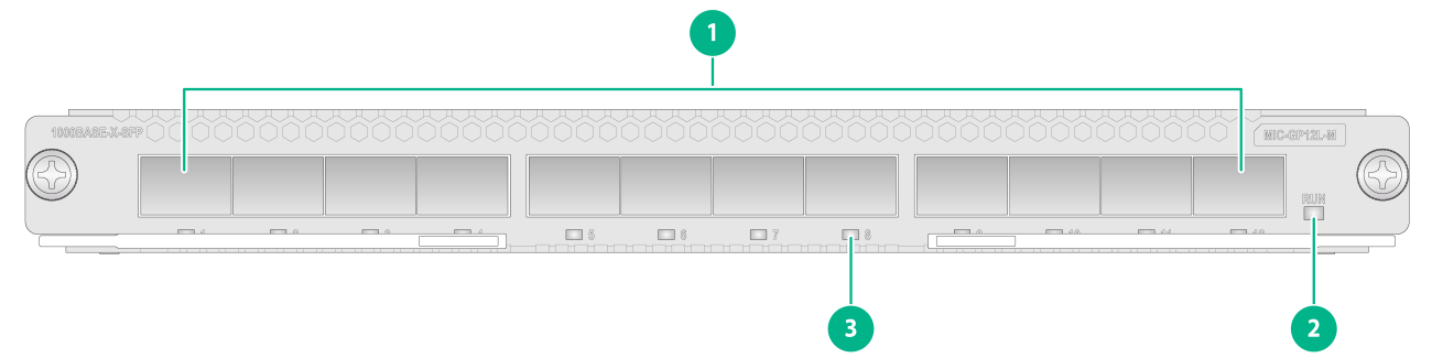
MIC-GP12L-M
View
Figure2-8 MIC-GP12L-M view
|
(1) 1000BASE-X-SFP fiber ports (12 in total) |
(2) Interface module status LED. For the LED description, see Table2-47. |
|
(3) SFP port LED. For the LED description, see Table2-48. |
|
LEDs
Table2-47 Interface module status LED description
|
LED mark |
Status |
Description |
|
RUN |
Flashing (0.5 Hz) |
The interface module is operating correctly. |
|
Fast flashing (4 Hz) |
The interface module is loading software. If the interface module stays in this state, it indicates that software loading has failed. |
|
|
Steady on |
The interface module is faulty. |
|
|
Off |
The interface module is faulty or is not powered on. |
Table2-48 SFP port LED description
|
LED |
Status |
Description |
|
SFP port LED |
Flashing |
The SFP port is sending or receiving data. |
|
On |
A link is present on the SFP port. |
|
|
Off |
No link is present on the SFP port. |
Ports
Table2-49 Port specifications
|
Interface module model |
Description |
Connector type |
Port quantity |
Port transmission speed |
|
MIC-GP12L-M |
12-port GE optical interface module |
LC |
12 |
· 10 Mbps · 100 Mbps · 1000 Mbps |
Technical specifications
Table2-50 Technical specifications
|
Item |
Description |
|
Dimensions (H × W × D) |
22 × 214 × 262 mm (0.87 × 8.43 × 10.32 in) |
|
Weight |
1.20 kg (2.65 lb) |
|
Maximum power consumption |
38 W |
|
Power consumption (with typical configuration) |
37 W |
|
Minimum power consumption |
36 W |
|
Operating temperature |
0°C to 45°C (32°F to 113°F) |
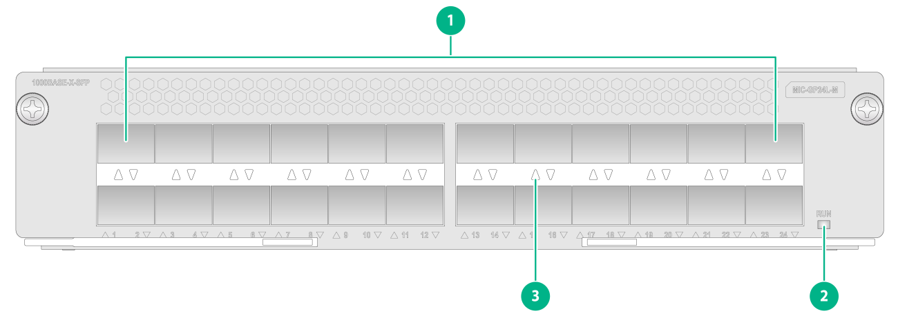
MIC-GP24L-M
View
Figure2-9 MIC-GP24L-M view
|
(1) 1000BASE-X-SFP fiber ports (24 in total) |
(2) Interface module status LED. For the LED description, see Table2-51. |
|
(3) SFP port LED. For the LED description, see Table2-52. |
|
LEDs
Table2-51 Interface module status LED description
|
LED mark |
Status |
Description |
|
RUN |
Flashing (0.5 Hz) |
The interface module is operating correctly. |
|
Fast flashing (4 Hz) |
The interface module is loading software. If the interface module stays in this state, it indicates that software loading has failed. |
|
|
On |
The interface module is faulty. |
|
|
Off |
The interface module is faulty or is not powered on. |
Table2-52 SFP port LED description
|
LED |
Status |
Description |
|
SFP port LED |
Flashing |
The SFP port is sending or receiving data. |
|
Steady on |
A link is present on the SFP port. |
|
|
Off |
No link is present on the SFP port. |
Ports
Table2-53 Port specifications
|
Interface module model |
Description |
Connector type |
Port quantity |
Port transmission speed |
|
MIC-GP24L-M |
24-port GE optical interface module |
LC |
24 |
· 10 Mbps · 100 Mbps · 1000 Mbps |
Technical specifications
Table2-54 Technical specifications
|
Item |
Description |
|
Dimensions (H × W × D) |
44 × 214 × 262 mm (1.73 × 8.43 × 10.32 in) |
|
Weight |
1.70 kg (3.75 lb) |
|
Maximum power consumption |
42 W |
|
Power consumption (with typical configuration) |
41.5 W |
|
Minimum power consumption |
29 W |
|
Operating temperature |
0°C to 45°C (32°F to 113°F) |
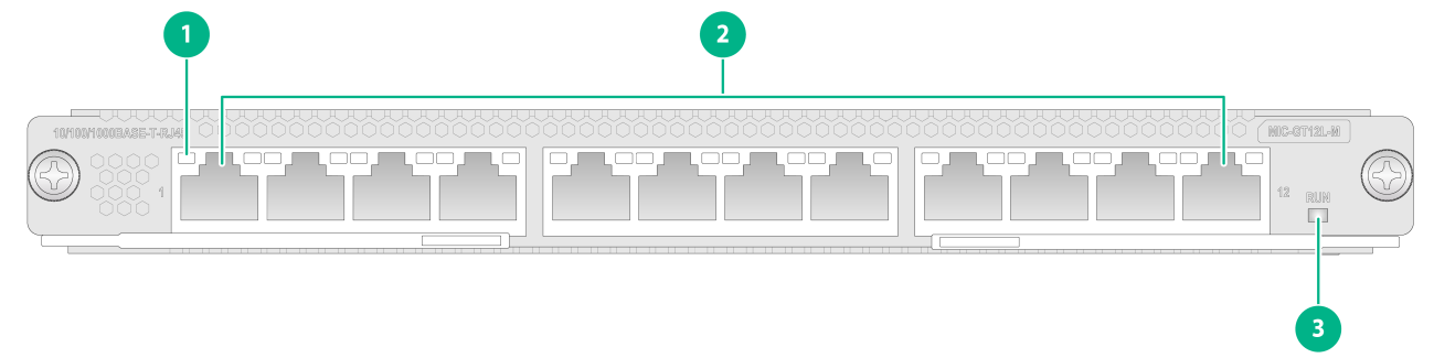
MIC-GT12L-M
View
Figure2-10 MIC-GT12L-M view
|
(1) RJ-45 Ethernet port LED. For the LED description, see Table2-56. |
(2) 1000BASE-X-SFP fiber ports (12 in total) |
|
(3) Interface module status LED. For the LED description, see Table2-55. |
|
LEDs
Table2-55 Interface module status LED description
|
LED mark |
Status |
Description |
|
RUN |
Flashing (0.5 Hz) |
The interface module is operating correctly. |
|
Fast flashing (4 Hz) |
The interface module is loading software. If the interface module stays in this state, it indicates that software loading has failed. |
|
|
Steady on |
The interface module is faulty. |
|
|
Off |
The interface module is faulty or is not powered on. |
Table2-56 RJ-45 Ethernet port LED description
|
LED |
Status |
Description |
|
RJ-45 Ethernet port LED |
Flashing |
The port is sending or receiving data. |
|
On |
A link is present on the port. |
|
|
Off |
No link is present on the port. |
Ports
Table2-57 Port specifications
|
Interface module model |
Description |
Connector type |
Port quantity |
Port transmission speed |
|
MIC-GT12L-M |
12-port GE copper interface module |
RJ-45 |
12 |
· 10 Mbps · 100 Mbps · 1000 Mbps |
Technical specifications
Table2-58 Technical specifications
|
Item |
Description |
|
Dimensions (H × W × D) |
22 × 214 × 262 mm (0.87 × 8.43 × 10.32 in) |
|
Weight |
1.28 kg (2.82 lb) |
|
Maximum power consumption |
32 W |
|
Power consumption (with typical configuration) |
31.6 W |
|
Minimum power consumption |
30 W |
|
Operating temperature |
0°C to 45°C (32°F to 113°F) |
MIC-PSP4L-M
View
Figure2-11 MIC-PSP4L-M view
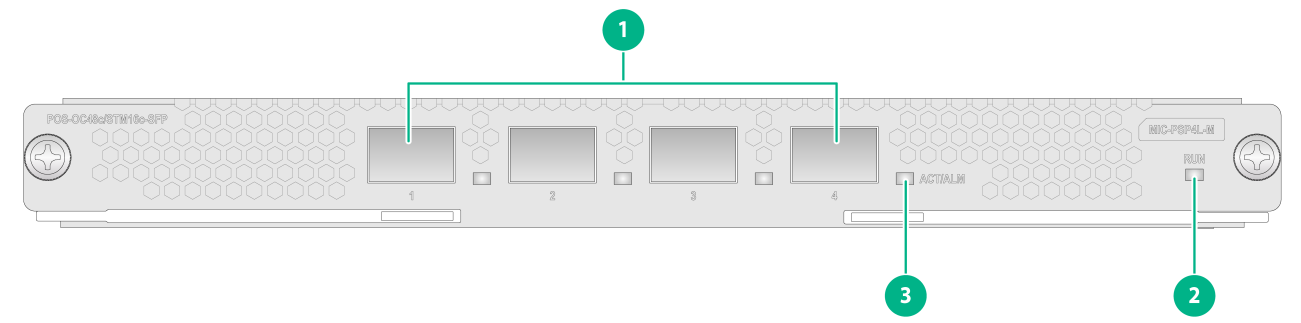
|
(1) OC-48c/STM-16c POS fiber ports (4 in total) |
(2) Interface module status LED. For the LED description, see Table2-59. |
|
(3) Port LED. For the LED description, see Table2-60. |
|
LEDs
Table2-59 Interface module status LED description
|
LED mark |
Status |
Description |
|
RUN |
Flashing (0.5 Hz) |
The interface module is operating correctly. |
|
Fast flashing (4 Hz) |
The interface module is loading software. If the interface module stays in this state, it indicates that software loading has failed. |
|
|
Steady on |
The interface module is faulty. |
|
|
Off |
The interface module is faulty or is not powered on. |
Table2-60 Port LED description
|
LED mark |
Status |
Description |
|
ACT/ALM |
Flashing green |
The port is sending or receiving data. |
|
Steady green |
A link is present, but the port is not receiving or sending data. |
|
|
Steady red |
An alarm has occurred. |
|
|
Off |
No link is present on the port. |
Ports
Table2-61 Port specifications
|
Interface module model |
Description |
Connector type |
Port quantity |
Port transmission speed |
|
MIC-PSP4L-M |
4-port OC-48c/STM-16c(2.5G) POS optical interface module |
LC |
4 |
2.5 Gbps (OC-48c/STM-16c) |
Technical specifications
Table2-62 Technical specifications
|
Item |
Description |
|
Dimensions (H × W × D) |
22 × 214 × 262 mm (0.87 × 8.43 × 10.32 in) |
|
Weight |
1.10 kg (2.43 lb) |
|
Maximum power consumption |
50 W |
|
Power consumption (with typical configuration) |
48 W |
|
Minimum power consumption |
40 W |
|
Operating temperature |
0°C to 45°C (32°F to 113°F) |
MIC-SEC-M
View
Figure2-12 MIC-SEC-M view
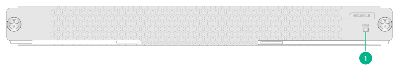
|
(1) Card status LED. For the LED description, see Table2-63. |
LEDs
Table2-63 Card LED description
|
LED mark |
Status |
Description |
|
RUN |
Steady green |
The card is faulty. |
|
Off |
The card is faulty or is not in position. |
|
|
Flashing green (about once per second) |
The card is operating correctly. |
|
|
Fast flashing green |
The card is starting up. If the LED keeps fast flashing, card registration has failed. |
Ports
Table2-64 Port specifications
|
Interface module model |
Description |
Connector type |
Port quantity |
Port transmission speed |
|
MIC-SEC-M |
Network data encryption service processing interface module (MIC-M) |
N/A |
N/A |
N/A |
Technical specifications
Table2-65 Technical specifications
|
Item |
Description |
|
Dimensions (H × W × D) |
22 × 214 × 262 mm (0.87 × 8.43 × 10.32 in) |
|
Weight |
1.10 kg (2.43 lb) |
|
Maximum power consumption |
50 W |
|
Power consumption (with typical configuration) |
48 W |
|
Minimum power consumption |
40 W |
|
Operating temperature |
0°C to 45°C (32°F to 113°F) |
MIC-SP4L-M
View
Figure2-13 MIC-SP4L-M view
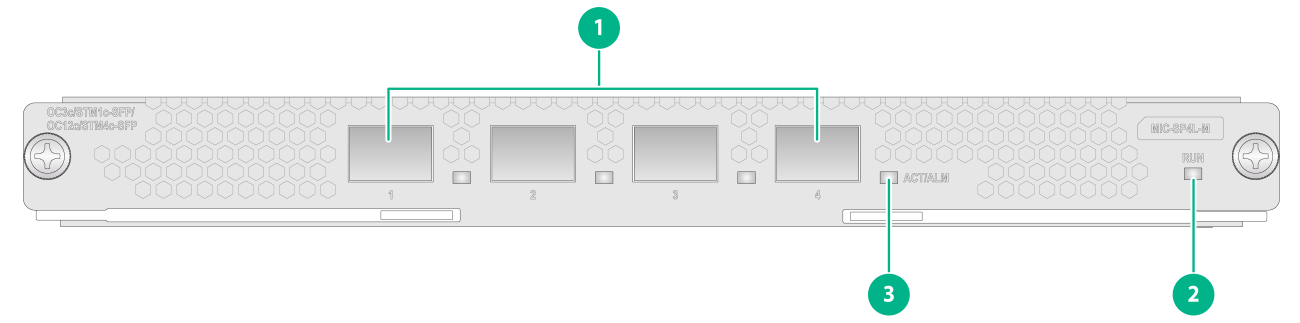
|
(1) OC-3c/STM-1c POS/ATM fiber ports (4 in total) or OC-12c/STM-4c POS/ATM fiber port (port 1) |
(2) Interface module status LED. For the LED description, see Table2-66. |
|
(3) Port LED. For the LED description, see Table2-67. |
|
LEDs
Table2-66 Interface module status LED description
|
LED mark |
Status |
Description |
|
RUN |
Flashing (0.5 Hz) |
The interface module is operating correctly. |
|
Fast flashing (4 Hz) |
The interface module is loading software. If the interface module stays in this state, it indicates that software loading has failed. |
|
|
Steady on |
The interface module is faulty. |
|
|
Off |
The interface module is faulty or is not powered on. |
Table2-67 Port LED description
|
LED mark |
Status |
Description |
|
ACT/ALM |
Flashing green |
The port is sending or receiving data. |
|
Steady green |
A link is present, but the port is not receiving or sending data. |
|
|
Steady red |
An alarm has occurred. |
|
|
Off |
No link is present on the port. |
Ports
Table2-68 Port specifications
|
Interface module model |
Description |
Connector type |
Port quantity |
Port transmission speed |
|
MIC-SP4L-M |
4-port OC-3c/STM-1c(155M) POS/ATM or 1-port OC-12c/STM-4c(622M) POS/ATM optical interface module (The interface module does not support switching to the ATM mode.) |
LC |
4 |
155 Mbps (OC-3c/STM-1c) |
|
1 |
622 Mbps (OC-12c/STM-4c) |
Technical specifications
Table2-69 Technical specifications
|
Item |
Description |
|
Dimensions (H × W × D) |
22 × 214 × 262 mm (0.87 × 8.43 × 10.32 in) |
|
Weight |
1.10 kg (2.43 lb) |
|
Maximum power consumption |
35 W |
|
Power consumption (with typical configuration) |
34 W |
|
Minimum power consumption |
32 W |
|
Operating temperature |
0°C to 45°C (32°F to 113°F) |
MIC-TCP8L-M
View
Figure2-14 MIC-TCP8L-M view
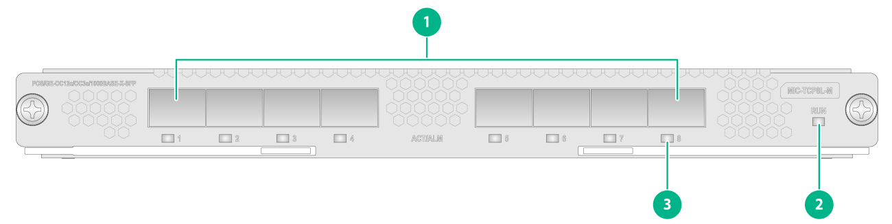
|
(1) OC-3c/OC-12c POS/GE fiber ports (8 in total) |
(2) Interface module status LED. For the LED description, see Table2-70. |
|
(3) Port LED. For the LED description, see Table2-71. |
|
LEDs
Table2-70 Interface module status LED description
|
LED mark |
Status |
Description |
|
RUN |
Flashing (0.5 Hz) |
The interface module is operating correctly. |
|
Fast flashing (4 Hz) |
The interface module is loading software. If the interface module stays in this state, it indicates that software loading has failed. |
|
|
Steady on |
The interface module is faulty. |
|
|
Off |
The interface module is faulty or is not powered on. |
Table2-71 Port LED description
|
LED mark |
Status |
Description |
|
ACT/ALM |
Flashing green |
The port is sending or receiving data. |
|
Steady green |
A link is present, but the port is not receiving or sending data. |
|
|
Steady red |
An alarm has occurred. |
|
|
Off |
No link is present on the port. |
Ports
Table2-72 Port specifications
|
Interface module model |
Description |
Connector type |
Port quantity |
Port transmission speed |
|
MIC-TCP8L-M |
8-port OC-3c/OC-12c(622M/155M) POS/GE optical interface module |
LC |
8 |
· 155 Mbps (OC-3/STM-1) · 622 Mbps (OC-12/STM-4) · 1000 Mbps |
Technical specifications
Table2-73 Technical specifications
|
Item |
Description |
|
Dimensions (H × W × D) |
22 × 214 × 262 mm (0.87 × 8.43 × 10.32 in) |
|
Weight |
1.10 kg (2.43 lb) |
|
Maximum power consumption |
45 W |
|
Power consumption (with typical configuration) |
44 W |
|
Minimum power consumption |
43 W |
|
Operating temperature |
0°C to 45°C (32°F to 113°F) |
MIC-XP4L-M
View
Figure2-15 MIC-XP4L-M view
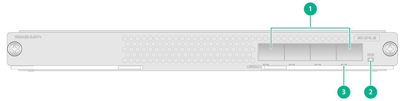
|
(1) 10GBASE-R/W-SFP+ fiber ports (4 in total) |
(2) Interface module status LED. For the LED description, see Table2-74. |
|
(3) SFP+ port LED. For the LED description, see Table2-75. |
|
LEDs
Table2-74 Interface module status LED description
|
LED mark |
Status |
Description |
|
RUN |
Flashing (0.5 Hz) |
The interface module is operating correctly. |
|
Fast flashing (4 Hz) |
The interface module is loading software. If the interface module stays in this state, it indicates that software loading has failed. |
|
|
Steady on |
The interface module is faulty. |
|
|
Off |
The interface module is faulty or is not powered on. |
Table2-75 SFP+ port LED description
|
LED mark |
Status |
Description |
|
LINK/ACT |
Flashing |
The SFP+ port is sending or receiving data. |
|
On |
A link is present on the SFP+ port. |
|
|
Off |
No link is present on the SFP+ port. |
|
|
NOTE: You can check the port speed by observing the color of the SFP+ port LED. Green indicates a speed of 10 Gbps, and yellow indicates a speed of 1000 Mbps. |
Ports
Table2-76 Port specifications
|
Interface module model |
Description |
Connector type |
Port quantity |
Port transmission speed |
|
MIC-XP4L-M |
4-port 10GE optical interface module |
LC |
4 |
· 10 Gbps · 1000 Mbps |
Technical specifications
Table2-77 Technical specifications
|
Item |
Description |
|
Dimensions (H × W × D) |
22 × 214 × 262 mm (0.87 × 8.43 × 10.32 in) |
|
Weight |
1.10 kg (2.43 lb) |
|
Maximum power consumption |
16W |
|
Power consumption (with typical configuration) |
14.4W |
|
Minimum power consumption |
14W |
|
Operating temperature |
0°C to 45°C (32°F to 113°F) |
MIC-XP10L-M
View
Figure2-16 MIC-XP10L-M view
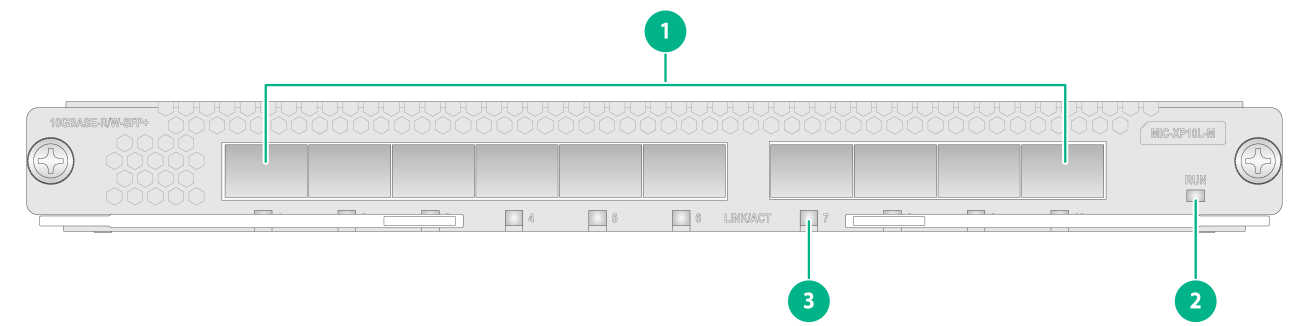
|
(1) 10GBASE-R/W-SFP+ fiber ports (10 in total) |
(2) Interface module status LED. For the LED description, see Table2-78. |
|
(3) SFP+ port LED. For the LED description, see Table2-79. |
|
LEDs
Table2-78 Interface module status LED description
|
LED mark |
Status |
Description |
|
RUN |
Flashing (0.5 Hz) |
The interface module is operating correctly. |
|
Fast flashing (4 Hz) |
The interface module is loading software. If the interface module stays in this state, it indicates that software loading has failed. |
|
|
Steady on |
The interface module is faulty. |
|
|
Off |
The interface module is faulty or is not powered on. |
Table2-79 SFP+ port LED description
|
LED mark |
Status |
Description |
|
LINK/ACT |
Flashing |
The SFP+ port is sending or receiving data. |
|
On |
A link is present on the SFP+ port. |
|
|
Off |
No link is present on the SFP+ port. |
|
|
NOTE: You can check the port speed by observing the color of the SFP+ port LED. Green indicates a speed of 10 Gbps, and yellow indicates a speed of 1000 Mbps. |
Ports
Table2-80 Port specifications
|
Interface module model |
Description |
Connector type |
Port quantity |
Port transmission speed |
|
MIC-XP10L-M |
10-port 10GE optical interface module |
LC |
10 |
· 10 Gbps · 1000 Mbps |
Technical specifications
Table2-81 Technical specifications
|
Item |
Description |
|
Dimensions (H × W × D) |
22 × 214 × 262 mm (0.87 × 8.43 × 10.32 in) |
|
Weight |
1.10 kg (2.43 lb) |
|
Maximum power consumption |
50 W |
|
Power consumption (with typical configuration) |
44 W |
|
Minimum power consumption |
35 W |
|
Operating temperature |
0°C to 45°C (32°F to 113°F) |
Compatibility information
Compatibility between interface modules and routers varies by switching fabric modules or service routing and forwarding processing modules that are installed.
Table2-82 Compatibility matrix between interface modules and routers installed with SFE-A switching fabric modules
|
Interface module model |
CR16000-M8 (SFE-A) |
CR16000-M16 (SFE-A) |
|
MIC-CLP4L-M |
√ (Up to 4 interface modules) |
√ (Up to 4 interface modules) |
|
MIC-CQ1L-M |
√ |
√ (only in slots 6 to 13) |
|
MIC-CQ1LF-M |
√ (only in slots 4 and 5) |
√ (only in slots 8 and 9) |
|
MIC-CQ2L-M |
√ (only in slots 4 and 5) |
√ (only in slots 8 and 9) |
|
MIC-ET16L-M |
√ |
√ |
|
MIC-GP12L-M |
√ |
√ |
|
MIC-GP24L-M |
√ (only in slots 4, 5, 8, and 9) |
√ (only in slots 4, 5, 8, 9, 12, 13, 16, and 17) |
|
MIC-GT12L-M |
√ |
√ |
|
MIC-PSP4L-M |
√ |
√ |
|
MIC-SEC-M |
√ |
√ |
|
MIC-SP4L-M |
√ |
√ |
|
MIC-TCP8L-M |
√ |
√ |
|
MIC-XP4L-M |
√ |
√ (only in slots 2 to 13) |
|
MIC-XP10L-M |
√ |
√ (only in slots 6 to 13) |
Table2-83 Compatibility matrix between interface modules and routers installed with SRFP-A3 service routing and forwarding processing modules
|
Interface module model |
CR16000-M8 (SRFP-A3) |
CR16000-M16 (SRFP-A3) |
|
MIC-CLP4L-M |
√ |
√ |
|
MIC-CQ1L-M |
√ |
√ (only in slots 6 to 13) |
|
MIC-CQ1LF-M |
√ (only in slots 4 and 5) |
√ (only in slots 8 and 9) |
|
MIC-CQ2L-M |
√ (only in slots 4 and 5) |
√ (only in slots 8 and 9) |
|
MIC-ET16L-M |
√ |
√ |
|
MIC-GP12L-M |
√ |
√ |
|
MIC-GP24L-M |
√ (only in slots 4, 5, 8, and 9) |
√ (only in slots 4, 5, 8, 9, 12, 13, 16, and 17) |
|
MIC-GT12L-M |
√ |
√ |
|
MIC-PSP4L-M |
√ |
√ |
|
MIC-SEC-M |
√ |
√ |
|
MIC-SP4L-M |
√ |
√ |
|
MIC-TCP8L-M |
√ |
√ |
|
MIC-XP4L-M |
√ |
√ (only in slots 2 to 13) |
|
MIC-XP10L-M |
√ |
√ (only in slots 6 to 13) |
Switching fabric modules
You can add one switching fabric module or remove the unused switching fabric module without powering off the router. The operation does not affect transmission of interface modules or service continuity.
SFE-A
The switching fabric modules are the core of the switching plane of the router. The SFE-A switching fabric module is applicable to all CR16000-M models.
View
Figure2-17 SFE-A view
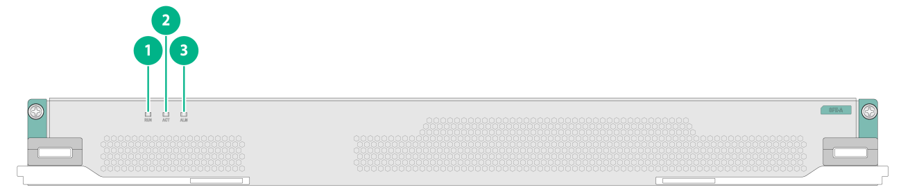
|
(1) Switching fabric module status LED. For the LED description, see Table2-84. |
(2) Switching fabric module active/standby LED. For the LED description, see Table2-85. |
|
(3) Switching fabric module alarm status LED. For the LED description, see Table2-86. |
|
LEDs
Table2-84 Switching fabric module status LED description
|
LED mark |
Status |
Description |
|
RUN |
Flashing (0.5 Hz) |
The switching fabric module is operating correctly. |
|
Fast flashing (4 Hz) |
The switching fabric module is loading software. If the switching fabric module stays in this state, it indicates that software loading has failed. |
|
|
Steady on |
The switching fabric module is faulty. |
|
|
Off |
The switching fabric module is faulty or is not powered on. |
Table2-85 Switching fabric module active/standby LED description
|
Status |
Description |
|
|
ACT |
Steady on |
The switching fabric module is in active state. |
|
Off |
The following are the possible causes: · The switching fabric module is in standby state. · The switching fabric module is not powered on. |
Table2-86 Switching fabric module alarm status LED description
|
LED mark |
Status |
Description |
|
ALM |
On |
An alarm has occurred. |
|
Flashing (0.25 Hz) |
The switching fabric module temperature is abnormal. The temperature has exceeded the upper warning temperature threshold or dropped below the lower temperature threshold. |
|
|
Off |
The following are the possible causes: · The switching fabric module is operating correctly. · The switching fabric module is not powered on. |
Technical specifications
Table2-87 Technical specifications
|
Item |
Description |
|
Dimensions (H × W × D) |
44 × 429 × 264 mm (1.73 × 16.89 × 10.39 in) |
|
Weight |
3.70 kg (8.16 lb) |
|
Maximum power consumption |
280 W |
|
Power consumption (with typical configuration) |
240 W |
|
Minimum power consumption |
210 W |
|
Operating temperature |
0°C to 45°C (32°F to 113°F) |
Power supplies
The router supports the PSR1200B-12A, PSR1200B-12A1-F, PSR2500-12A, PSR2400-12D, PSR2400-D, and PSR2500B-12AHD-F power supplies.
As a best practice, make sure the rated current of a single circuit breaker is not less than 1.2 times the maximum input current of the power supply.
You can select a certain number of power supplies according to the power supply conditions at the installation site and actual power consumption of your router. Make sure the total maximum output power of the installed power supplies is greater than the system power consumption. As a best practice, reserve 20% of the maximum output power.
PSR1200B-12A
View
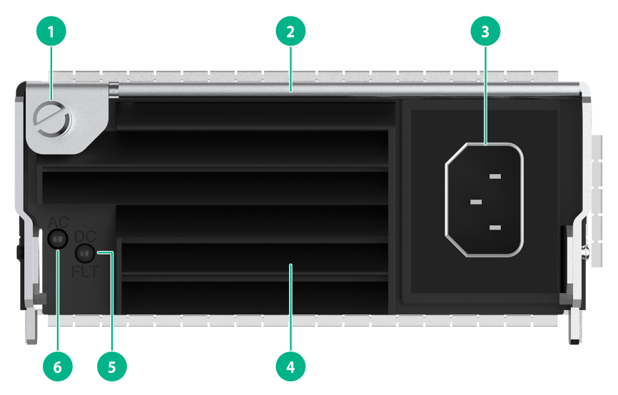
Figure2-18 PSR1200B-12A power supply view
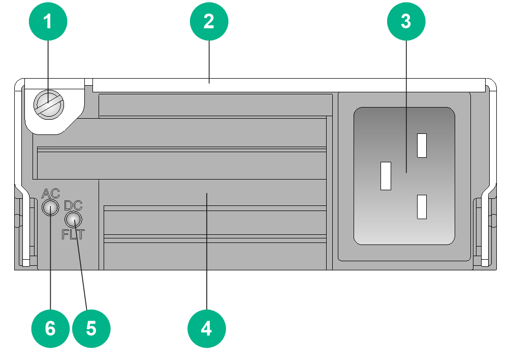
|
(1) Captive screw |
(2) Power supply handle |
|
(3) Power input receptacle |
(4) Air inlet vent |
|
(5) Power output status LED |
(6) Power input status LED |
LEDs
Table2-88 PSR1200B-12A LED description
|
LED mark |
Status |
Description |
|
AC |
Steady green |
The power supply system is operating correctly. |
|
Off |
No power input. |
|
|
The input voltage is too low and the power supply has entered self-protection state. |
||
|
DC |
Steady green |
Power output of the power supply system is normal. |
|
Steady red |
Power output of the power supply system is abnormal. The power supply has an output short circuit, output overcurrent, output overvoltage, input undervoltage, or remote shutdown alarm and has entered self-protection state. |
|
|
Steady amber |
An overtemperature alarm was triggered and the power supply has entered self-protection state. |
Technical specifications
Table2-89 Technical specifications
|
Item |
Description |
|
Dimensions (H × W × D) |
41 × 102 × 410 mm (1.61 × 4.02 × 16.14 in) |
|
Weight |
2.27 kg (5.00 lb) |
|
Inputs |
1 |
|
Rated input voltage range |
100 VAC to 240 VAC @ 50 Hz or 60 Hz |
|
Input voltage range |
90 VAC to 290 VAC |
|
Maximum input current |
16 A |
|
Rated output voltage |
12 VDC |
|
Rated output current |
100 A |
|
Rated output power |
1200 W |
|
Front-level circuit breaker/fuse |
≥ 20 A |
|
Heat dissipation |
Built-in fans |
|
Power cable |
Standard C19 cable (3*1.5mm²) |
PSR1200B-12A1-F
View
Figure2-19 PSR1200B-12A1-F power supply view
|
(1) Captive screw |
(2) Power supply handle |
|
(3) Power input receptacle |
(4) Air inlet vent |
|
(5) Power output status LED |
(6) Power input status LED |
LEDs
Table2-90 PSR1200B-12A1-F LED description
|
LED mark |
Status |
Description |
|
AC |
Steady green |
The power supply system is operating correctly. |
|
Off |
No power input. |
|
|
The input voltage is too low and the power supply has entered self-protection state. |
||
|
DC |
Steady green |
Power output of the power supply system is normal. |
|
Steady red |
Power output of the power supply system is abnormal. The power supply has an output short circuit, output overcurrent, output overvoltage, input undervoltage, or remote shutdown alarm and has entered self-protection state. |
|
|
Steady amber |
An overtemperature alarm was triggered and the power supply has entered self-protection state. |
Technical specifications
Table2-91 Technical specifications
|
Item |
Description |
|
Dimensions (H × W × D) |
41 × 102 × 410 mm (1.61 × 4.02 × 16.14 in) |
|
Weight |
2.27 kg (5.00 lb) |
|
Inputs |
1 |
|
Rated input voltage range |
200 VAC to 240 VAC @ 50 Hz or 60 Hz |
|
Input voltage range |
180 VAC to 264 VAC |
|
Maximum input current |
10 A |
|
Rated output voltage |
12 VDC |
|
Rated output current |
100 A |
|
Rated output power |
1200 W |
|
Front-level circuit breaker/fuse |
≥ 20 A |
|
Heat dissipation |
Built-in fans |
|
Power cable |
Standard C13 cable (3*1.0mm²) |
PSR2500-12A
View
Figure2-20 PSR2500-12A power supply view

|
(1) Captive screw |
(2) Power supply handle |
|
(3) Power input receptacle |
(4) Air inlet vent |
|
(5) Power output status LED |
(6) Power input status LED |
LEDs
Table2-92 PSR2500-12A LED description
|
LED mark |
Status |
Description |
|
AC |
Steady green |
The power supply system is operating correctly. |
|
Off |
No power input. |
|
|
The input voltage is too low and the power supply has entered self-protection state. |
||
|
DC |
Steady green |
Power output of the power supply system is normal. |
|
Steady red |
Power output of the power supply system is abnormal. The power supply has an output short circuit, output overcurrent, output overvoltage, input undervoltage, or remote shutdown alarm and has entered self-protection state. |
|
|
Steady amber |
An overtemperature alarm was triggered and the power supply has entered self-protection state. |
Technical specifications
Table2-93 Technical specifications
|
Item |
Description |
|
Dimensions (H × W × D) |
41 × 102 × 410 mm (1.61 × 4.02 × 16.14 in) |
|
Weight |
2.50 kg (5.51 lb) |
|
Inputs |
1 |
|
Rated input voltage range |
· 100 VAC to 240 VAC @ 50 Hz or 60 Hz · 240 VDC |
|
Input voltage range |
90 VAC to 264 VAC 190 VDC to 290 VDC |
|
Maximum input current |
16 A |
|
Rated output voltage |
12 VDC |
|
Rated output current |
· 100 A (100 VAC to 180 VAC input) · 208 A (180 VAC to 240 VAC or 240 VDC input) |
|
Rated output power |
· 1200 W (100 VAC to 180 VAC input) · 2500 W (180 VAC to 240 VAC or 240 VDC input) |
|
Front-level circuit breaker/fuse |
≥ 20 A |
|
Heat dissipation |
Built-in fans |
|
Power cable |
Standard C19 cable (3*1.5mm²) |
PSR2400-12D
View
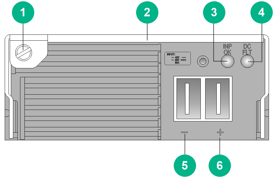
Figure2-21 PSR2400-12D power supply view
|
(1) Captive screw |
(2) Power supply handle |
|
(3) Power input status LED |
(4) Power output status LED |
|
(5) DC input negative terminal (–) |
(6) DC input positive terminal (+) |
LEDs
Table2-94 PSR2400-12D LED description
|
LED mark |
Status |
Description |
|
INP OK |
Steady green |
The power supply system is operating correctly. |
|
Off |
No power input. |
|
|
The input voltage is too low and the power supply has entered self-protection state. |
||
|
DC/FLT |
Steady green |
Power output of the power supply system is normal. |
|
Steady red |
Power output of the power supply system is abnormal. The power supply has an output short circuit, output overcurrent, output overvoltage, input undervoltage, or remote shutdown alarm and has entered self-protection state. |
|
|
Steady amber |
An overtemperature alarm was triggered and the power supply has entered self-protection state. |
Technical specifications
Table2-95 Technical specifications
|
Item |
Description |
|
Dimensions (H × W × D) |
41 × 102 × 410 mm (1.61 × 4.02 × 16.14 in) |
|
Weight |
2.40 kg (5.29 lb) |
|
Inputs |
1 |
|
Rated input voltage range |
–48 VDC to –60 VDC |
|
Input voltage range |
–36 V to –72 V |
|
Maximum input current |
78 A |
|
Rated output voltage |
12 VDC |
|
Rated output current |
200 A |
|
Rated output power |
2400 W |
|
Front-level circuit breaker/fuse |
≥ 100 A |
|
Heat dissipation |
Built-in fans |
|
Power cable |
PWC01 2P cable |
PSR2400-D
View
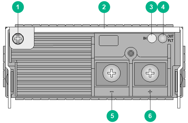
Figure2-22 PSR2400-D power supply view
|
(1) Captive screw |
(2) Power supply handle |
|
(3) Power input status LED |
(4) Power output status LED |
|
(5) DC input negative terminal (–) |
(6) DC input positive terminal (+) |
LEDs
Table2-96 PSR2400-D LED description
|
LED mark |
Status |
Description |
|
INP OK |
Steady green |
The power supply system is operating correctly. |
|
Off |
No power input. |
|
|
The input voltage is too low and the power supply has entered self-protection state. |
||
|
DC/FLT |
Steady green |
Power output of the power supply system is normal. |
|
Steady red |
Power output of the power supply system is abnormal. The power supply has an output short circuit, output overcurrent, output overvoltage, input undervoltage, or remote shutdown alarm and has entered self-protection state. |
|
|
Steady amber |
An overtemperature alarm was triggered and the power supply has entered self-protection state. |
Technical specifications
Table2-97 Technical specifications
|
Item |
Description |
|
Dimensions (H × W × D) |
41 × 102 × 410 mm (1.61 × 4.02 × 16.14 in) |
|
Weight |
2.40 kg (5.29 lb) |
|
Inputs |
1 |
|
Rated input voltage range |
–48 VDC to –60 VDC |
|
Input voltage range |
–36 V to –72 V |
|
Maximum input current |
78 A |
|
Rated output voltage |
12 VDC |
|
Rated output current |
200 A |
|
Rated output power |
2400 W |
|
Front-level circuit breaker/fuse |
≥ 100 A |
|
Heat dissipation |
Built-in fans |
|
Power cable |
ST M5 cable |
PSR2500B-12AHD-F
View
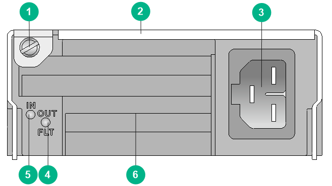
Figure2-23 PSR2500B-12AHD-F power supply view
|
(1) Captive screw |
(2) Power supply handle |
|
(3) Power input receptacle |
(4) Power output status LED |
|
(5) Power input status LED |
(6) Air inlet vent |
LEDs
Table2-98 PSR2500B-12AHD-F LED description
|
LED mark |
Status |
Description |
|
IN |
Steady green |
The power supply system is operating correctly. |
|
Off |
No power input. |
|
|
The input voltage is too low and the power supply has entered self-protection state. |
||
|
OUT |
Steady green |
Power output of the power supply system is normal. |
|
Steady red |
Power output of the power supply system is abnormal. The power supply has an output short circuit, output overcurrent, output overvoltage, input undervoltage, or remote shutdown alarm and has entered self-protection state. |
|
|
Steady amber |
An overtemperature alarm was triggered and the power supply has entered self-protection state. |
Technical specifications
Table2-99 Technical specifications
|
Item |
Description |
|
Dimensions (H × W × D) |
41 × 102 × 410 mm (1.61 × 4.02 × 16.14 in) |
|
Weight |
2.75 kg (6.06 lb) |
|
Inputs |
1 |
|
Rated input voltage range |
· 100 VAC to 240 VAC @ 50 Hz or 60 Hz · 240 VDC to 380 VDC |
|
Input voltage range |
90 VAC to 290 VAC 180 VDC to 400 VDC |
|
Maximum input current |
16 A |
|
Rated output voltage |
12 VDC |
|
Rated output current |
· 100 A (90 VAC to 180 VAC input) · 208 A (180 VAC to 290 VAC or 180 VDC to 400 VDC input) |
|
Rated output power |
· 1200 W (90 VAC to 180 VAC input) · 2500 W (180 VAC to 290 VAC or 180 VDC to 400 VDC input) |
|
Front-level circuit breaker/fuse |
≥ 20A |
|
Heat dissipation |
Built-in fans |
|
Power cable |
Standard HVDCB cable (3*1.5mm²) |
Fan trays
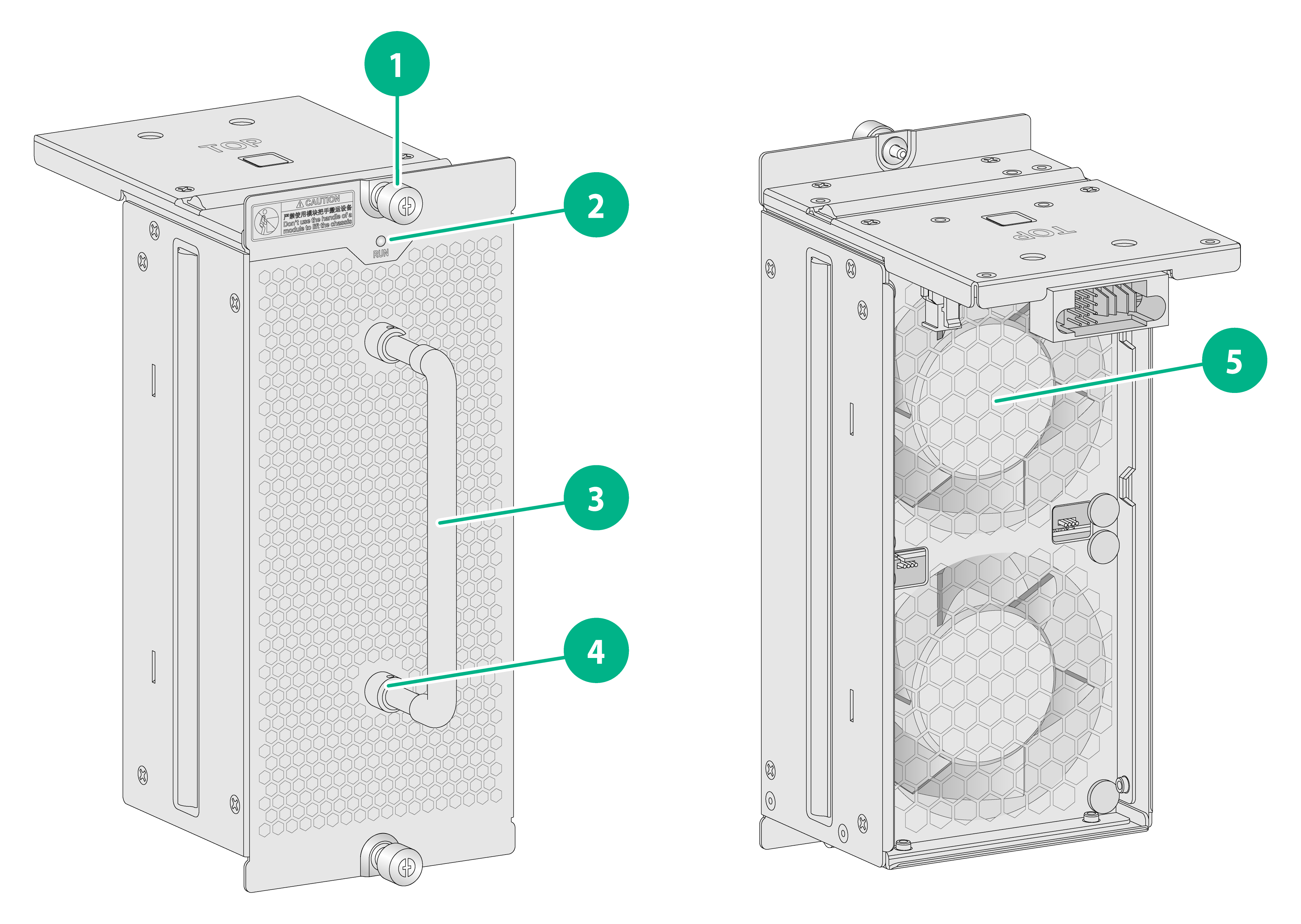
FAN-80B-2-A
View
Figure2-24 FAN-80B-2-A fan tray view
|
(1) Captive screw |
(2) Status LED |
|
(3) Fan tray handle |
(4) Fan tray handle pivot |
|
(5) Fan |
|
LEDs
Table2-100 Fan tray LED description
|
LED mark |
Status |
Description |
|
RUN |
Steady green |
The fan tray is operating correctly. |
|
Steady red |
The following are the possible causes: · One or more fans in the fan tray have failed. · The fan tray is not installed securely. |
|
|
Off |
The fan tray is not powered on. |
Technical specifications
Table2-101 Technical specifications
|
Item |
Description |
|
Dimensions (H × W × D) |
200 × 86 × 120 mm (7.87 × 3.39 × 4.72 in) |
|
Weight |
0.95 kg (2.09 lb) |
|
Maximum power consumption |
95 W |
|
Power consumption (with typical configuration) |
36 W |
|
Minimum power consumption |
9 W |
|
Number of fans |
2 |
|
Fan diameter |
80 mm (3.15 in) |
|
Max fan speed |
15200 RPM |
|
Maximum air flow rate |
260 CFM (7.36 m3/min) |
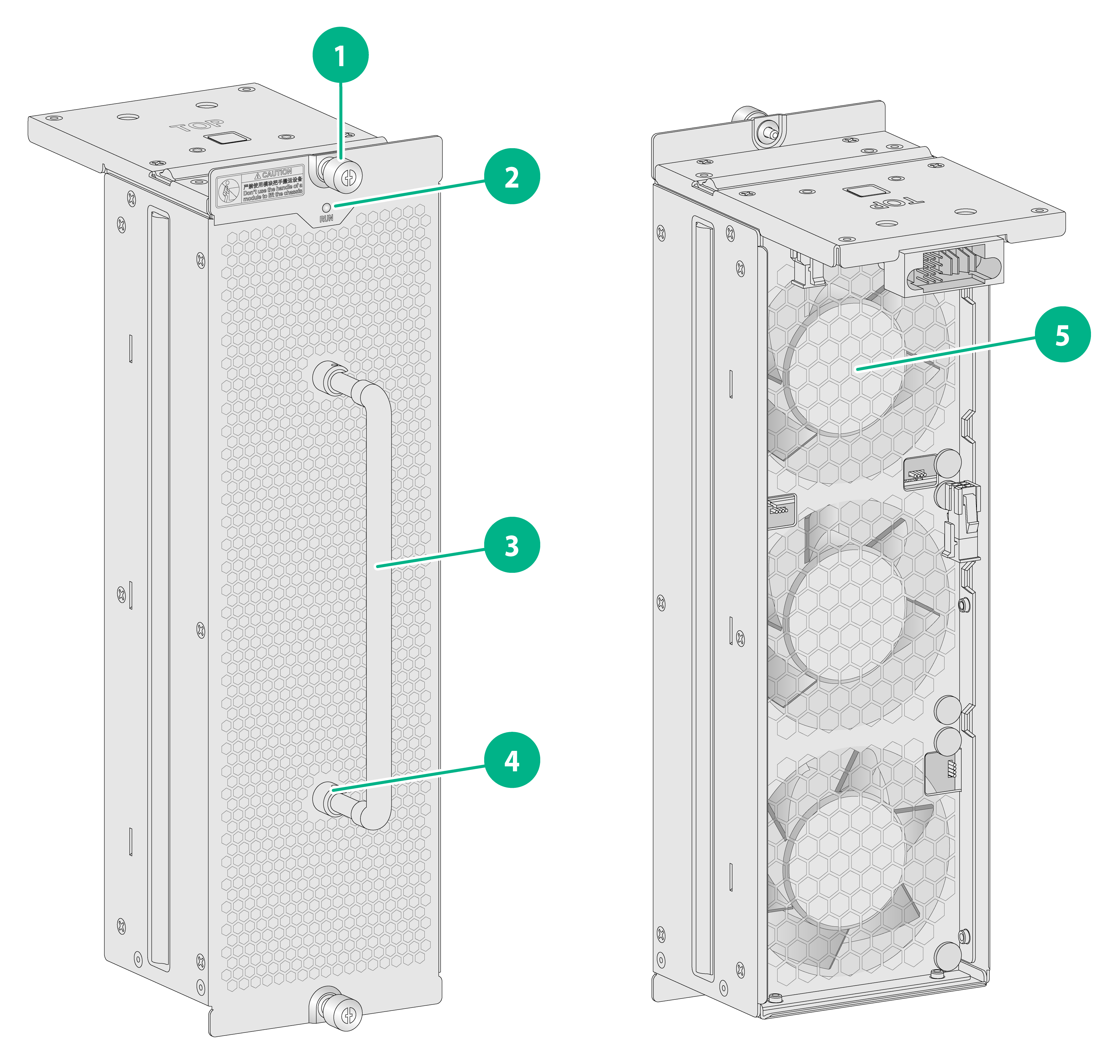
FAN-80B-3-A
View
Figure2-25 FAN-80B-3-A fan tray view
|
(1) Captive screw |
(2) Status LED |
|
(3) Fan tray handle |
(4) Fan tray handle pivot |
|
(5) Fan |
|
LEDs
Table2-102 Fan tray LED description
|
LED mark |
LED |
Description |
|
RUN |
Steady green |
The fan tray is operating correctly. |
|
Steady red |
The following are the possible causes: · One or more fans in the fan tray have failed. · The fan tray is not installed securely. |
|
|
Off |
The fan tray is not powered on. |
Technical specifications
Table2-103 Technical specifications
|
Item |
Description |
|
Dimensions (H × W × D) |
289 × 86 × 120 mm (11.38 × 3.39 × 4.72 in) |
|
Weight |
1.30 kg (2.87 lb) |
|
Maximum power consumption |
140 W |
|
Power consumption (with typical configuration) |
45 W |
|
Minimum power consumption |
12 W |
|
Number of fans |
3 |
|
Fan diameter |
80 mm (3.15 in) |
|
Max fan speed |
15200 RPM |
|
Maximum air flow rate |
390 CFM (11.04 m3/min) |
Configuration restrictions and guidelines
The router came with two fan trays installed. To replace a fan tray, make sure the new fan tray is compatible with the router.
Compatibility information
Table2-104 Compatibility matrix between fan trays and routers
|
Fan tray |
Compatible router model |
|
FAN-80B-2-A |
CR16000-M8 |
|
FAN-80B-3-A |
CR16000-M16 |
Slide rails
Before rack-mounting the router, install slide rails on the rack.
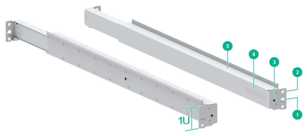
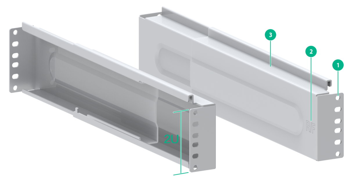
LSXM1BSR
Views
Figure2-26 LSXM1BSR slide rail view
|
(1) Positioning tongue |
(2) Slide rail installation hole |
|
(3) Front plate installation hole |
(4) Sign |
|
(5) Guide rail |
|
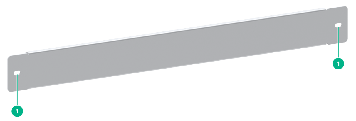
Figure2-27 Front plate
|
(1) Installation hole |
Technical specifications
Table2-105 Technical specifications
|
Item |
Description |
|
Maximum loading capacity |
650 kg (1432.98 lb) |
|
Adjustment range |
630 to 900 mm (24.80 to 35.43 in) |
|
Occupied rack space |
1 RU |
LSTM1KSGD0
Views
Figure2-28 LSTM1KSGD0 slide rail view
|
(1) Installation hole |
(2) Sign |
|
(3) Guide rail |
|
Technical specifications
Table2-106 Technical specifications
|
Item |
Description |
|
Maximum loading capacity |
280 kg (617.28 lb) |
|
Adjustment range |
300 to 500 mm (11.81 to 19.69 in) |
|
Occupied rack space |
2 RUs |
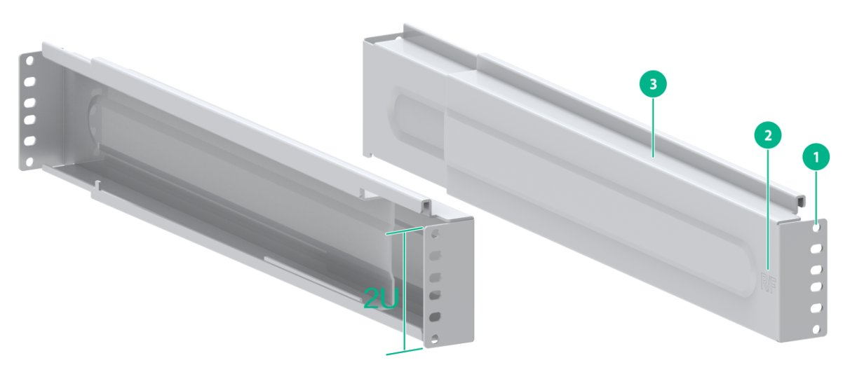
LSTM2KSGD0
Views
Figure2-29 LSTM2KSGD0 slide rail view
|
(1) Installation hole |
(2) Sign |
|
(3) Guide rail |
|
Technical specifications
Table2-107 Technical specifications
|
Item |
Description |
|
Maximum loading capacity |
400 kg (881.83 lb) |
|
Adjustment range |
500 to 800 mm (19.69 to 31.50 in) |
|
Occupied rack space |
2 RUs |
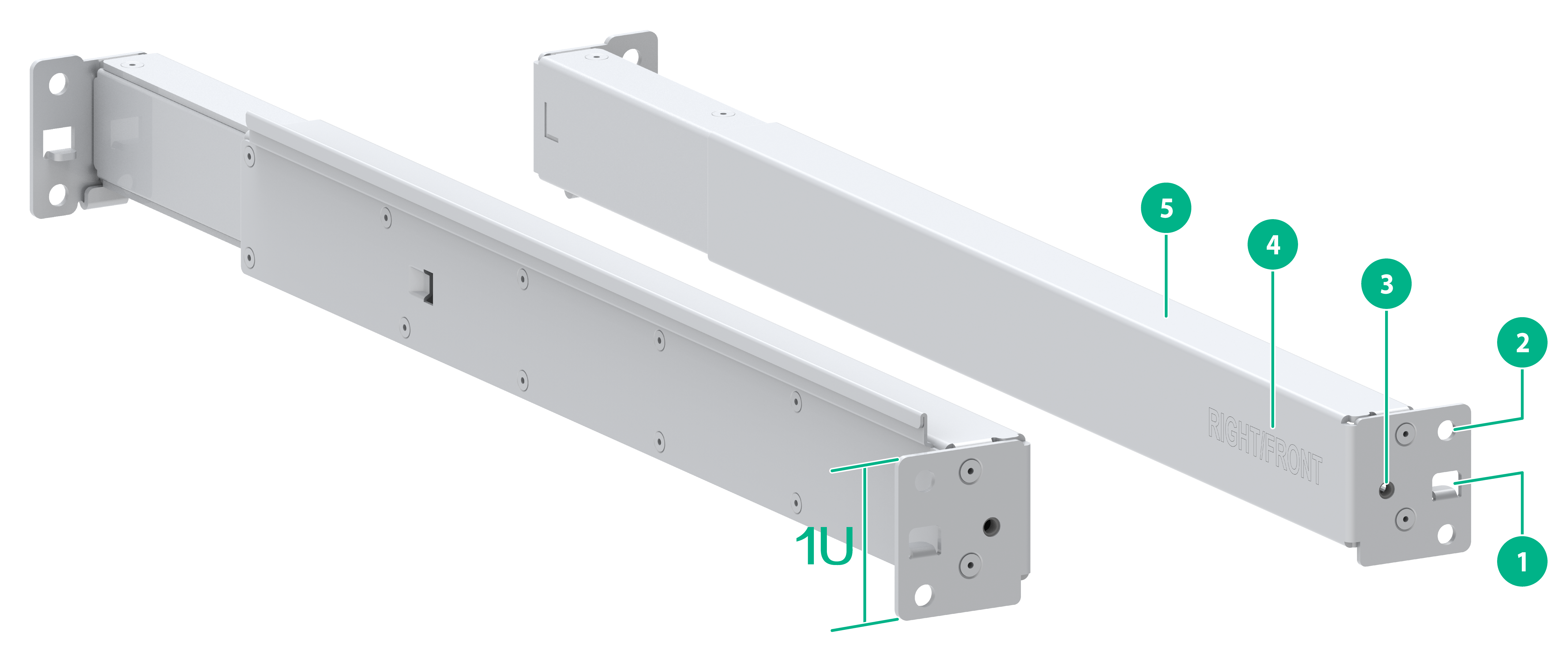
RL-1U-A
Views
Figure2-30 RL-1U-A slide rail view
|
(1) Positioning tongue |
(2) Slide rail installation hole |
|
(3) Front plate installation hole |
(4) Sign |
|
(5) Guide rail |
|
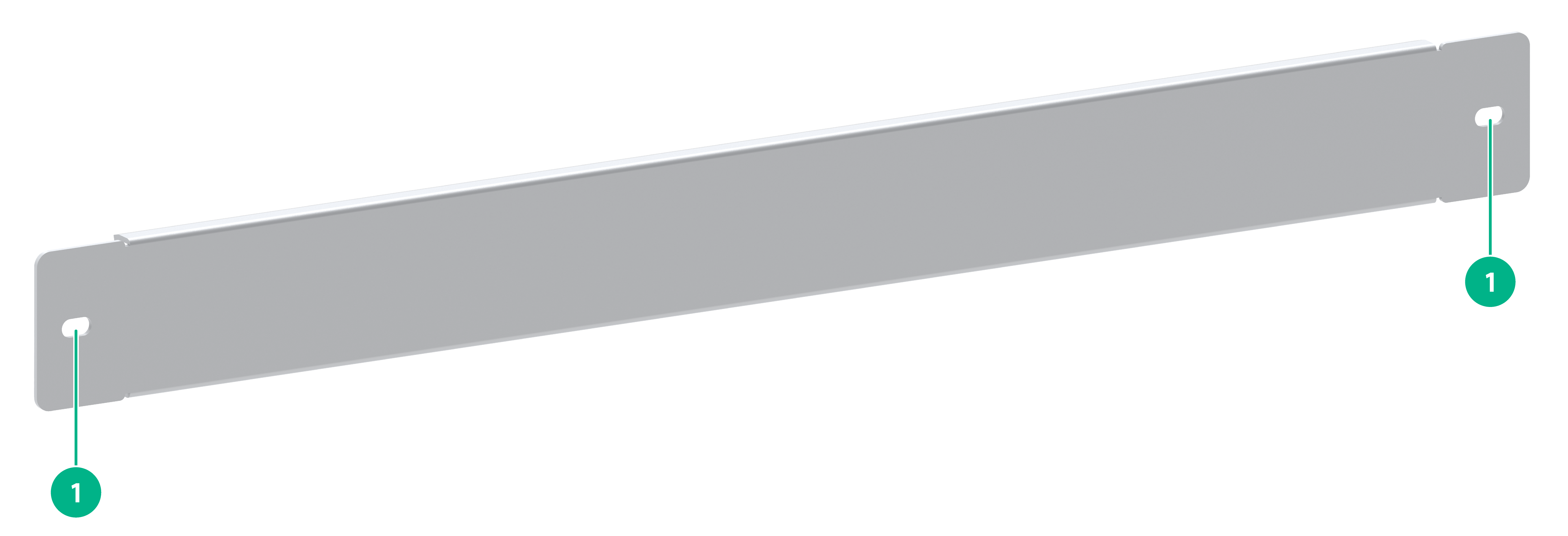
Figure2-31 Front plate
|
(1) Installation hole |
Technical specifications
Table2-108 Technical specifications
|
Item |
Description |
|
Maximum loading capacity |
200 kg (440.92 lb) |
|
Adjustment range |
380 to 630 mm (14.96 to 24.80 in) |
|
Occupied rack space |
1 RU |
Configuration restrictions and guidelines
Select slide rails for the router based on the chassis weight.
Compatibility information
Table2-109 Chassis weights and applicable slide rails
|
Model |
Chassis weight (fully configured) |
Applicable slide rails |
|
CR16000-M8 |
66 kg (145.50 lb) |
LSXM1BSR LSTM1KSGD0 LSTM2KSGD0 RL-1U-A |
|
CR16000-M16 |
81 kg (178.57 lb) |
LSXM1BSR LSTM1KSGD0 LSTM2KSGD0 RL-1U-A |
DC power cords
DC power cords are used for connecting the DC power supplies of a CR16000-M router to the external DC power supply system. For more information, see DC power cord in "Cables."
AC power cords
AC power cords are used for connecting the AC power supplies of a CR16000-M router to the external AC power supply system. For more information, see AC power cord in "Cables."
