- Table of Contents
-
- 05-Network Connectivity Configuration Guide
- 00-Preface
- 01-About the network connectivity configuration guide
- 02-MAC address table configuration
- 03-Ethernet link aggregation configuration
- 04-Port isolation configuration
- 05-VLAN configuration
- 06-Loop detection configuration
- 07-Spanning tree configuration
- 08-LLDP configuration
- 09-Layer 2 forwarding configuration
- 10-L2TP configuration
- 11-ARP configuration
- 12-IP addressing configuration
- 13-DHCP configuration
- 14-DHCP snooping configuration
- 15-DHCPv6 configuration
- 16-DHCPv6 snooping configuration
- 17-DNS configuration
- 18-HTTP configuration
- 19-IP forwarding basics configuration
- 20-Fast forwarding configuration
- 21-Adjacency table configuration
- 22-IP performance optimization configuration
- 23-IPv6 basics configuration
- 24-IPv6 neighbor discovery configuration
- 25-IPv6 fast forwarding configuration
- 26-NAT configuration
- 27-Basic IP routing configuration
- 28-Static routing configuration
- 29-OSPF configuration
- 30-Policy-based routing configuration
- 31-IPv6 static routing configuration
- 32-IPv6 policy-based routing configuration
- 33-GRE configuration
- 34-IPv6 transition technologies configuration
- 35-Multicast overview
- 36-IGMP snooping configuration
- 37-MLD snooping configuration
- Related Documents
-
| Title | Size | Download |
|---|---|---|
| 34-IPv6 transition technologies configuration | 136.76 KB |
IPv6 transition technologies overview
About IPv6 transition technologies
Configuring IPv6 over IPv4 tunneling
Configuring an IPv6 over IPv4 manual tunnel
Example: Configuring an IPv6 over IPv4 manual tunnel
Example: Configuring an ISATAP tunnel
Verifying and maintaining IPv6 over IPv4 tunneling
Displaying IPv6 over IPv4 tunnel interface information
Clearing IPv6 over IPv4 tunnel interface information
IPv6 transition technologies overview
About IPv6 transition technologies
IPv6 transition technologies enable communication between IPv4 and IPv6 networks.
Tunneling
Tunneling uses one network protocol to encapsulate the packets of another network protocol and transfers them over the network. For example, IPv6 over IPv4 tunneling.
IPv6 over IPv4 tunneling
Implementation
IPv6 over IPv4 tunneling enables isolated IPv6 networks to communicate, as shown in Figure 1.
|
|
NOTE: The devices at both ends of an IPv6 over IPv4 tunnel must support the IPv4/IPv6 dual stack. |
Figure 1 IPv6 over IPv4 tunnel
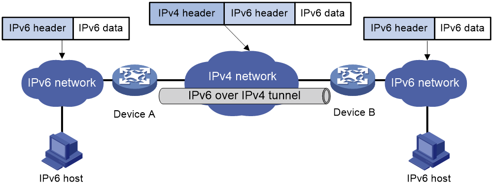
The IPv6 over IPv4 tunnel processes packets by using the following steps:
1. A host in the IPv6 network sends an IPv6 packet to Device A at the tunnel source.
2. After Device A receives the IPv6 packet, it processes the packet as follows:
a. Searches the routing table to identify the outgoing interface for the IPv6 packet.
The outgoing interface is the tunnel interface, so Device A knows that the packet needs to be forwarded through the tunnel.
b. Adds an IPv4 header to the IPv6 packet and forwards the packet through the physical interface of the tunnel.
In the IPv4 header, the source IPv4 address is the IPv4 address of the tunnel source, and the destination IPv4 address is the IPv4 address of the tunnel destination.
3. Upon receiving the packet, Device B de-encapsulates the packet.
4. If the destination address of the IPv6 packet is itself, Device B forwards it to the upper-layer protocol. If it is not, Device B forwards it according to the routing table.
Configuring IPv6 over IPv4 tunneling
Configuring an IPv6 over IPv4 manual tunnel
Restrictions and guidelines
When you perform tasks in this section, follow these restrictions and guidelines:
· The tunnel destination address specified on the local device must be identical with the tunnel source address specified on the tunnel peer device.
· Do not specify the same tunnel source and destination addresses for the tunnel interfaces in the same mode on a device.
· To ensure correct packet forwarding, identify whether the destination IPv6 network and the IPv6 address of the local tunnel interface are on the same subnet. If they are not, configure a route reaching the destination IPv6 network through the tunnel interface. You can configure the route by using one of the following methods:
¡ Configure a static route, and specify the local tunnel interface as the outgoing interface or specify the IPv6 address of the peer tunnel interface as the next hop.
¡ Enable a dynamic routing protocol on both the local and remote tunnel interfaces.
For more information about route configuration, see Network Connectivity Configuration Guide.
· IPv6 over IPv4 manual tunnel configuration commands include the following common tunnel interface commands:
¡ interface tunnel.
¡ source.
¡ destination.
¡ tunnel dfbit enable.
For more information about these and more tunnel interface commands, see Interface Command Reference.
Procedure
1. Enter system view.
system-view
2. Enter IPv6 over IPv4 manual tunnel interface view.
interface tunnel number [ mode ipv6-ipv4 ]
3. Specify an IPv6 address for the tunnel interface.
See basic IPv6 settings in Network Connectivity Configuration Guide.
4. Configure a source address or source interface for the tunnel interface.
source { ipv4-address | interface-type interface-number }
By default, no source address or source interface is configured for the tunnel interface.
If you specify a source address, it is used as the source IP address of tunneled packets.
If you specify a source interface, the primary IP address of this interface is used as the source IP address of tunneled packets.
5. Configure a destination address for the tunnel interface.
destination ipv4-address
By default, no destination address is configured for the tunnel interface.
The tunnel destination address must be the IP address of the receiving interface on the tunnel peer. It is used as the destination IP address of tunneled packets.
6. (Optional.) Set the DF bit for tunneled packets.
tunnel dfbit enable
By default, the DF bit is not set for tunneled packets.
Example: Configuring an IPv6 over IPv4 manual tunnel
Network configuration
As shown in Figure 2, configure an IPv6 over IPv4 tunnel between Device A and Device B so the two IPv6 networks can reach each other over the IPv4 network. Because the tunnel destination IPv4 address cannot be automatically obtained from the destination IPv6 addresses, configure an IPv6 over IPv4 manual tunnel.
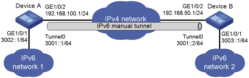
Prerequisites
Make sure Device A and Device B can reach each other through IPv4.
Procedure
1. Configure Device A:
# Assign an IPv4 address to interface GigabitEthernet 1/0/2.
<DeviceA> system-view
[DeviceA] interface gigabitethernet 1/0/2
[DeviceA-GigabitEthernet1/0/2] ip address 192.168.100.1 255.255.255.0
[DeviceA-GigabitEthernet1/0/2] quit
# Assign an IPv6 address to interface GigabitEthernet 1/0/1.
[DeviceA] interface gigabitethernet 1/0/1
[DeviceA-GigabitEthernet1/0/1] ipv6 address 3002::1 64
[DeviceA-GigabitEthernet1/0/1] quit
# Create IPv6 over IPv4 manual tunnel interface Tunnel 0.
[DeviceA] interface tunnel 0 mode ipv6-ipv4
# Specify an IPv6 address for the tunnel interface.
[DeviceA-Tunnel0] ipv6 address 3001::1/64
# Specify GigabitEthernet 1/0/2 as the source interface of the tunnel.
[DeviceA-Tunnel0] source gigabitethernet 1/0/2
# Specify the IP address of GigabitEthernet 1/0/2 on Device B as the destination address of the tunnel.
[DeviceA-Tunnel0] destination 192.168.50.1
[DeviceA-Tunnel0] quit
# Configure a static route destined for IPv6 network 2 through Tunnel 0.
[DeviceA] ipv6 route-static 3003:: 64 tunnel 0
2. Configure Device B:
# Assign an IPv4 address to interface GigabitEthernet 1/0/2.
<DeviceB> system-view
[DeviceB] interface gigabitethernet 1/0/2
[DeviceB-GigabitEthernet1/0/2] ip address 192.168.50.1 255.255.255.0
[DeviceB-GigabitEthernet1/0/2] quit
# Assign an IPv6 address to interface GigabitEthernet 1/0/1.
[DeviceB] interface gigabitethernet 1/0/1
[DeviceB-GigabitEthernet1/0/1] ipv6 address 3003::1 64
[DeviceB-GigabitEthernet1/0/1] quit
# Create IPv6 over IPv4 manual tunnel interface Tunnel 0.
[DeviceB] interface tunnel 0 mode ipv6-ipv4
# Specify an IPv6 address for the tunnel interface.
[DeviceB-Tunnel0] ipv6 address 3001::2/64
# Specify GigabitEthernet 1/0/2 as the source interface of the tunnel.
[DeviceB-Tunnel0] source gigabitethernet 1/0/2
# Specify the IP address of GigabitEthernet 1/0/2 on Device A as the destination address of the tunnel.
[DeviceB-Tunnel0] destination 192.168.100.1
[DeviceB-Tunnel0] quit
# Configure a static route destined for IPv6 network 1 through Tunnel 0.
[DeviceB] ipv6 route-static 3002:: 64 tunnel 0
Verifying the configuration
# Use the display ipv6 interface command to display tunnel interface status on Device A and Device B. Verify that interface Tunnel 0 is up. (Details not shown.)
# Verify that Device A and Device B can ping the IPv6 address of GigabitEthernet 1/0/1 of each other. This example uses Device A.
[DeviceA] ping ipv6 3003::1
Ping6(56 data bytes) 3001::1 --> 3003::1, press CTRL_C to break
56 bytes from 3003::1, icmp_seq=0 hlim=64 time=45.000 ms
56 bytes from 3003::1, icmp_seq=1 hlim=64 time=10.000 ms
56 bytes from 3003::1, icmp_seq=2 hlim=64 time=4.000 ms
56 bytes from 3003::1, icmp_seq=3 hlim=64 time=10.000 ms
56 bytes from 3003::1, icmp_seq=4 hlim=64 time=11.000 ms
--- Ping6 statistics for 3003::1 ---
5 packet(s) transmitted, 5 packet(s) received, 0.0% packet loss
round-trip min/avg/max/std-dev = 4.000/16.000/45.000/14.711 ms
Configuring an ISATAP tunnel
Restrictions and guidelines
Follow these guidelines when you configure an ISATAP tunnel:
· You do not need to configure a destination address for an ISATAP tunnel, because the destination IPv4 address is embedded in the ISATAP address.
· Do not specify the same source addresses for local tunnel interfaces in the same tunnel mode.
· Because automatic tunnels do not support dynamic routing, configure a static route destined for the destination IPv6 network at each tunnel end. You can specify the local tunnel interface as the egress interface of the route or specify the IPv6 address of the peer tunnel interface as the next hop of the route. For more information about route configuration, see "Configuring IPv6 static routing."
· ISATAP tunnel configuration commands include the following common tunnel interface commands:
¡ interface tunnel.
¡ source.
¡ tunnel dfbit enable.
For more information about these and more tunnel interface commands, see Interface Command Reference.
Procedure
1. Enter system view.
system-view
2. Enter ISATAP tunnel interface view.
interface tunnel number [ mode ipv6-ipv4 isatap ]
3. Specify an IPv6 address for the tunnel interface.
See "Configuring basic IPv6 settings."
4. Configure a source address or source interface for the tunnel interface.
source { ipv4-address | interface-type interface-number }
By default, no source address or source interface is configured for the tunnel interface.
If you specify a source address, it is used as the source IP address of tunneled packets.
If you specify a source interface, the primary IP address of this interface is used as the source IP address of tunneled packets.
5. (Optional.) Set the DF bit for tunneled packets.
tunnel dfbit enable
By default, the DF bit is not set for tunneled packets.
Example: Configuring an ISATAP tunnel
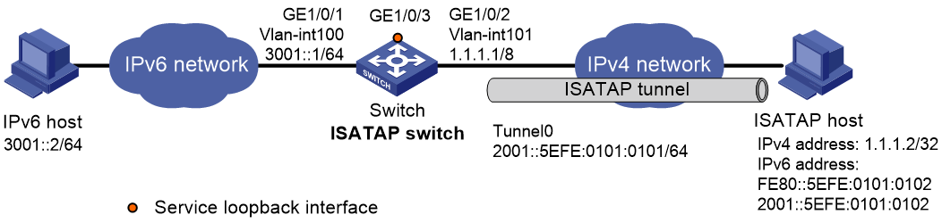
Network configuration
As shown in Figure 3, configure an ISATAP tunnel between the switch and the ISATAP host so the ISATAP host in the IPv4 network can access the IPv6 network.
Procedure
1. Configure the switch:
# Add GigabitEthernet 1/0/1 to VLAN 100.
<Switch> system-view
[Switch] vlan 100
[Switch-vlan100] port gigabitethernet 1/0/1
[Switch-vlan100] quit
# Specify an IPv6 address for VLAN-interface 100.
[Switch] interface vlan-interface 100
[Switch-Vlan-interface100] ipv6 address 3001::1/64
[Switch-Vlan-interface100] quit
# Add GigabitEthernet 1/0/2 (the physical interface of the tunnel) to VLAN 101.
[Switch] vlan 101
[Switch-vlan101] port gigabitethernet 1/0/2
[Switch-vlan101] quit
# Specify an IPv4 address for VLAN-interface 101.
[Switch] interface vlan-interface 101
[Switch-Vlan-interface101] ip address 1.1.1.1 255.0.0.0
[Switch-Vlan-interface101] quit
# Create service loopback group 1, and specify its service type as tunnel.
[Switch] service-loopback group 1 type tunnel
# Assign GigabitEthernet 1/0/3 to service loopback group 1.
[Switch] interface gigabitethernet 1/0/3
[Switch-GigabitEthernet1/0/3] port service-loopback group 1
[Switch-GigabitEthernet1/0/3] quit
# Create ISATAP tunnel interface Tunnel 0.
[Switch] interface tunnel 0 mode ipv6-ipv4 isatap
# Specify an EUI-64 IPv6 address for the tunnel interface.
[Switch-Tunnel0] ipv6 address 2001:: 64 eui-64
# Specify VLAN-interface 101 as the source interface of the tunnel interface.
[Switch-Tunnel0] source vlan-interface 101
# Disable RA suppression so that the ISATAP host can acquire information such as the address prefix from the RA message advertised by the ISATAP switch.
[Switch-Tunnel0] undo ipv6 nd ra halt
[Switch-Tunnel0] quit
2. Configure the ISATAP host:
Configurations on the ISATAP host vary by operating system. The following configuration is performed on Windows XP.
# Install IPv6.
C:\>ipv6 install
# On a host running Windows XP, the ISATAP interface is typically interface 2. Display information about the ISATAP interface.
C:\>ipv6 if 2
Interface 2: Automatic Tunneling Pseudo-Interface
Guid {48FCE3FC-EC30-E50E-F1A7-71172AEEE3AE}
does not use Neighbor Discovery
does not use Router Discovery
routing preference 1
EUI-64 embedded IPv4 address: 0.0.0.0
router link-layer address: 0.0.0.0
preferred link-local fe80::5efe:1.1.1.2, life infinite
link MTU 1280 (true link MTU 65515)
current hop limit 128
reachable time 42500ms (base 30000ms)
retransmission interval 1000ms
DAD transmits 0
default site prefix length 48
# Specify an IPv4 address for the ISATAP switch.
C:\>netsh interface ipv6 isatap set router 1.1.1.1
# Display information about the ISATAP interface.
C:\>ipv6 if 2
Interface 2: Automatic Tunneling Pseudo-Interface
Guid {48FCE3FC-EC30-E50E-F1A7-71172AEEE3AE}
does not use Neighbor Discovery
uses Router Discovery
routing preference 1
EUI-64 embedded IPv4 address: 1.1.1.2
router link-layer address: 1.1.1.1
preferred global 2001::5efe:1.1.1.2, life 29d23h59m46s/6d23h59m46s (public)
preferred link-local fe80::5efe:1.1.1.2, life infinite
link MTU 1500 (true link MTU 65515)
current hop limit 255
reachable time 42500ms (base 30000ms)
retransmission interval 1000ms
DAD transmits 0
default site prefix length 48
The host has obtained the address prefix 2001::/64 and has automatically generated the global unicast address 2001::5efe:1.1.1.2. The message "uses Router Discovery" indicates that the router discovery feature is enabled on the host.
# Display information about IPv6 routes on the host.
C:\>ipv6 rt
2001::/64 -> 2 pref 1if+8=9 life 29d23h59m43s (autoconf)
::/0 -> 2/fe80::5efe:1.1.1.1 pref 1if+256=257 life 29m43s (autoconf)
3. On the IPv6 host, configure a route to the ISATAP switch.
C:\>netsh interface ipv6 set route 2001::/64 5 3001::1
Verifying the configuration
# Verify that the ISATAP host can ping the IPv6 host.
C:\>ping 3001::2
Pinging 3001::2 with 32 bytes of data:
Reply from 3001::2: time=1ms
Reply from 3001::2: time=1ms
Reply from 3001::2: time=1ms
Reply from 3001::2: time=1ms
Ping statistics for 3001::2:
Packets: Sent = 4, Received = 4, Lost = 0 (0% loss),
Approximate round trip times in milli-seconds:
Minimum = 1ms, Maximum = 1ms, Average = 1ms
Verifying and maintaining IPv6 over IPv4 tunneling
Displaying IPv6 over IPv4 tunnel interface information
Perform display tasks in any view.
· Display IPv6 over IPv4 tunnel interface information.
display tunnel-interface [ number ]
For more information about this command, see tunnel interface commands in Interface Command Reference.
· Display information about IPv6 over IPv4 tunnel interfaces.
display interface [ tunnel [ number ] ] [ brief [ description | down ] ]
For more information about this command, see tunnel interface commands in Interface Command Reference.
· Display IPv6 information about IPv6 over IPv4 tunnel interfaces.
display ipv6 interface [ tunnel [ number ] ] [ brief ]
For more information about this command, see IPv6 basics in Network Connectivity Command Reference.
Clearing IPv6 over IPv4 tunnel interface information
Perform clear tasks in user view.
· Clear IPv6 over IPv4 tunnel interface statistics.
reset counters interface [ tunnel [ number ] ]
For more information about this command, see common interface commands in Interface Command Reference.
· Clear IPv6 statistics on IPv6 over IPv4 tunnel interfaces.
reset ipv6 statistics
For more information about this command, see IPv6 basics in Layer 3—IP Services Command Reference.
