- Table of Contents
-
- 06-IP Multicast Configuration Guide
- 01-Multicast overview
- 02-IGMP snooping configuration
- 03-PIM snooping configuration
- 04-Multicast VLAN configuration
- 05-Multicast routing and forwarding configuration
- 06-IGMP configuration
- 07-PIM configuration
- 08-MSDP configuration
- 09-MLD snooping configuration
- 10-IPv6 PIM snooping configuration
- 11-IPv6 multicast VLAN configuration
- 12-IPv6 multicast routing and forwarding configuration
- 13-MLD configuration
- 14-IPv6 PIM configuration
- Related Documents
-
| Title | Size | Download |
|---|---|---|
| 12-IPv6 multicast routing and forwarding configuration | 212.96 KB |
Contents
Configuring IPv6 multicast routing and forwarding
About IPv6 multicast routing and forwarding
IPv6 multicast forwarding across IPv6 unicast subnets
IPv6 multicast routing and forwarding tasks at a glance
Prerequisites for IPv6 multicast routing and forwarding
Enabling IPv6 multicast routing
Configuring static IPv6 multicast routes
Specifying the longest prefix match principle
Configuring IPv6 multicast load splitting
Configuring an IPv6 multicast forwarding boundary
Using mtrace2 to trace an IPv6 multicast path
Setting the maximum number of cached unknown IPv6 multicast packets
Display and maintenance commands for IPv6 multicast routing and forwarding
IPv6 multicast routing and forwarding configuration examples
Example: Configuring IPv6 multicast forwarding over a GRE tunnel
Example: Changing an RPF route
Example: Creating an RPF route
Configuring IPv6 multicast routing and forwarding
About IPv6 multicast routing and forwarding
Each IPv6 multicast routing protocol has its own routing table. Multicast routing information in routing entries generated by the IPv6 multicast routing protocols are summarized in a set of (S, G) and (*, G) entries. All the (S, G) and (*, G) entries form a general IPv6 multicast routing table. The optimal IPv6 multicast routing entries in the general IPv6 multicast routing table are added to the IPv6 multicast forwarding table to guide IPv6 multicast data forwarding.
RPF check mechanism
An IPv6 multicast routing protocol uses the reverse path forwarding (RPF) check mechanism to ensure IPv6 multicast data delivery along the correct path and to avoid data loops.
RPF check process
An IPv6 multicast device performs the RPF check on an IPv6 multicast packet as follows:
1. Chooses an optimal route back to the packet source separately from the IPv6 unicast and IPv6 MBGP routing tables. The IPv6 MBGP routing table is not supported in the current software version.
In RPF check, the "packet source" means difference things in difference situations:
¡ For a packet that travels along the SPT, the packet source is the IPv6 multicast source.
¡ For a packet that travels along the RPT, the packet source is the RP.
¡ For a bootstrap message originated from the BSR, the packet source is the BSR.
For more information about the concepts of SPT, RPT, source-side RPT, RP, and BSR, see "IPv6 PIM overview."
2. Selects one of the optimal routes as the RPF route as follows:
¡ If the device uses the longest prefix match principle, the route with a higher prefix length becomes the RPF route. If the routes have the same prefix length, the route with a higher route preference becomes the RPF route. If the routes have the same route preference, the IPv6 MBGP route becomes the RPF route. If equal cost routes exist, the equal cost route with the highest next hop IPv6 address becomes the RPF route.
For more information about the route preference, see Layer 3—IP Routing Configuration Guide.
¡ If the device does not use the longest prefix match principle, the route with a higher route preference becomes the RPF route. If the routes have the same route preference, the IPv6 MBGP route becomes the RPF route. If equal cost routes exist, the equal cost route with the highest next hop IPv6 address becomes the RPF route.
In the RPF route, the outgoing interface is the RPF interface and the next hop is the RPF neighbor.
3. Determines whether the packet arrived at the RPF interface.
¡ If the packet arrived at the RPF interface, the RPF check succeeds and the packet is forwarded.
¡ If the packet arrived at the non-RPF interface, the RPF check fails and the packet is discarded.
RPF check implementation in IPv6 multicast
Implementing an RPF check on each received IPv6 multicast packet would heavily burden the device. The use of an IPv6 multicast forwarding table is the solution to this issue. When the device creates an IPv6 multicast forwarding entry for an IPv6 (S, G) packet, it sets the RPF interface of the packet as the incoming interface of the (S, G) entry. After the device receives another (S, G) packet, it looks up its IPv6 multicast forwarding table for a matching (S, G) entry.
· If no match is found, the device first determines the RPF route back to the packet source. Then, it creates a forwarding entry with the RPF interface as the incoming interface and performs one of the following tasks:
¡ If the receiving interface is the RPF interface, the RPF check succeeds and the device forwards the packet out of all outgoing interfaces.
¡ If the receiving interface is not the RPF interface, the RPF check fails and the device discards the packet.
· If a match is found and the matching forwarding entry contains the receiving interface, the device forwards the packet out of all outgoing interfaces.
· If a match is found but the matching forwarding entry does not contain the receiving interface, the device determines the RPF route back to the packet source. Then, the device performs one of the following tasks:
¡ If the RPF interface is the incoming interface, it means that the forwarding entry is correct but the packet traveled along a wrong path. The packet fails the RPF check, and the device discards the packet.
¡ If the RPF interface is not the incoming interface, it means that the forwarding entry has expired. The device replaces the incoming interface with the RPF interface and matches the receiving interface against the RPF interface. If the receiving interface is the RPF interface, the device forwards the packet out of all outgoing interfaces. Otherwise, it discards the packet.
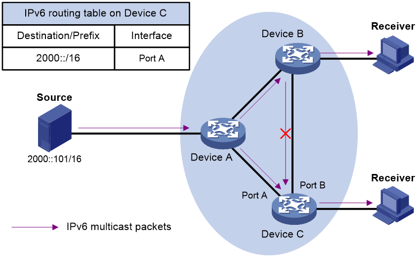
As shown in Figure 1, assume that IPv6 unicast routes are available on the network. IPv6 MBGP is not configured. IPv6 multicast packets travel along the SPT from the multicast source to the receivers. The IPv6 multicast forwarding table on Device C contains the (S, G) entry, with Port A as the RPF interface.
· If an IPv6 multicast packet arrives at Device C on Port A, the receiving interface is the incoming interface of the (S, G) entry. Device C forwards the packet out of all outgoing interfaces.
· If an IPv6 multicast packet arrives at Device C on Port B, the receiving interface is not the incoming interface of the (S, G) entry. Device C searches its IPv6 unicast routing table and finds that the outgoing interface to the source (the RPF interface) is Port A. This means that the (S, G) entry is correct but the packet traveled along a wrong path. The packet fails the RPF check, and Device C discards the packet.
IPv6 multicast forwarding across IPv6 unicast subnets
IPv6 multicast data transmission over a 6to4 tunnel is not supported in the current software version.
Devices forward the IPv6 multicast data from an IPv6 multicast source hop by hop along the forwarding tree, but some devices might not support IPv6 multicast protocols in a network. When the IPv6 multicast data is forwarded to a device that does not support IPv6 multicast, the forwarding path is blocked. In this case, you can enable IPv6 multicast data forwarding across the IPv6 unicast subnets by establishing a tunnel between the devices at both ends of the IPv6 unicast subnets.
Figure 2 IPv6 multicast data transmission through a tunnel
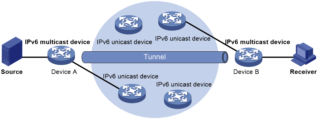
As shown in Figure 2, a tunnel is established between Device A and Device B. Device A encapsulates the IPv6 multicast data in unicast IPv6 packets, and forwards them to Device B across the tunnel through unicast devices. Then, Device B strips off the unicast IPv6 header and continues to forward the IPv6 multicast data down toward the receivers.
IPv6 mtrace
IPv6 mtrace uses mtrace2 to trace the path along which IPv6 multicast group data travels from a source to a destination.
Device roles
IPv6 mtrace includes the following roles:
· Last-hop router (LHR)—An LHR is a router that has an IPv6 multicast-enabled interface on the same subnet as the destination and can forward specific IPv6 multicast data to the subnet.
· First-hop router (FHR)—An FHR is a router that is directly connected to the IPv6 multicast source.
· Client—A client is a router that initiates an mtrace2.
Process
The IPv6 mtrace process is as follows:
1. The client sends an mtrace2 Query message (with a hops field indicating the maximum number of hops to be traced) to the destination.
2. The LHR turns the received Query message to an mtrace2 Request message by adding local forwarding information and sends the Request message to the upstream neighbor.
3. Each router along the traced path adds its local forwarding information to the received Request message and sends the Request message to its upstream neighbor.
4. The FHR adds its local forwarding information to the received Request message. Then, it turns the Request message to an mtrace2 Reply message and sends the Reply message to the client.
5. The client interprets forwarding information in the Reply message and displays the information.
IPv6 multicast routing and forwarding tasks at a glance
To configure IPv6 multicast routing and forwarding, perform the following tasks:
1. Enabling IPv6 multicast routing
2. (Optional.) Configuring static IPv6 multicast routes
3. (Optional.) Specifying the longest prefix match principle
4. (Optional.) Configuring IPv6 multicast load splitting
5. (Optional.) Configuring an IPv6 multicast forwarding boundary
6. (Optional.) Using mtrace2 to trace an IPv6 multicast path
7. (Optional.) Setting the maximum number of cached unknown IPv6 multicast packets
Prerequisites for IPv6 multicast routing and forwarding
Before you configure multicast routing and forwarding, configure an IPv6 unicast routing protocol so that all devices in the domain can interoperate at the network layer.
Enabling IPv6 multicast routing
About this task
Enable IPv6 multicast routing before you configure any Layer 3 IPv6 multicast functionality in the public network or VPN instance.
Procedure
1. Enter system view.
system-view
2. Enable IPv6 multicast routing and enter IPv6 MRIB view.
ipv6 multicast routing [ vpn-instance vpn-instance-name ]
By default, IPv6 multicast routing is disabled.
Configuring static IPv6 multicast routes
About this task
When configuring a static IPv6 multicast route for an IPv6 multicast source, you can specify an RPF interface or an RPF neighbor for the IPv6 multicast traffic from that source.
Restrictions and guidelines
Static IPv6 multicast routes take effect only on the IPv6 multicast devices on which they are configured, and will not be broadcast or redistributed to other devices.
Procedure
1. Enter system view.
system-view
2. Configure a static multicast route.
ipv6 rpf-route-static [ vpn-instance vpn-instance-name ] ipv6-source-address prefix-length { rpf-nbr-address | interface-type interface-number } [ preference preference ]
3. (Optional.) Delete all static IPv6 multicast routes.
delete ipv6 rpf-route-static [ vpn-instance vpn-instance-name ]
To delete a single static IPv6 multicast route, use the undo ip rpf-route-static command.
Specifying the longest prefix match principle
About this task
You can enable the device to use the longest prefix match principle for RPF route selection. For more information about RPF route selection, see "RPF check process."
Procedure
1. Enter system view.
system-view
2. Enter IPv6 MRIB view.
ipv6 multicast routing [ vpn-instance vpn-instance-name ]
3. Specify the longest prefix match principle for RPF route selection.
longest-match
By default, the route preference principle is used.
Configuring IPv6 multicast load splitting
About this task
You can enable the device to split multiple IPv6 multicast data flows on a per-source basis or on a per-source-and-group basis.
Procedure
1. Enter system view.
system-view
2. Enter IPv6 MRIB view.
ipv6 multicast routing [ vpn-instance vpn-instance-name ]
3. Configure IPv6 multicast load splitting.
load-splitting { source | source-group }
By default, IPv6 multicast load splitting is disabled.
Configuring an IPv6 multicast forwarding boundary
About this task
You can configure an interface as an IPv6 multicast forwarding boundary for an IPv6 multicast group range. The interface cannot receive or forward IPv6 multicast packets for the groups in the range.
Restrictions and guidelines
You do not need to enable IPv6 multicast routing before this configuration.
Procedure
1. Enter system view.
system-view
2. Enter interface view.
interface interface-type interface-number
3. Configure an IPv6 multicast forwarding boundary.
ipv6 multicast boundary { ipv6-group-address prefix-length | scope { scope-id | admin-local | global | organization-local | site-local } }
By default, an interface is not an IPv6 multicast forwarding boundary for any IPv6 multicast groups.
Using mtrace2 to trace an IPv6 multicast path
Restrictions and guidelines
For successful IPv6 mtrace, do not use a UDP port number used by other modules.
You must specify the same UDP port number on all devices on the traced path.
Procedure
1. Enter system view.
system-view
2. (Optional.) Specify the UDP port number used by IPv6 mtrace.
ipv6 mtrace-service port number
By default, IPv6 mtrace uses UDP port number 10240.
3. Use mtrace2 to trace an IPv6 multicast path.
mtrace v2 ipv6 [ vpn-instance vpn-instance-name ] { source-address | group-address } * [ destination address | port number | wait-time time | max-hop count ] * [ verbose ]
The UDP port number specified in this command must be the same as that specified in the mtrace-service port command.
Setting the maximum number of cached unknown IPv6 multicast packets
About this task
The device caches an IPv6 multicast packet for a period of time if no matching multicast forwarding entry is found for the packet. If a multicast forwarding entry is established for the packet within the time period, the device forwards the packet. This mechanism prevents the device from mistakenly dropping IPv6 multicast packets when the multicast forwarding entries for these packets are to be established.
You can set the maximum number of unknown IPv6 multicast packets that can be cached for an (S, G) entry, in total, or both.
Restrictions and guidelines
As a best practice, set the value in the ipv6 multicast forwarding-table cache-unknown total command to be far greater than the value in the ipv6 multicast forwarding-table cache-unknown per-entry command.
Procedure
1. Enter system view.
system-view
2. Set the maximum number of unknown IPv6 multicast packets that can be cached for an (S, G) entry.
ipv6 multicast forwarding-table cache-unknown per-entry per-entry-limit
By default, the device can cache only one unknown IPv6 multicast packet for an (S, G) entry.
3. Set the maximum number of unknown IPv6 multicast packets that can be cached in total.
ipv6 multicast forwarding-table cache-unknown total total-limit
By default, the device can cache 1024 unknown IPv6 multicast packets in total.
Display and maintenance commands for IPv6 multicast routing and forwarding
|
|
CAUTION: The reset commands might cause IPv6 multicast data transmission failures. |
Execute display commands in any view and reset commands in user view.
|
Task |
Command |
|
Display information about the interfaces maintained by the IPv6 MRIB. |
display ipv6 mrib [ vpn-instance vpn-instance-name ] interface [ interface-type interface-number ] |
|
Display IPv6 multicast boundary information. |
display ipv6 multicast [ vpn-instance vpn-instance-name ] boundary { group [ ipv6-group-address [ prefix-length ] ] | scope [ scope-id ] } [ interface interface-type interface-number ] |
|
Display IPv6 multicast fast forwarding entries. |
display ipv6 multicast [ vpn-instance vpn-instance-name ] fast-forwarding cache [ ipv6-source-address | ipv6-group-address ] * [ slot slot-number ] |
|
Display statistics for IPv6 multicast forwarding events. |
display ipv6 multicast [ vpn-instance vpn-instance-name ] forwarding event [ slot slot-number ] |
|
Display IPv6 multicast forwarding entries. |
display ipv6 multicast [ vpn-instance vpn-instance-name ] forwarding-table [ ipv6-source-address [ prefix-length ] | ipv6-group-address [ prefix-length ] | incoming-interface interface-type interface-number | outgoing-interface { exclude | include | match } interface-type interface-number | slot slot-number | statistics ] * |
|
Display IPv6 multicast routing entries. |
display ipv6 multicast [ vpn-instance vpn-instance-name ] routing-table [ ipv6-source-address [ prefix-length ] | ipv6-group-address [ prefix-length ] | incoming-interface interface-type interface-number | outgoing-interface { exclude | include | match } interface-type interface-number ] * |
|
Display static IPv6 multicast routing entries. |
display ipv6 multicast [ vpn-instance vpn-instance-name ] routing-table static [ ipv6-source-address [ prefix-length ] ] |
|
Display RPF information for an IPv6 multicast source. |
display ipv6 multicast [ vpn-instance vpn-instance-name ] rpf-info ipv6-source-address [ ipv6-group-address ] |
|
Clear IPv6 multicast fast forwarding entries. |
reset ipv6 multicast [ vpn-instance vpn-instance-name ] fast-forwarding cache { { ipv6-source-address | ipv6-group-address } * | all } [ slot slot-number ] |
|
Clear statistics for IPv6 multicast forwarding events. |
reset ipv6 multicast [ vpn-instance vpn-instance-name ] forwarding event |
|
Clear IPv6 multicast forwarding entries. |
reset ipv6 multicast [ vpn-instance vpn-instance-name ] forwarding-table { { ipv6-source-address [ prefix-length ] | ipv6-group-address [ prefix-length ] | incoming-interface { interface-type interface-number } } * | all } |
|
Clear IPv6 multicast routing entries. |
reset ipv6 multicast [ vpn-instance vpn-instance-name ] routing-table { { ipv6-source-address [ prefix-length ] | ipv6-group-address [ prefix-length ] | incoming-interface interface-type interface-number } * | all } |
|
|
NOTE: · When you clear an IPv6 multicast routing entry, the associated IPv6 multicast forwarding entry is also cleared. · When you clear an IPv6 multicast forwarding entry, the associated IPv6 multicast routing entry is also cleared. |
IPv6 multicast routing and forwarding configuration examples
Example: Configuring IPv6 multicast forwarding over a GRE tunnel
Network configuration
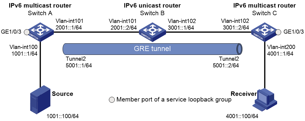
As shown in Figure 3:
· IPv6 multicast routing and IPv6 PIM-DM are enabled on Switch A and Switch C.
· Switch B does not support IPv6 multicast.
· Switch A, Switch B, and Switch C run OSPFv3. The source-side interface VLAN-interface 100 on Switch A does not run OSPFv3.
Configure the switches so that the receiver host can receive the IPv6 multicast data from Source.
Prerequisites
Assign an IPv6 address and prefix length to each interface as shown in Figure 3, and configure OSPFv3 on the switches (Do not run OSPFv3 on VLAN-interface 100 on Switch A.)
Procedure
1. Configure a GRE tunnel:
# Create a GRE tunnel interface Tunnel 2, and specify the tunnel mode as GRE/IPv6.
[SwitchA] interface tunnel 2 mode gre ipv6
# Assign an IPv6 address to interface Tunnel 2, and specify its source and destination addresses.
[SwitchA-Tunnel2] ipv6 address 5001::1 64
[SwitchA-Tunnel2] source 2001::1
[SwitchA-Tunnel2] destination 3001::2
[SwitchA-Tunnel2] quit
# Create a GRE tunnel interface Tunnel 2, and specify the tunnel mode as GRE/IPv6.
[SwitchC] interface tunnel 2 mode gre ipv6
# Assign an IPv6 address to interface Tunnel 2, and specify its source and destination addresses.
[SwitchC-Tunnel2] ipv6 address 5001::2 64
[SwitchC-Tunnel2] source 3001::2
[SwitchC-Tunnel2] destination 2001::1
[SwitchC-Tunnel2] quit
2. Enable IPv6 multicast routing, IPv6 PIM-DM, and MLD:
# On Switch A, enable IPv6 multicast routing, and enable IPv6 PIM-DM on each interface.
[SwitchA] ipv6 multicast routing
[SwitchA-mrib6] quit
[SwitchA] interface vlan-interface 100
[SwitchA-Vlan-interface100] ipv6 pim dm
[SwitchA-Vlan-interface100] quit
[SwitchA] interface vlan-interface 101
[SwitchA-Vlan-interface101] ipv6 pim dm
[SwitchA-Vlan-interface101] quit
[SwitchA] interface tunnel 2
[SwitchA-Tunnel2] ipv6 pim dm
[SwitchA-Tunnel2] quit
# On Switch C, enable IPv6 multicast routing.
[SwitchC] ipv6 multicast routing
[SwitchC-mrib6] quit
# Enable MLD on the receiver-side interface VLAN-interface 200.
[SwitchC] interface vlan-interface 200
[SwitchC-Vlan-interface200] mld enable
[SwitchC-Vlan-interface200] quit
# Enable IPv6 PIM-DM on VLAN-interface 102.
[SwitchC] interface vlan-interface 102
[SwitchC-Vlan-interface102] ipv6 pim dm
[SwitchC-Vlan-interface102] quit
[SwitchC] interface tunnel 2
[SwitchC-Tunnel2] ipv6 pim dm
[SwitchC-Tunnel2] quit
3. On Switch C, configure a static IPv6 route with the destination address 1001::1/64 and the outgoing interface Tunnel 2.
[SwitchC] ipv6 route-static 1001::1 64 tunnel 2
Verifying the configuration
# Send an MLD report from Receiver to join the IPv6 multicast group FF1E::101. (Details not shown.)
# Send IPv6 multicast data from Source to the IPv6 multicast group FF1E::101. (Details not shown.)
# Display IPv6 PIM routing entries on Switch C.
[SwitchC] display ipv6 pim routing-table
Total 1 (*, G) entry; 1 (S, G) entry
(*, FF1E::101)
Protocol: pim-dm, Flag: WC
UpTime: 00:04:25
Upstream interface: NULL
Upstream neighbor: NULL
RPF prime neighbor: NULL
Downstream interface(s) information:
Total number of downstreams: 1
1: Vlan-interface200
Protocol: mld, UpTime: 00:04:25, Expires: -
(1001::100, FF1E::101)
Protocol: pim-dm, Flag: ACT
UpTime: 00:06:14
Upstream interface: Tunnel2
Upstream neighbor: FE80::A01:101:1
RPF prime neighbor: FE80::A01:101:1
Downstream interface(s) information:
Total number of downstreams: 1
1: Vlan-interface200
Protocol: pim-dm, UpTime: 00:04:25, Expires: -
The output shows the following information:
· Switch A is the RPF neighbor of Switch C.
· IPv6 multicast data from Switch A is delivered over the GRE tunnel to Switch C.
Example: Changing an RPF route
Network configuration
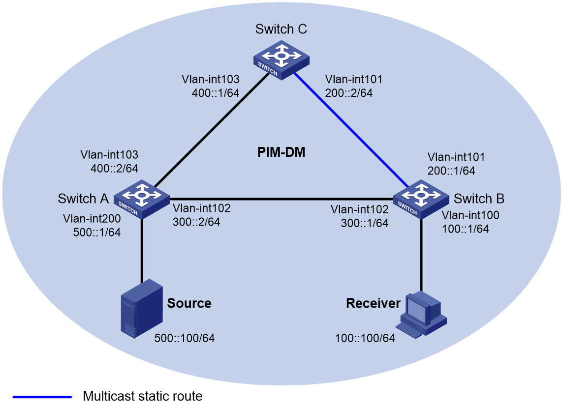
As shown in Figure 4:
· IPv6 PIM-DM runs on the network.
· All switches on the network support IPv6 multicast.
· Switch A, Switch B, and Switch C run OSPFv3.
· Typically, the receiver host can receive the IPv6 multicast data from the source through the path: Switch A to Switch B, which is the same as the unicast route.
Configure the switches so that the IPv6 multicast data from the source travels to the receiver along the following path: Switch A to Switch C to Switch B. This path is different from the unicast route.
Prerequisites
1. Assign an IP address and prefix length for each interface, as shown in Figure 4.
2. Configure OSPFv3 on the switches in the IPv6 PIM-DM domain.
Procedure
1. Enable IPv6 multicast routing, and enable MLD and IPv6 PIM-DM:
# On Switch B, enable IPv6 multicast routing.
<SwitchB> system-view
[SwitchB] ipv6 multicast routing
[SwitchB-mrib6] quit
# Enable MLD on the receiver-side interface VLAN-interface 100.
[SwitchB] interface vlan-interface 100
[SwitchB-Vlan-interface100] mld enable
[SwitchB-Vlan-interface100] quit
# Enable IPv6 PIM-DM on the other interfaces.
[SwitchB] interface vlan-interface 101
[SwitchB-Vlan-interface101] ipv6 pim dm
[SwitchB-Vlan-interface101] quit
[SwitchB] interface vlan-interface 102
[SwitchB-Vlan-interface102] ipv6 pim dm
[SwitchB-Vlan-interface102] quit
# On Switch A, enable IPv6 multicast routing.
<SwitchA> system-view
[SwitchA] ipv6 multicast routing
[SwitchA-mrib6] quit
# Enable IPv6 PIM-DM on each interface.
[SwitchA] interface vlan-interface 200
[SwitchA-Vlan-interface200] ipv6 pim dm
[SwitchA-Vlan-interface200] quit
[SwitchA] interface vlan-interface 102
[SwitchA-Vlan-interface102] ipv6 pim dm
[SwitchA-Vlan-interface102] quit
[SwitchA] interface vlan-interface 103
[SwitchA-Vlan-interface103] ipv6 pim dm
[SwitchA-Vlan-interface103] quit
# Enable IPv6 multicast routing and IPv6 PIM-DM on Switch C in the same way Switch A is configured. (Details not shown.)
2. Display RPF information for the source on Switch B.
[SwitchB] display ipv6 multicast rpf-info 500::100
RPF information about source 500::100:
RPF interface: Vlan-interface102, RPF neighbor: 300::2
Referenced prefix/prefix length: 500::/64
Referenced route type: igp
Route selection rule: preference-preferred
Load splitting rule: disable
Source AS: 0
C-multicast route target: 0x0000000000000000
The output shows that the current RPF route on Switch B is contributed by a unicast routing protocol and the RPF neighbor is Switch A.
3. On Switch B, configure a static IPv6 multicast route to the source and specify Switch C as the RPF neighbor.
[SwitchB] ipv6 rpf-route-static 500::100 64 200::2
Verifying the configuration
# Display RPF information for the source on Switch B.
[SwitchB] display ipv6 multicast rpf-info 500::100
RPF information about source 500::100:
RPF interface: Vlan-interface101, RPF neighbor: 200::2
Referenced prefix/prefix length: 500::/64
Referenced route type: multicast static
Route selection rule: preference-preferred
Load splitting rule: disable
Source AS: 0
C-multicast route target: 0x0000000000000000
The output shows the following information:
· The RPF route on Switch B is the configured static IPv6 multicast route.
· The RPF neighbor of Switch B is Switch C.
Example: Creating an RPF route
Network configuration
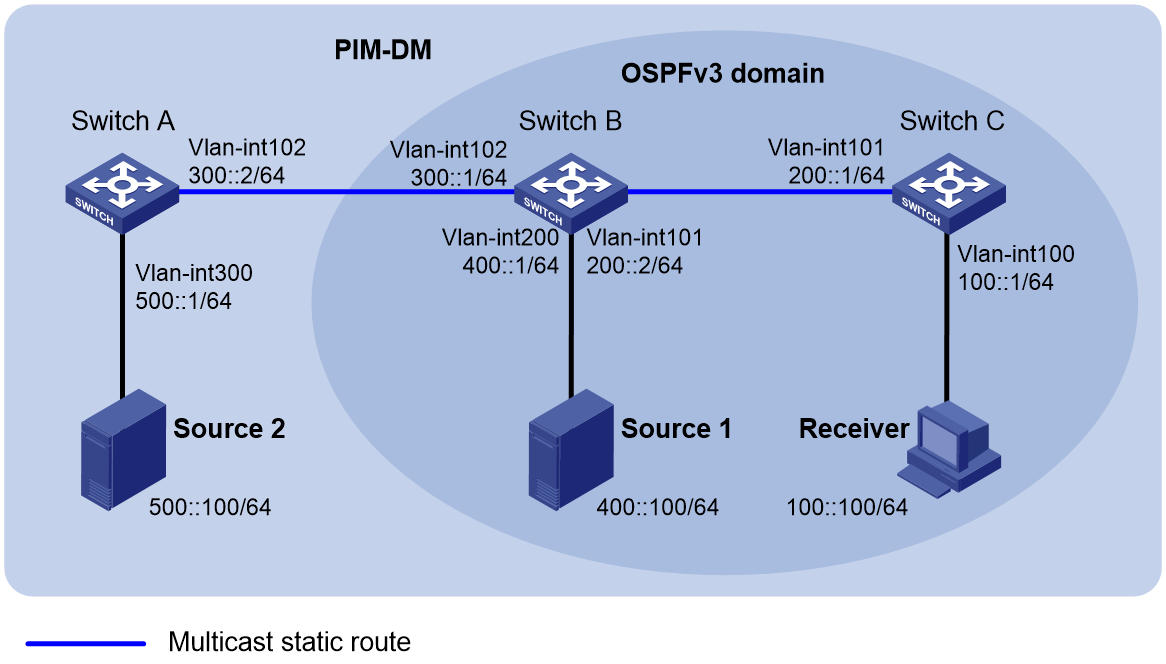
As shown in Figure 5:
· IPv6 PIM-DM runs on the network.
· All switches on the network support IP multicast.
· Switch B and Switch C run OSPFv3, and have no unicast routes to Switch A.
· Typically, the receiver host receives the IPv6 multicast data from the source 1 in the OSPFv3 domain.
Configure the switches so that the receiver host can receive IPv6 multicast data from Source 2, which is outside the OSPFv3 domain.
Prerequistes
1. Assign an IP address and subnet mask for each interface, as shown in Figure 5.
2. Configure OSPFv3 on Switch B and Switch C.
Procedure
1. Enable IPv6 multicast routing, and enable MLD and IPv6 PIM-DM:
# On Switch C, enable IPv6 multicast routing.
<SwitchC> system-view
[SwitchC] ipv6 multicast routing
[SwitchC-mrib6] quit
# Enable MLD on the receiver-side interface VLAN-interface 100.
[SwitchC] interface vlan-interface 100
[SwitchC-Vlan-interface100] mld enable
[SwitchC-Vlan-interface100] quit
# Enable IPv6 PIM-DM on VLAN-interface 101.
[SwitchC] interface vlan-interface 101
[SwitchC-Vlan-interface101] ipv6 pim dm
[SwitchC-Vlan-interface101] quit
# On Switch A, enable IPv6 multicast routing.
<SwitchA> system-view
[SwitchA] ipv6 multicast routing
[SwitchA-mrib6] quit
# Enable IPv6 PIM-DM on each interface.
[SwitchA] interface vlan-interface 300
[SwitchA-Vlan-interface300] ipv6 pim dm
[SwitchA-Vlan-interface300] quit
[SwitchA] interface vlan-interface 102
[SwitchA-Vlan-interface102] ipv6 pim dm
[SwitchA-Vlan-interface102] quit
# Enable IPv6 multicast routing and IPv6 PIM-DM on Switch B in the same way Switch A is configured. (Details not shown.)
2. Display RPF information for Source 2 on Switch B and Switch C.
[SwitchB] display ipv6 multicast rpf-info 500::100
[SwitchC] display ipv6 multicast rpf-info 500::100
No output is displayed because no RPF routes to Source 2 exist on Switch B and Switch C.
3. Configure a static IPv6 multicast route:
# Configure a static IPv6 multicast route on Switch B and specify Switch A as its RPF neighbor to Source 2.
[SwitchB] ipv6 rpf-route-static 500::100 64 300::2
# Configure a static IPv6 multicast route on Switch C and specify Switch B as its RPF neighbor to Source 2.
[SwitchC] ipv6 rpf-route-static 500::100 64 200::2
Verifying the configuration
# Display RPF information for Source 2 on Switch B.
[SwitchB] display ipv6 multicast rpf-info 500::100
RPF information about source 50::100:
RPF interface: Vlan-interface102, RPF neighbor: 300::2
Referenced prefix/prefix length: 500::/64
Referenced route type: multicast static
Route selection rule: preference-preferred
Load splitting rule: disable
Source AS: 0
C-multicast route target: 0x0000000000000000
# Display RPF information for Source 2 on Switch C.
[SwitchC] display ipv6 multicast rpf-info 500::100
RPF information about source 500::100:
RPF interface: Vlan-interface101, RPF neighbor: 200::2
Referenced prefix/prefix length: 500::/64
Referenced route type: multicast static
Route selection rule: preference-preferred
Load splitting rule: disable
Source AS: 0
C-multicast route target: 0x0000000000000000
The output shows that the RPF routes to Source 2 exist on Switch B and Switch C. These RPF routes are the configured static IPv6 multicast routes.
