- Table of Contents
-
- 06-Layer 3—IP Routing Configuration Guide
- 00-Preface
- 01-Basic IP routing configuration
- 02-Static routing configuration
- 03-OSPF configuration
- 04-IS-IS configuration
- 05-Basic BGP configuration
- 06-Advanced BGP configuration
- 07-Policy-based routing configuration
- 08-IPv6 static routing configuration
- 09-OSPFv3 configuration
- 10-IPv6 policy-based routing configuration
- 11-Routing policy configuration
- 12-DCN configuration
- Related Documents
-
| Title | Size | Download |
|---|---|---|
| 01-Basic IP routing configuration | 185.40 KB |
Contents
Extension attribute redistribution
Enabling IPv4 bandwidth-based load sharing
Enabling symmetric load sharing
Verifying and maintaining load sharing
Setting the maximum lifetime for routes and labels in the RIB
Setting the maximum lifetime for routes in the FIB
Enabling the RIB to flush route attribute information to the FIB
Enabling the enhanced ECMP mode
Restrictions and guidelines for enabling the enhanced ECMP mode
Enabling the IPv4 and IPv6 enhanced ECMP mode
Configuring inter-protocol FRR
Configuring BFD for primary route next hop availability detection
About configuring BFD for primary route next hop availability detection
Restrictions and guidelines for configuring BFD for primary route next hop availability detection
Configuring BFD control packet mode
Configuring BFD echo packet mode
Enabling route fast switchover
Configuring routing policy-based recursive lookup
Configuring next hop recursion loop suppression
About next hop recursion loop suppression
Restrictions and guidelines for configuring next hop recursion loop suppression
Disabling suppression for next hop recursion loop (IPv4)
Setting the interval for clearing the recursion loop counter (IPv4)
Disabling suppression for next hop recursion loop (IPv6)
Setting the interval for clearing the recursion loop counter (IPv6)
Setting the maximum number of active routes supported by the device
Setting the maximum number of RIB next hop records or route entry records
Configuring and displaying the hardware resource mode
Configuring the routing-mode hardware resource mode
Displaying the routing-mode hardware resource mode
Verifying and maintaining basic IP routing (IPv4)
Displaying IPv4 routing table information
Displaying ECMP route information
Displaying IPv4 RIB information
Displaying and clearing IPv4 routing table statistics
Displaying and clearing IPv4 route entry records
Displaying and clearing next hop records in the RIB
Verifying and maintaining basic IP routing (IPv6)
Displaying IPv6 routing table information
Displaying IPv6 ECMP route information
Displaying IPv6 RIB information
Displaying and clearing IPv6 routing table statistics
Displaying and clearing IPv6 route entry records
Displaying and clearing next hop records in the IPv6 RIB
Basic IP routing configuration examples
Example: Configuring load sharing based on source and destination addresses
Configuring basic IP routing
About IP routing
IP routing directs IP packet forwarding on routers. Based on the destination IP address in the packet, a router looks up a route for the packet in a routing table and forwards the packet to the next hop. Routes are path information used to direct IP packets.
Routing table
A RIB contains the global routing information and related information, including route recursion, route redistribution, and route extension information. The router selects optimal routes from the routing table and puts them into the FIB table. It uses the FIB table to forward packets. For more information about the FIB table, see Layer 3—IP Services Configuration Guide.
Route categories
Table 1 categorizes routes by different criteria.
|
Criterion |
Categories |
|
Origin |
· Direct route—A direct route is discovered by the data link protocol on an interface, and is also called an interface route. · Static route—A static route is manually configured by an administrator. · Dynamic route—A dynamic route is dynamically discovered by a routing protocol. |
|
Destination |
· Network route—The destination is a network. The subnet mask is less than 32 bits. · Host route—The destination is a host. The subnet mask is 32 bits. |
|
Whether the destination is directly connected |
· Direct route—The destination is directly connected. · Indirect route—The destination is indirectly connected. |
Dynamic routing protocols
Static routes work well in small, stable networks. They are easy to configure and require fewer system resources. However, in networks where topology changes occur frequently, a typical practice is to configure a dynamic routing protocol. Compared with static routing, a dynamic routing protocol is complicated to configure, requires more router resources, and consumes more network resources.
Dynamic routing protocols dynamically collect and report reachability information to adapt to topology changes. They are suitable for large networks.
Dynamic routing protocols can be classified by different criteria, as shown in Table 2.
Table 2 Categories of dynamic routing protocols
|
Criterion |
Categories |
|
Operation scope |
· IGPs—Work within an AS. Examples include OSPF and IS-IS. · EGPs—Work between ASs. The most popular EGP is BGP. |
|
Routing algorithm |
· Distance-vector protocols—Examples include BGP. BGP is also considered a path-vector protocol. · Link-state protocols—Examples include OSPF and IS-IS. |
|
Destination address type |
· Unicast routing protocols—Examples include OSPF, BGP, and IS-IS. · Multicast routing protocols—Examples include PIM-SM and PIM-DM. The protocols are not supported in the current software version. |
|
IP version |
· IPv4 routing protocols—Examples include OSPF, BGP, and IS-IS. · IPv6 routing protocols—Examples include OSPFv3, IPv6 BGP, and IPv6 IS-IS. |
An AS refers to a group of routers that use the same routing policy and work under the same administration.
Route preference
Routing protocols, including static and direct routing, each by default have a preference. If they find multiple routes to the same destination, the router selects the route with the highest preference as the optimal route.
The preference of a direct route is always 0 and cannot be changed. You can configure a preference for each static route and each dynamic routing protocol. The following table lists the route types and default preferences. The smaller the value, the higher the preference.
Table 3 Route types and default route preferences
|
Route type |
Preference |
|
Direct route |
0 |
|
OSPF |
10 |
|
IS-IS |
15 |
|
Unicast static route |
60 |
|
OSPF ASE |
150 |
|
OSPF NSSA |
150 |
|
IBGP |
255 |
|
EBGP |
255 |
|
Unknown (route from an untrusted source) |
256 |
Load sharing
A routing protocol might find multiple optimal equal-cost routes to the same destination. You can use these routes to implement equal-cost multi-path (ECMP) load sharing.
Static routing, IPv6 static routing, OSPF, OSPFv3, BGP, IPv6 BGP, IS-IS, and IPv6 IS-IS support ECMP load sharing.
Route backup
Route backup can improve network availability. Among multiple routes to the same destination, the route with the highest priority is the primary route and others are secondary routes.
The router forwards matching packets through the primary route. When the primary route fails, the route with the highest preference among the secondary routes is selected to forward packets. When the primary route recovers, the router uses it to forward packets.
Route recursion
To use a BGP or static route that has an indirectly connected next hop, a router must perform route recursion to find the output interface to reach the next hop.
Link-state routing protocols, such as OSPF and IS-IS, do not need route recursion, because they obtain directly connected next hops through route calculation.
The RIB records and saves route recursion information, including brief information about related routes, recursive paths, and recursion depth.
Route redistribution
Route redistribution enables routing protocols to learn routing information from each other. A dynamic routing protocol can redistribute routes from other routing protocols, including direct and static routing. For more information, see the respective chapters on those routing protocols in this configuration guide.
The RIB records redistribution relationships of routing protocols.
Extension attribute redistribution
Extension attribute redistribution enables routing protocols to learn route extension attributes from each other, including BGP extended community attributes, OSPF area IDs, route types, and router IDs.
The RIB records extended attributes of each routing protocol and redistribution relationships of different routing protocol extended attributes.
Configuring load sharing
Configuring load sharing mode
About this task
Load sharing can be implemented on a per-flow basis.
In the per-flow load sharing mode, the device forwards flows over equal-cost routes. Packets of one flow travel along the same routes. You can configure the device to identify a flow based on the following criteria: source IP address, destination IP address, source port number, destination port number, IP protocol number, and input interface.
In a complex network, when the criteria cannot distinguish flows, you can use the algorithm keyword to specify an algorithm to identify flows.
Procedure
1. Enter system view.
system-view
2. Configure load sharing.
ip load-sharing mode per-flow [ algorithm algorithm-number [ seed seed-number ] [ shift shift-number ] | [ dest-ip | dest-port | flow-label | ingress-port | ip-pro | src-ip | src-port ] * ] { global | slot slot-number }
The device performs per-flow load sharing based on the following criteria: source IP address, destination IP address, source port number, destination port number, IP protocol number, and ingress port.
Enabling IPv4 bandwidth-based load sharing
About this task
This feature load shares flow traffic among multiple output interfaces based on their load percentages. The device calculates the load percentage for each output interface in terms of the interface expected bandwidth.
Devices that run load sharing protocols implement load sharing based on the ratios defined by these protocols.
Restrictions and guidelines
This feature cannot take effect when IPv4 or IPv6 enhanced ECMP mode is enabled.
Procedure
1. Enter system view.
system-view
2. Enable IPv4 bandwidth-based load sharing.
bandwidth-based-sharing
By default, the IPv4 bandwidth-based load sharing is disabled.
3. (Optional.) Configure the expected bandwidth of the interface.
a. Enter interface view.
interface interface-type interface-number
b. Configure the expected bandwidth of the interface.
bandwidth bandwidth
By default, the expected bandwidth is the physical bandwidth of the interface.
Enabling symmetric load sharing
About this task
Symmetric load sharing ensures that bidirectional traffic specific to a source and destination address pair flow along the same path.
Procedure
1. Enter system view.
system-view
2. Enable symmetric load sharing.
ip load-sharing symmetric enable
By default, symmetric load sharing is disabled.
Verifying and maintaining load sharing
Perform display tasks in any view.
· Display the load sharing mode in use.
display ip load-sharing mode slot slot-number
· Display the load sharing path selected for a flow.
display ip load-sharing path ingress-port interface-type interface-number packet-format { ipv4oe dest-ip ip-address [ src-ip ip-address ] | ipv6oe dest-ipv6 ipv6-address [ flow-label flow-label | src-ipv6 ipv6-address ] * } [ dest-port port-id | ip-pro protocol-id | src-port port-id | vpn-instance vpn-instance-name ] *
This command takes effect only on the S9825 switch series.
Setting the maximum lifetime for routes and labels in the RIB
About this task
Perform this task to prevent routes of a certain protocol from being aged out due to slow protocol convergence resulting from a large number of route entries or long GR period.
Restrictions and guidelines for setting the maximum lifetime for routes and labels in the RIB
The configuration takes effect at the next protocol or RIB process switchover.
Procedure (IPv4)
1. Enter system view.
system-view
2. Enter RIB view.
rib
3. Create the RIB IPv4 address family and enter its view.
address-family ipv4
4. Set the maximum lifetime for IPv4 routes and labels in the RIB.
protocol protocol [ instance instance-name ] lifetime seconds
By default, the maximum lifetime for routes and labels in the RIB is 900 seconds.
Procedure (IPv6)
1. Enter system view.
system-view
2. Enter RIB view.
rib
3. Create the RIB IPv6 address family and enter its view.
address-family ipv6
4. Set the maximum lifetime for IPv6 routes and labels in the RIB.
protocol protocol [ instance instance-name ] lifetime seconds
By default, the maximum lifetime for routes and labels in the RIB is 900 seconds.
Setting the maximum lifetime for routes in the FIB
About this task
When GR is disabled, FIB entries must be retained for some time after a protocol process switchover or RIB process switchover. When GR is enabled, FIB entries must be removed immediately after a protocol or RIB process switchover to avoid routing issues. Perform this task to meet such requirements.
Procedure (IPv4)
1. Enter system view.
system-view
2. Enter RIB view.
rib
3. Create the RIB IPv4 address family and enter its view.
address-family ipv4
4. Set the maximum lifetime for IPv4 routes in the FIB.
fib lifetime seconds
By default, the maximum lifetime for routes in the FIB is 600 seconds.
Procedure (IPv6)
1. Enter system view.
system-view
2. Enter RIB view.
rib
3. Create the RIB IPv6 address family and enter its view.
address-family ipv6
4. Set the maximum lifetime for IPv6 routes in the FIB.
fib lifetime seconds
By default, the maximum lifetime for routes in the FIB is 600 seconds.
Enabling the RIB to flush route attribute information to the FIB
1. Enter system view.
system-view
2. Enter RIB view.
rib
3. Create the RIB IPv4 address family and enter its view.
address-family ipv4
4. Enable the RIB to flush route attribute information to the FIB.
flush route-attribute protocol
By default, the RIB does not flush route attribute information to the FIB.
Enabling the enhanced ECMP mode
About enhanced ECMP mode
When one or multiple ECMP routes fail, the default ECMP mode enables the device to reallocate all traffic to the remaining routes.
The enhanced ECMP mode enables the device to reallocate only the traffic of the failed routes to the remaining routes, which ensures forwarding continuity.
Restrictions and guidelines for enabling the enhanced ECMP mode
This configuration takes effect at reboot. Make sure the reboot does not impact your network.
Enabling the IPv4 and IPv6 enhanced ECMP mode
1. Enter system view.
system-view
2. Enable the IPv4 and IPv6 enhanced ECMP mode.
ecmp mode enhanced
By default, the IPv4 and IPv6 enhanced ECMP mode is disabled.
Configuring inter-protocol FRR
About this task
Inter-protocol fast reroute (FRR) enables fast rerouting between routes of different protocols. A backup next hop is automatically selected to reduce the service interruption time caused by unreachable next hops. When the next hop of the primary link fails, the traffic is redirected to the backup next hop.
Among the routes to the same destination in the RIB, a router adds the route with the highest preference to the FIB table. For example, if a static route and an OSPF route in the RIB have the same destination, the router adds the OSPF route to the FIB table by default. The next hop of the static route is selected as the backup next hop for the OSPF route. When the next hop of the OSPF route is unreachable, the backup next hop is used.
Restrictions and guidelines for inter-protocol FRR
This feature uses the next hop of a route from a different protocol as the backup next hop, which might cause loops.
Procedure (IPv4)
1. Enter system view.
system-view
2. Enter RIB view.
rib
3. Create the RIB IPv4 address family and enter its view.
address-family ipv4
4. Enable IPv4 RIB inter-protocol FRR.
inter-protocol fast-reroute [ vpn-instance vpn-instance-name ]
By default, inter-protocol FRR is disabled.
If you do not specify a VPN instance, inter-protocol FRR is enabled for the public network.
Procedure (IPv6)
1. Enter system view.
system-view
2. Enter RIB view.
rib
3. Create the RIB IPv6 address family and enter its view.
address-family ipv6
4. Enable IPv6 RIB inter-protocol FRR.
inter-protocol fast-reroute [ vpn-instance vpn-instance-name ]
By default, inter-protocol FRR is disabled.
If you do not specify a VPN instance, inter-protocol FRR is enabled for the public network.
Configuring BFD for primary route next hop availability detection
About configuring BFD for primary route next hop availability detection
This feature uses BFD to detect the availability of the primary route next hop for inter-protocol FRR or ECMP routes. When the primary route next hop is unreachable, this feature enables the upper layer routing protocol to reallocate service traffic to the backup next hops or to the remaining ECMP next hops.
For inter-protocol FRR, the primary route is the route with the highest preference among the routes to the same destination. If BFD detects that the next hop of the primary route is unreachable, it notifies the FIB of the issue. The FIB will use the backup next hops to guide traffic forwarding.
For ECMP routes of a routing protocol, the primary route is each ECMP route. If BFD detects that the next hop of an ECMP route is unreachable, it notifies the routing protocol of the issue. The routing protocol will reallocate the service traffic to the remaining ECMP next hops. When BFD detects that the next hops of all ECMP routes are invalid, BFD notifies the routing protocol to withdraw the routes. In addition, the device reselects optimal routes for the service traffic.
For more information about BFD, see High Availability Configuration Guide.
Restrictions and guidelines for configuring BFD for primary route next hop availability detection
This feature takes effect and automatically creates a BFD session only when the primary route exists and a backup next hop is generated for it.
If you specify the ecmp-shared keyword when configuring FRR for a routing protocol, the device will use the LFA algorithm to calculate backup next hops for each ECMP route. The routes destined for the backup next hops are also added to the routing table as ECMP routes and the state of these routes is backup. BFD does not detect these backup ECMP routes.
Configuring BFD control packet mode
About this task
This mode uses BFD control packets to detect the status of a link bidirectionally at a millisecond level.
Restrictions and guidelines for BFD control packet mode
A control-packet-mode BFD session can be successfully established through negotiation between the two ends. To use a control-packet-mode BFD session to detect the primary route next hop availability, you must create a static BFD session that meets the following requirements on the next hop device:
· Create a single-hop BFD session in control packet mode.
· The source IP address of the BFD session is the destination IP address of the BFD session automatically created by the local end.
· The destination IP address of the BFD session is the source IP address of the BFD session automatically created by the local end.
· The remote discriminator of the BFD session is the local discriminator of the BFD session automatically created by the local end.
The local device can use a control-packet-mode BFD session to detect the primary route next hop only after you create the static BFD session on the primary route next hop device.
Procedure
1. Enter system view.
system-view
2. Enter RIB view.
rib
3. Create RIB IPv4 or IPv6 address family view and enter the view.
IPv4:
address-family ipv4
IPv6:
address-family ipv6
4. Enable BFD for primary route next hop availability detection.
primary-path-detect bfd ctrl [ inter-protocol-frr | protocol-ecmp protocol ]
By default, BFD is disabled for primary route next hop availability detection.
Configuring BFD echo packet mode
About this task
With BFD echo packet mode enabled, the output interface sends BFD echo packets to the destination device, and the device sends the packets back to test the link reachability.
Restrictions and guidelines
You do not need to configure BFD echo packet mode at the peer end.
Procedure
1. Enter system view.
system-view
2. (Optional.) Configure the source IP address of echo packets.
IPv4:
bfd echo-source-ip ip-address
By default, the source IPv4 address of echo packets is not configured.
As a best practice to avoid network congestion caused by excessive ICMP redirect packets from the peer, use this command. Make sure the source IPv4 address is not on the subnet of any interfaces on the device.
For more information about this command, see BFD in High Availability Command Reference.
IPv6:
bfd echo-source-ipv6 ipv6-address
By default, the source IPv6 address of echo packets is not configured.
As a best practice to avoid network congestion caused by excessive ICMPv6 redirect packets from the peer, use this command. Make sure the source IPv6 address is not on the subnet of any interfaces on the device.
You must specify a global unicast address as the source IPv6 address of BFD echo packets.
For more information about this command, see BFD in High Availability Command Reference.
3. Enter RIB view.
rib
4. Create RIB IPv4 or IPv6 address family view and enter the view.
IPv4:
address-family ipv4
IPv6:
address-family ipv6
5. Enable BFD for primary route next hop availability detection.
primary-path-detect bfd echo [ inter-protocol-frr | protocol-ecmp protocol ]
By default, BFD is disabled for primary route next hop availability detection.
Enabling route fast switchover
About this task
This feature applies to a device that provides the same physical output interface for large numbers of routes, including ECMP routes and primary/secondary routes. When a link failure occurs on the interface, the device must perform the following tasks before switching the traffic to another route:
1. Deletes all ARP or ND entries for the link.
2. Instructs the FIB to delete the associated FIB entries.
This procedure is time consuming and interrupts traffic for a long time. To resolve this issue, you can enable route fast switchover. This feature allows the device to instruct the FIB to delete the invalid FIB entries for route switchover first.
Procedure (IPv6)
1. Enter system view.
system-view
2. Enable IPv6 route fast switchover.
ipv6 route fast-switchover enable
By default, IPv6 route fast switchover is disabled.
Configuring routing policy-based recursive lookup
About this task
Configure routing policy-based recursive lookup to control route recursion results. For example, when a route changes, the routing protocol has to perform a route recursion if the next hop is indirectly connected. The routing protocol might select an incorrect path, which can cause traffic loss. To prevent this problem, you can use a routing policy to filter out incorrect routes. The routes that pass the filtering of the routing policy will be used for route recursion.
Restrictions and guidelines for routing policy-based recursive lookup
The apply clauses in the specified routing policy cannot take effect.
Make sure a minimum of one related route can match the routing policy for correct traffic forwarding.
Procedure (IPv4)
1. Enter system view.
system-view
2. Enter RIB view.
rib
3. Create the RIB IPv4 address family and enter its view.
address-family ipv4
4. Configure routing policy-based recursive lookup.
protocol protocol nexthop recursive-lookup route-policy route-policy-name
By default, routing policy-based recursive lookup is not configured.
Procedure (IPv6)
1. Enter system view.
system-view
2. Enter RIB view.
rib
3. Create the RIB IPv6 address family and enter its view.
address-family ipv6
4. Configure routing policy-based recursive lookup.
protocol protocol nexthop recursive-lookup route-policy route-policy-name
By default, routing policy-based recursive lookup is not configured.
Configuring next hop recursion loop suppression
About next hop recursion loop suppression
A recursion loop occurs when a route recurses to a related route that recurses back to the route. It causes a route recursion failure and further lookup for a related route. If recursion loop persists, continuous route flapping will cause high system resource consumption and CPU utilization.
This feature enables the system to use a counter to record the number of route recursion failures. When the counter reaches 20, the system suppresses route recursion for a specified period of time to save system resources on the device.
Restrictions and guidelines for configuring next hop recursion loop suppression
The configuration of disabling next hop recursion loop suppression takes effect immediately.
The setting of clearing the recursion loop counter takes effect for the next recursion loop suppression.
Disabling suppression for next hop recursion loop (IPv4)
1. Enter system view.
system-view
2. Enter RIB view.
rib
3. Create the RIB IPv4 address family and enter its view.
address-family ipv4
4. Disable next hop recursion loop suppression.
nexthop recursive-lookup restrain disable
By default, next hop recursion loop suppression is enabled.
Setting the interval for clearing the recursion loop counter (IPv4)
1. Enter system view.
system-view
2. Enter RIB view.
rib
3. Create the RIB IPv4 address family and enter its view.
address-family ipv4
4. Set the interval for clearing the recursion loop counter.
nexthop recursive-lookup restrain clear-interval interval
By default, the interval for clearing the recursion loop counter is 600 seconds.
Disabling suppression for next hop recursion loop (IPv6)
1. Enter system view.
system-view
2. Enter RIB view.
rib
3. Create the RIB IPv6 address family and enter its view.
address-family ipv6
4. Disable next hop recursion loop suppression.
nexthop recursive-lookup restrain disable
By default, next hop recursion loop suppression is enabled.
Setting the interval for clearing the recursion loop counter (IPv6)
1. Enter system view.
system-view
2. Enter RIB view.
rib
3. Create the RIB IPv6 address family and enter its view.
address-family ipv6
4. Set the interval for clearing the recursion loop counter.
nexthop recursive-lookup restrain clear-interval interval
By default, the interval for clearing the recursion loop counter is 600 seconds.
Setting the maximum number of active routes supported by the device
About this task
The feature allows you to set the maximum number of active IPv4/IPv6 routes supported by the device.
· You can use the routing-table limit number warn-threshold command to specify an alarm threshold. When the percentage of active routes exceeds the alarm threshold, the system generates a system log message but still accepts active routes. You can take relevant actions based on the message to save system resources. If the number of active routes reaches the maximum number, no more routes can be added and new routes are discarded.
· You can use the routing-table limit number simply-alert command to specify an alarm threshold. When the maximum number of active IPv4/IPv6 routes is exceeded, the device still accepts new active routes but generates a system log message. You can take relevant actions based on the message to save system resources.
Procedure (IPv4)
1. Enter system view.
system-view
2. Enter RIB view.
rib
3. Create the RIB IPv4 address family and enter its view.
address-family ipv4
4. Set the maximum number of active IPv4 routes supported by the device.
routing-table limit number { warn-threshold | simply-alert }
By default, the maximum number of active IPv4 routes is not set for the device.
Configuration in RIB IPv4 address family view limits the number of active IPv4 routes for the public network and all VPN instances.
Procedure (IPv6)
1. Enter system view.
system-view
2. Enter RIB view.
rib
3. Create the RIB IPv6 address family and enter its view.
address-family ipv6
4. Set the maximum number of active IPv6 routes supported by the device.
routing-table limit number { warn-threshold | simply-alert }
By default, the maximum number of active IPv6 routes is not set for the device.
Configuration in RIB IPv6 address family view limits the number of active IPv6 routes for the public network and all VPN instances.
Setting the maximum number of RIB next hop records or route entry records
About this task
When adding, modifying, or deleting RIP next hops or route entries, the device records associated information to facilitate troubleshooting. To view the recorded information, execute the display rib nib record command.
As a best practice to avoid excessive system resource usage, set the maximum number of RIB next hop records or route entry records properly. When the maximum number is reached, the device can continue to record new information. The new records will overwrite the earliest records.
Procedure (IPv4)
1. Enter system view.
system-view
2. Enter RIB view.
rib
3. Create the RIB IPv4 address family and enter its view.
address-family ipv4
4. Set the maximum number of RIB next hop records or route entry records.
record-limit limit [ rib nib [ flush [ delete | update ] | receive [ add | delete | update ] ] ]
record-limit limit [ routing-table [ flush [ delete | update ] | notify [ delete | update ] | receive [ add | delete | update ] ] ]
By default, the maximum number of RIB next hop records or route entry records is 1000.
Procedure (IPv6)
1. Enter system view.
system-view
2. Enter RIB view.
rib
3. Create the RIB IPv6 address family and enter its view.
address-family ipv6
4. Set the maximum number of IPv6 RIB next hop records or route entry records.
record-limit limit [ rib nib [ flush [ delete | update ] | receive [ add | delete | update ] ] ]
record-limit limit [ routing-table [ flush [ delete | update ] | notify [ delete | update ] | receive [ add | delete | update ] ] ]
By default, the maximum number of IPv6 RIB next hop records or route entry records is 1000.
Configuring and displaying the hardware resource mode
Configuring the routing-mode hardware resource mode
About this task
This command takes effect after you reboot the device. Before you reboot the device, make sure you understand the potential impact on the network.
Table 4 Support of routing-mode hardware resource modes for route types
|
Routing-mode hardware resource mode |
Route type |
|
IPv6-128 mode |
Supports IPv6 routes with more than 64 bits. |
Procedure
1. Enter system view.
system-view
2. Set the routing-mode hardware resource mode.
hardware-resource routing-mode ipv6-128
By default, the routing-mode hardware resource mode is IPv6-128.
Displaying the routing-mode hardware resource mode
Execute the following command in any view to display the routing-mode hardware resource mode.
display hardware-resource [ routing-mode ]
Verifying and maintaining basic IP routing (IPv4)
Displaying IPv4 routing table information
Perform display tasks in any view.
· Display routing table information.
display ip routing-table [ all-vpn-instance | vpn-instance vpn-instance-name ] [ verbose ]
display ip routing-table all-routes
· Display information about routes permitted by an IPv4 basic ACL.
display ip routing-table [ vpn-instance vpn-instance-name ] acl ipv4-acl-number [ verbose ]
· Display information about routes to a specific destination address.
display ip routing-table [ vpn-instance vpn-instance-name ] ip-address [ mask-length | mask ] [ longer-match ] [ verbose ]
· Display information about routes to a range of destination addresses.
display ip routing-table [ vpn-instance vpn-instance-name ] ip-address1 to ip-address2 [ verbose ]
· Display information about routes permitted by an IP prefix list.
display ip routing-table [ vpn-instance vpn-instance-name ] prefix-list prefix-list-name [ verbose ]
· Display information about routes installed by a protocol.
display ip routing-table [ vpn-instance vpn-instance-name ] protocol protocol [ inactive | verbose ]
· Display brief routing table information, including maximum number of ECMP routes, maximum number of active routes, and number of remaining active routes.
display ip routing-table [ vpn-instance vpn-instance-name ] summary
Displaying ECMP route information
To display ECMP mode information, execute the following command in any view:
display ecmp mode
Displaying IPv4 RIB information
Perform display tasks in any view.
· Display route attribute information in the RIB.
display rib attribute [ attribute-id ]
· Display RIB GR state information.
display rib graceful-restart
· Display next hop information in the RIB.
display rib nib [ self-originated ] [ nib-id ] [ verbose ]
display rib nib [ sub-nib nib-id ] [ verbose ]
display rib nib protocol protocol [ verbose ]
· Display next hop information for direct routes.
display route-direct nib [ nib-id ] [ verbose ]
Displaying and clearing IPv4 routing table statistics
To display IPv4 route or route prefix statistics, execute the following command in any view:
display ip routing-table [ all-routes | all-vpn-instance | vpn-instance vpn-instance-name ] [ prefix ] statistics
To clear route statistics, execute the following commands in user view:
· reset ip routing-table statistics protocol [ vpn-instance vpn-instance-name ] { protocol | all }
· reset ip routing-table [ all-routes | all-vpn-instance ] statistics protocol { protocol | all }
Displaying and clearing IPv4 route entry records
To display IPv4 route entry records, execute the following command in any view:
· display ip routing-table record flush [ delete | update ] [ verbose ]
· display ip routing-table record notify [ delete | update ] [ verbose ]
· display ip routing-table record receive [ add | delete | update ] [ verbose ]
To clear IPv4 route entry records, execute the following commands in user view:
reset ip routing-table record
Displaying and clearing next hop records in the RIB
To display next hop records in the RIB, execute the following command in any view:
· display rib nib record flush [ delete | update ] [ verbose ]
· display rib nib record receive [ add | delete | update ] [ verbose ]
To clear next hop records in the RIB, execute the following commands in user view:
reset rib nib record
Verifying and maintaining basic IP routing (IPv6)
Displaying IPv6 routing table information
Perform display tasks in any view.
· Display IPv6 routing table information.
display ipv6 routing-table [ all-vpn-instance | vpn-instance vpn-instance-name ] [ verbose ]
display ipv6 routing-table all-routes
· Display information about routes to an IPv6 destination address.
display ipv6 routing-table [ vpn-instance vpn-instance-name ] ipv6-address [ prefix-length ] [ longer-match ] [ verbose ]
· Display information about routes permitted by an IPv6 basic ACL.
display ipv6 routing-table [ vpn-instance vpn-instance-name ] acl ipv6-acl-number [ verbose ]
· Display information about routes to a range of IPv6 destination addresses.
display ipv6 routing-table [ vpn-instance vpn-instance-name ] ipv6-address1 to ipv6-address2 [ verbose ]
· Display information about routes permitted by an IPv6 prefix list.
display ipv6 routing-table [ vpn-instance vpn-instance-name ] prefix-list prefix-list-name [ verbose ]
· Display information about routes installed by an IPv6 protocol.
display ipv6 routing-table [ vpn-instance vpn-instance-name ] protocol protocol [ inactive | verbose ]
· Display brief IPv6 routing table information, including maximum number of ECMP routes, maximum number of active routes, and number of remaining active routes.
display ipv6 routing-table [ vpn-instance vpn-instance-name ] summary
Displaying IPv6 ECMP route information
To display ECMP mode information, execute the following command in any view:
display ecmp mode
Displaying IPv6 RIB information
Perform display tasks in any view.
· Display route attribute information in the IPv6 RIB.
display ipv6 rib attribute [ attribute-id ]
· Display IPv6 RIB GR state information.
display ipv6 rib graceful-restart
· Display next hop information in the IPv6 RIB.
display ipv6 rib nib [ self-originated ] [ nib-id ] [ verbose ]
display ipv6 rib nib [ sub-nib nib-id ] [ verbose ]
display ipv6 rib nib protocol protocol [ verbose ]
· Display next hop information for IPv6 direct routes.
display ipv6 route-direct nib [ nib-id ] [ verbose ]
Displaying and clearing IPv6 routing table statistics
To display IPv6 route or route prefix statistics, execute the following command in any view:
display ipv6 routing-table [ all-routes | all-vpn-instance | vpn-instance vpn-instance-name ] [ prefix ] statistics
To clear IPv6 route statistics, execute the following commands in user view:
· reset ipv6 routing-table statistics protocol [ vpn-instance vpn-instance-name ] { protocol | all }
· reset ipv6 routing-table [ all-routes | all-vpn-instance ] statistics protocol { protocol | all }
Displaying and clearing IPv6 route entry records
To display IPv6 route entry records, execute the following command in any view:
· display ipv6 routing-table record flush [ delete | update ] [ verbose ]
· display ipv6 routing-table record notify [ delete | update ] [ verbose ]
· display ipv6 routing-table record receive [ add | delete | update ] [ verbose ]
To clear IPv6 route entry records, execute the following commands in user view:
reset ipv6 routing-table record
Displaying and clearing next hop records in the IPv6 RIB
To display next hop records in the IPv6 RIB, execute the following command in any view:
· display ipv6 rib nib record flush [ delete | update ] [ verbose ]
· display ipv6 rib nib record receive [ add | delete | update ] [ verbose ]
To clear next hop records in the IPv6 RIB, execute the following commands in user view:
reset ipv6 rib nib record
Basic IP routing configuration examples
Example: Configuring load sharing based on source and destination addresses
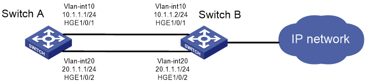
Network configuration
As shown in Figure 1, Switch A has two equal-cost routes to Switch B. Configure load sharing based on source and destination addresses on Switch A to forward packets through Switch B to the destination IP address 1.2.3.4/24.
Procedure
# On Switch A, assign HundredGigE 1/0/1 to VLAN 10, and HundredGigE 1/0/2 to VLAN 20.
<SwitchA> system-view
[SwitchA] vlan 10
[SwitchA-vlan10] port hundredgige 1/0/1
[SwitchA-vlan10] quit
[SwitchA] vlan 20
[SwitchA-vlan20] port hundredgige 1/0/2
[SwitchA-vlan20] quit
# On Switch A, configure IP addresses for VLAN-interface 10 and VLAN-interface 20.
[SwitchA] interface vlan-interface 10
[SwitchA-Vlan-interface10] ip address 10.1.1.1 24
[SwitchA-Vlan-interface10] quit
[SwitchA] interface vlan-interface 20
[SwitchA-Vlan-interface20] ip address 20.1.1.1 24
[SwitchA-Vlan-interface20] quit
# On Switch B, assign HundredGigE 1/0/1 to VLAN 10, and HundredGigE 1/0/2 to VLAN 20.
<SwitchB> system-view
[SwitchB] vlan 10
[SwitchB-vlan10] port hundredgige 1/0/1
[SwitchB-vlan10] quit
[SwitchB] vlan 20
[SwitchB-vlan20] port hundredgige 1/0/2
[SwitchB-vlan20] quit
# On Switch B, configure IP addresses for VLAN-interface 10 and VLAN-interface 20.
[SwitchB] interface vlan-interface 10
[SwitchB-Vlan-interface10] ip address 10.1.1.2 24
[SwitchB-Vlan-interface10] quit
[SwitchB] interface vlan-interface 20
[SwitchB-Vlan-interface20] ip address 20.1.1.2 24
[SwitchB-Vlan-interface20] quit
# On Switch A, configure two static routes to the destination IP address 1.2.3.4.
<SwitchA> system-view
[SwitchA] ip route-static 1.2.3.4 24 10.1.1.2
[SwitchA] ip route-static 1.2.3.4 24 20.1.1.2
[SwitchA] quit
# On Switch A, display FIB entries matching the destination IP address 1.2.3.4.
<SwitchA> display fib 1.2.3.4
Destination count: 1 FIB entry count: 2
Flag:
U:Useable G:Gateway H:Host B:Blackhole D:Dynamic S:Static
R:Relay F:FRR
Destination/Mask Nexthop Flag OutInterface/Token Label
1.2.3.0/24 10.1.1.2 USGR Vlan10 Null
1.2.3.0/24 20.1.1.2 USGR Vlan20 Null
# On Switch A, configure per-flow load sharing based on source and destination IP addresses.
<SwitchA> system-view
[SwitchA] ip load-sharing mode per-flow dest-ip src-ip global
[SwitchA] quit
Verifying the configuration
# Verify that Switch A implements load sharing.
<SwitchA> display counters outbound interface HundredGigE
Interface Total (pkts) Broadcast (pkts) Multicast (pkts) Err (pkts)
HGE1/0/1 1045 0 0 0
HGE1/0/2 1044 0 0 0