- Table of Contents
- Related Documents
-
| Title | Size | Download |
|---|---|---|
| 01-Hardware Information and Specifications | 3.64 MB |
Contents
1 Product models and technical specifications
IE4320S rack mounting industrial switches
IE4320 DIN-rail mounting industrial switches
IE4320 TSN DIN-rail mounting industrial switches
IE4320 rack mounting industrial switches
IE4320 M12 rack mounting industrial switches
IE4320-12P-PWR-M/IE4320-12P-PWR-M-NAT
3 Removable components and compatibility matrixes
10/100/1000BASE-T Ethernet port
Removable power supply status LED
10/100/1000BASE-T autosensing Ethernet port LED
1 Product models and technical specifications
Product models
This document is applicable to the IE4320 industrial switch series. Table1-1 describes the IE4320 industrial switch models.
Table1-1 IE4320 industrial switch models
|
Subseries |
Switch model |
|
IE4320S rack mounting industrial switch series |
IE4320S-26S |
|
IE4320S-50S |
|
|
IE4320 DIN-rail mounting industrial switch series |
IE4320-6P |
|
IE4320-6P-AC |
|
|
IE4320-12P |
|
|
IE4320-12P-UPWR |
|
|
IE4320-20P |
|
|
IE4320 TSN DIN-rail mounting industrial switch series |
IE4320-10S |
|
IE4320-10S-UPWR |
|
|
IE4320 rack mounting industrial switch series |
IE4320-28F |
|
IE4320-28P |
|
|
IE4320-28P-S |
|
|
IE4320-28S |
|
|
IE4320-28S-HPWR |
|
|
IE4320-28S-PS1 |
|
|
IE4320-52P |
|
|
IE4320-52S |
|
|
IE4320 M12 rack mounting industrial switch series |
IE4320-12P-PWR-M |
|
IE4320-12P-PWR-M-NAT |
The IE4320-28P switch model includes switches with the LS-IE4320-28P and LS-IE4320-28P-K product codes. Information described for the IE4320-28P switch model applies to the switches with the LS-IE4320-28P or LS-IE4320-28P-K product code.
Technical specifications
Table1-2 Technical specifications for the IE4320S rack mounting industrial switches
|
Item |
IE4320S-26S |
IE4320S-50S |
|
Dimensions (H × W × D) |
43.6 × 440 × 360 mm (1.72 × 17.32 × 14.17 in) |
43.6 × 440 × 360 mm (1.72 × 17.32 × 14.17 in) |
|
Weight |
≤ 6.5 kg (14.33 lb) |
≤ 6.5 kg (14.33 lb) |
|
Console port |
1 × serial console port |
1 × serial console port |
|
10/100/1000BASE-T autosensing Ethernet port |
24 |
48 |
|
SFP+ port |
2 |
2 |
|
Power supply slot |
2, in the rear panel |
2, in the rear panel |
|
Input voltage |
PSR75-12A power supply: · Rated voltage range: ¡ 100 to 240 VAC @ 50 or 60 Hz ¡ 240 VDC · Max voltage range: ¡ 90 to 290 VAC @ 47 to 63 Hz ¡ 180 to 320 VDC |
|
|
Power consumption (static) |
· Single power input: 18 W · Dual power inputs: 20 W |
· Single power input: 18 W · Dual power inputs: 20 W |
|
Power consumption (fully configured) |
· Single power input: 30 W · Dual power inputs: 37 W |
· Single power input: 41 W · Dual power inputs: 43 W |
|
Melting current of power supply fuse |
3.15 A/250 V |
|
|
Operating altitude |
–60 to +5000 m (–196.85 to +16404.20 ft) The maximum acceptable temperature decreases by 0.33°C (32.59°F) for every 100 m (328.08 ft) increase in altitude from Tmax@0m. |
|
|
Operating temperature |
0°C to 50°C (32°F to 122°F) |
|
|
Operating humidity |
5% RH to 95% RH, noncondensing |
|
|
Safety compliance |
UL60950-1 EN60950-1 IEC60950-1 GB4943.1 UL62368-1 EN62368-1 IEC62368-1 |
|
Table1-3 Technical specifications for the IE4320 rack mounting industrial switches (1)
|
Item |
Non-PoE switch model |
|||
|
IE4320-28P |
IE4320-28S |
IE4320-28S-PS1 |
IE4320-28P-S |
|
|
Dimensions (H × W × D) |
43.6 × 440 × 260 mm (1.72 × 17.32 × 10.24 in) |
43.6 × 440 × 260 mm (1.72 × 17.32 × 10.24 in) |
43.6 × 440 × 260 mm (1.72 × 17.32 × 10.24 in) |
43.6 × 440 × 260 mm (1.72 × 17.32 × 10.24 in) |
|
Weight |
≤ 4 kg (8.82 lb) |
≤ 4 kg (8.82 lb) |
≤ 4 kg (8.82 lb) |
≤ 4 kg (8.82 lb) |
|
Console port |
1 |
1 |
1 |
1 |
|
USB port |
1 |
1 |
1 |
1 |
|
10/100/1000BASE-T autosensing Ethernet port |
24 (The eight highest-numbered 10/100/1000BASE-T autosensing Ethernet ports and eight their corresponding lowest-numbered SFP ports form combo interfaces.) |
24 (The eight highest-numbered 10/100/1000BASE-T autosensing Ethernet ports and their corresponding SFP ports form combo interfaces.) |
24 (The eight highest-numbered 10/100/1000BASE-T autosensing Ethernet ports and their corresponding SFP ports form combo interfaces.) |
24 |
|
SFP port |
12 |
8 |
8 |
4 |
|
SFP+ port |
N/A |
4 |
4 |
N/A |
|
Alarm input (DI) |
The system detects exceptions of the connected device based on the input voltage changes on the alarm input connection. · State: ¡ 1: +13 to +30 V ¡ 0: –30 to + 3 V · Max. input current: 8 mA |
|||
|
Alarm output (DO) |
Uses a relay for output, with a current carrying capacity of 1A @ 24 VDC The relay outputs alarms by opening or closing the contact. |
|||
|
DIP switch |
Supported. For more information, see "DIP switches." |
|||
|
Input voltage |
· Rated voltage range: 100 to 240 VAC @ 50 or 60 Hz · Max voltage range: 90 to 264 VAC @ 47 to 63 Hz |
· Rated voltage range: 100 to 240 VAC @ 50 or 60 Hz · Max voltage range: 90 to 264 VAC @ 47 to 63 Hz |
· AC input: ¡ Rated voltage range: 100 to 240 VAC @ 50 or 60 Hz ¡ Max voltage range: 90 to 264 VAC @ 47 to 63 Hz · DC input: ¡ Rated voltage range: 24 to 48 VDC ¡ Max voltage range: 24 to 48 VDC |
· Rated voltage range: 100 to 240 VAC @ 50 or 60 Hz · Max voltage range: 90 to 264 VAC @ 47 to 63 Hz |
|
Power consumption (static) |
· Single AC input: 14 W · Dual AC inputs: 15 W |
· Single AC input: 14 W · Dual AC inputs: 15 W |
· Single AC input: 13 W · Single DC input: 16 W · AC + DC inputs: 20 W |
· Single AC input: 14 W · Dual AC inputs: 15 W |
|
Power consumption (fully configured) |
· Single AC input: 28 W · Dual AC inputs: 30 W |
· Single AC input: 30 W · Dual AC inputs: 32 W |
· Single AC input: 28 W · Single DC input: 29 W · AC + DC inputs: 36 W |
· Single AC input: 28 W · Dual AC inputs: 30 W |
|
Melting current of power supply fuse |
2 A/250 V |
|||
|
Operating altitude |
–60 to +5000 m (–196.85 to +16404.20 ft) The maximum acceptable temperature decreases by 0.33°C (32.59°F) for every 100 m (328.08 ft) increase in altitude from Tmax@0m. |
|||
|
Operating temperature |
–25°C to +55°C (–13°F to +131°F) |
|||
|
Operating humidity |
5% RH to 95% RH, noncondensing |
|||
|
Ingress protection rating |
IP40 |
IP40 |
IP40 |
IP40 |
|
Pollution degree |
Degree 2. The switch is for indoor use only. |
|||
|
Safety compliance |
UL60950-1 EN60950-1 IEC60950-1 GB4943.1 UL62368-1 EN62368-1 IEC62368-1 |
|||
Table1-4 Technical specifications for the IE4320 rack mounting industrial switches (2)
|
Item |
Non-PoE switch model |
||
|
IE4320-28F |
IE4320-52P |
IE4320-52S |
|
|
Dimensions (H × W × D) |
43.6 × 440 × 320 mm (1.72 × 17.32 × 12.60 in) |
43.6 × 440 × 320 mm (1.72 × 17.32 × 12.60 in) |
43.6 × 440 × 320 mm (1.72 × 17.32 × 12.60 in) |
|
Weight |
≤ 5 kg (11.02 lb) |
≤ 5 kg (11.02 lb) |
≤ 5 kg (11.02 lb) |
|
Console port |
1 |
1 |
1 |
|
USB port |
1 |
1 |
1 |
|
10/100/1000BASE-T autosensing Ethernet port |
8 |
48 |
48 |
|
SFP port |
24 (The eight highest-numbered SFP ports and their corresponding 10/100/1000BASE-T autosensing Ethernet ports form combo interfaces.) |
4 |
N/A |
|
SFP+ port |
4 |
N/A |
4 |
|
Alarm input (DI) |
The system detects exceptions of the connected device based on the input voltage changes on the alarm input connection. · State: ¡ 1: +13 to +30 V ¡ 0: –30 to + 3 V · Max. input current: 8 mA |
||
|
Alarm output (DO) |
Uses a relay for output, with a current carrying capacity of 1A @ 24 VDC The relay outputs alarms by opening or closing the contact. |
||
|
DIP switch |
Supported. For more information, see "DIP switches." |
||
|
Input voltage |
· Rated voltage range: 100 to 240 VAC @ 50 or 60 Hz · Max voltage range: 90 to 264 VAC @ 47 to 63 Hz |
||
|
Power consumption (static) |
· Single AC input: 16 W · Dual AC inputs: 17 W |
· Single AC input: 20 W · Dual AC inputs: 21 W |
· Single AC input: 20 W · Dual AC inputs: 21 W |
|
Power consumption (fully configured) |
· Single AC input: 44 W · Dual AC inputs: 46 W |
· Single AC input: 41 W · Dual AC inputs: 42 W |
· Single AC input: 43 W · Dual AC inputs: 44 W |
|
Melting current of power supply fuse |
10 A/250 V |
||
|
Operating altitude |
–60 to +5000 m (–196.85 to +16404.20 ft) The maximum acceptable temperature decreases by 0.33°C (32.59°F) for every 100 m (328.08 ft) increase in altitude from Tmax@0m. |
||
|
Operating temperature |
–25°C to +55°C (–13°F to +131°F) |
||
|
Operating humidity |
5% RH to 95% RH, noncondensing |
||
|
Ingress protection rating |
IP40 |
||
|
Pollution degree |
Degree 2. The switch is for indoor use only. |
||
|
Safety compliance |
UL60950-1 EN60950-1 IEC60950-1 GB4943.1 UL62368-1 EN62368-1 IEC62368-1 |
||
Table1-5 Technical specifications for the IE4320 rack mounting industrial switches (3)
|
Item |
PoE switch model |
|
IE4320-28S-HPWR |
|
|
Dimensions (H × W × D) |
43.6 × 440 × 260 mm (1.72 × 17.32 × 10.24 in) |
|
Weight |
≤ 4 kg (8.82 lb) |
|
Console port |
1 |
|
USB port |
1 |
|
10/100/1000BASE-T autosensing Ethernet port |
24 (The 8 lowest-numbered ports support PoE++ power supply and the 16 highest-numbered ports support PoE+ power supply.) |
|
SFP+ port |
4 |
|
Alarm input (DI) |
The system detects exceptions of the connected device based on the input voltage changes on the alarm input connection. · State: ¡ 1: +13 to +30 V ¡ 0: –30 to + 3 V · Max. input current: 8 mA |
|
Alarm output (DO) |
Uses a relay for output, with a current carrying capacity of 1A @ 24 VDC The relay outputs alarms by opening or closing the contact. |
|
DIP switch |
Supported. For more information, see "DIP switches." |
|
Input voltage |
· Rated voltage range: 53 to 57 VDC · Max voltage range: 53 to 57 VDC |
|
Max PoE power per port |
· Ports 1 to 8: 60 W · Ports 9 to 24: 30 W |
|
Total PoE power |
· Single DC input: 160 W · Dual DC inputs: 360 W |
|
Power consumption (static) |
· Single DC input: 17 W · Dual DC inputs: 19 W |
|
Power consumption (fully configured, including PoE power consumption) |
· Single DC input: 198 W · Dual DC inputs: 415 W |
|
Melting current of power supply fuse |
10 A/250 V |
|
Operating altitude |
–60 to +5000 m (–196.85 to +16404.20 ft) The maximum acceptable temperature decreases by 0.33°C (32.59°F) for every 100 m (328.08 ft) increase in altitude from Tmax@0m. |
|
Operating temperature |
–25°C to +55°C (–13°F to +131°F) |
|
Operating humidity |
5% RH to 95% RH, noncondensing |
|
Ingress protection rating |
IP40 |
|
Pollution degree |
Degree 2. The switch is for indoor use only. |
|
Safety compliance |
UL60950-1 EN60950-1 IEC60950-1 GB4943.1 UL62368-1 EN62368-1 IEC62368-1 |
Table1-6 Technical specifications for the IE4320 DIN-rail mounting industrial switches
|
Item |
IE4320-6P-AC |
IE4320-6P |
IE4320-12P |
IE4320-20P |
IE4320-12P-UPWR |
|
Dimensions (H × W × D) |
150 × 44 × 130 mm (5.91 × 1.73 × 5.12 in) |
150 × 44 × 130 mm (5.91 × 1.73 × 5.12 in) |
150 × 44 × 130 mm (5.91 × 1.73 × 5.12 in) |
150 × 84 × 130 mm (5.91 × 3.31 × 5.12 in) |
150 × 44 × 130 mm (5.91 × 1.73 × 5.12 in) |
|
Weight |
≤ 1 kg (2.20 lb) |
≤ 1 kg (2.20 lb) |
≤ 1 kg (2.20 lb) |
≤ 1.6 kg (3.53 lb) |
≤ 1 kg (2.20 lb) |
|
Console port |
1 |
1 |
1 |
1 |
1 |
|
10/100/1000BASE-T autosensing Ethernet port |
4 |
4 |
8 |
16 |
8 (support PoE power supply) |
|
SFP port |
2 |
2 |
4 |
4 |
4 |
|
Alarm input (DI) |
The system detects exceptions of the connected device based on the input voltage changes on the alarm input connection. · State: ¡ 1: +13 to +30 V ¡ 0: –30 to + 3 V Max. input current: 8 mA |
||||
|
Alarm output (DO) |
Uses a relay for output, with a current carrying capacity of 1A @ 24 VDC The relay outputs alarms by opening or closing the contact. |
||||
|
DIP switch |
Supported. For more information, see "DIP switches." |
||||
|
Input voltage |
· Rated voltage range: 100 to 240 VAC @ 50 or 60 Hz · Max voltage range: 85 to 264 VAC @ 45 to 65 Hz |
· Rated voltage range: 24 to 48 VDC · Max voltage range: 24 to 48 VDC |
· Rated voltage range: 24 to 48 VDC · Max voltage range: 24 to 48 VDC |
· Rated voltage range: 24 to 48 VDC · Max voltage range: 24 to 48 VDC |
· Rated voltage range: 53 to 57 VDC · Max voltage range: 53 to 57 VDC |
|
Max PoE power per port |
N/A |
N/A |
N/A |
N/A |
Ports 1 to 8: 60 W |
|
Total PoE power |
N/A |
N/A |
N/A |
N/A |
· Single DC input: 160 W · Dual DC inputs: 360 W |
|
Power consumption (static) |
7 W |
8 W |
8 W |
9 W |
· Single DC input: 13 W · Dual DC inputs: 15 W |
|
Power consumption (fully configured) |
10 W |
11 W |
17 W |
19 W |
· Single DC input: 205 W · Dual DC inputs: 420 W |
|
Melting current of power supply fuse |
3.15 A/250 V |
||||
|
Operating altitude |
–60 to +5000 m (–196.85 to +16404.20 ft) The maximum acceptable temperature decreases by 0.33°C (32.59°F) for every 100 m (328.08 ft) increase in altitude from Tmax@0m. |
||||
|
Operating temperature |
–25°C to +55°C (–13°F to +131°F) |
||||
|
Operating humidity |
5% RH to 95% RH, noncondensing |
||||
|
Ingress protection rating |
IP41 |
IP41 |
IP41 |
IP41 |
IP40 |
|
Pollution degree |
Degree 2. The switch is for indoor use only. |
||||
|
Safety compliance |
UL60950-1 EN60950-1 IEC60950-1 GB4943.1 UL62368-1 EN62368-1 IEC62368-1 |
||||
Table1-7 Technical specifications for the IE4320 TSN DIN-rail mounting industrial switches
|
Item |
IE4320-10S |
IE4320-10S-UPWR |
|
Dimensions (H × W × D) |
150 × 44 × 130 mm (5.91 × 1.73 × 5.12 in) |
150 × 44 × 130 mm (5.91 × 1.73 × 5.12 in) |
|
Weight |
≤ 1 kg (2.20 lb) |
≤ 1 kg (2.20 lb) |
|
Console port |
1 |
1 |
|
10/100/1000BASE-T autosensing Ethernet port |
8 |
8 (support PoE power supply) |
|
SFP+ port |
2 |
2 |
|
Alarm input (DI) |
The system detects exceptions of the connected device based on the input voltage changes on the alarm input connection. · State: ¡ 1: +13 to +30 V ¡ 0: –30 to + 3 V · Max. input current: 8 mA |
|
|
Alarm output (DO) |
Uses a relay for output, with a current carrying capacity of 1A @ 24 VDC The relay outputs alarms by opening or closing the contact. |
|
|
DIP switch |
Supported. For more information, see "DIP switches." |
|
|
Input voltage |
· Rated voltage range: 24 to 48 VDC · Max voltage range: 24 to 48 VDC |
· Rated voltage range: 53 to 57 VDC · Max voltage range: 53 to 57 VDC |
|
Max PoE power per port |
N/A |
Ports 1 to 8: 60 W |
|
Total PoE power |
N/A |
· Single DC input: 160 W · Dual DC inputs: 360 W |
|
Power consumption (static) |
· Single DC input: 10 W · Dual DC inputs: 11 W |
· Single DC input: 11 W · Dual DC inputs: 12 W |
|
Power consumption (fully configured, including PoE power consumption) |
· Single DC input: 15 W · Dual DC inputs: 16 W |
· Single DC input: 200 W · Dual DC inputs: 400 W |
|
Melting current of power supply fuse |
3.15 A/250 V |
|
|
Operating altitude |
–60 to +5000 m (–196.85 to +16404.20 ft) The maximum acceptable temperature decreases by 0.33°C (32.59°F) for every 100 m (328.08 ft) increase in altitude from Tmax@0m. |
|
|
Operating temperature |
–25°C to +60°C (–13°F to +140°F) |
|
|
Operating humidity |
5% RH to 95% RH, noncondensing |
|
|
Ingress protection rating |
IP40 |
|
|
Pollution degree |
Degree 2. The switch is for indoor use only. |
|
|
Safety compliance |
UL60950-1 EN60950-1 IEC60950-1 GB4943.1 UL62368-1 EN62368-1 IEC62368-1 |
|
Table1-8 Technical specifications for IE4320 M12 rack mounting industrial switches
|
Item |
IE4320-12P-PWR-M/IE4320-12P-PWR-M-NAT |
|
Dimensions (H × W × D) |
43.6 × 440 × 200 mm (1.72 × 17.32 × 7.87 in) |
|
Weight |
≤ 4.5 kg (9.92 lb) |
|
Console port |
1 |
|
10/100/1000BASE-T autosensing Ethernet port |
12 (The eight lowest-numbered ports support PoE power supply.) |
|
Alarm input (DI) |
The system detects exceptions of the connected device based on the input voltage changes on the alarm input connection. · State: ¡ 1: +13 to +30 V ¡ 0: –30 to + 3 V · Max. input current: 8 mA |
|
Alarm output (DO) |
Uses a relay for output, with a current carrying capacity of 1A @ 24 VDC The relay outputs alarms by opening or closing the contact. |
|
Input voltage |
· Rated voltage: 110 VDC · Max voltage range: 66 to 160 VDC |
|
Max PoE power per port |
Ports 1 to 8: 30 W |
|
Total PoE power |
125 W |
|
Power consumption (static) |
12 W |
|
Power consumption (fully configured, including PoE power consumption) |
165 W |
|
Melting current of power supply fuse |
10 A/250 V |
|
Operating altitude |
–60 to +5000 m (–196.85 to +16404.20 ft) The maximum acceptable temperature decreases by 0.33°C (32.59°F) for every 100 m (328.08 ft) increase in altitude from Tmax@0m. |
|
Operating temperature |
–25°C to +55°C (–13°F to +131°F) |
|
Operating humidity |
5% RH to 95% RH, noncondensing |
|
Ingress protection rating |
IP54 |
|
Pollution degree |
Degree 2. The switch is for indoor use only. |
|
Safety compliance |
UL60950-1 EN60950-1 IEC60950-1 GB4943.1 UL62368-1 EN62368-1 IEC62368-1 |
DIP switches
Some switch models provide DIP switches to enable or disable corresponding features.
Table1-9 DIP switch descriptions
|
Switch model |
DIP switch 1 |
DIP switch 2 |
DIP switch 3 |
DIP switch 4 |
|
IE4320-10S IE4320-10S-UPWR |
Enables or disables flow control on all ports |
Enables or disables broadcast suppression on all ports |
Reserved |
Enables or disables RRPP on ports 9 and 10 |
|
IE4320-28F IE4320-28P IE4320-28P-S IE4320-28S IE4320-28S-PS1 IE4320-28S-HPWR |
Enables or disables link aggregation on ports 25 and 26 |
Enables or disables RRPP on ports 27 and 28 |
||
|
IE4320-52P IE4320-52S |
Enables or disables link aggregation on ports 49 and 50 |
Enables or disables RRPP on ports 51 and 52 |
||
|
IE4320-6P IE4320-6P-AC |
Reserved |
Enables or disables RRPP on ports 5 and 6 |
||
|
IE4320-12P IE4320-12P-UPWR |
Enables or disables link aggregation on ports 9 and 10 |
Enables or disables RRPP on ports 11 and 12 |
||
|
IE4320-20P |
Enables or disables link aggregation on ports 17 and 18 |
Enables or disables RRPP on ports 19 and 20 |
When DIP switch 1 is on, flow control is enabled on all ports. When DIP switch 1 is off, the status of the flow control feature depends on the configuration. For more information about flow control, see Ethernet interface configuration in the configuration guides for the switch.
When DIP switch 2 is on, broadcast suppression is enabled on all ports. When DIP switch 2 is off, the status of the broadcast suppression feature depends on the configuration. For more information about broadcast suppression, see Ethernet interface configuration in the configuration guides for the switch.
When DIP switch 3 is on, the system creates Layer 2 aggregation group 1 and adds the two uplink Ethernet ports to the group. When DIP switch 3 is off, the status of the link aggregation feature depends on the configuration. For more information about Layer 2 link aggregation, see Ethernet link aggregation configuration in the configuration guides for the switch.
When DIP switch 4 is on, RRPP is enabled. When DIP switch 4 is off, the status of the RRPP feature depends on the configuration. For more information, see RRPP configuration in the configuration guides for the switch.
2 Chassis views
IE4320S rack mounting industrial switches
IE4320S-26S
Figure2-1 Front panel
|
(1) 10/100/1000BASE-T autosensing Ethernet port |
(2) 10/100/1000BASE-T autosensing Ethernet port LED |
|
(3) Power supply 1 status LED (PWR1) |
(4) Power supply 2 status LED (PWR2) |
|
(5) System status LED (SYS) |
(6) Console port |
|
(7) SFP+ port LED |
(8) SFP+ port |
|
(1) Grounding screw |
(2) Removable power supply 1 |
|
(3) Removable power supply 2 |
|
The IE4320S-26S switch comes with power supply slot 1 empty and power supply slot 2 installed with a filler panel. You can install one or two power supplies for the switch as needed. In Figure2-2, two PSR75-12A AC power supplies are installed.
IE4320S-50S
Figure2-3 Front panel
|
(1) 10/100/1000BASE-T autosensing Ethernet port |
(2) 10/100/1000BASE-T autosensing Ethernet port LED |
|
(3) Power supply 1 status LED (PWR1) |
(4) Power supply 2 status LED (PWR2) |
|
(5) System status LED (SYS) |
(6) Console port |
|
(7) SFP+ port LED |
(8) SFP+ port |

|
(1) Grounding screw |
(2) Removable power supply 1 |
|
(3) Removable power supply 2 |
|
The IE4320S-50S switch comes with power supply slot 1 empty and power supply slot 2 installed with a filler panel. You can install one or two power supplies for the switch as needed. In Figure2-4, two PSR75-12A AC power supplies are installed.
IE4320 DIN-rail mounting industrial switches
IE4320-6P
Figure2-5 Front panel
|
(1) Power supply status LED (PWR2) |
(2) Diag LED (Diag) |
|
(3) 10/100/1000BASE-T autosensing Ethernet port LED |
(4) 10/100/1000BASE-T autosensing Ethernet port |
|
(5) SFP port |
(6) SFP port LED |
|
(7) Alarm LED (Alarm) |
(8) Power supply status LED (PWR1) |
Figure2-6 Top panel
|
(1) Alarm input connection (DI) |
(2) Alarm output connection (DO) |
|
(3) DC power receptacle 2 (PWR2) |
(4) DC power receptacle 1 (PWR1) |
|
(5) DIP switch |
(6) Console port |
|
(7) Grounding screw |
|
IE4320-6P-AC
Figure2-7 Front panel
|
(1) Diag LED (Diag) |
(2) 10/100/1000BASE-T autosensing Ethernet port LED |
|
(3) 10/100/1000BASE-T autosensing Ethernet port |
(4) SFP port |
|
(5) SFP port LED |
(6) Alarm LED (Alarm) |
|
(7) Power supply status LED (PWR) |
|
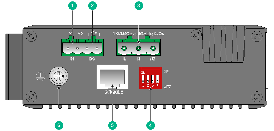
Figure2-8 Top panel
|
(1) Alarm input connection (DI) |
(2) Alarm output connection (DO) |
|
(3) AC power receptacle |
(4) DIP switch |
|
(5) Console port |
(6) Grounding screw |
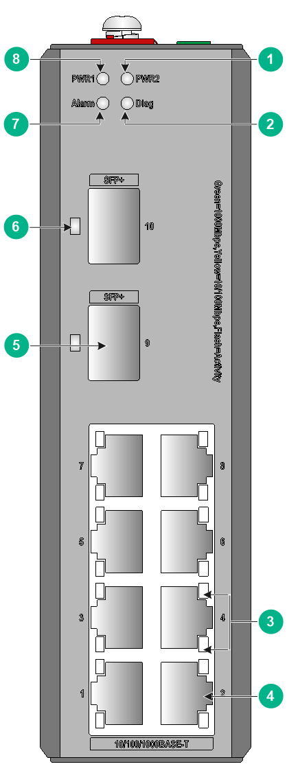
IE4320-12P
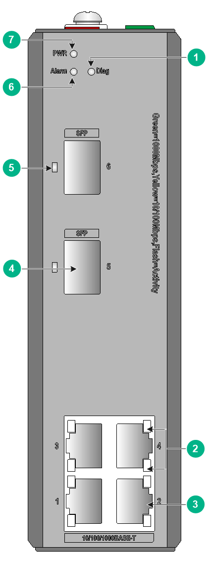
Figure2-9 Front panel
|
(1) Power supply status LED (PWR2) |
(2) Diag LED (Diag) |
|
(3) 10/100/1000BASE-T autosensing Ethernet port LED |
(4) 10/100/1000BASE-T autosensing Ethernet port |
|
(5) SFP port |
(6) SFP port LED |
|
(7) Alarm LED (Alarm) |
(8) Power supply status LED (PWR1) |
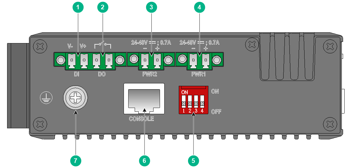
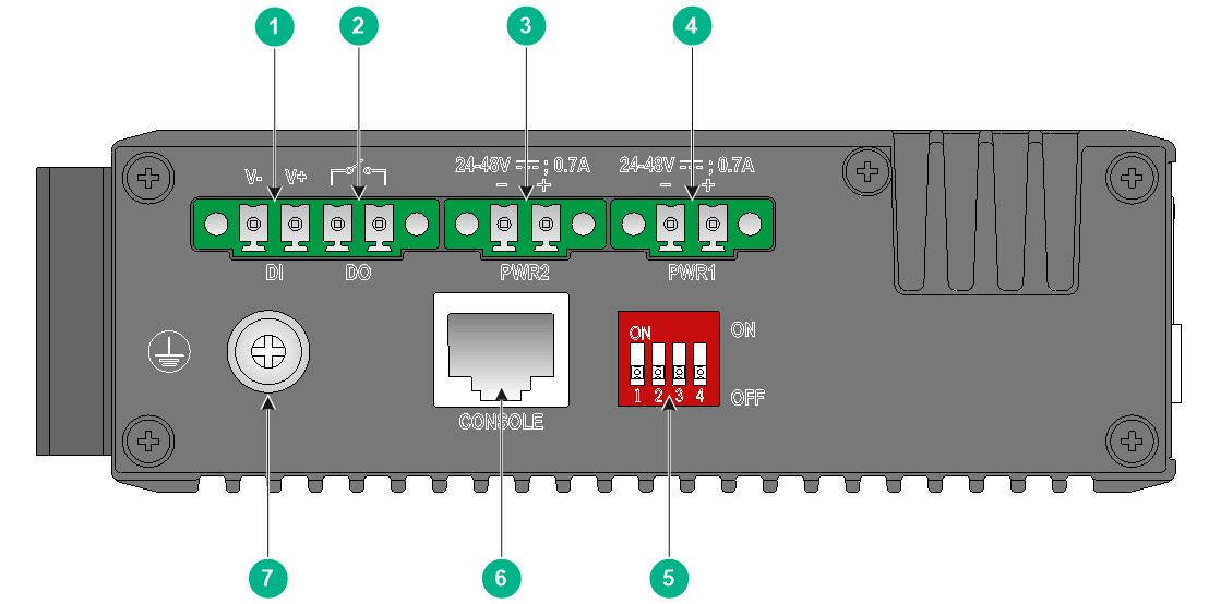
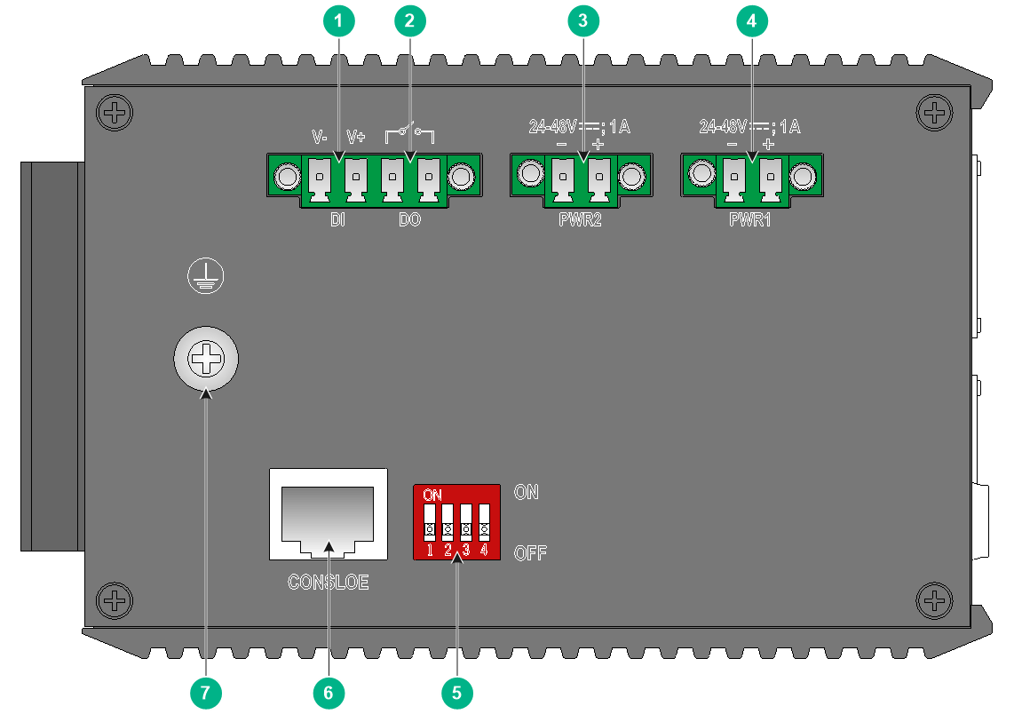
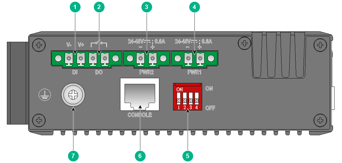
Figure2-10 Top panel
|
(1) Alarm input connection (DI) |
(2) Alarm output connection (DO) |
|
(3) DC power receptacle 2 (PWR2) |
(4) DC power receptacle 1 (PWR1) |
|
(5) DIP switch |
(6) Console port |
|
(7) Grounding screw |
|
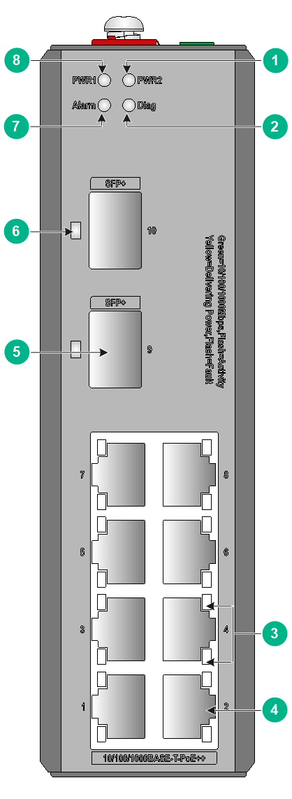
IE4320-12P-UPWR
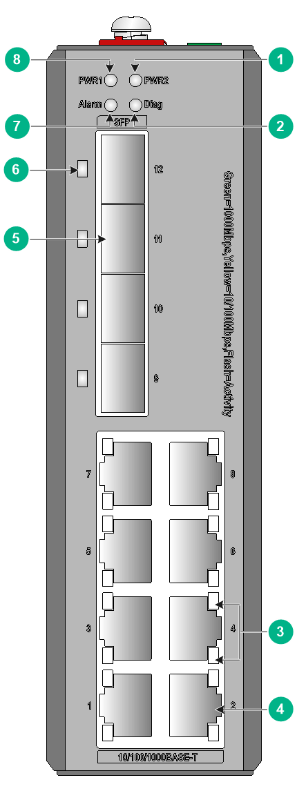
Figure2-11 Front panel

|
(1) Power supply status LED (PWR2) |
(2) Diag LED (Diag) |
|
(3) 10/100/1000BASE-T autosensing Ethernet port LED |
(4) 10/100/1000BASE-T autosensing Ethernet port |
|
(5) SFP port |
(6) SFP port LED |
|
(7) Alarm LED (Alarm) |
(8) Power supply status LED (PWR1) |
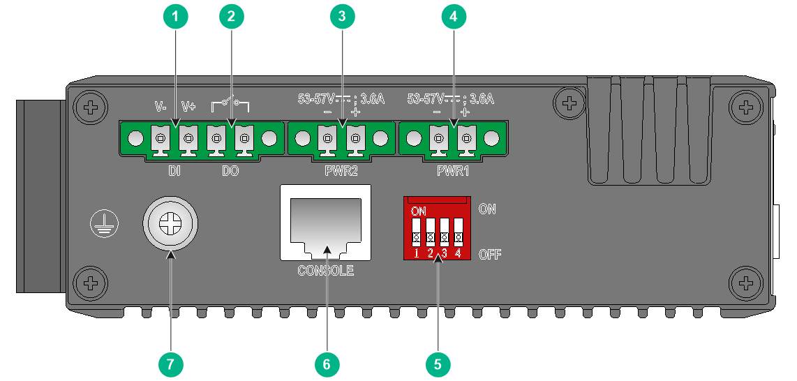
Figure2-12 Top panel
|
(1) Alarm input connection (DI) |
(2) Alarm output connection (DO) |
|
(3) DC power receptacle 2 (PWR2) |
(4) DC power receptacle 1 (PWR1) |
|
(5) DIP switch |
(6) Console port |
|
(7) Grounding screw |
|
IE4320-20P
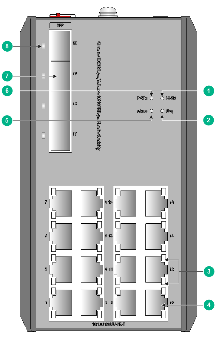
Figure2-13 Front panel
|
(1) Power supply status LED (PWR2) |
(2) Diag LED (Diag) |
|
(3) 10/100/1000BASE-T autosensing Ethernet port LED |
(4) 10/100/1000BASE-T autosensing Ethernet port |
|
(5) Alarm LED (Alarm) |
(6) Power supply status LED (PWR1) |
|
(7) SFP port |
(8) SFP port LED |
Figure2-14 Top panel
|
(1) Alarm input connection (DI) |
(2) Alarm output connection (DO) |
|
(3) DC power receptacle 2 (PWR2) |
(4) DC power receptacle 1 (PWR1) |
|
(5) DIP switch |
(6) Console port |
|
(7) Grounding screw |
|
IE4320 TSN DIN-rail mounting industrial switches
IE4320-10S
Figure2-15 Front panel
|
(1) Power supply status LED (PWR2) |
(2) Diag LED (Diag) |
|
(3) 10/100/1000BASE-T autosensing Ethernet port LED |
(4) 10/100/1000BASE-T autosensing Ethernet port |
|
(5) SFP+ port |
(6) SFP+ port LED |
|
(7) Alarm LED (Alarm) |
(8) Power supply status LED (PWR1) |
Figure2-16 Top panel
|
(1) Alarm input connection (DI) |
(2) Alarm output connection (DO) |
|
(3) DC power receptacle 2 (PWR2) |
(4) DC power receptacle 1 (PWR1) |
|
(5) DIP switch |
(6) Console port |
|
(7) Grounding screw |
|
IE4320-10S-UPWR
Figure2-17 Front panel
|
(1) Power supply status LED (PWR2) |
(2) Diag LED (Diag) |
|
(3) 10/100/1000BASE-T autosensing Ethernet port LED |
(4) 10/100/1000BASE-T autosensing Ethernet port |
|
(5) SFP+ port |
(6) SFP+ port LED |
|
(7) Alarm LED (Alarm) |
(8) Power supply status LED (PWR1) |
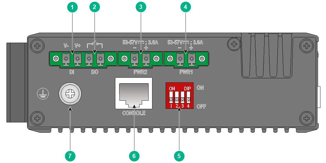
Figure2-18 Top panel
|
(1) Alarm input connection (DI) |
(2) Alarm output connection (DO) |
|
(3) DC power receptacle 2 (PWR2) |
(4) DC power receptacle 1 (PWR1) |
|
(5) DIP switch |
(6) Console port |
|
(7) Grounding screw |
|
IE4320 rack mounting industrial switches
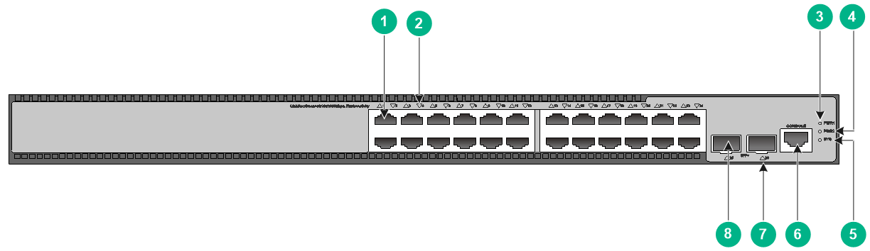
IE4320-28P
Figure2-19 Front panel
|
(1) 10/100/1000BASE-T autosensing Ethernet port |
(2) 10/100/1000BASE-T autosensing Ethernet port LED |
|
(3) Console port |
(4) USB port |
|
(5) DIP switch |
(6) Diag LED |
|
(7) Alarm LED |
(8) Power supply status LED (PWR2) |
|
(9) Power supply status LED (PWR1) |
(10) SFP port LED |
|
(11) SFP port |
|
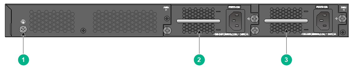
Figure2-20 Rear panel

|
(1) Alarm output connection (DO) |
(2) Alarm input connection (DI) |
|
(3) AC power receptacle 1 |
(4) AC power receptacle 2 |
|
(5) Grounding screw |
|
The IE4320-28P switch has two fixed AC power receptacles on the rear panel. One AC power receptacle can meet the power requirement of the switch. You can use both of the AC power receptacles for redundancy.
IE4320-28P-S
Figure2-21 Front panel
|
(1) 10/100/1000BASE-T autosensing Ethernet port |
(2) 10/100/1000BASE-T autosensing Ethernet port LED |
|
(3) Console port |
(4) USB port |
|
(5) DIP switch |
(6) Diag LED |
|
(7) Alarm LED |
(8) Power supply status LED (PWR2) |
|
(9) Power supply status LED (PWR1) |
(10) SFP port |
|
(11) SFP port LED |
|
Figure2-22 Rear panel

|
(1) Alarm output connection (DO) |
(2) Alarm input connection (DI) |
|
(3) AC power receptacle 1 |
(4) AC power receptacle 2 |
|
(5) Grounding screw |
|
The IE4320-28P-S switch has two fixed AC power receptacles on the rear panel. One AC power receptacle can meet the power requirement of the switch. You can use both of the AC power receptacles for redundancy.
IE4320-28S
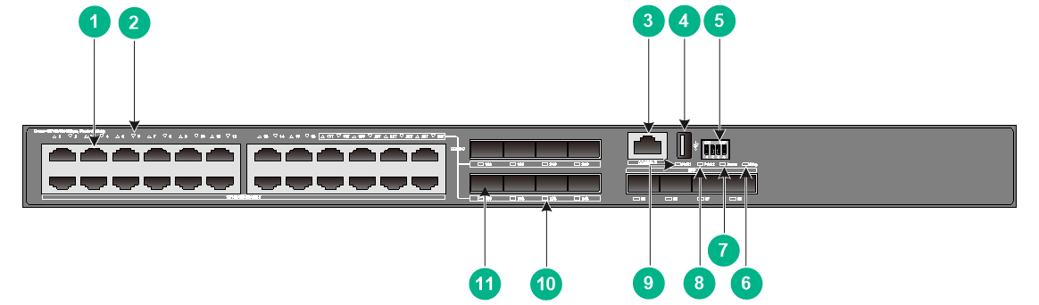
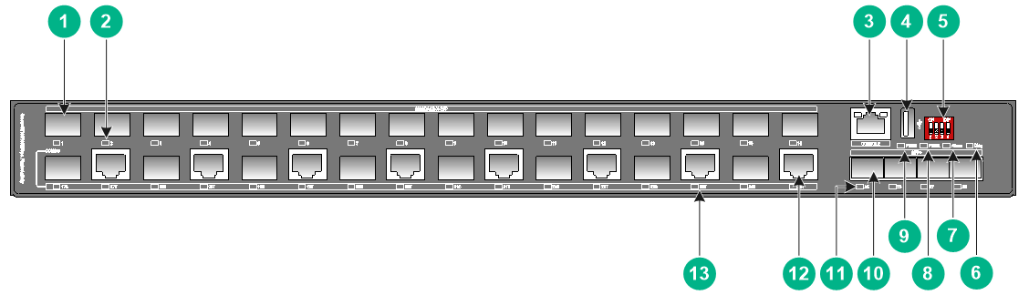
Figure2-23 Front panel
|
(1) 10/100/1000BASE-T autosensing Ethernet port |
(2) 10/100/1000BASE-T autosensing Ethernet port LED |
|
(3) Console port |
(4) USB port |
|
(5) DIP switch |
(6) Diag LED |
|
(7) Alarm LED |
(8) Power supply status LED (PWR2) |
|
(9) SFP+ port |
(10) Power supply status LED (PWR1) |
|
(11) SFP+ port LED |
(12) SFP port LED |
|
(13) SFP port |
|
Figure2-24 Rear panel
|
(1) Alarm output connection (DO) |
(2) Alarm input connection (DI) |
|
(3) AC power receptacle 1 |
(4) AC power receptacle 2 |
|
(5) Grounding screw |
|
The IE4320-28S switch has two fixed AC power receptacles on the rear panel. One AC power receptacle can meet the power requirement of the switch. You can use both of the AC power receptacles for redundancy.
IE4320-28F
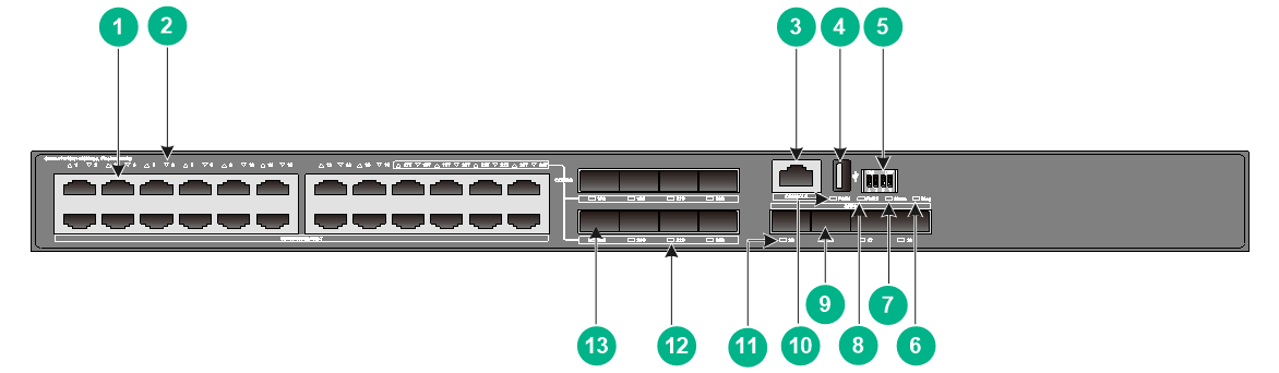
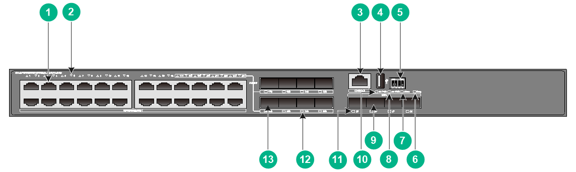
Figure2-25 Front panel
|
(1) SFP port |
(2) SFP port LED |
|
(3) Console port |
(4) USB port |
|
(5) DIP switch |
(6) Diag LED |
|
(7) Alarm LED |
(8) Power supply status LED (PWR2) |
|
(9) Power supply status LED (PWR1) |
(10) SFP+ port |
|
(11) SFP+ port LED |
(12) 10/100/1000BASE-T autosensing Ethernet port |
|
(13) 10/100/1000BASE-T autosensing Ethernet port LED |
|
Figure2-26 Rear panel

|
(1) Alarm output connection (DO) |
(2) Alarm input connection (DI) |
|
(3) AC power receptacle 1 |
(4) AC power receptacle 2 |
|
(5) Grounding screw |
|
The IE4320-28F switch has two fixed AC power receptacles on the rear panel. One AC power receptacle can meet the power requirement of the switch. You can use both of the AC power receptacles for redundancy.
IE4320-28S-HPWR
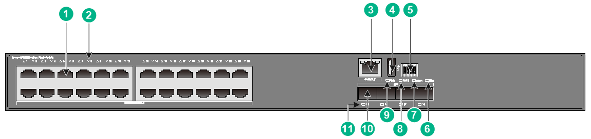
Figure2-27 Front panel

|
(1) 10/100/1000BASE-T autosensing Ethernet port |
(2) 10/100/1000BASE-T autosensing Ethernet port LED |
|
(3) Console port |
(4) USB port |
|
(5) DIP switch |
(6) Diag LED |
|
(7) Alarm LED |
(8) Power supply status LED (PWR2) |
|
(9) SFP+ port |
(10) Power supply status LED (PWR1) |
|
(11) SFP+ port LED |
|
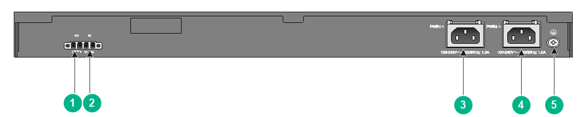
Figure2-28 Rear panel
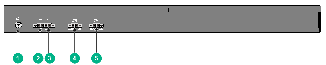
|
(1) Grounding screw |
(2) Alarm output connection (DO) |
|
(3) Alarm input connection (DI) |
(4) DC power receptacle 1 |
|
(5) DC power receptacle 2 |
|
The IE4320-28S-HPWR switch supports dual DC power feeds. You can use two H3C DG-240-55XX industrial power supplies connected in parallel to achieve load sharing for high power requirements. For more information, see Table1-5.
IE4320-28S-PS1
Figure2-29 Front panel
|
(1) 10/100/1000BASE-T autosensing Ethernet port |
(2) 10/100/1000BASE-T autosensing Ethernet port LED |
|
(3) Console port |
(4) USB port |
|
(5) DIP switch |
(6) Diag LED |
|
(7) Alarm LED |
(8) AC power supply status LED (AC PWR) |
|
(9) SFP+ port |
(10) DC power supply status LED (DC PWR) |
|
(11) SFP+ port LED |
(12) SFP port LED |
|
(13) SFP port |
|
Figure2-30 Rear panel
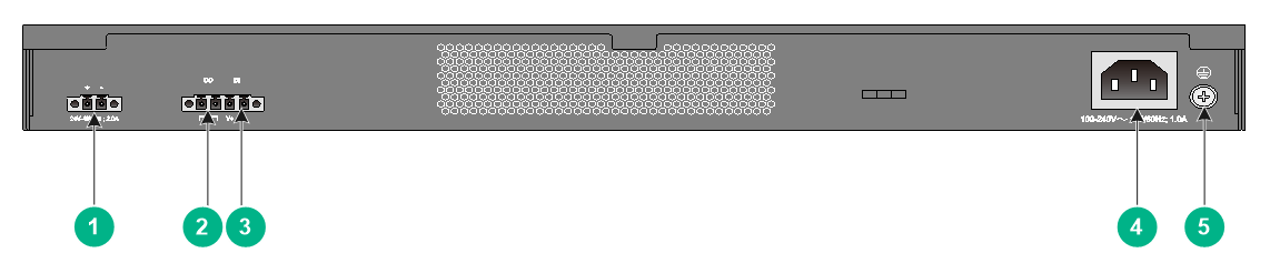
|
(1) DC power receptacle |
(2) Alarm output connection (DO) |
|
(3) Alarm input connection (DI) |
(4) AC power receptacle |
|
(5) Grounding screw |
|
The IE4320-28S-PS1 switch has one fixed AC power receptacle and one fixed DC power receptacle on the rear panel. One power receptacle can meet the power requirement of the switch. You can use both of the power receptacles for redundancy.
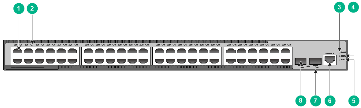
IE4320-52P
Figure2-31 Front panel
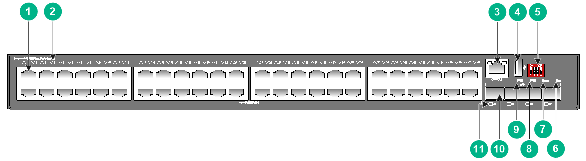
|
(1) 10/100/1000BASE-T autosensing Ethernet port |
(2) 10/100/1000BASE-T autosensing Ethernet port LED |
|
(3) Console port |
(4) USB port |
|
(5) DIP switch |
(6) Diag LED |
|
(7) Alarm LED |
(8) Power supply status LED (PWR2) |
|
(9) Power supply status LED (PWR1) |
(10) SFP port |
|
(11) SFP port LED |
|
Figure2-32 Rear panel
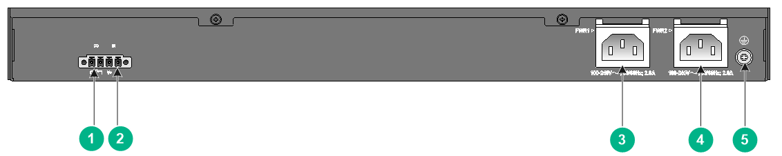
|
(1) Alarm output connection (DO) |
(2) Alarm input connection (DI) |
|
(3) AC power receptacle 1 |
(4) AC power receptacle 2 |
|
(5) Grounding screw |
|
The IE4320-52P switch has two fixed AC power receptacles on the rear panel. One AC power receptacle can meet the power requirement of the switch. You can use both of the AC power receptacles for redundancy.
IE4320-52S
Figure2-33 Front panel
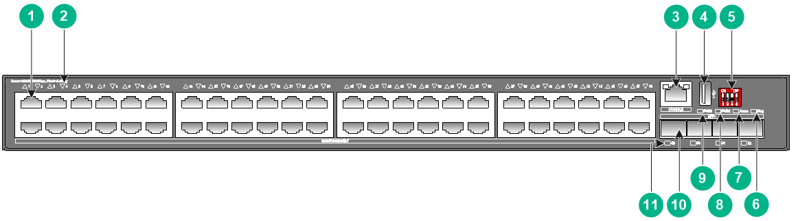
|
(1) 10/100/1000BASE-T autosensing Ethernet port |
(2) 10/100/1000BASE-T autosensing Ethernet port LED |
|
(3) Console port |
(4) USB port |
|
(5) DIP switch |
(6) Diag LED |
|
(7) Alarm LED |
(8) Power supply status LED (PWR2) |
|
(9) Power supply status LED (PWR1) |
(10) SFP+ port |
|
(11) SFP+ port LED |
|
Figure2-34 Rear panel

|
(1) Alarm output connection (DO) |
(2) Alarm input connection (DI) |
|
(3) AC power receptacle 1 |
(4) AC power receptacle 2 |
|
(5) Grounding screw |
|
The IE4320-52S switch has two fixed AC power receptacles on the rear panel. One AC power receptacle can meet the power requirement of the switch. You can use both of the AC power receptacles for redundancy.
IE4320 M12 rack mounting industrial switches
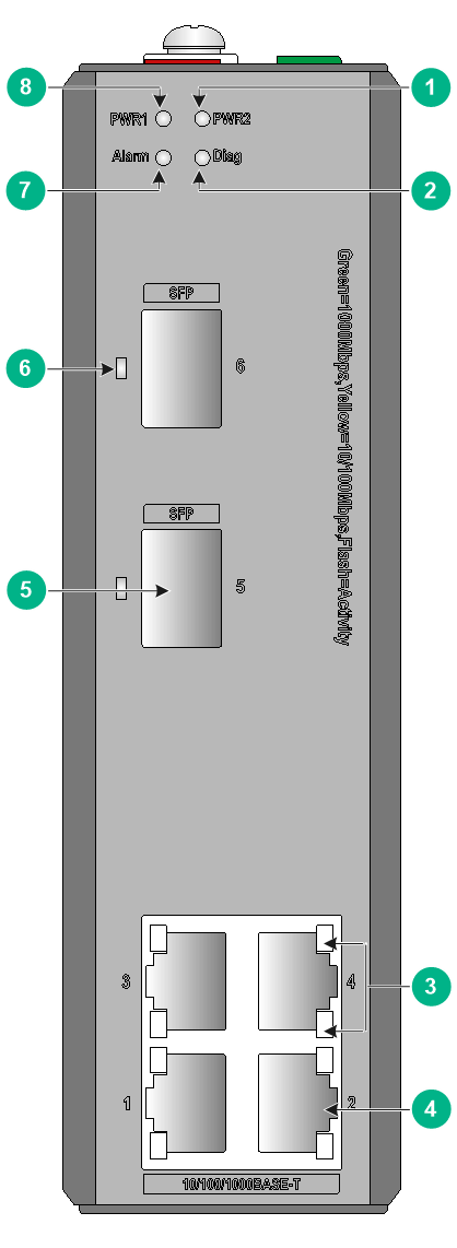
IE4320-12P-PWR-M/IE4320-12P-PWR-M-NAT
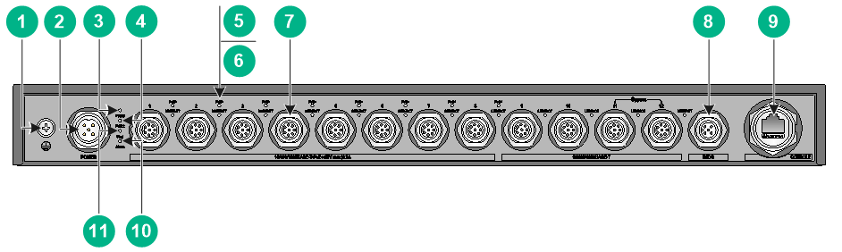
|
(1) Grounding screw |
(2) DC power receptacle |
|
(3) Power supply status LED (PWR1) |
(4) Power supply status LED (PWR2) |
|
(5) PoE status LED |
(6) 10/100/1000BASE-T autosensing Ethernet port LED |
|
(7) 10/100/1000BASE-T autosensing Ethernet port |
(8) Alarm input/output connection (DI/DO) |
|
(9) Console port |
(10) Alarm LED |
|
(11) Diag LED |
|
Figure2-36 Rear panel

3 Removable components and compatibility matrixes
Only IE4320S rack mounting industrial switches use removable power supplies. Table3-1 describes the power supplies available for the switch.
Table3-1 Compatibility matrix between switches and removable power supplies
|
Power supply model |
Item |
Specification |
Remarks |
|
PSR75-12A |
Rated input voltage range |
· AC: 100 to 240 VAC @ 50 or 60 Hz · DC: 240 VDC |
For more information about the power supply, see H3C PSR75-12A Power Module User Manual. |
|
Max input voltage range |
· AC: 90 to 290 VAC @ 47 to 63 Hz · DC: 180 to 320 VDC |
||
|
Max power |
75 W |
4 Ports and LEDs
Ports
Console port
Table4-1 Console port specifications
|
Item |
Specification |
|
Connector type |
· IE4320-12P-PWR-M/IE4320-12P-PWR-M-NAT: M12 (A-CODE) · Other switch models: RJ-45 |
|
Compliant standard |
EIA/TIA-232 |
|
Transmission baud rate |
9600 bps (default) to 115200 bps |
|
Services |
· Provides connection to an ASCII terminal. · Provides connection to the serial port of a local terminal (PC for example) running a terminal emulation program. |
|
Available switch models |
All switch models |
USB port
Table4-2 USB port specifications
|
Item |
Specification |
|
Type |
USB2.0 |
|
Compliant standard |
OHC |
|
Transmission baud rate |
480 Mbps for uploading and downloading data |
|
Services |
Used to access the file system on the flash of the switch, for example, to upload or download image files and configuration files. |
|
Available switch models |
IE4320 rack mounting industrial switches |
|
|
NOTE: USB devices from different vendors vary in compatibilities and drivers. H3C does not guarantee correct operation of USB devices from all vendors on the switch. If a USB device fails to operate on the switch, replace it with one from another vendor. |
SFP port
Table4-3 SFP port specifications
|
Item |
Specification |
|
Type |
SFP |
|
Compatible transceiver modules/cables |
· GE SFP transceiver modules or cables in Table4-5 · FE SFP transceiver modules in Table4-4 |
|
Available switch models |
· IE4320 DIN-rail mounting industrial switches · IE4320 rack mounting industrial switches except for the IE4320-28S-HPWR and IE4320-52S |
|
Restrictions and guidelines |
· Only SFP ports 17 to 24 on the IE4320-28F, IE4320-28P, IE4320-28P-S, IE4320-28S, or IE4320-28S-PS1 switch support FE SFP transceiver modules. · To use transceiver modules with a maximum transmission distance greater than or equal to 40 km (24.86 miles), make sure the ambient temperature does not exceed 40°C (104°F). |
Table4-4 FE SFP transceiver modules available for the SFP ports
|
FE SFP transceiver module |
Central wavelength (nm) |
Connector |
Fiber diameter (µm) |
Max transmission distance |
|
SFP-FE-SX-MM1310-A |
1310 |
LC |
Multi-mode, 50/125 |
2 km (1.24 miles) |
|
Multi-mode, 62.5/125 |
||||
|
SFP-FE-LX-SM1310-A |
1310 |
LC |
Single-mode, 9/125 |
15 km (9.32 miles) |
|
SFP-FE-LX-SM1310-D |
1310 |
LC |
Single-mode, 9/125 |
15 km (9.32 miles) |
|
SFP-FE-LH40-SM1310 |
1310 |
LC |
Single-mode, 9/125 |
40 km (24.86 miles) |
|
SFP-FE-LH80-SM1550 |
1550 |
LC |
Single-mode, 9/125 |
80 km (49.71 miles) |
|
SFP-FE-LX-SM1310-BIDI |
TX: 1310 RX: 1550 |
LC |
Single-mode, 9/125 |
15 km (9.32 miles) |
|
SFP-FE-LX-SM1550-BIDI |
TX: 1550 RX: 1310 |
LC |
Single-mode, 9/125 |
15 km (9.32 miles) |
|
|
IMPORTANT: The SFP-FE-LX-SM1310-BIDI and SFP-FE-LX-SM1550-BIDI transceiver modules must be used in pairs. For example, if one end uses the SFP-FE-LX-SM1310-BIDI transceiver module, the other end must use the SFP-FE-LX-SM1550-BIDI transceiver module. |
Table4-5 GE SFP transceiver modules and cables available for the SFP ports
|
GE SFP transceiver module and cable |
Central wavelength (nm) |
Connector |
Cable/Fiber type and diameter (µm) |
Modal bandwidth (MHz × km) |
Max transmission distance |
|
SFP copper transceiver modules |
|||||
|
SFP-GE-T |
N/A |
RJ-45 |
Twisted pair cable |
N/A |
100 m (328.08 ft) |
|
SFP-GE-T-D |
N/A |
RJ-45 |
Twisted pair cable |
N/A |
100 m (328.08 ft) |
|
SFP fiber transceiver modules |
|||||
|
SFP-GE-SX-MM850-A |
850 |
LC |
Multi-mode, 50/125 |
500 |
550 m (1804.46 ft) |
|
400 |
500 m (1640.42 ft) |
||||
|
Multi-mode, 62.5/125 |
200 |
275 m (902.23 ft) |
|||
|
160 |
220 m (721.78 ft) |
||||
|
SFP-GE-SX-MM850-D |
850 |
LC |
Multi-mode, 50/125 |
500 |
550 m (1804.46 ft) |
|
400 |
500 m (1640.42 ft) |
||||
|
Multi-mode, 62.5/125 |
200 |
275 m (902.23 ft) |
|||
|
160 |
220 m (721.78 ft) |
||||
|
SFP-GE-SX-MM850-S |
850 |
LC |
Multi-mode, 50/125 |
500 |
550 m (1804.46 ft) |
|
400 |
500 m (1640.42 ft) |
||||
|
Multi-mode, 62.5/125 |
200 |
275 m (902.23 ft) |
|||
|
160 |
220 m (721.78 ft) |
||||
|
SFP-GE-LX-SM1310-A |
1310 |
LC |
Single-mode, 9/125 |
N/A |
10 km (6.21 miles) |
|
Multi-mode, 50/125 |
500 or 400 |
550 m (1804.46 ft) |
|||
|
Multi-mode, 62.5/125 |
500 |
550 m (1804.46 ft) |
|||
|
SFP-GE-LX-SM1310-D |
1310 |
LC |
Single-mode, 9/125 |
N/A |
10 km (6.21 miles) |
|
SFP-GE-LX-SM1310-S |
1310 |
LC |
Single-mode, 9/125 |
N/A |
10 km (6.21 miles) |
|
SFP-GE-LX10-SM1310 |
1310 |
LC |
Single-mode, 9/125 |
N/A |
10 km (6.21 miles) |
|
SFP-GE-LH20-SM1310-I |
1310 |
LC |
Single-mode, 9/125 |
N/A |
20 km (12.43 miles) |
|
SFP-GE-LH40-SM1310 |
1310 |
LC |
Single-mode, 9/125 |
N/A |
40 km (24.86 miles) |
|
SFP-GE-LH40-SM1310-D |
1310 |
LC |
Single-mode, 9/125 |
N/A |
40 km (24.86 miles) |
|
SFP-GE-LH40-SM1310-I |
1310 |
LC |
Single-mode, 9/125 |
N/A |
40 km (24.86 miles) |
|
SFP-GE-LH40-SM1550 |
1550 |
LC |
Single-mode, 9/125 |
N/A |
40 km (24.86 miles) |
|
SFP-GE-LH80-SM1550 |
1550 |
LC |
Single-mode, 9/125 |
N/A |
80 km (49.71 miles) |
|
SFP-GE-LH80-SM1550-D |
1550 |
LC |
Single-mode, 9/125 |
N/A |
80 km (49.71 miles) |
|
SFP-GE-LH100-SM1550 |
1550 |
LC |
Single-mode, 9/125 |
N/A |
100 km (62.14 miles) |
|
SFP-GE-LX-SM1310-BIDI |
TX: 1310 RX: 1490 |
LC |
Single-mode, 9/125 |
N/A |
10 km (6.21 miles) |
|
SFP-GE-LX-SM1490-BIDI |
TX: 1490 RX: 1310 |
LC |
Single-mode, 9/125 |
N/A |
10 km (6.21 miles) |
|
SFP-GE-LH40-SM1310-BIDI |
TX: 1310 RX: 1550 |
LC |
Single-mode, 9/125 |
N/A |
40 km (24.86 miles) |
|
SFP-GE-LH40-SM1550-BIDI |
TX: 1550 RX: 1310 |
LC |
Single-mode, 9/125 |
N/A |
40 km (24.86 miles) |
|
SFP-GE-LH70-SM1490-BIDI |
TX: 1490 RX: 1550 |
LC |
Single-mode, 9/125 |
N/A |
70 km (43.50 miles) |
|
SFP-GE-LH70-SM1550-BIDI |
TX: 1550 RX: 1490 |
LC |
Single-mode, 9/125 |
N/A |
70 km (43.50 miles) |
|
SFP cable |
|||||
|
SFP-STACK-Kit |
N/A |
N/A |
SFP cable |
N/A |
1.5 m (4.92 ft) |
|
|
IMPORTANT: The SFP-GE-LX-SM1310-BIDI and SFP-GE-LX-SM1490-BIDI transceiver modules, SFP-GE-LH40-SM1310-BIDI and SFP-GE-LH40-SM1550-BIDI transceiver modules, and SFP-GE-LH70-SM1490-BIDI and SFP-GE-LH70-SM1550-BIDI transceiver modules must be used in pairs. For example, if one end uses the SFP-GE-LX-SM1310-BIDI transceiver module, the other end must use the SFP-GE-LX-SM1490-BIDI transceiver module. |
|
|
NOTE: · As a best practice, use H3C transceiver modules and network cables for the switch. · The H3C transceiver modules and network cables are subject to change over time. For the most recent list of H3C transceiver modules and cables, contact H3C Support or marketing staff. · For the specifications of H3C transceiver modules and network cables, see H3C Transceiver Modules User Guide. |
SFP+ port
Table4-6 SFP+ port specifications
|
Item |
Specification |
|
Type |
SFP+ |
|
Compatible transceiver modules/cables |
· GE SFP transceiver modules or cables in Table4-5 · 10GE SFP+ transceiver modules or cables in Table4-7, Table4-8, and Table4-9 |
|
Available switch models |
· IE4320S rack mounting industrial switches · IE4320 TSN DIN-rail mounting industrial switches · IE4320 rack mounting industrial switches except for the IE4320-28P, IE4320-28P-S, and IE4320-52P |
|
Restrictions and guidelines |
· To use transceiver modules with a maximum transmission distance greater than or equal to 40 km (24.86 miles), make sure the ambient temperature does not exceed 40°C (104°F). · The IE4320-10S and IE4320-10S-UPWR switches do not support LSTM1STK cables. |
Table4-7 10GE SFP+ transceiver modules available for the SFP+ ports
|
10GE SFP+ transceiver module |
Central wavelength (nm) |
Connector |
Fiber diameter (µm) |
Modal bandwidth (MHz × km) |
Max transmission distance |
|
SFP-XG-SX-MM850-D |
850 |
LC |
Multi-mode, 50/125 |
2000 |
300 m (984.25 ft) |
|
500 |
82 m (269.03 ft) |
||||
|
400 |
66 m (216.54 ft) |
||||
|
Multi-mode, 62.5/125 |
200 |
33 m (108.27 ft) |
|||
|
160 |
26 m (85.30 ft) |
||||
|
SFP-XG-SX-MM850-E |
850 |
LC |
Multi-mode, 50/125 |
2000 |
300 m (984.25 ft) |
|
500 |
82 m (269.03 ft) |
||||
|
400 |
66 m (216.54 ft) |
||||
|
Multi-mode, 62.5/125 |
200 |
33 m (108.27 ft) |
|||
|
160 |
26 m (85.30 ft) |
||||
|
SFP-XG-SX-MM850-S |
850 |
LC |
Multi-mode, 50/125 |
2000 |
300 m (984.25 ft) |
|
500 |
82 m (269.03 ft) |
||||
|
400 |
66 m (216.54 ft) |
||||
|
Multi-mode, 62.5/125 |
200 |
33 m (108.27 ft) |
|||
|
160 |
26 m (85.30 ft) |
||||
|
SFP-XG-LX-SM1310-D |
1310 |
LC |
Single-mode, 9/125 |
N/A |
10 km (6.21 miles) |
|
SFP-XG-LX-SM1310-E |
1310 |
LC |
Single-mode, 9/125 |
N/A |
10 km (6.21 miles) |
|
SFP-XG-LX-SM1310-S |
1310 |
LC |
Single-mode, 9/125 |
N/A |
10 km (6.21 miles) |
|
SFP-XG-LH40-SM1550 |
1550 |
LC |
Single-mode, 9/125 |
N/A |
40 km (24.86 miles) |
|
SFP-XG-LH40-SM1550-D |
1550 |
LC |
Single-mode, 9/125 |
N/A |
40 km (24.86 miles) |
|
SFP-XG-LH80-SM1550 |
1550 |
LC |
Single-mode, 9/125 |
N/A |
80 km (49.71 miles) |
|
SFP-XG-LH80-SM1550-D |
1550 |
LC |
Single-mode, 9/125 |
N/A |
80 km (49.71 miles) |
|
SFP-XG-LX-SM1270-BIDI |
TX: 1270 RX: 1330 |
LC |
Single-mode, 9/125 |
N/A |
10 km (6.21 miles) |
|
SFP-XG-LX-SM1330-BIDI |
TX: 1330 RX: 1270 |
LC |
Single-mode, 9/125 |
N/A |
10 km (6.21 miles) |
|
SFP-XG-LH40-SM1270-BIDI |
TX: 1270 RX: 1330 |
LC |
Single-mode, 9/125 |
N/A |
40 km (24.86 miles) |
|
SFP-XG-LH40-SM1330-BIDI |
TX: 1330 RX: 1270 |
LC |
Single-mode, 9/125 |
N/A |
40 km (24.86 miles) |
|
|
IMPORTANT: The SFP-XG-LX-SM1270-BIDI and SFP-XG-LX-SM1330-BIDI transceiver modules and SFP-XG-LH40-SM1270-BIDI and SFP-XG-LH40-SM1330-BIDI transceiver modules must be used in pairs. For example, if one end uses an SFP-XG-LX-SM1270-BIDI transceiver module, the other end must use an SFP-XG-LX-SM1330-BIDI transceiver module. |
Table4-8 SFP+ copper cables available for the SFP+ ports
|
SFP+ copper cable |
Cable length |
|
LSWM1STK |
0.65 m (2.13 ft) |
|
LSWM2STK |
1.2 m (3.94 ft) |
|
LSWM3STK |
3 m (9.84 ft) |
|
LSTM1STK |
5 m (16.40 ft) |
Table4-9 SFP+ fiber cables available for the SFP+ ports
|
SFP+ fiber cable |
Cable length |
|
SFP-XG-D-AOC-7M |
7 m (22.97 ft) |
|
SFP-XG-D-AOC-10M |
10 m (32.81 ft) |
|
SFP-XG-D-AOC-20M |
20 m (65.62 ft) |
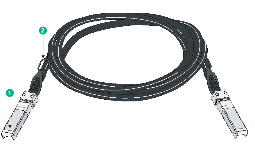
Figure4-1 SFP+ cable
|
(1) Connector |
(2) Pull latch |
|
|
NOTE: · As a best practice, use H3C transceiver modules and network cables for the switch. · The H3C transceiver modules and network cables are subject to change over time. For the most recent list of H3C transceiver modules and cables, contact H3C Support or marketing staff. · For the specifications of H3C transceiver modules and network cables, see H3C Transceiver Modules User Guide. |
10/100/1000BASE-T Ethernet port
Table4-10 10/100/1000BASE-T Ethernet port specifications
|
Item |
Specification |
|
Connector type |
· IE4320-12P-PWR-M/IE4320-12P-PWR-M-NAT: M12 (A-CODE) · Other switch models: RJ-45 |
|
Rate and duplex mode |
· 10 Mbps, half/full-duplex · 100 Mbps, half/full-duplex · 1000 Mbps, full-duplex |
|
Auto MDI/MDI-X |
Supported |
|
Transmission medium and max transmission distance |
100 m (328.08 ft) over category-5 or above twisted pair cable |
|
Compliant standard |
IEEE 802.3i, 802.3u, 802.3ab |
|
Available switch models |
All switch models. The 10/100/1000BASE-T Ethernet ports on an IE4320-12P-PWR-M or IE4320-12P-PWR-M-NAT switch use M12 (A-CODE) connectors. The 10/100/1000BASE-T Ethernet ports on the other switch models use RJ-45 connectors. |
Combo interface
Table4-11 Combo interface specifications
|
Item |
Specification |
|
Type |
Combo |
|
Available switch models |
The IE4320-28F, IE4320-28P, IE4320-28S, and IE4320-28S-PS1 switches each provide eight combo interfaces on the front panel. |
|
Restrictions and guidelines |
A combo interface contains an SFP port and a 10/100/1000BASE-T autosensing Ethernet port. Only one of these two ports can operate at a time. |
LEDs
System status LED
Only the IE4320S rack mounting industrial switches each provide a system status LED on the front panel to indicate the operating status of the switch.
Table4-12 System status LED description
|
LED mark |
Status |
Description |
|
SYS |
Steady yellow |
Boot ROM booting stage. |
|
Steady green |
Linux kernel booting stage, or the switch has started up correctly. |
|
|
Flashing green (1 Hz) |
Software image loading and decompressing stage, or software booting stage. |
|
|
Steady red |
The switch has failed power-on self test (POST) or the switch is faulty. |
|
|
Off |
The switch is powered off or has not started up correctly. |
Removable power supply status LED
Only the IE4320S rack mounting industrial switches each provide two power supply slots at the rear. For each power supply, the switch provides a power supply status LED on the front panel.
Table4-13 Description for removable power supply status LEDs
|
LED mark |
Status |
Description |
|
PWR1/PWR2 |
Steady green |
A power supply is installed in the power supply slot, and the power supply is outputting power correctly. |
|
Steady yellow |
A power supply is installed in the power supply slot, but the power supply is faulty or no power is input to the power supply. |
|
|
Off |
No power supply is installed in the power supply slot. |
Fixed power supply status LED
All IE4320 industrial switches except the IE4320S-26S and IE4320S-50S switches use fixed power supply status LEDs to indicate the power input status. Table4-14 provides the description of the fixed power supply status LEDs on the switch.
Table4-14 Description for the fixed power supply status LEDs on the switch
|
Switch model |
LED mark |
Status |
Description |
|
IE4320-28F IE4320-28P IE4320-28P-S IE4320-28S IE4320-52P IE4320-52S |
PWR1/PWR2 |
Steady green |
Normal AC power input |
|
Off |
Abnormal or no AC power input |
||
|
IE4320-6P-AC |
PWR |
Steady green |
Normal AC power input |
|
Off |
Abnormal or no AC power input |
||
|
IE4320-6P IE4320-10S IE4320-10S-UPWR IE4320-12P IE4320-12P-UPWR IE4320-12P-PWR-M IE4320-12P-PWR-M-NAT IE4320-20P IE4320-28S-HPWR |
PWR1/PWR2 |
Steady green |
Normal DC power input |
|
Off |
Abnormal or no DC power input |
||
|
IE4320-28S-PS1 |
DC PWR |
Steady green |
Normal DC power input |
|
Off |
Abnormal or no DC power input |
||
|
AC PWR |
Steady green |
Normal AC power input |
|
|
Off |
Abnormal or no AC power input |
The IE4320-12P-PWR-M switch provides a built-in power adapter. The compatible power cord contains two DC input circuits for redundancy.
Table4-15 Description for the power supply status LED on the IE4320-12P-PWR-M switch
|
LED mark |
Status |
Description |
|
PWR1/PWR2 |
PWR1: Steady green PWR2: Steady green |
Normal DC power input |
|
PWR1: Off |
Active DC power input failure has occurred or no power input. |
|
|
PWR2: Off |
Standby DC power input failure has occurred or no power input. |
PoE status LED
Only the IE4320-12P-PWR-M and IE4320-12P-PWR-M-NAT switches provide a PoE status LED to indicate the PoE power supply status.
Table4-16 PoE status LED description
|
LED mark |
Status |
Description |
|
PoE+ |
Steady yellow |
PoE is enabled on the Ethernet port. |
|
Off |
PoE is disabled on the Ethernet port. |
Alarm LED
All IE4320 industrial switches except the IE4320S-26S and IE4320S-50S switches each provide an alarm input connection and can detect changes of the digital input voltage. When the digital input voltage exceeds the acceptable range, the system uses the alarm LED to indicate the exception.
Table4-17 Alarm LED description
|
LED mark |
Status |
Description |
|
Alarm |
Steady red |
A digital input exception has been detected. |
|
Off |
No exception has been detected. |
Diag LED
All IE4320 industrial switches except the IE4320S-26S and IE4320S-50S switches each provide a Diag LED on the front panel to indicate the system operating status.
Table4-18 Diag LED description
|
LED mark |
Status |
Description |
|
Diag |
Steady red |
The switch has failed the POST, or an alarm condition such as MAC chip overtemperature has occurred. |
|
Off |
The switch has passed the POST and is operating correctly. |
10/100/1000BASE-T autosensing Ethernet port LED
Table4-19 10/100/1000BASE-T autosensing Ethernet port LED description for non-PoE switch models
|
Switch model |
LED |
Status |
Description |
|
IE4320S-26S IE4320S-50S IE4320-28P IE4320-28P-S IE4320-28S IE4320-28F IE4320-28S-PS1 IE4320-52P IE4320-52S |
Green LED |
Steady on |
A link is present on the port. |
|
Flashing |
The port is sending or receiving data. |
||
|
Off |
No link is present on the port. |
||
|
IE4320-6P IE4320-6P-AC IE4320-10S IE4320-12P IE4320-20P |
Green LED |
Steady on |
A link is present on the port and the port is operating at 1000 Mbps. |
|
Flashing |
The port is sending or receiving data at 1000 Mbps. |
||
|
Off |
No 1000 Mbps link is present on the port. |
||
|
Yellow LED |
Steady on |
A link is present on the port and the port is operating at 10/100 Mbps. |
|
|
Flashing |
The port is sending or receiving data at 10/100 Mbps. |
||
|
Off |
No 10/100 Mbps link is present on the port. |
Table4-20 10/100/1000BASE-T autosensing Ethernet port LED description for PoE switch models
|
Switch model |
LED |
Status |
Description |
|
IE4320-28S-HPWR IE4320-10S-UPWR IE4320-12P-UPWR IE4320-12P-PWR-M IE4320-12P-PWR-M-NAT |
Green LED |
Steady on |
The port is operating at 10/100/1000 Mbps. |
|
Flashing |
The port is sending or receiving data at 10/100/1000 Mbps. |
||
|
Off |
No link is present on the port or the link has failed. |
||
|
Yellow LED |
Steady on |
The port is connected to a PD and PoE power supply is normal. |
|
|
Flashing |
The port is connected to a PD but PoE power supply is abnormal. |
||
|
Off |
The port is not connected to a PD or PoE is not enabled on the port. |
SFP/SFP+ port LED
Table4-21 SFP/SFP+ port LED description
|
Status |
Description |
|
Steady green |
A link is present on the port. |
|
Flashing green |
The port is sending or receiving data. |
|
Off |
No link is present on the port. |
