- Table of Contents
- Related Documents
-
| Title | Size | Download |
|---|---|---|
| 04-Appendix C Cables | 126.26 KB |
1 Appendix C Cables
Console cable
RJ-45 to DB9 console cable
An RJ-45 to DB9 console cable is used to connect the console port on the firewall to the serial port on a configuration terminal (a PC for example):
· Connect the DB9 female connector of the cable to the 8-core serial port on the configuration terminal.
· Connect the RJ-45 connector of the cable to the console port on the firewall.
Figure1-1 RJ-45 to DB9 console cable
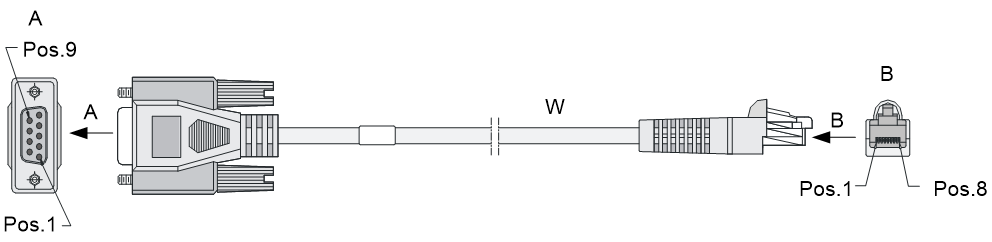
Table1-1 RJ-45 to DB9 console cable pinouts
|
RJ-45 |
Signal |
Direction |
DB-9 |
|
1 |
RTS |
← |
7 |
|
2 |
DTR |
← |
4 |
|
3 |
TXD |
← |
3 |
|
4 |
CD |
→ |
1 |
|
5 |
GND |
- |
5 |
|
6 |
RXD |
→ |
2 |
|
7 |
DSR |
→ |
6 |
|
8 |
CTS |
→ |
8 |
Micro USB console cable
A micro USB console cable is used to connect the micro USB console port on the firewall to the USB port on a configuration terminal (a PC for example):
· Connect the USB Type A connector of the cable to the USB port on the configuration terminal.
· Connect the USB Type mini-A/B connector to the micro USB console port on the firewall.
Figure1-2 Micro USB console cable
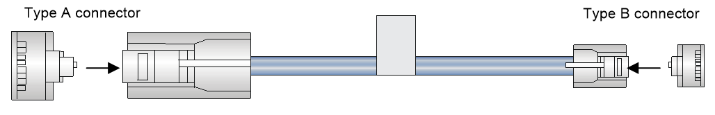
Table1-2 Micro USB console cable pinouts
|
USB Type A connector |
Signal |
USB Type mini-A/B connector |
Signal |
|
1 |
VBUS |
1 |
VBUS |
|
2 |
D- |
2 |
D- |
|
3 |
D+ |
3 |
D+ |
|
|
|
4 |
ID(NC) |
|
4 |
GND |
5 |
GND |
Ethernet twisted pair cable
Introduction
An Ethernet twisted pair cable consists of four pairs of insulated copper wires twisted together. Every wire uses a different color, and has a diameter of about 1 mm (0.04 in). A pair of twisted copper cables can cancel the electromagnetic radiation of each other, and reduce interference of external sources. An Ethernet twisted pair cable mainly transmits analog signals and is advantageous in transmitting data over shorter distances. It is the commonly used transmission media of the Ethernet. The maximum transmission distance of the Ethernet twisted pair cable is 100 m (328.08 ft). To extend the transmission distance, you can connect two twisted pair cable segments with a repeater. At most four repeaters can be added, which means five segments can be joined together to provide a transmission distance of 500 m (1640.42 ft).
Ethernet twisted pair cables can be classified into category 3, category 4, category 5, category 5e, category 6, and category 7 cables based on performance. In LANs, category 5, category 5e, and category 6 are commonly used.
Table1-3 Description for commonly used Ethernet twisted pair cables
|
Type |
Description |
|
Category 5 |
Suitable for data transmission at a maximum speed of 100 Mbps |
|
Category 5e |
Suitable for data transmission at a maximum speed of 1000 Mbps |
|
Category 6 |
Suitable for data transmission at a speed higher than 1 Gbps |
Based on whether a metal shielding is used, Ethernet twisted pair cables can be classified into shielded twisted pair (STP) and unshielded twisted pair (UTP). An STP cable provides a metallic braid between the twisted pairs and the outer jacket. This metallic braid helps reduce radiation, prevent information from being listened, and eliminate external electromagnetic interference (EMI) of external sources. STPs have strict application requirements and are expensive although they provide better EMI prevention performance than UTPs, so in most LANs, UTPs are commonly used.
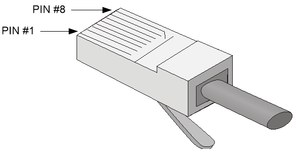
An Ethernet twisted pair cable connects network devices through the RJ-45 connectors at the two ends. Figure1-3 shows the pinouts of an RJ-45 connector.
Figure1-3 RJ-45 connector pinout
|
|
NOTE: The RJ-45 Ethernet ports of the firewall use category 5 or higher Ethernet twisted pair cables for connection. |
EIA/TIA cabling specifications define two standards, 568A and 568B, for cable pinouts.
· Standard 568A—pin 1: white/green stripe, pin 2: green solid, pin 3: white/orange stripe, pin 4: blue solid, pin 5: white/blue stripe, pin 6: orange solid, pin 7: white/brown stripe, pin 8: brown solid.
· Standard 568B—pin 1: white/orange stripe, pin 2: orange solid, pin 3: white/green stripe, pin 4: blue solid, pin 5: white/blue stripe, pin 6: green solid, pin 7: white/brown stripe, pin 8: brown solid.
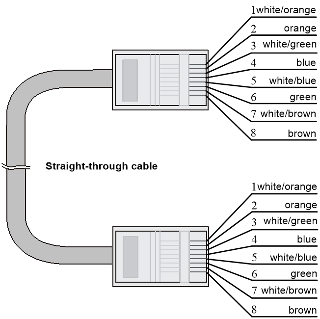
Ethernet twisted pair cables can be classified into straight-through and crossover cables based on their pinouts.
· Straight-through—The pinouts at both ends are T568B compliant, as shown in Figure1-4.
· Crossover—The pinouts are T568B compliant at one end and T568A compliant at the other end, as shown in Figure1-5.
Figure1-4 Straight-through cable

Select an Ethernet twisted pair cable according to the RJ-45 Ethernet port type on your device. An RJ-45 Ethernet port can be MDI (for routers and PCs) or MDIX (for switches). Table1-4 and Table1-5 show their pinouts.
Table1-4 RJ-45 MDI port pinouts
|
Pin |
10BASE-T/100BASE-TX |
1000BASE-T |
||
|
Signal |
Function |
Signal |
Function |
|
|
1 |
Tx+ |
Sends data |
BIDA+ |
Bi-directional data cable A+ |
|
2 |
Tx- |
Sends data |
BIDA- |
Bi-directional data cable A- |
|
3 |
Rx+ |
Receives data |
BIDB+ |
Bi-directional data cable B+ |
|
4 |
Reserved |
N/A |
BIDC+ |
Bi-directional data cable C+ |
|
5 |
Reserved |
N/A |
BIDC- |
Bi-directional data cable C- |
|
6 |
Rx- |
Receives data |
BIDB- |
Bi-directional data cable B- |
|
7 |
Reserved |
N/A |
BIDD+ |
Bi-directional data cable D+ |
|
8 |
Reserved |
N/A |
BIDD- |
Bi-directional data cable D- |
Table1-5 RJ-45 MDIX port pinouts
|
Pin |
10BASE-T/100BASE-TX |
1000BASE-T |
||
|
Signal |
Function |
Signal |
Function |
|
|
1 |
Rx+ |
Receives data |
BIDB+ |
Bi-directional data cable B+ |
|
2 |
Rx- |
Receives data |
BIDB- |
Bi-directional data cable B- |
|
3 |
Tx+ |
Sends data |
BIDA+ |
Bi-directional data cable A+ |
|
4 |
Reserved |
N/A |
BIDD+ |
Bi-directional data cable D+ |
|
5 |
Reserved |
N/A |
BIDD- |
Bi-directional data cable D- |
|
6 |
Tx- |
Sends data |
BIDA- |
Bi-directional data cable A- |
|
7 |
Reserved |
N/A |
BIDC+ |
Bi-directional data cable C+ |
|
8 |
Reserved |
N/A |
BIDC- |
Bi-directional data cable C- |
To ensure normal communication, the pins for sending data on one port must correspond to the pins for receiving data on the peer port. When both of the ports on the two devices are MDI or MDIX, use a crossover Ethernet cable; when one port is MDI and the other is MDIX, use a straight-through Ethernet cable. To summarize, straight-through and crossover cables connect the following devices:
· Straight-through cables connect devices of different types—for example, router to PC and router to switch.
· Crossover cables connect devices of the same type—for example, switch to switch, router to router, and PC to PC.
If an RJ-45 Ethernet port is enabled with MDI/MDIX autosensing, it can automatically negotiate pin roles.
|
|
NOTE: The RJ-45 Ethernet ports on the firewall support MDI/MDIX autosensing. |
Making an Ethernet twisted pair cable
1. Cut the cable to a required length with the crimping tool.
2. Strip off an appropriate length of the cable sheath. The length is typically that of the RJ-45 connector.
3. Untwist the pairs so that they can lay flat, and arrange the colored wires based on the wiring specifications.
4. Cut the top of the wires even with one another. Insert the wires into the RJ-45 connector and make sure the wires extend to the front of the RJ-45 connector and make good contact with the metal contacts in the RJ-45 connector and in the correct order.
5. Crimp the RJ-45 connector with the crimping tool until you hear a click.
6. Use a cable tester to verify the connectivity of the cable.
Optical fiber
Optical fibers feature low loss and long transmission distance.
Optical fibers can be classified into single mode fibers and multi-mode fibers. A single mode fiber (with yellow jacket) carries only a single ray of light; a multi-mode fiber (with orange jacket) carries multiple modes of lights.
Table1-6 Characteristics of single mode and multi-mode optical fibers
|
Item |
Single mode fiber |
Multi-mode fiber |
|
Core |
Small core (10 micrometers or less) |
Larger core than single mode fiber (50 micrometers, 62.5 micrometers or greater) |
|
Dispersion |
Less dispersion |
Allows greater dispersion and therefore, signal loss exists. |
|
Light source and transmission distance |
Uses lasers as the light source often within campus backbones for distance of several thousand meters |
Uses LEDs as the light source often within LANs or distances of a couple hundred meters within a campus network |
Table1-7 Allowed maximum tensile force and crush load
|
Period of force |
Tensile load (N) |
Crush load (N/mm) |
|
Short period |
150 |
500 |
|
Long term |
80 |
100 |
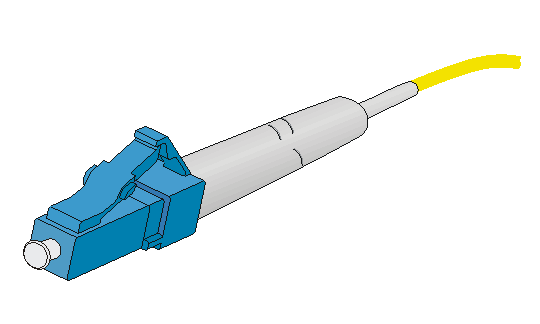
Fiber connectors are indispensable passive components in an optical fiber communication system. They allow the removable connection between optical channels, which makes the optical system debugging and maintenance more convenient. There are multiple types of fiber connectors. Figure1-6 shows an LC connector.
Figure1-6 Appearance of an LC connector
Follow these guidelines when you connect an optical fiber:
· Before connecting an optical fiber, make sure the connector and cable type match the interface module.
· The fiber Ethernet port of the firewall supports only the LC connector.
· Fiber connectors are fitted with dust caps. Keep the dust caps secure when the fiber connectors are in use. Install dust caps when the fiber connectors are not in use to avoid damage to their end face. Replace the dust cap if it is loose or polluted.
· Before connecting an optical fiber, use dust free paper and absolute alcohol to clean the end face of the two fiber connectors. You can brush the end faces only in one direction.
· Never bend or curve a fiber when connecting it.
· If the fiber has to pass through a metallic board hole, when passing through a metallic board hole or bending along the acute side of mechanical parts, the fiber must wear jackets or cushions.