- Table of Contents
- Related Documents
-
| Title | Size | Download |
|---|---|---|
| 03-LEDs | 2.45 MB |
3 LEDs
The MPUs, switching fabric modules, FIPs, SAPs, HIM/MIM/MICs, power supplies, and fan trays available for the router provide various LEDs to indicate the operating status.
Table3-1 H3C SR6616 router LEDs
|
LED |
Remarks |
|
|
RPE-X1 LEDs |
Run LED (RUN) |
See Table3-2. |
|
Active LED (ACT) |
||
|
Alarm LED (ALM) |
||
|
Management Ethernet port LED (LINK/ACT) |
||
|
USB port LED (USB) |
||
|
CF card LED (CF) |
||
|
RPE-X3 LEDs |
Management Ethernet port LED (LINK/ACT) |
See Table3-3. |
|
Alarm LED (ALM) |
||
|
Power alarm LED (PALM) |
||
|
Active LED (ACT) |
||
|
Run LED (RUN) |
||
|
RPE-X5 LEDs |
Run LED (RUN) |
See Table3-4. |
|
Power alarm LED (PALM) |
||
|
IRF LED (IRF) |
||
|
Management Ethernet port LED (MANAGEMENT) |
||
|
Alarm LED (ALM) |
||
|
Active LED (ACT) |
||
|
RPE-X5E LEDs |
Run LED (RUN) |
See Table3-5. |
|
Power alarm LED (PALM) |
||
|
IRF LED (IRF) |
||
|
10GBASE-R-SFP+ port (SFP+0 and SFP+1) |
||
|
Management Ethernet port LED (MANAGEMENT) |
||
|
Alarm LED (ALM) |
||
|
Active LED (ACT) |
||
|
Power button |
||
|
RSE-X1 LEDs |
Run LED (RUN) |
See Table3-6. |
|
Active LED (ACT) |
||
|
Alarm LED (ALM) |
||
|
Power alarm LED (PALM) |
||
|
Management Ethernet port LED (LINK/ACT) |
||
|
USB port LED (USB) |
||
|
CF card LED (CF) |
||
|
MCP-X1 LEDs |
10/100/1000 Mbps copper Ethernet port LEDs (GE0 through GE3) |
See Table3-7. |
|
CF card LED (CF) |
||
|
Run LED (RUN) |
||
|
Active LED (ACT) |
||
|
Power alarm LED (PALM) |
||
|
Alarm LED (ALM) |
||
|
Management Ethernet port LED (LINK/ACT) |
||
|
1000 Mbps fiber Ethernet port LED (SFP0 through SFP3) |
||
|
MCP-X2 LEDs |
10/100/1000 Mbps copper Ethernet port LEDs (GE0 through GE3) |
See Table3-8. |
|
CF card LED (CF) |
||
|
Run LED (RUN) |
||
|
Active LED (ACT) |
||
|
Power alarm LED (PALM) |
||
|
Alarm LED (ALM) |
||
|
Management Ethernet port LED (LINK/ACT) |
||
|
10 Gbps Ethernet port LED (SFP+LINK/ACT) |
||
|
1000 Mbps fiber Ethernet port LED (SFP0 through SFP3) |
||
|
Switching fabric module LEDs |
Run LED (RUN) |
See Table3-9. |
|
FIP LEDs |
Run LED (RUN) |
|
|
10/100/1000 Mbps copper Ethernet port LED (GE0 and GE1) |
||
|
1000 Mbps fiber Ethernet port LED (SFP0 and SFP1) |
||
|
SAP LEDs |
Run LED (RUN) |
|
|
10/100/1000 Mbps Ethernet port LED |
||
|
HIM/MIM/MIC/MIC-X LEDs |
See H3C SR6600/SR6600-X Routers Interface Module Guide. |
|
|
Power supply LEDs |
Power LED |
See Table3-24. |
|
Fan tray LEDs |
Run LED (RUN) |
See Table3-25. |
|
Alarm LED (ALM) |
||
MPU LEDs
|
CAUTION: To avoid damaging the file system on the CF card, do not remove the CF card when the CF LED is flashing. |
Figure3-1 RPE-X1 LEDs
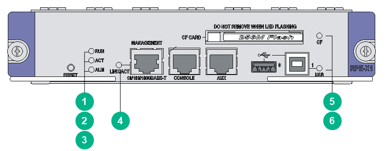
Table3-2 RPE-X1 LED description
|
LED |
Status |
Description |
|
|
(green) |
RUN |
Off |
No power input is available, or the RPE-X1 has failed. |
|
Slow flashing (1 Hz) |
The RPE-X1 is operating correctly. |
||
|
Fast flashing (8 Hz) |
The application software is being loaded (in this case, never power off the device or hot-swap the RPE-X1; otherwise the RPE-X1 might be damaged). |
||
|
(green) |
ACT |
Off |
The RPE-X1 is in standby state. |
|
Steady on |
The RPE-X1 is in active state. |
||
|
(red) |
ALM |
Off |
The system is operating correctly and no alarm has occurred. |
|
Steady on |
A fault has occurred on the system or the available power is insufficient. In this state, identify the system log immediately. |
||
|
Fast flashing (8 Hz) |
A critical fault has occurred to the system. In this state, handle the fault immediately. |
||
|
(yellow/green) |
LINK/ACT |
Steady yellow |
A 10/100 Mbps link is present. |
|
Steady green |
A 1000 Mbps link is present. |
||
|
Flashing yellow |
Data is being received or transmitted at 10/100 Mbps. |
||
|
Flashing green |
Data is being received or transmitted at 1000 Mbps. |
||
|
(green) |
CF |
Off |
No CF card is present or the CF card is not recognizable. |
|
Steady on |
A CF card is in position and has been detected. |
||
|
Flashing |
The system is accessing the CF card. In this state, do not remove the CF card. |
||
|
(green) |
USB |
Off |
No host is connected to the device-mode USB port. |
|
Steady on |
A host is connected to the device-mode USB port. The USB cable can be unplugged in this state. |
||
|
Flashing |
Data is being transmitted or received through the device-mode USB port. In this state, do not unplug the USB cable. |
||
Figure3-2 RPE-X3 LEDs
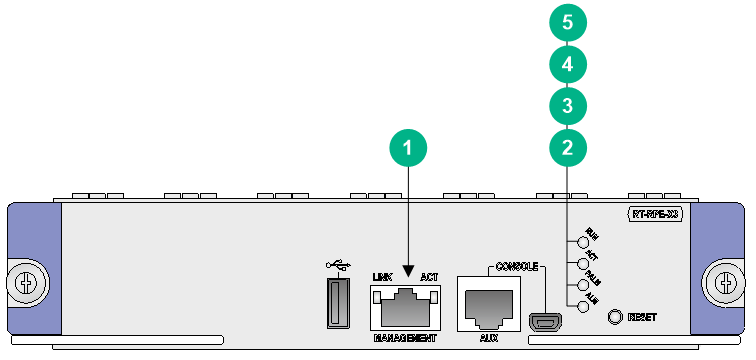
Table3-3 RPE-X3 LED description
|
LED |
Status |
Description |
|
|
(yellow/green) |
LINK/ACT |
Steady yellow |
A 10/100 Mbps link is present. |
|
Steady green |
A 1000 Mbps link is present. |
||
|
Flashing yellow |
Data is being received or transmitted at 10/100 Mbps. |
||
|
Flashing green |
Data is being received or transmitted at 1000 Mbps. |
||
|
(red) |
ALM |
Off |
The system is operating correctly and no alarm has occurred. |
|
Steady on |
A fault has occurred on the system. |
||
|
Fast flashing (8 Hz) |
A critical fault has occurred to the system. |
||
|
(red) |
PALM |
Off |
The power system is operating correctly. |
|
Steady on |
The available power is insufficient. |
||
|
(green) |
ACT |
Off |
The MPU is in standby state. |
|
Steady on |
The MPU is in active state. |
||
|
(green) |
RUN |
Off |
No power input is available, or the MPU has failed. |
|
Slow flashing (1 Hz) |
The MPU is operating correctly. |
||
|
Fast flashing (8 Hz) |
The system software is being loaded. To avoid damage to the MPU, never power off the device or hot-swap the MPU. |
||
Figure3-3 LEDs on the RPE-X5
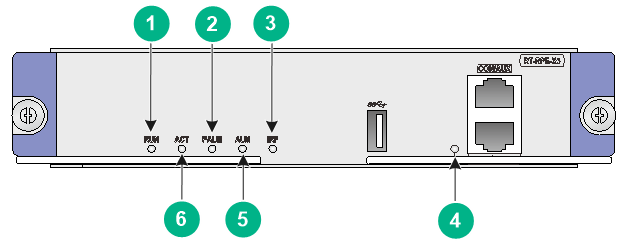
Table3-4 RPE-X5 LED description
|
LED |
Status |
Description |
||
|
(yellow/green) |
RUN |
Fast flashing green |
BIOS stage |
The BIOS is operating correctly. |
|
Slow flashing yellow |
No or insufficient memory or initialization failure. |
|||
|
Fast flashing yellow |
The extended segment does not exist. |
|||
|
Off |
Hardware failure or no power input. |
|||
|
Steady green |
BootWare stage |
The SDRAM is performing self-test. |
||
|
Fast flashing green |
The BootWare runs. |
|||
|
Slow flashing green |
The Comware system has started with the configuration file and the system is operating correctly. |
|||
|
Steady yellow |
The boot image does not exist. |
|||
|
Slow flashing yellow |
The SDRAM has failed the self-test. |
|||
|
Off |
Hardware failure or no power input. |
|||
|
Slow flashing green |
Comware stage |
The system is operating correctly. |
||
|
Fast flashing green (5 seconds) |
USB-based automatic configuration has succeeded. |
|||
|
(red) |
PALM |
Steady on |
The system power is insufficient. |
|
|
Off |
The power system is operating correctly. |
|||
|
(yellow/green) |
IRF |
Slow flashing green |
The device is in IRF mode and the MPU is the global active MPU. |
|
|
Steady green |
The device is in IRF mode and the MPU is a standby MPU. |
|||
|
Steady yellow |
The device is in IRF mode but the IRF configuration has failed. |
|||
|
Off |
The device is in standalone mode. |
|||
|
(yellow/green) |
MANAGEMENT |
Steady green |
A 1000 Mbps link is present. |
|
|
Flashing green |
Data is being received or transmitted at 1000 Mbps. |
|||
|
Steady yellow |
A 100 Mbps link is present. |
|||
|
Flashing yellow |
Data is being received or transmitted at 100 Mbps. |
|||
|
Off |
No link is present or the port is faulty. |
|||
|
(red) |
ALM |
Fast flashing (10 seconds) |
USB-based automatic configuration has failed. |
|
|
Steady on |
A fault has occurred on the system. |
|||
|
Off |
The system is operating correctly and no alarm has occurred. |
|||
|
(green) |
ACT |
Steady on |
The MPU is in active state. |
|
|
Off |
The MPU is in standby state. |
|||
Figure3-4 LEDs on the RPE-X5E
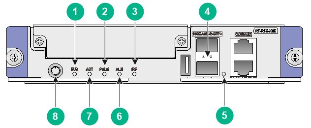
Table3-5 RPE-X5E LED description
|
LED |
Status |
Description |
|||
|
(yellow/green) |
RUN |
Fast flashing green |
BIOS stage |
The BIOS is operating correctly. |
|
|
Slow flashing yellow |
No or insufficient memory or initialization failure. |
||||
|
Fast flashing yellow |
The extended segment does not exist. |
||||
|
Off |
Hardware failure or no power input. |
||||
|
Steady green |
BootWare stage |
The SDRAM is performing self-test. |
|||
|
Fast flashing green |
The BootWare runs. |
||||
|
Slow flashing green |
The Comware system has started with the configuration file and the system is operating correctly. |
||||
|
Steady yellow |
The boot image does not exist. |
||||
|
Slow flashing yellow |
The SDRAM has failed the self-test. |
||||
|
Off |
Hardware failure or no power input. |
||||
|
Slow flashing green |
Comware stage |
The system is operating correctly. |
|||
|
Fast flashing green (5 seconds) |
USB-based automatic configuration has succeeded. |
||||
|
(red) |
PALM |
Steady on |
The system power is insufficient. |
||
|
Off |
The power system is operating correctly. |
||||
|
(yellow/green) |
IRF |
Slow flashing green |
The device is in IRF mode and the MPU is the global active MPU. |
||
|
Steady green |
The device is in IRF mode and the MPU is a standby MPU. |
||||
|
Steady yellow |
The device is in IRF mode but the IRF configuration has failed. |
||||
|
Off |
The device is in standalone mode. |
||||
|
(green) |
SFP+0 and SFP+1 |
Steady green |
NOTE: After a link is set up, using the command to bring up or shut down the port does not change the LED status. |
A 10 Gbps link is present. |
|
|
Flashing green |
Data is being received or transmitted at 10000 Mbps. |
||||
|
Off |
No link is present. |
||||
|
(yellow/green) |
MANAGEMENT |
Steady green |
A 1000 Mbps link is present. |
||
|
Flashing green |
Data is being received or transmitted at 1000 Mbps. |
||||
|
Steady yellow |
A 100 Mbps link is present. |
||||
|
Flashing yellow |
Data is being received or transmitted at 100 Mbps. |
||||
|
Off |
No link is present or the port is faulty. |
||||
|
(red) |
ALM |
Fast flashing (10 seconds) |
USB-based automatic configuration has failed. |
||
|
Steady on |
A fault has occurred on the system. |
||||
|
Off |
The system is operating correctly and no alarm has occurred. |
||||
|
(green) |
ACT |
Steady on |
The MPU is in active state. |
||
|
Off |
The MPU is in standby state. |
||||
|
(red/green) |
Power button |
Fast flashing red |
The MPU has been powered up to start up the Comware system. |
||
|
Slow flashing red |
The BIOS is starting up. |
||||
|
Slow flashing green |
The BootWare is starting up. |
||||
|
Steady green |
The Comware system starts up and is operating correctly. |
||||
|
Fast flashing green |
The power button has been pressed and the Comware system starts to shut down. |
||||
|
Steady red |
The shutdown of the Comware system is in progress. |
||||
|
Off |
The Comware system has shut down. |
||||
Figure3-5 RSE-X1 LEDs
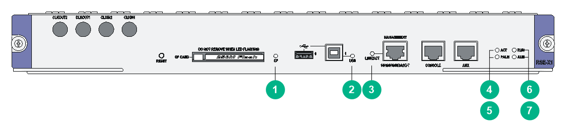
Table3-6 RSE-X1 LED description
|
LED |
Status |
Description |
|
|
(green) |
CF |
Off |
No CF card is present or the CF card is not recognizable. |
|
Steady on |
A CF card is in position and has been detected. |
||
|
Flashing |
The system is accessing the CF card. In this state, do not remove the CF card. |
||
|
(green) |
USB |
Off |
No host is connected to the device-mode USB port. |
|
Steady on |
A host is connected to the device-mode USB port. The USB cable can be unplugged in this state. |
||
|
Flashing |
Data is being transmitted or received through the device-mode USB port. In this state, do not unplug the USB cable. |
||
|
|
LINK/ACT |
Steady yellow |
A 10/100 Mbps link is present. |
|
Steady green |
A 1000 Mbps link is present. |
||
|
Flashing yellow |
Data is being received or transmitted at 10/100 Mbps. |
||
|
Flashing green |
Data is being received or transmitted at 1000 Mbps. |
||
|
(green) |
ACT |
Off |
The RSE-X1 is in the standby state. |
|
Steady on |
The RSE-X1 is in the active state. |
||
|
(red) |
PALM |
Off |
The power system is operating correctly. |
|
Steady on |
The system power is insufficient. |
||
|
(green) |
RUN |
Off |
No power input is available, or the RSE-X1 has failed. |
|
Slow flashing (1 Hz) |
The RSE-X1 is operating correctly. |
||
|
Fast flashing (8 Hz) |
The application software is being loaded (in this case, never power off the device or hot-swap the RSE-X1; otherwise the RSE-X1 might be damaged). |
||
|
(red) |
ALM |
Off |
The system is operating correctly and no alarm has occurred. |
|
Steady on |
A fault has occurred on the system or the available power is insufficient. In this state, identify the system log immediately. |
||
|
Fast flashing (8 Hz) |
A critical fault has occurred to the system. In this state, handle the fault immediately. |
||
Figure3-6 MCP-X1 LEDs
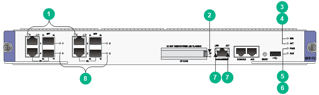
Table3-7 MCP-X1 LED description
|
LED |
Status |
Description |
|
|
(yellow/green) |
GE0 through GE3 |
Off |
The corresponding interface is not connected. |
|
Steady green |
A 1000 Mbps link is present. |
||
|
Flashing green |
Data is being received or transmitted at 1000 Mbps. |
||
|
Steady yellow |
A 10/100 Mbps link is present. |
||
|
Flashing yellow |
Data is being received or transmitted at 10/100 Mbps. |
||
|
(yellow/green) |
CF |
Off |
No CF card is present or the CF card is not recognizable. |
|
Steady green |
A CF card is in position and has been detected. |
||
|
Flashing green |
The system is accessing the CF card. In this state, do not remove the CF card. |
||
|
Steady yellow |
A CF card not provided by H3C. |
||
|
(green) |
RUN |
Off |
No power input is available, or the MCP-X1 has failed. |
|
Slow flashing (1 Hz) |
The MCP-X1 is operating correctly. |
||
|
Fast flashing (8 Hz) |
The application software is being loaded (in this case, never power off the device or hot-swap the MCP-X1; otherwise the MCP-X1 might be damaged). |
||
|
(green) |
ACT |
Off |
The MCP-X1 is in standby state. |
|
Steady on |
The MCP-X1 is in active state. |
||
|
(red) |
PALM |
Off |
The system power supply is normal. |
|
Steady on |
The system power is insufficient. |
||
|
(red) |
ALM |
Off |
The system is operating correctly and no alarm has occurred. |
|
Steady on |
A fault has occurred on the system or the available power is insufficient. In this state, identify the system log immediately. |
||
|
|
LINK/ACT |
Off |
The corresponding interface is not connected. |
|
Steady green |
A 1000 Mbps link is present. |
||
|
Flashing green |
Data is being received or transmitted at 1000 Mbps. |
||
|
Steady yellow |
A 10/100 Mbps link is present. |
||
|
Flashing yellow |
Data is being received or transmitted at 10/100 Mbps. |
||
|
(yellow/green) |
SFP0 through SFP3 |
Off |
No link is present. |
|
Steady green |
A 1000 Mbps link is present. |
||
|
Flashing green |
Data is being received or transmitted at 1000 Mbps. |
||
|
Steady yellow |
A 100 Mbps link is present. |
||
|
Flashing yellow |
Data is being received or transmitted at 100 Mbps. |
||
Figure3-7 MCP-X2 LEDs
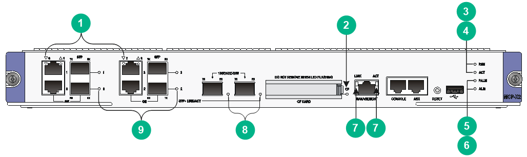
Table3-8 MCP-X2 LED description
|
LED |
Status |
Description |
|
|
(yellow/green) |
GE0 through GE3 |
Off |
The corresponding interface is not connected. |
|
Steady green |
A 1000 Mbps link is present. |
||
|
Flashing green |
Data is being received or transmitted at 1000 Mbps. |
||
|
Steady yellow |
A 10/100 Mbps link is present. |
||
|
Flashing yellow |
Data is being received or transmitted at 10/100 Mbps. |
||
|
(yellow/green) |
CF |
Off |
No CF card is present or the CF card is not recognizable. |
|
Steady green |
A CF card is in position and has been detected. |
||
|
Flashing green |
The system is accessing the CF card. In this state, do not remove the CF card. |
||
|
Steady yellow |
A CF card not provided by H3C. |
||
|
(green) |
RUN |
Off |
No power input is available, or the MCP-X1 has failed. |
|
Slow flashing (1 Hz) |
The MCP-X1 is operating correctly. |
||
|
Fast flashing (8 Hz) |
The application software is being loaded (in this case, never power off the device or hot-swap the MCP-X1; otherwise the MCP-X1 might be damaged). |
||
|
(green) |
ACT |
Off |
The MCP-X1 is in standby state. |
|
Steady on |
The MCP-X1 is in active state. |
||
|
(red) |
PALM |
Off |
The system power supply is normal. |
|
Steady on |
The system power is insufficient. |
||
|
(red) |
ALM |
Off |
The system is operating correctly and no alarm has occurred. |
|
Steady on |
A fault has occurred on the system or the available power is insufficient. In this state, identify the system log immediately. |
||
|
|
LINK |
Off |
The corresponding interface is not connected. |
|
Steady green |
A 1000 Mbps link is present. |
||
|
Steady yellow |
A 10/100 Mbps link is present. |
||
|
ACT |
Off |
No data is being received or transmitted. |
|
|
Flashing yellow |
Data is being received or transmitted. |
||
|
(yellow/green) |
SFP+LINK/ACT |
Off |
No link is present. |
|
Steady green |
A 10 Gbps link is present. |
||
|
Flashing green |
Data is being received or transmitted at 10 Gbps. |
||
|
Steady yellow |
Transceiver module check has failed. |
||
|
(yellow/green) |
SFP0 through SFP3 |
Off |
No link is present. |
|
Steady green |
A 1000 Mbps link is present. |
||
|
Flashing green |
Data is being received or transmitted at 1000 Mbps. |
||
|
Steady yellow |
A 100 Mbps link is present. |
||
|
Flashing yellow |
Data is being received or transmitted at 100 Mbps. |
||
Switching fabric module LEDs
Figure3-8 SFE-L1 status LED
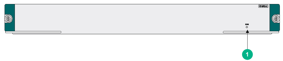
Figure3-9 SFE-2 status LED
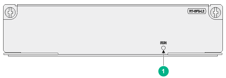
Table3-9 SFE-L1 LED description
|
LED |
Status |
Description |
|
|
(green) |
RUN |
Off |
No link is present or the module is faulty. |
|
Slow flashing (1 Hz) |
The module is operating correctly. |
||
|
Fast flashing (8 Hz) |
Application software is being loaded. To avoid module damage, do not power off the device or hot-swap the module while the application software is being loaded. |
||
FIP LEDs
Figure3-10 FIP-10 LED
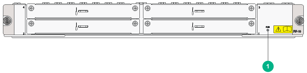
Figure3-11 FIP-20 LED

Table3-10 FIP-10/20 LED description
|
LED |
Status |
Description |
|
|
(green) |
RUN |
Off |
No link is present or the FIP is faulty. |
|
Slow flashing (1 Hz) |
The FIP is operating correctly. |
||
|
Fast flashing (8 Hz) |
The FIP is loading software. |
||
Figure3-12 FIP-110 LEDs
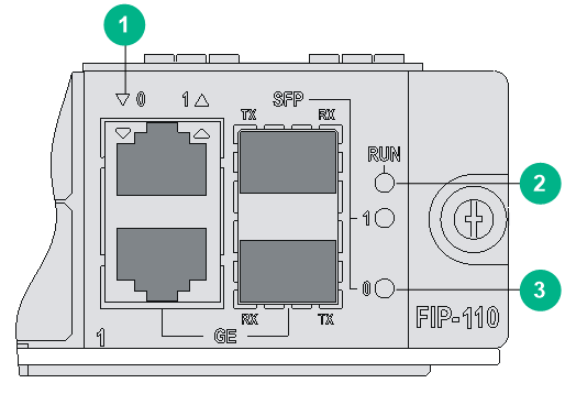
Figure3-13 FIP-210 LEDs
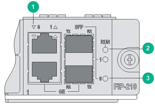
Figure3-14 FIP-240 LEDs
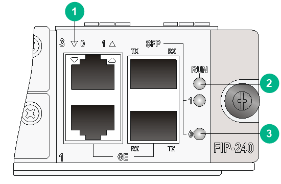
Figure3-15 FIP-600 LEDs
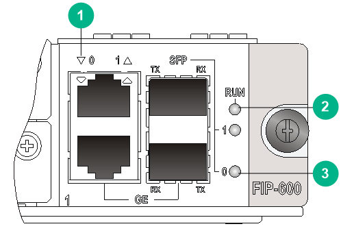
Table3-11 FIP-110/210/240/600 LED description
|
LED |
Status |
Description |
|
|
(yellow/green) |
10/100/1000 Mbps copper Ethernet port |
Off |
No link is present. |
|
Steady green |
A 1000 Mbps link is present. |
||
|
Flashing green |
Data is being received or transmitted at 1000 Mbps. |
||
|
Steady yellow |
A 10/100 Mbps link is present. |
||
|
Flashing yellow |
Data is being received or transmitted at 10/100 Mbps. |
||
|
(green) |
RUN |
Off |
No power is being input or the FIP has failed. |
|
Slow flashing (1 Hz) |
The FIP is operating correctly. |
||
|
Fast flashing (8 Hz) |
The FIP is loading software. |
||
|
(yellow/green) |
1000 Mbps fiber Ethernet port LED |
Off |
No link is present. |
|
Steady green |
A link is present. |
||
|
Flashing green |
Data is being sent or received at 1000 Mbps. |
||
|
Steady yellow |
The transceiver module failed to be detected. |
||
Figure3-16 FIP-260 LEDs

Table3-12 FIP-260 LED description
|
LED |
Status |
Description |
|
|
(green) |
RUN |
Off |
No power is being input or the FIP has failed. |
|
On |
The FIP software system is starting up. |
||
|
Slow flashing (1 Hz) |
The FIP is operating correctly. |
||
|
Fast flashing (8 Hz) |
The FIP is loading software. |
||
Figure3-17 FIP-300 LEDs
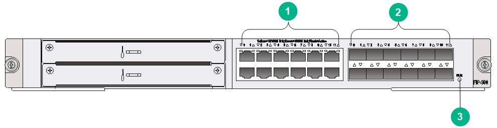
Table3-13 FIP-300 LED description
|
LED |
Status |
Description |
|
|
(yellow/green) |
GE0 through GE11 |
Off |
No link is present or the interface fails. |
|
Steady green |
A 1000 Mbps link is present. |
||
|
Flashing green |
Data is being received or transmitted at 1000 Mbps. |
||
|
Steady yellow |
A 10/100 Mbps link is present. |
||
|
Flashing yellow |
Data is being received or transmitted at 10/100 Mbps. |
||
|
(yellow/green) |
SFP0 through SFP11 |
Off |
No link is present. |
|
Steady green |
A 1000 Mbps link is present. |
||
|
Flashing green |
Data is being received or transmitted at 1000 Mbps. |
||
|
Steady yellow |
POST has failed. |
||
|
(green) |
RUN |
Off |
No power input is available or the FIP has failed. |
|
Slow flashing (1 Hz) |
The FIP is operating correctly. |
||
|
Fast flashing (8 Hz) |
System software is being loaded. To avoid damage to the FIP, never power off the device or hot-swap the FIP. |
||
Figure3-18 FIP-310 LEDs
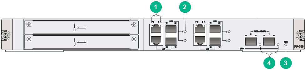
Table3-14 FIP-310 LED description
|
LED |
Status |
Description |
|
|
(yellow/green) |
GE0 through GE3 |
Off |
No link is present. |
|
Steady green |
A 1000 Mbps link is present. |
||
|
Flashing green |
Data is being received or transmitted at 1000 Mbps. |
||
|
Steady yellow |
A 10/100 Mbps link is present. |
||
|
Flashing yellow |
Data is being received or transmitted at 10/100 Mbps. |
||
|
(yellow/green) |
SFP0 through SFP3 |
Off |
No link is present. |
|
Steady green |
A 1000 Mbps link is present. |
||
|
Flashing green |
Data is being received or transmitted at 1000 Mbps. |
||
|
Steady yellow |
POST has failed. |
||
|
(green) |
RUN |
Off |
No power input is available or the FIP has failed. |
|
Slow flashing (1 Hz) |
The FIP is operating correctly. |
||
|
Fast flashing (8 Hz) |
System software is being loaded. To avoid damage to the FIP, never power off the device or hot-swap the FIP. |
||
|
(yellow/green) |
SFP+ |
Off |
No link is present. |
|
Steady green |
A 10 Gbps link is present. |
||
|
Flashing green |
Data is being received or transmitted at 10 Gbps. |
||
|
Steady yellow |
POST has failed. |
||
Figure3-19 FIP-380 LEDs
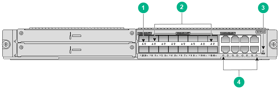
Table3-15 FIP-380 LED description
|
LED |
Status |
Description |
|
|
(yellow/green) |
SFP+22 and SFP+23 |
Off |
No link is present on the port or the port is faulty. |
|
Steady yellow |
A 1000 Mbps link is present on the port. |
||
|
Flashing yellow (8 Hz) |
The port is sending and receiving data at 1000 Mbps. |
||
|
Steady green |
A 10 Gbps link is present on the port. |
||
|
Flashing green (8 Hz) |
The port is sending and receiving data at 10 Gbps. |
||
|
(yellow/green) |
SFP0 to SFP13 |
Off |
No link is present on the port or the port is faulty. |
|
Steady yellow |
A 100 Mbps link is present on the port. |
||
|
Flashing yellow (8 Hz) |
The port is sending and receiving data at 100 Mbps. |
||
|
Steady green |
A 1000 Mbps link is present on the port. |
||
|
Flashing green (8 Hz) |
The port is sending and receiving data at 1000 Mbps. |
||
|
(green) |
RUN |
Off |
No power is being input or the FIP has failed. |
|
Steady green |
The FIP software system is starting up. |
||
|
Flashing green (1 Hz) |
The FIP is operating correctly. |
||
|
Flashing green (8 Hz) |
The FIP is loading software. |
||
|
(yellow and green) |
GE14 to GE21 |
Off |
The port is not connected or is faulty. |
|
Steady yellow |
A 100 Mbps link is present on the port. |
||
|
Flashing yellow (8 Hz) |
The port is sending and receiving data at 100 Mbps. |
||
|
Steady green |
A 1000 Mbps link is present on the port. |
||
|
Flashing green (8 Hz) |
The port is sending and receiving data at 1000 Mbps. |
||
Figure3-20 FIP-660 LEDs
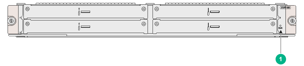
Table3-16 FIP-660 LED description
|
LED |
Status |
Description |
|
|
(green) |
RUN |
Off |
No power input is available or the FIP-660 has failed. |
|
Fast flashing green (8 Hz) |
System software is being loaded. |
||
|
Steady green |
The FIP software system is starting up. |
||
|
Slow flashing green (1 Hz) |
The FIP is operating correctly. |
||
Figure3-21 FIP-680 LEDs
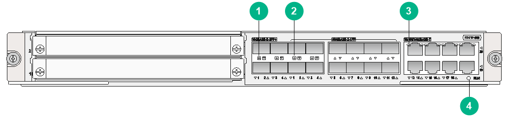
Table3-17 FIP-680 LED description
|
LED |
Status |
Description |
|
|
(green) |
SFP1 through SFP12 |
Off |
No link is present. |
|
Steady green |
A 1000 Mbps link is present. |
||
|
Flashing green |
Data is being received or transmitted at 1000 Mbps. |
||
|
(green) |
SFP+1 through SFP+4 |
Off |
No link is present. |
|
Steady green |
A 10 Gbps link is present. |
||
|
Flashing green |
Data is being received or transmitted at 10 Gbps. |
||
|
(yellow/green) |
GE13 through GE20 |
Off |
No link is present or the port is faulty. |
|
Steady green |
A 1000 Mbps link is present. |
||
|
Flashing green |
Data is being received or transmitted at 1000 Mbps. |
||
|
Steady yellow |
A 10/100 Mbps link is present. |
||
|
Flashing yellow |
Data is being received or transmitted at 10/100 Mbps. |
||
|
(green) |
Module status LED (RUN) |
Off |
No power input is available or the FIP has failed. |
|
Slow flashing (1 Hz) |
The FIP is operating correctly. |
||
|
Fast flashing (8 Hz) |
System software is being loaded. To avoid damage to the FIP, never power off the device or hot-swap the FIP when the system software is being loaded. |
||
SAP LEDs
Figure3-22 SAP LEDs(SAP-48GBE)
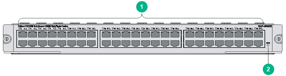
Table3-18 SAP-48GBE LED description
|
Item |
Status |
Description |
|
|
(yellow/green) |
Status LEDs of GE 0 through GE 47 |
Off |
No link is present. |
|
Steady green |
A 1000 Mbps link is present. |
||
|
Flashing green |
Data is being received or transmitted at 1000 Mbps. |
||
|
Steady yellow |
A 10/100 Mbps link is present. |
||
|
Flashing yellow |
Data is being received or transmitted at 10/100 Mbps. |
||
|
(green) |
RUN |
Off |
No power input is available or the SAP-48GBE has failed. |
|
Slow flashing (1 Hz) |
The SAP-48GBE is operating correctly. |
||
|
Fast flashing (8 Hz) |
Application program is being loaded (in this case, never power off the device or hot-swap the SAP-48GBE; otherwise, the SAP-48GBE might be damaged), or the SAP-48GBE is not working. |
||
Figure3-23 SAP LEDs(SAP-24GBP)
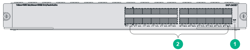
Table3-19 SAP-24GBP LED description
|
LED |
Status |
Description |
|
|
(green) |
RUN |
Off |
No power input is available or the SAP-24GBP has failed. |
|
Slow flashing (1 Hz) |
The SAP-24GBP is operating correctly. |
||
|
Fast flashing (8 Hz) |
Application program is being loaded (in this case, never power off the device or hot-swap the SAP-24GBP; otherwise, the SAP-24GBP might be damaged), or the SAP-24GBP is not working. |
||
|
(yellow/green) |
Status LEDs of SFP 0 to SFP 23 |
Off |
No link is present. |
|
Steady green |
A 1000 Mbps link is present. |
||
|
Flashing green |
Data is being received or transmitted at 1000 Mbps. |
||
|
Steady yellow |
A 100 Mbps link is present. |
||
|
Flashing yellow |
Data is being received or transmitted at 100 Mbps. |
||
Figure3-24 SAP-48GBP LEDs

Table3-20 SAP-48GBP LED description
|
LED |
Status |
Description |
|
|
(yellow/green) |
Status LEDs of SFP 0 to SFP 47 |
Off |
No link is present. |
|
Steady green |
A 1000 Mbps link is present. |
||
|
Flashing green |
Data is being received or transmitted at 1000 Mbps. |
||
|
Steady yellow |
A 100 Mbps link is present. |
||
|
Flashing yellow |
Data is being received or transmitted at 100 Mbps. |
||
|
(green) |
System status LED |
Off |
No power input is available or the SAP-48GBP has failed. |
|
Slow flashing (1 Hz) |
The SAP-48GBP is operating correctly. |
||
|
Fast flashing (8 Hz) |
Application program is being loaded (in this case, never power off the device or hot-swap the SAP-48GBP. Otherwise, the SAP-48GBP might be damaged), or the SAP-48GBP is not working. |
||
Figure3-25 SAP-20GE2XP LEDs
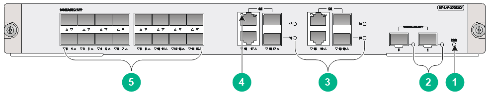
Table3-21 SAP-20GE2XP LED description
|
LED |
Status |
Description |
|
|
(green) |
RUN |
Off |
No power input is available or the SAP-20GE2XP has failed. |
|
Slow flashing (1 Hz) |
The SAP-20GE2XP is operating correctly. |
||
|
Fast flashing (8 Hz) |
System software is being loaded or the SAP-20GE2XP is not operating.
To avoid hardware damage, do not power off the router, or insert or remove the SAP-20GE2XP when system software is being loaded. |
||
|
(yellow/green) |
Status LEDs for SFP+ port 0 and SFP+ port 1 |
Off |
No link is present. |
|
Steady green |
A 10 Gbps link is present. |
||
|
Flashing green |
Data is being received or transmitted at 10 Gbps. |
||
|
Steady yellow |
The transceiver module has failed to be detected. |
||
|
(yellow/green) |
Status LEDs for fiber combo ports GE16 to GE19 |
Off |
No link is present. |
|
Steady green |
A 1000 Mbps link is present. |
||
|
Flashing green |
Data is being received or transmitted at 1000 Mbps. |
||
|
Steady yellow |
A 100 Mbps link is present. |
||
|
Flashing yellow |
Data is being received or transmitted at 100 Mbps. |
||
|
(yellow/green) |
Status LEDs for copper combo ports GE16 to GE19 |
Off |
No link is present. |
|
Steady green |
A 1000 Mbps link is present. |
||
|
Flashing green |
Data is being received or transmitted at 1000 Mbps. |
||
|
Steady yellow |
A 10/100 Mbps link is present. |
||
|
Flashing yellow |
Data is being received or transmitted at 10/100 Mbps. |
||
|
(yellow/green) |
Status LEDs for SFP ports GE0 to GE15 |
Off |
No link is present. |
|
Steady green |
A 1000 Mbps link is present. |
||
|
Flashing green |
Data is being received or transmitted at 1000 Mbps. |
||
|
Steady yellow |
A 100 Mbps link is present. |
||
|
Flashing yellow |
Data is being received or transmitted at 100 Mbps. |
||
Figure3-26 SAP-28GE LEDs

Table3-22 SAP-28GE LED description
|
LED |
Status |
Description |
|
|
(green) |
RUN |
Off |
No power input is available or the SAP-28GE has failed. |
|
Slow flashing (1 Hz) |
The SAP-28GE is operating correctly. |
||
|
Fast flashing (8 Hz) |
System software is being loaded or the SAP-28GE is not operating.
To avoid hardware damage, do not power off the router, or insert or remove the SAP-28GE when system software is being loaded. |
||
|
(yellow/green) |
Status LEDs for fiber combo ports GE16 to GE27 |
Off |
No link is present. |
|
Steady green |
A 1000 Mbps link is present. |
||
|
Flashing green |
Data is being received or transmitted at 1000 Mbps. |
||
|
Steady yellow |
A 100 Mbps link is present. |
||
|
Flashing yellow |
Data is being received or transmitted at 100 Mbps. |
||
|
(yellow/green) |
Status LEDs for copper combo ports GE16 to GE27 |
Off |
No link is present. |
|
Steady green |
A 1000 Mbps link is present. |
||
|
Flashing green |
Data is being received or transmitted at 1000 Mbps. |
||
|
Steady yellow |
A 10/100 Mbps link is present. |
||
|
Flashing yellow |
Data is being received or transmitted at 10/100 Mbps. |
||
|
(yellow/green) |
Status LEDs for SFP ports GE0 to GE15 |
Off |
No link is present. |
|
Steady green |
A 1000 Mbps link is present. |
||
|
Flashing green |
Data is being received or transmitted at 1000 Mbps. |
||
|
Steady yellow |
A 100 Mbps link is present. |
||
|
Flashing yellow |
Data is being received or transmitted at 100 Mbps. |
||
Figure3-27 SAP-XP4GE32 LEDs
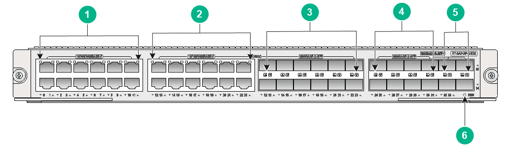
Table3-23 SAP-XP4GE32 LED description
|
LED |
Status |
Description |
|
|
(yellow/green) |
· GE0 through GE11 · GE12 through GE23 (copper combo port) |
Off |
No link is present, or the port is faulty. |
|
Steady yellow |
A 10/100 Mbps link is present. |
||
|
Flashing yellow (8 Hz) |
Data is being received or transmitted at 10/100 Mbps. |
||
|
Steady green |
A 1000 Mbps link is present. |
||
|
Flashing green (8 Hz) |
Data is being received or transmitted at 1000 Mbps. |
||
|
(yellow/green) |
· SFP12 through SFP23 (fiber combo port) · SFP24 through SFP31 |
Off |
No link is present, or the port is faulty |
|
Steady yellow |
A 100 Mbps link is present. |
||
|
Flashing yellow (8 Hz) |
Data is being received or transmitted at 100 Mbps. |
||
|
Steady green |
A 1000 Mbps link is present. |
||
|
Flashing green (8 Hz) |
Data is being received or transmitted at 1000 Mbps. |
||
|
|
SFP+32 through SFP+35 |
Off |
No link is present or the port is faulty. |
|
Steady green |
A 10 Gbps link is present. |
||
|
Flashing green (8 Hz) |
Data is being received or transmitted at 10 Gbps. |
||
|
(green) |
RUN |
Off |
No power input is available or the SAP-XP4GE32 has failed. |
|
Slow flashing green (1 Hz) |
The SAP-28GE is operating correctly. |
||
|
Fast flashing green (8 Hz) |
System software is being loaded or the SAP-28GE is not operating.
To avoid hardware damage, do not power off the router, or insert or remove the SAP-28GE when system software is being loaded. |
||
HIM/MIM/MIC/MIC-X LEDs
For HIM/MIM/MIC/MIC-X LED description, see H3C SR6600/SR6600-X Routers Interface Module Guide.
Power supply LEDs
Figure3-28 PSR650-A AC power supply LED
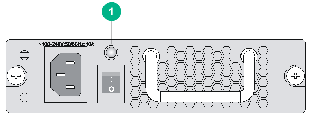
Figure3-29 PSR1200-A AC power supply LED
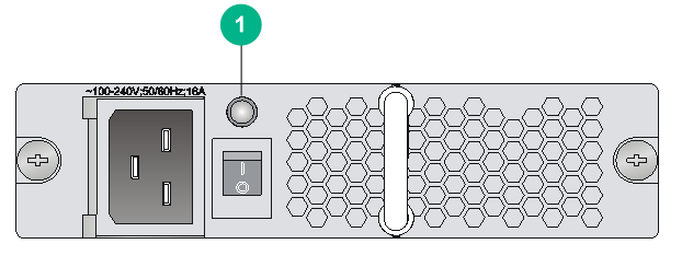
Figure3-30 PSR650-D DC power supply LED
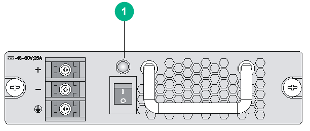
Figure3-31 PSR1200-D DC power supply LED

Table3-24 AC/DC power LED description
|
LED |
Status |
Description |
|
|
|
Power LED |
Steady green |
The power supply is operating correctly. |
|
Steady red |
The power supply is faulty. |
||
|
Off |
No power is input. |
||
Fan tray LEDs
Figure3-32 Fan tray for the SR6616
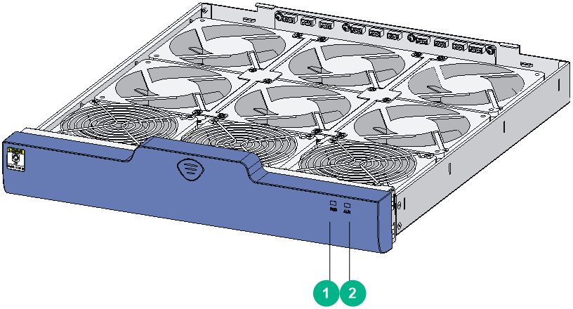
Table3-25 Fan tray LED description
|
LED |
Status |
Description |
|
|
(green) |
RUN |
Off |
The system is powered off or the fan tray is faulty. |
|
Steady on |
The fan tray is operating correctly. |
||
|
(red) |
ALM |
Off |
The fan tray is operating correctly. |
|
Steady on |
The fan tray is faulty. |
||
