- Table of Contents
- Related Documents
-
| Title | Size | Download |
|---|---|---|
| 02-Removable Components | 2.21 MB |
Flexible interface platform modules
Service aggregation platform modules
Hardware compatibility matrixes
MPU and Comware compatibility matrix
Service module and MPU compatibility matrix
Interface module and Comware compatibility matrix
Network port lightning protector
2 Removable components
MPUs
The RPE-X1, RSE-X1, RPE-X3, RPE-X5, RPE-X5E, MCP-X1, and MCP-X2 MPUs are available for the router. You can select them as needed.
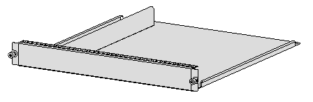
If you order an RPE-X1, RPE-X3, RPE-X5, or RPE-X5E MPU, you must also order a compatible carrier. For the MPU carrier installation procedure, see H3C SR6616 Routers Installation Guide.
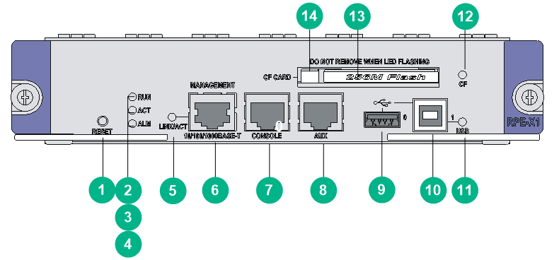
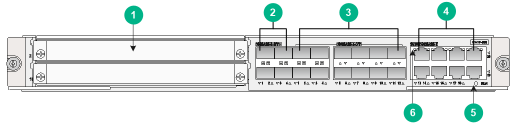
RPE-X1
Figure2-1 RPE-X1 MPU
|
(1) Reset button (RESET) |
(2) RUN LED |
|
(3) Active/Standby LED (ACT) |
(4) Alarm LED (ALM) |
|
(5) LINK/ACT LED for the Ethernet management port |
(6) Management Ethernet port (MANAGEMENT) |
|
(7) Console port (CONSOLE) |
(8) AUX port (AUX) |
|
(9) Host-mode USB port 0 (0) |
(10) Device-mode USB port 1 (1) |
|
(11) USB 1 LED |
(12) CF card LED |
|
(13) CF card |
(14) CF card button |
Table2-1 RPE-X1 specifications
|
Item |
Specification |
|
Flash |
4 MB |
|
Memory type and size |
· Default—One 1-GB DDR2 SDRAM · Maximum—Two 1-GB DDR2 SDRAMs |
|
NVRAM |
128 KB |
|
Console port |
1 9600 bps (default) to 115200 bps |
|
AUX port |
1 9600 bps (default) to 115200 bps |
|
Management Ethernet port |
1 (10Base-T/100Base-TX/1000Base-T) |
|
CF card |
· 256 MB by default for the built-in CF card · 256 MB, 512 MB, or 1 GB for an optional external CF card (CF cards less than 256 MB are not supported) |
|
USB ports |
2 (USB 0: Type A connector, operating in the host mode; USB 1: Type B connector, operating in the device mode) |
|
Dimensions (H × W × D) |
40 × 199 × 282 mm (1.57 × 7.83 × 11.10 in) |
|
Power consumption |
37 W |
|
Reset button |
1 |
|
Hot swapping |
Supported |
|
|
NOTE: · Flash stores the boot file—the BootWare program. · The memory stores the data during system operation and caching the data during data forwarding. · The non-volatile random access memory (NVRAM) stores the exception information of the system during operation. · A CF card stores programs and configuration files of the router. |
RPE-X3
Figure2-2 RPE-X3 MPU

|
(1) USB port |
(2) Management Ethernet port (MANAGEMENT)RUN LED |
|
(3) MPU status LEDs |
(4) Reset button (RESET) |
|
(5) USB console port |
(6) Console port (CONSOLE) |
Table2-2 RPE-X3 specifications
|
Item |
Specification |
|
Flash |
8 MB |
|
Memory type and size |
· Default—One 1-GB DDR2 SDRAM · Maximum—Two 1-GB DDR2 SDRAMs |
|
NVRAM |
128 KB |
|
Console port |
1 9600 bps (default) to 115200 bps Supports switching to AUX port |
|
USB console port |
1 |
|
Management Ethernet port |
1 (10Base-T/100Base-TX/1000Base-T) |
|
USB port |
1 Host mode, type A connector |
|
Reset button |
1 |
|
Hot swapping |
Supported |
|
|
NOTE: · SDRAM stores running configuration and buffers data during data forwarding. · Non-volatile random access memory (NVRAM) stores system exception logs. |
RPE-X5
|
|
CAUTION: If you connect a large-sized USB drive directly to the RPE-X5 MPU, the right ejector lever of the MPU might be damaged. You must use a USB extension cable to connect a large-sized USB drive to the USB port on the MPU. |
Figure2-3 RPE-X5 MPU

|
(1) USB port |
(2) Console/AUX port |
|
(3) Management Ethernet port (MANAGEMENT) |
(4) Management Ethernet port LED |
|
(5) MPU status LEDs |
|
Table2-3 RPE-X5 specifications
|
Item |
Specification |
|
Flash |
4 GB |
|
Memory type and size |
DDR4 SDRAM Default: 4 GB |
|
Console/AUX port |
1, 9600 bps (default) to 115200 bps |
|
Management Ethernet port |
1 (10Base-T/100Base-TX/1000Base-T) |
|
USB port |
1 USB 3.0 port (Host mode, Type A connector) |
|
Hot swapping |
Supported |
|
|
NOTE: SDRAM stores running configuration and buffers data during data forwarding. |
RPE-X5E
|
|
CAUTION: If you connect a large-sized USB drive directly to the RPE-X5E MPU, the right ejector lever of the MPU might be damaged. You must use a USB extension cable to connect a large-sized USB drive to the USB port on the MPU. |
|
|
NOTE: The Ethernet fiber ports SFP+0 and SFP+1 on the RPE-X5E MPU are only used for virtual machine services and do not support Layer 2 or Layer 3 forwarding. For information about how to use these two fiber ports, see H3C SR6600 Router Series VM Deployment Guide. |
Figure2-4 RPE-X5E MPU

|
(1) 10GBASE-R-SFP+ port (SFP+1) |
(2) Console/AUX port |
|
(3) Management Ethernet port (MANAGEMENT) |
(4) Management Ethernet port LED |
|
(5) 10GBASE-R-SFP+ port (SFP+0) |
(6) USB port |
|
(7) MPU status LEDs |
(8) Power button |
Table2-4 RPE-X5E specifications
|
Item |
Specification |
|
Flash |
64 GB |
|
Memory type and size |
DDR4 SDRAM Default: 32 GB |
|
Built-in drive |
512 GB mSATA SSD (optional) NOTE: The RPE-X5E does not support SSC-enabled mSATA drives. |
|
Console/AUX port |
1, 9600 bps (default) to 115200 bps |
|
Management Ethernet port |
1 (10Base-T/100Base-TX/1000Base-T) |
|
10GBASE-R-SFP+ port |
2 |
|
USB port |
1 USB 3.0 port (Host mode, Type A connector) |
|
Power button |
1 |
|
Hot swapping |
Supported |
|
|
NOTE: SDRAM stores running configuration and buffers data during data forwarding. |
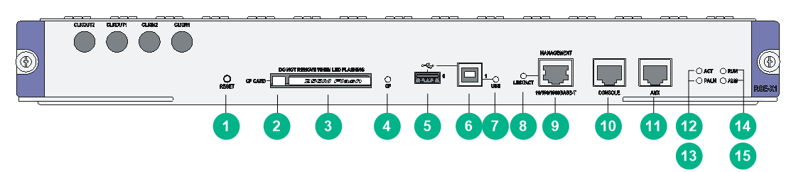
RSE-X1
Figure2-5 RSE-X1 MPU
|
(1) Reset button (RESET) |
(2) CF card button |
|
(3) CF card |
(4) CF card LED |
|
(5) Host-mode USB port 0 (0) |
(6) Device-mode USB port 1 (1) |
|
(7) USB 1 LED |
(8) LINK/ACT LED for the Ethernet management port |
|
(9) Management Ethernet port (MANAGEMENT) |
(10) Console port (CONSOLE) |
|
(11) AUX port (AUX) |
(12) Active/Standby LED (ACT) |
|
(13) Power alarm LED (PALM) |
(14) RUN LED |
|
(15) System alarm LED (ALM) |
|
Table2-5 RSE-X1 specifications
|
Item |
Specification |
|
Flash |
4 MB |
|
Memory type and size |
· Default—Two 1-GB DDR2 SDRAMs · Maximum—Two 2-GB DDR2 SDRAMs |
|
NVRAM |
128 KB |
|
Console port |
1 9600 bps (default) to 115200 bps |
|
AUX port |
1 9600 bps (default) to 115200 bps |
|
Management Ethernet port |
1 (10Base-T/100Base-TX/1000Base-T) |
|
CF card |
· 256 MB by default for the built-in CF card · 256 MB, 512 MB, or 1 GB for an optional external CF card (CF cards less than 256 MB are not supported) |
|
USB ports |
2 (USB 0: Type A connector, operating in the host mode; USB 1: Type B connector, operating in the device mode) |
|
Reset button |
1 |
|
Dimensions (H × W × D) |
45 × 399 × 412 mm (1.77 × 15.71 × 16.22 in) |
|
Power consumption |
75 W |
|
Hot swapping |
Supported |
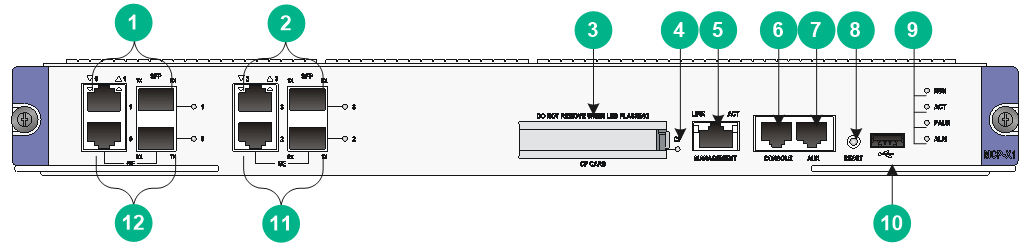
MCP-X1/X2
Figure2-6 MCP-X1
|
(1) Combo interface 1 |
(2) Combo interface 3 |
|
(3) CF card slot (CF CARD) |
(4) CF card LED (CF) |
|
(5) Management Ethernet port (MANAGEMENT) |
(6) Console port (CONSOLE) |
|
(7) AUX port (AUX) |
(8) Reset button (RESET) |
|
(9) MCP-X1 status LED |
(10) USB port |
|
(11) Combo interface 2 |
(12) Combo interface 0 |
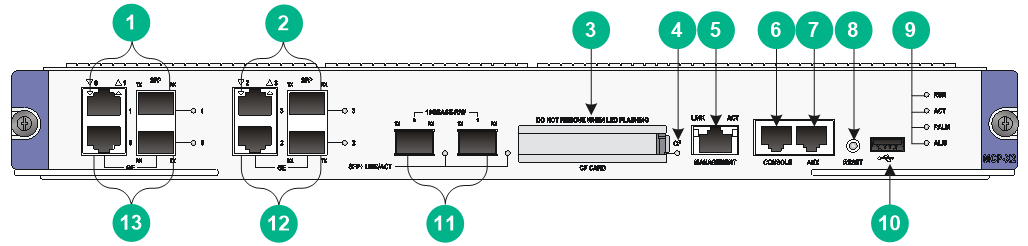
Figure2-7 MCP-X2
|
(1) Combo interface 1 |
(2) Combo interface 3 |
|
(3) CF card slot (CF CARD) |
(4) CF card LED (CF) |
|
(5) Management Ethernet port (MANAGEMENT) |
(6) Console port (CONSOLE) |
|
(7) AUX port (AUX) |
(8) Reset button (RESET) |
|
(9) MCP-X2 status LED |
(10) USB port |
|
(11) 10 Gbps Ethernet port |
(12) Combo interface 2 |
|
(13) Combo interface 0 |
|
Table2-6 MCP specifications
|
Item |
Specification |
|
|
Flash |
8 MB |
|
|
Memory type and size |
DDR3 SDRAM |
|
|
Memory size |
· MCP-X1 · Default—One 2-GB DDR3 SDRAM · Maximum—Two 2-GB DDR3 SDRAMs · MCP-X2 · Default—Two 2-GB DDR3 SDRAMs · Maximum—Two 2-GB DDR3 SDRAMs |
|
|
NVRAM |
128 KB |
|
|
Combo interfaces |
4 |
|
|
Copper ports (automatic MDI/MDI-X) |
10 Mbps, half/full-duplex |
|
|
100 Mbps, half/full-duplex |
||
|
1000 Mbps, full-duplex |
||
|
Fiber ports |
1000 Mbps, full-duplex |
|
|
10 Gbps Ethernet ports |
· MCP-X1—None · MCP-X2—2 |
|
|
Console port |
1 9600 bps (default) to 115200 bps |
|
|
AUX port |
1 9600 bps (default) to 115200 bps |
|
|
Management Ethernet port |
1 (10Base-T/100Base-TX/1000Base-T) |
|
|
CF card |
· 1 GB by default for the built-in CF card · 256 MB, 512 MB, or 1 GB for an optional external CF card (CF cards less than 256 MB are not supported) |
|
|
USB port |
1 (USB 0: Type A connector, operating in the host mode) |
|
|
Reset button |
1 |
|
|
Dimensions (H × W × D) |
45 × 399 × 412 mm (1.77 × 15.71 × 16.22 in) |
|
|
Power consumption |
53 W |
|
|
Hot swapping |
Supported |
|
Components
CF card
|
|
CAUTION: Use CF cards provided by H3C only. The router might be incompatible with other CF cards. |
A compact flash (CF) card stores logs, host files, and configuration files.
The router is equipped with a built-in CF card, which is identified with cfa0. In addition, the router provides an external CF card slot to expand the storage space. A CF card inserted into the external CF card slot is identified with cfb0.
The CF cards supported by the router are available in the following sizes:
· 256 MB
· 512 MB
· 1 GB
CF cards smaller than 256 MB are not supported.
Console port
The router provides an RS232 asynchronous serial console port that can be connected to a computer for system debugging, configuration, maintenance, management, and host software loading.
Table2-7 Console port specifications
|
Item |
Specification |
|
Connector |
RJ-45 |
|
Standard compliant |
Asynchronous EIA/TIA-232 |
|
Baud rate |
9600 bps (default) to 115200 bps |
|
Transmission distance |
≤ 15 m (49.21 ft) |
|
Services |
· Provides connection to an ASCII terminal · Provides connection to the serial port of a local PC to run the terminal emulation program · Command line interface (CLI) |
USB console port
You can connect a configuration terminal to the USB console port if the configuration terminal has a USB port but does not have a serial port. On the configuration terminal, you must install a USB device driver.
Table2-8 USB console port specifications
|
Item |
Description |
|
Connector type |
USB Type AB |
|
Interface standard |
USB 2.0, full speed |
|
Baud rate |
User configurable (default: 9600 bps, maximum: 115200 bps) |
|
Purposes |
· Connects to a character terminal. · Provides a connection to a local configuration terminal that has a USB port but does not have a serial port. |
AUX port
The AUX port is an RS-232 asynchronous serial port used for remote configuration or dialup backup. You must connect the local modem to the remote modem through PSTN and then to the remote device for remote system debugging, configuration, maintenance, and management. In the event that the console port fails, the AUX port can be connected to a terminal as a backup port of the console port. For more information about how to use the AUX port, see H3C SR6616 Routers Installation Guide.
Table2-9 AUX port specifications
|
Item |
Specification |
|
Connector |
RJ-45 |
|
Standard compliant |
Asynchronous EIA/TIA-232 |
|
Baud rate |
9600 bps (default) to 115200 bps |
|
Services |
Connects the serial port of a remote PC through a pair of modems to establish a dial-up connection with the PC |
|
|
NOTE: The dialup function for an AUX port is supported only on Comware 5. For MPU and Comware compatibility, see "MPU and Comware compatibility matrix." |
Management Ethernet port
The management Ethernet port is a 10Base-T/100Base-TX/1000Base-T RJ-45 port. It allows you to upgrade software and manage the router through a network management server without using any service interface of the router. The management Ethernet port is used only for managing the router and it has no service processing capabilities such as data forwarding.
Table2-10 Management Ethernet port specifications
|
Item |
Specification |
|
Connector |
RJ-45 |
|
Interface type |
Automatic MDI/MDI-X |
|
Number of interfaces |
1 |
|
Frame format |
Ethernet_II Ethernet_SNAP |
|
Interface speed and duplex mode |
10 Mbps, half/full-duplex 100 Mbps, half/full-duplex 1000 Mbps, full-duplex |
|
Interface cable and maximum transmission distance |
Category-5 twisted pair with a maximum transmission distance of 100 m (328.08 ft) |
|
|
NOTE: The media dependent interface (MDI) standard is typically used on the Ethernet port of network adapters. The media dependent interface crossover (MDI-X) standard is typically used on hubs or LAN switches. |
Combo interface
The MCP provides four combo interfaces.
Table2-11 Copper Ethernet port specifications
|
Item |
Specification |
|
Connector |
RJ-45 |
|
Interface type |
Automatic MDI/MDI-X |
|
Frame format |
Ethernet_II Ethernet_SNAP |
|
Interface speed and duplex mode |
10 Mbps, half/full-duplex 100 Mbps, half/full-duplex 1000 Mbps, full-duplex |
|
|
NOTE: · The media dependent interface (MDI) standard is typically used on the Ethernet port of network adapters. The media dependent interface crossover (MDI-X) standard is typically used on hubs or LAN switches. · For a combo interface, you can use either the copper port or the fiber port. To switch between the copper and fiber ports, use the combo enable { copper | fiber } command in interface view. |
Table2-12 Fiber Ethernet port specifications
|
Item |
Specification |
|
Connector type |
LC |
|
Transceiver module type |
SFP |
|
Interface standards |
802.3, 802.3u, and 802.3ab |
|
Operating mode |
1000 Mbps, full duplex |
10 Gbps Ethernet port
The MCP-X2 provides two 10 Gbps Ethernet ports. 10 Gbps SFP+ ports do not support 1000 Mbps transceiver modules.
Table2-13 10 Gbps Ethernet port specifications
|
Item |
Specification |
|
Protocol |
802.3ae |
|
Connector type |
LC |
|
Transceiver module type |
SFP+ |
|
Physical layer |
10GBASE-R/W |
|
Transmission rate |
· LAN PHY—10.3125 Gbps · WAN PHY—9.95328 Gbps |
10GBASE-R-SFP+ port
|
Item |
Specification |
|
Connector type |
LC |
|
Transceiver module type |
SFP+ |
|
Interface standards |
802.3ae |
|
Operating mode |
10 Gbps, full duplex |
Reset button
|
|
CAUTION: · If you perform no save operation before resetting the router, the current system configuration will be lost. · Never press the reset (RESET) button when the RUN LED is flashing fast or when the router is accessing the CF card or a USB storage device. Otherwise, the file system of the router might be damaged. |
To reset the current MPU, press the reset button.
· If you press the reset button when only one MPU is equipped, the whole system will be reset.
· To perform an active/standby switchover when two MPUs are equipped, press the reset button on the active MPU. The system automatically switches the services to the standby MPU, without interrupting the ongoing services.
· If you press the reset button on the standby MPU when two MPUs are equipped, the standby MPU will be reset but the system operation will not be affected.
The RUN LED goes off when the MPU is reset, flashes fast (at 8 Hz) when BootWare is running, and flashes slowly (at 1 Hz) after the system is booted and operates correctly.
Power button
|
|
WARNING! The device might still have power after you press the power button. Do not reboot the RPE-X5E MPU or remove power cords from the RPE-X5E MPU until the power button/LED goes off. |
|
|
CAUTION: · Forced power-off might cause data loss in virtual machines. Please use it with caution. · Avoid accidentally pressing the power button when the device is operating. Doing so will power off the device system and cause service interruption. · If a virtual machine cannot be shut down gracefully, log in to it, terminate the running processes, and then shut down it. |
The power button is used to power on or power off the Comware system and virtual machines created on the Comware system.
To gracefully shut down the Comware system when the device is operating, press and hold the power button for 0.5 to 3 seconds. To forcibly shut down the Comware system, press and hold the power button for more than 3 seconds.
By default, pressing the power button on a powered-off device starts the Comware system but not the virtual machines. You can use the autostart command to configure the virtual machines to be started together with the Comware system.
Typically, you can use the reboot command to reboot the RPE-X5E MPU. However, if the RPE-X5E MPU is powered off by pressing the power button, you need to press the power button to turn it on and then execute the reboot command.
Switching fabric modules
The SR6616 router supports switching fabric modules only when it is installed with the RPE-X3/RPE-X5/RPE-X5E MPU.
SFE-L1
Front panel
Figure2-8 SFE-L1 front panel
|
(1) Captive screw |
(2) Ejector lever |
|
(3) Switching fabric module status LED (RUN) |
|
Technical specifications
Table2-14 SFE-L1 specifications
|
Item |
Specification |
|
Memory type and size |
DDR2 SDRAM 2 GB |
|
NVRAM |
128 KB |
|
Hot swapping |
Supported |
|
Quantity |
8 |
|
Compatible device models |
All SR6600 routers except for the SR6616-DS |
SFE-L2
Front panel
Figure2-9 SFE-L2 front panel
|
(1) Captive screw |
(2) Switching fabric module status LED (RUN) |
|
(3) Ejector lever |
|
Technical specifications
Table2-15 SFE-L2 specifications
|
Item |
Specification |
|
Memory type and size |
DDR2 SDRAM, 128 MB |
|
NVRAM |
128 KB |
|
Hot swapping |
Supported |
|
Compatible device models |
SR6616-DS |
Flexible interface platform modules
|
|
IMPORTANT: Use transceiver modules for the flexible interface platform modules (FIPs) provided by H3C only. The router might be incompatible with transceiver modules from other vendors. The system generates an alarm when a transceiver module from another vendor is installed. |
|
|
NOTE: The router does not support the FIP-600 in ESS 7821P09 or later. |
Each combo interface on the FIPs has a fiber port and a copper port. Only one port is activated at a time. By default, the fiber port is activated. To activate a port, use the combo enable { copper | fiber } command in interface view. For more information about the combo enable { copper | fiber } command, see H3C SR6600/SR6600-X Routers Interface Command Reference(V7).
A FIP module is a processing engine and you can install different interface modules on a FIP to support different network services as needed. This section describes the FIP modules available for the H3C SR6616 router.
FIP-10
The FIP-10 supports only MIMs, and you can plug at most four MIMs into a FIP.
Front panel
Figure2-10 FIP-10 front panel
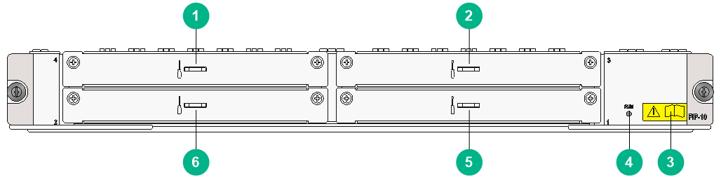
|
(1) Slot 4 |
(2) Slot 3 |
(3) OPEN BOOK mark |
|
(4) Status LED (RUN) |
(5) Slot 1 |
(6) Slot 2 |
The OPEN BOOK mark indicates that the operator must read the following document before working with the FIP:
Table2-16 References for FIP operations
|
Operation |
Reference |
|
Install and remove the FIP |
H3C SR6616 Router Installation Guide |
|
Install and remove MIMs |
|
|
Connect network cables |
|
|
Connect optical fibers |
Technical specifications
|
Item |
Specification |
|
HIM |
Not supported |
|
MIM |
4 MIMs supported at the same time |
|
MIC |
Not supported |
|
Hot-swapping |
Supported |
|
Slot |
Four |
FIP-20
You can plug up to two HIMs or two MIMs into the FIP-20. The FIP-20 also supports intermix of a HIM and a MIM.
Front panel
Figure2-11 FIP-20 front panel
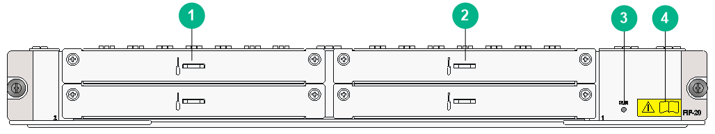
|
(1) Slot 2 |
(2) Slot 1 |
(3) Status LED |
|
(4) OPEN BOOK mark |
|
|
The OPEN BOOK mark indicates that the operator must read the following document before working with the FIP:
Table2-17 References for FIP operations
|
Operation |
Reference |
|
Install and remove the FIP |
H3C SR6616 Router Installation Guide |
|
Install and remove interface modules |
|
|
Connect network cables |
|
|
Connect optical fibers |
Technical specifications
|
Item |
Specification |
|
HIM |
2 HIMs supported |
|
MIM |
2 MIMs supported |
|
MIC |
Not supported |
|
Hot swapping |
Supported |
|
Interface module slot |
2 |
FIP-110
You can plug up to four MIMs into the FIP-110 to provide high-density narrowband aggregation and protect the investment in the MIMs for MSR routers.
Front panel
Figure2-12 FIP-110 front panel

|
(1) Slot 4 |
(2) Slot 3 |
(3) Combo interface 1 |
|
(4) Combo interface 0 |
(5) Slot 1 |
(6) Slot 2 |
|
(7) OPEN BOOK mark |
|
|
The OPEN BOOK mark indicates that the operator must read the following document before working with the FIP:
Table2-18 References for FIP operations
|
Operation |
Reference |
|
Install and remove the FIP |
H3C SR6616 Router Installation Guide |
|
Install and remove MIMs |
|
|
Connect network cables |
|
|
Connect optical fibers |
Technical specifications
|
Item |
Specification |
|
|
Flash |
4 MB |
|
|
Memory type and size |
· Default—Two 1-GB DDR2 SDRAMs · Maximum—Two 2-GB DDR2 SDRAMs |
|
|
NVRAM |
128 KB |
|
|
Combo interfaces |
2 |
|
|
2 copper ports (automatic MDI/MDIX) |
10 Mbps, half/full-duplex |
|
|
100 Mbps, half/full-duplex |
||
|
1000 Mbps, full-duplex |
||
|
2 fiber ports |
1000 Mbps, full-duplex |
|
|
HIM |
Not supported |
|
|
MIM |
4 MIMs supported at the same time |
|
|
MIC |
Not supported |
|
|
Hardware encryption |
Supported |
|
|
Power consumption |
75 W |
|
|
Hot-swapping |
Supported |
|
Combo interface specifications
Table2-19 FIP-110 copper Ethernet port specifications
|
Item |
Specification |
|
|
Connector |
RJ-45 |
|
|
Interface type |
Autosensing |
|
|
Supported frame format |
Ethernet_II Ethernet_SNAP |
|
|
Interface speed and duplex mode |
10 Mbps |
Half/full duplex, auto-negotiation |
|
100 Mbps |
Half/full duplex, auto-negotiation |
|
|
1000 Mbps |
Full duplex, auto-negotiation |
|
Table2-20 FIP-110 fiber Ethernet port specifications
|
Item |
Specification |
|
Connector |
LC |
|
Transceiver module type |
SFP |
|
Interface standards |
802.3, 802.3u, and 802.3ab |
|
Duplex mode |
1000 Mbps, full duplex |
FIP-210
You can plug up to two HIMs into the FIP-210 to provide high-speed service processing or plug up to two MIMs into the FIP to provide high-density narrowband aggregation. The FIP-210 also supports the mix of a HIM and a MIM.
Front panel
Figure2-13 FIP-210 front panel
|
(1) Combo interface 1 |
(2) Combo interface 0 |
(3) Slot 1 |
|
(4) Slot 2 |
(5) OPEN BOOK mark |
|
The OPEN BOOK mark indicates that the operator must read the following document before working with the FIP:
Table2-21 References for FIP operations
|
Operation |
Reference |
|
Install and remove the FIP |
H3C SR6616 Router Installation Guide |
|
Install and remove MIMs |
|
|
Connect network cables |
|
|
Connect optical fibers |
Technical specifications
|
Item |
Specification |
|
|
Flash |
4 MB |
|
|
Memory type and size |
· Default—Two 1-GB DDR2 SDRAMs · Maximum—Two 2-GB DDR2 SDRAMs |
|
|
NVRAM |
128 KB |
|
|
Combo interfaces |
2 |
|
|
2 copper ports (automatic MDI/MDIX) |
10 Mbps, half/full-duplex |
|
|
100 Mbps, half/full-duplex |
||
|
1000 Mbps, full-duplex |
||
|
2 fiber ports |
1000 Mbps, full-duplex |
|
|
HIM |
2 HIMs supported |
|
|
MIM |
2 MIMs supported |
|
|
MIC |
Not supported |
|
|
Hardware encryption |
Supported |
|
|
Hot swapping |
Supported |
|
Combo interface specifications
Specifications of combo interfaces on the FIP-210 and the FIP-110 are the same. For more information, see Table2-19 and Table2-20.
FIP-240
The FIP-240 provides two combo interfaces. It supports HIMs, MIMs, or a mix of HIMs and MIMs.
Front panel
Figure2-14 FIP-240 front panel
|
(1) Slot 4 |
(2) Slot 3 |
|
(3) Combo interface 1 |
(4) Combo interface 0 |
|
(5) Slot 1 |
(6) Slot 2 |
Technical specifications
|
Item |
Specification |
|
|
Flash |
8 MB |
|
|
Memory type and size |
· Default—One 2-GB DDR3 SDRAM · Maximum—Two 2-GB DDR3 SDRAMs |
|
|
NVRAM |
128 KB |
|
|
Combo interface |
2 |
|
|
2 copper ports (MDI/MDIX autosensing) |
10 Mbps, half/full-duplex |
|
|
100 Mbps, half/full-duplex |
||
|
1000 Mbps, full-duplex |
||
|
2 fiber ports |
1000 Mbps, full-duplex |
|
|
MIM |
4 supported |
|
|
HIM |
2 full-height or 4 half-height HIMs supported NOTE: Half-height HIMs include the following models: · HIM-4G4P. · HIM-TS8P. · HIM-8GBP-V2. · HIM-8GBP-V3. · HIM-4GBP-V3. · HIM-8GBE-V3. · HIM-4GBE-V3. |
|
|
MIC |
Not supported |
|
|
Hardware encryption |
Supported |
|
|
Hot swapping |
Supported |
|
Combo interface specifications
Specifications of combo interfaces on the FIP-240 and the FIP-110 are the same. For more information, see Table2-19 and Table2-20.
FIP-260
A FIP-260 provides four MIC-X interface module slots.
Front panel
Figure2-15 FIP-260 front panel
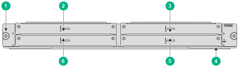
|
(1) Captive screw |
(2) Slot 4 |
|
(3) Slot 3 |
(4) Ejector lever |
|
(5) Slot 1 |
(6) Slot 2 |
Technical specifications
|
Item |
Specification |
|
Memory type and size |
4GB DDR4 |
|
Drive |
(Optional) 512 GB mSATA SSD The mSATA hard disk with SSC enabled is not supported on the FIP-260. |
|
MIM |
Not supported |
|
HIM |
Not supported |
|
MIC |
Not supported |
|
MIC-X |
A maximum of 4 |
|
Hardware encryption |
Supported |
|
Hot swapping |
Supported |
FIP-300
The FIP-300 provides 12 combo interfaces. It supports HIMs, MIMs, or a mix of HIMs and MIMs.
Front panel
Figure2-16 FIP-300 front panel
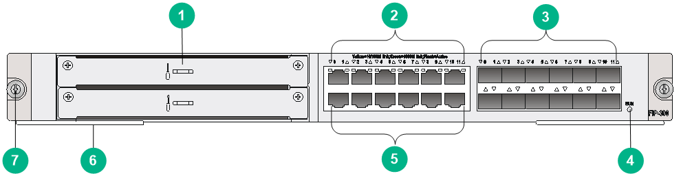
|
(1) HIM/MIM slot |
(2) GE0 through GE11 copper port status LEDs |
|
(3) GE0 through GE11 fiber ports |
(4) RUN LED |
|
(5) GE0 through GE11 copper ports |
(6) Ejector lever |
|
(7) Captive screw |
|
Technical specifications
|
Item |
Specification |
|
|
Flash |
8 MB |
|
|
Memory type and size |
· Default—Two 2-GB DDR3 SDRAMs · Maximum—Two 2-GB DDR3 SDRAMs The SDRAMs must be used in pairs and must be the same size. |
|
|
NVRAM |
128 KB |
|
|
Combo interface |
12 |
|
|
Copper ports (MDI/MDIX autosensing) |
10 Mbps, half/full-duplex |
|
|
100 Mbps, half/full-duplex |
||
|
1000 Mbps, full-duplex |
||
|
Fiber ports |
1000 Mbps, full-duplex |
|
|
HIM |
1 |
|
|
MIM |
1 |
|
|
MIC |
Not supported |
|
|
Hardware encryption |
Supported |
|
|
Hot swapping |
Supported |
|
Combo interface specifications
Specifications of combo interfaces on the FIP-300 and the FIP-110 are the same. For more information, see Table2-19 and Table2-20.
FIP-310
The FIP-310 provides four combo interfaces and two SFP+ ports. It supports HIMs, MIMs, or a mix of HIMs and MIMs.
Front panel
Figure2-17 FIP-310 front panel
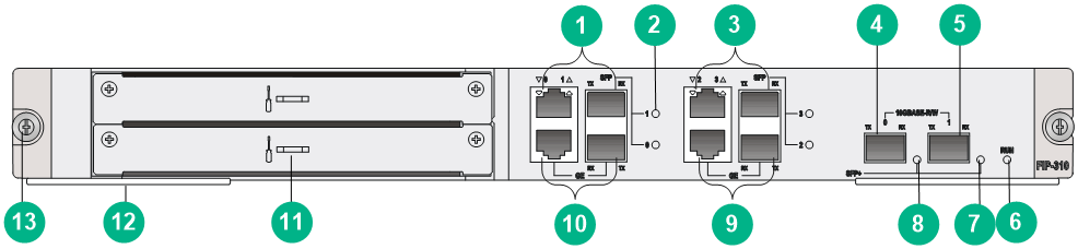
|
(1) Combo interface 1 |
(2) Combo interface status LED |
(3) Combo interface 3 |
|
(4) SFP+ port 0 |
(5) SFP+ port 1 |
(6) RUN LED |
|
(7) SFP+ port 1 status LED |
(8) SFP+ port 0 status LED |
(9) Combo interface 2 |
|
(10) Combo interface 0 |
(11) HIM/MIM slot |
(12) Ejector lever |
|
(13) Captive screw |
|
|
Technical specifications
|
Item |
Specification |
|
|
Flash |
8 MB |
|
|
Memory type and size |
· Default—Two 2-GB DDR3 SDRAMs · Maximum—Two 2-GB DDR3 SDRAMs The SDRAMs must be used in pairs and must be the same size. They must be inserted in slot 1 or slot 3. These two slots are located near the backplane connectors on the FIP module. |
|
|
NVRAM |
128 KB |
|
|
Combo interfaces |
2 |
|
|
2 copper ports (automatic MDI/MDIX) |
10 Mbps, half/full-duplex |
|
|
100 Mbps, half/full-duplex |
||
|
1000 Mbps, full-duplex |
||
|
2 fiber ports |
1000 Mbps, full-duplex |
|
|
10G Ethernet port |
2 |
|
|
HIM |
1 |
|
|
MIM |
1 |
|
|
MIC |
Not supported |
|
|
Hardware encryption |
Supported |
|
|
Hot-swapping |
Supported |
|
Combo interface specifications
Specifications of combo interfaces on the FIP-310 and the FIP-110 are the same. For more information, see Table2-19 and Table2-20.
10GE port specifications
Table2-22 FIP-310 10GE port specifications
|
Item |
Specification |
|
Connector |
LC |
|
Transceiver module type |
SFP+ |
|
Interface standards |
802.3ae |
|
Duplex mode |
10 Gbps, full duplex |
FIP-380
A FIP-380 delivers high-speed service processing capability. It provides two 10GBASE-R-SFP+ ports, fourteen 1000BASE-X-SFP ports, and eight 100/1000BASE-T copper ports. It supports MIC-X interface modules.
Front panel
Figure2-18 FIP-380 front panel
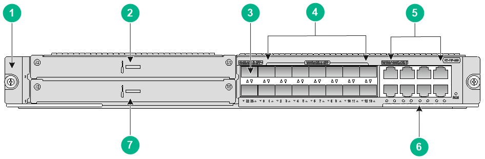
|
(1) Captive screw |
(2) Slot 2 |
|
(3) 10GBASE-R-SFP+ ports SFP+22 and SFP+23 |
(4) 1000BASE-X-SFP ports SFP0 to SFP13 |
|
(5) 100/1000 BASE-T Ethernet copper ports GE14 to GE21 |
(6) Ejector lever |
|
(7) Slot 1 |
|
Technical specifications
Table2-23 FIP-380 technical specifications
|
Item |
Specification |
|
Memory type and size |
8GB DDR4 |
|
Drive |
(Optional) 512 GB mSATA SSD The mSATA hard disk with SSC enabled is not supported on the FIP-380. |
|
10GBASE-R-SFP+ ports |
2 |
|
1000BASE-X-SFP ports |
14 |
|
100/1000BASE-T ports |
8 |
|
HIM |
Not supported |
|
MIM |
Not supported |
|
MIC |
Not supported |
|
MIC-X |
A maximum of 2 |
|
Hardware encryption |
Supported |
|
Hot swapping |
Supported |
Interface specifications
Table2-24 10GBASE-R-SFP+ port specifications
|
Item |
Specification |
|
Connector |
LC |
|
Transceiver module type |
SFP+ |
|
Interface standards |
802.3ae |
|
Operating mode |
10 Gbps, full duplex |
Table2-25 1000BASE-X-SFP port specifications
|
Item |
Specification |
|
Connector |
LC |
|
Transceiver module type |
SFP |
|
Interface standards |
802.3, 802.3u, and 802.3ab |
|
Operating mode |
1000 Mbps, full duplex |
Table2-26 100/1000BASE-T port specifications
|
Item |
Specification |
|
|
Connector |
RJ-45 |
|
|
Operating mode |
100 Mbps autosensing |
Full duplex, auto-negotiation |
|
1000 Mbps autosensing |
Full duplex, auto-negotiation |
|
FIP-600
The FIP-600 provides four combo interfaces. It supports a maximum of two HIMs.
Front panel
Figure2-19 FIP-600 front panel
|
(1) Combo interface 1 |
(2) Combo interface 0 |
(3) Slot 1 |
|
(4) Slot 2 |
(5) OPEN BOOK mark |
|
Technical specifications
|
Item |
Specification |
|
|
Flash |
8 MB |
|
|
Memory type and size |
· Default—Two 2-GB DDR3 SDRAMs · Maximum—Two 2-GB DDR3 SDRAMs The SDRAMs must be used in pairs and must be the same size. They must be inserted in slot 1 or slot 3. These two slots are located near the backplane connectors on the FIP module. |
|
|
NVRAM |
128 KB |
|
|
Combo interfaces |
2 |
|
|
2 copper ports (automatic MDI/MDIX) |
10 Mbps, half/full-duplex |
|
|
100 Mbps, half/full-duplex |
||
|
1000 Mbps, full-duplex |
||
|
2 fiber ports |
1000 Mbps, full-duplex |
|
|
HIM |
2 |
|
|
MIM |
Not supported |
|
|
MIC |
Not supported |
|
|
Hardware encryption |
Supported |
|
|
Hot-swapping |
Supported |
|
Combo interface specifications
Specifications of combo interfaces on the FIP-600 and the FIP-110 are the same. For more information, see Table2-19 and Table2-20.
FIP-660
A FIP-660 provides four MIC-X interface module slots. When installing a FIP-660, if a service module slot adjacent to the FIP-660 is empty, install an air deflector over the slot. For information about how to install an air deflector, see H3C SR6616 Routers Installation Guide.
Front panel
Figure2-20 FIP-660 front panel
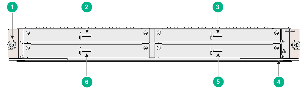
|
(1) Captive screw |
(2) Slot 4 |
|
(3) Slot 3 |
(4) Ejector lever |
|
(5) Slot 1 |
(6) Slot 2 |
Air deflector
Figure2-21 FIP-660 air defelctor
Technical specifications
|
Item |
Specification |
|
Memory type and size |
16GB DDR4 |
|
Drive |
Not supported |
|
MIM |
Not supported |
|
HIM |
Not supported |
|
MIC |
Not supported |
|
MIC-X |
A maximum of 4 |
|
Hardware encryption |
Supported |
|
Hot swapping |
Supported |
FIP-680
The FIP-680 provides 4 SFP+ ports, 12 SFP ports, and 8 copper GE ports. It supports a maximum of two MICs.
Front panel
Figure2-22 FIP-680 front panel
|
(1) Interface module slot |
(2) 10GBASE-R-SFP+ ports (4 in total) |
|
(3) 1000BASE-X-SFP ports (12 in total) |
(4) 10/100/1000BASE-T copper Ethernet ports (8 in total) |
|
(5) Module status LED (RUN) |
(6) 10/100/1000BASE-T copper Ethernet port status LED |
Technical specifications
|
Item |
Specification |
|
Memory type and size |
· Default—Two 4-GB DDR3 SDRAMs · Maximum—Two 4-GB DDR3 SDRAMs The SDRAMs must be used in pairs and must be the same size. |
|
NVRAM |
128 KB |
|
10GE fiber ports (SFP+) |
4 |
|
GE fiber ports (SFP) |
12 |
|
Copper Ethernet ports |
8 10/100/1000M autosensing |
|
HIM |
Not supported |
|
MIM |
Not supported |
|
MIC |
2 |
|
Hardware encryption |
Supported |
|
Hot-swapping |
Supported |
10GE SFP+ port specifications
Table2-27 FIP-680 10GE SFP+ port specifications
|
Item |
Specification |
|
Connector |
LC |
|
Transceiver module type |
SFP+ |
|
Synchronous Ethernet |
Not supported |
|
1588v2.2 |
Not supported |
|
Interface standards |
802.3ae |
|
Duplex mode |
10 Gbps, full duplex |
GE SFP port specifications
Table2-28 FIP-680 GE SFP port specifications
|
Item |
Specification |
|
Connector |
LC |
|
Transceiver module type |
SFP |
|
Synchronous Ethernet |
Not supported |
|
1588v2.2 |
Not supported |
|
Interface standards |
802.3, 802.3u, and 802.3ab |
|
Duplex mode |
1000 Mbps, full duplex |
Copper Ethernet port specifications
Table2-29 FIP-680 copper Ethernet port specifications
|
Item |
Specification |
|
|
Connector |
RJ-45 |
|
|
Interface type |
Autosensing |
|
|
Supported frame format |
Ethernet_II Ethernet_SNAP |
|
|
Interface speed and duplex mode |
10 Mbps |
Half/full duplex, auto-negotiation |
|
100 Mbps |
Half/full duplex, auto-negotiation |
|
|
1000 Mbps |
Full duplex, auto-negotiation |
|
Service aggregation platform modules
|
|
IMPORTANT: Use transceiver modules for the service aggregation platform modules (SAPs) provided by H3C only. The router might be incompatible with transceiver modules from other vendors. The system generates an alarm when a transceiver module from another vendor is installed. |
Each combo interface on the SAPs has a fiber port and a copper port. Only one port is activated at a time. By default, the fiber port is activated. To activate a port, use the combo enable { copper | fiber } command in interface view. For more information about the combo enable { copper | fiber } command, see H3C SR6600/SR6600-X Routers Interface Command Reference(V7).
A SAP module provides network ports for receiving packets from the network and sending packets to the network. This section describes the SAPs available for the H3C SR6616 router.
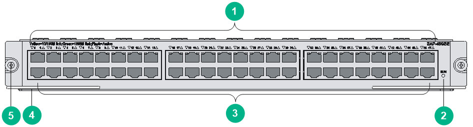
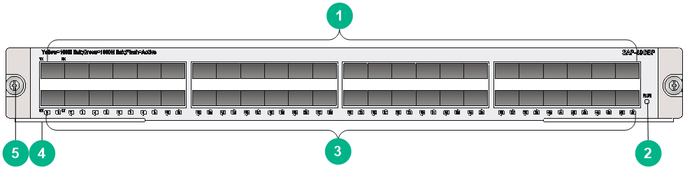
SAP-48GBE
The SAP-48GBE has 48 high-performance RJ-45 ports that can be both routed and switched. One two-color LED is available for each port to indicate their activity and link status. The module also has a RUN LED to indicate the module operating status.
Front panel
Figure2-23 SAP-48GBE front panel
|
(1) LEDs for GE ports 0 to 47 |
(2) SAP module status LED (RUN) |
|
(3) GE ports 0 to 47 |
(4) Ejector levers |
|
(5) Captive screw |
|
Technical specifications
|
Item |
Specification |
|
|
Flash |
4 MB |
|
|
Memory type and size |
· Default—Two 1-GB DDR2 SDRAMs · Maximum—Two 2-GB DDR2 SDRAMs |
|
|
NVRAM |
128 KB |
|
|
Max power consumption |
200 W |
|
|
Connector type |
RJ-45 |
|
|
Number of interfaces |
48 |
|
|
Interface standards |
802.3, 802.3u, and 802.3ab |
|
|
Interface type |
Automatic MDI/MDIX |
|
|
Cable type |
Straight-through/crossover Ethernet cable |
|
|
Transmission distance |
100 m (328.08 ft) |
|
|
Supported frame format |
Ethernet_II Ethernet_SNAP |
|
|
Interface speed and duplex mode |
10 Mbps |
Full/half duplex, auto-negotiation |
|
100 Mbps |
Full/half duplex, auto-negotiation |
|
|
1000 Mbps |
Full duplex, auto-negotiation |
|
SAP-24GBP
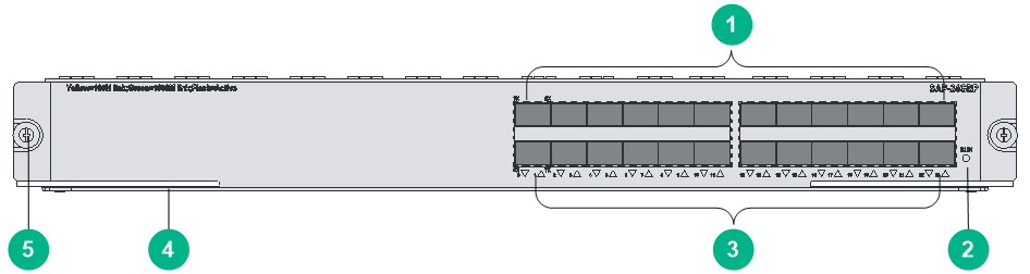
The SAP-24GBP has 24 high-performance fiber SFP ports that can be both routed and switched. One two-color LED is available for each port to indicate their activity and link status. The module also has a RUN LED to indicate the module operating status.
Front panel
Figure2-24 SAP-24GBP front panel
|
(1) SFP ports 0 to 23 |
(2) SAP module status LED (RUN) |
|
(3) LEDs for SFP ports 0 to 23 |
(4) Ejector levers |
|
(5) Captive screw |
|
Technical specifications
|
Item |
Specification |
|
Flash |
4 MB |
|
Memory type and size |
· Default—Two 1-GB DDR2 SDRAMs · Maximum—Two 2-GB DDR2 SDRAMs |
|
NVRAM |
128 KB |
|
Max power consumption |
150 W |
|
Connector type |
SFP |
|
Number of interfaces |
24 |
|
Interface standards |
802.3, 802.3u, and 802.3ab |
|
Supported frame format |
Ethernet_II Ethernet_SNAP |
|
Interface speed |
1000 Mbps (recommended) Full duplex |
Fixed Ethernet port specifications
Specifications of the SAP-24GBP fixed Ethernet ports and the FIP-110 fiber combo ports are the same. For more information, see Table2-20.
SAP-48GBP
The SAP-48GBP has 48 high-performance fiber SFP ports that can be both routed and switched. One two-color LED is available for each port to indicate their activity and link status. The module also has a RUN LED to indicate the module operating status.
Front panel
Figure2-25 SAP-48GBP front panel
|
(1) SFP ports 0 to 47 |
(2) SAP module status LED (RUN) |
|
(3) LEDs for SFP ports 0 to 47 |
(4) Ejector levers |
|
(5) Captive screw |
|
Technical specifications
|
Item |
Specification |
|
Flash |
4 MB |
|
Memory type and size |
· Default—Two 1-GB DDR2 SDRAMs · Maximum—Two 2-GB DDR2 SDRAMs |
|
NVRAM |
128 KB |
|
Max power consumption |
144 W |
|
Connector type |
SFP |
|
Number of interfaces |
48 |
|
Interface standards |
802.3, 802.3u, and 802.3ab |
|
Supported frame format |
Ethernet_II Ethernet_SNAP |
|
Interface speed |
1000 Mbps (recommended) Full duplex |
Fixed Ethernet port specifications
Specifications of the SAP-48GBP fixed Ethernet ports and the FIP-110 fiber combo ports are the same. For more information, see Table2-20.
SAP-20GE2XP
Front panel
Figure2-26 SAP-20GE2XP front panel

|
(1) SFP ports (GE0 to GE15) |
(2) Combo interfaces (GE16 to GE19) |
|
(3) SFP+ port 0 |
(4) SFP+ port 1 |
|
(5) Operating status LED (RUN) |
|
Technical specifications
|
Item |
Specification |
|
Flash |
8 MB. |
|
Memory type and size |
· Default—Two 2-GB DDR3 SDRAMs. · Maximum—Four 2-GB DDR3 SDRAMs. |
|
NVRAM |
128 KB. |
|
SFP ports |
16 × SFP ports, 100/1000 Mbps auto-sensing. |
|
Combo interfaces |
Four. · Copper port—Straight-through/crossover autosensing: ¡ 10/100 Mbps, half/full-duplex. ¡ 1000 Mbps, full-duplex. · Fiber port—1000 Mbps, full-duplex. |
|
10G SFP+ ports |
2. |
|
Hot swapping |
Supported. |
Fixed Ethernet port specifications
Table2-30 SFP port specifications
|
Item |
Specification |
|
Connector type |
LC |
|
Transceiver module type |
SFP |
|
Network synchronization |
Supported |
|
1588v2.2 protocol |
Supported |
|
Interface standards |
802.3, 802.3u, and 802.3ab |
|
Operating mode |
1000 Mbps, full duplex |
Table2-31 Copper combo port specifications
|
Item |
Specification |
|
|
Connector type |
RJ-45 |
|
|
Interface type |
Auto MDI/MDI-X |
|
|
Frame format supported |
· Ethernet_II · Ethernet_SNAP |
|
|
Interface speed and duplex mode |
10 Mbps auto-sensing |
Half/full duplex, auto-negotiation |
|
100 Mbps auto-sensing |
Half/full duplex, auto-negotiation |
|
|
1000 Mbps auto-sensing |
Full duplex, auto-negotiation |
|
For the fiber combo port specifications, see Table2-30.
Table2-32 SFP+ port specifications
|
Item |
Specification |
|
Connector type |
LC |
|
Transceiver module |
SFP+ |
|
Network synchronization |
Supported |
|
1588v2.2 protocol |
Supported |
|
Interface standards |
802.3ae |
|
Operating mode |
10 Gbps, full duplex |
SAP-28GE
Front panel
Figure2-27 SAP-28GE front panel

|
(1) SFP ports (GE0 to GE15) |
(2) Combo interfaces (GE16 to GE27) |
|
(3) Operating status LED (RUN) |
|
Technical specifications
|
Item |
Specification |
|
Flash |
8 MB. |
|
Memory type and size |
· Default—Two 2-GB DDR3 SDRAMs. · Maximum—Four 2-GB DDR3 SDRAMs. |
|
NVRAM |
128 KB. |
|
SFP ports |
16 × SFP ports, 100/1000 Mbps auto-sensing. |
|
Combo interfaces |
12. · Copper port—Straight-through/crossover autosensing: ¡ 10/100 Mbps, half/full-duplex. ¡ 1000 Mbps, full-duplex. · Fiber port—1000 Mbps, full-duplex. |
|
Hot swapping |
Supported. |
Fixed Ethernet port specifications
Table2-33 SFP port specifications
|
Item |
Specification |
|
Connector type |
LC |
|
Transceiver module type |
SFP |
|
Network synchronization |
Supported |
|
1588v2.2 protocol |
Supported |
|
Interface standards |
802.3, 802.3u, and 802.3ab |
|
Operating mode |
1000 Mbps, full duplex |
Table2-34 Copper combo port specifications
|
Item |
Specification |
|
|
Connector type |
RJ-45 |
|
|
Interface type |
Auto MDI/MDI-X |
|
|
Frame format supported |
· Ethernet_II · Ethernet_SNAP |
|
|
Interface speed and duplex mode |
10 Mbps auto-sensing |
Half/full duplex, auto-negotiation |
|
100 Mbps auto-sensing |
Half/full duplex, auto-negotiation |
|
|
1000 Mbps auto-sensing |
Full duplex, auto-negotiation |
|
For the fiber combo port specifications, see Table2-33.
SAP-XP4GE32
Front panel
Figure2-28 SAP-XP4GE32 front panel

|
(1) Captive screw |
(2) 10/100/1000Base-T Ethernet copper ports GE0 to GE11 |
|
(3) Combo interfaces GE12 to GE23 |
|
|
(4) 1000BASE-X-SFP ports SFP24 to SFP31 |
|
|
(5) 10GBASE-R-SFP+ ports SFP+32 to SFP+35 |
|
|
(6) Operating status LED (RUN) |
(7) Ejector lever |
Technical specifications
|
Item |
Specification |
|
Memory type and size |
8GB DDR4 |
|
Built-in hard disk |
(Optional) 512 GB mSATA SSD The mSATA hard disk with SSC enabled is not supported on the SAP-XP4GE32. |
|
Transceiver modules |
8 × 1000BASE-X-SFP ports 4 ×10GBASE-R-SFP+ ports |
|
Ethernet copper ports |
12 × 10/100/1000Base-T Ethernet copper ports |
|
Combo interfaces |
12 |
|
Hot swapping |
Supported. |
Fixed Ethernet port specifications
Table2-35 10/100/1000BASE-T Ethernet copper port specifications
|
Item |
Specification |
|
|
Connector type |
RJ-45 |
|
|
Interface type |
Autosensing |
|
|
Interface speed and duplex mode |
10 Mbps |
Full duplex, auto-negotiation |
|
100 Mbps |
Full duplex, auto-negotiation |
|
|
1000 Mbps |
Full duplex, auto-negotiation |
|
Table2-36 1000BASE-X-SFP port specifications
|
Item |
Specification |
|
Connector type |
LC |
|
Transceiver module type |
SFP |
|
Interface standards |
802.3, 802.3u, and 802.3ab |
|
Operating mode |
1000 Mbps, full duplex |
Table2-37 10GBASE-R-SFP+ port specifications
|
Item |
Specification |
|
Connector type |
LC |
|
Transceiver module type |
SFP+ |
|
Interface standards |
802.3ae |
|
Operating mode |
10 Gbps, full duplex |
For the copper combo port specifications, see Table2-35.
For the fiber combo port specifications, see Table2-36.
Hardware compatibility matrixes
In the compatibility matrices, "√" means "Supported" and "×" means "Not supported."
MPU and Comware compatibility matrix
Table2-1 MPU and Comware compatibility matrix
|
MPU |
Comware 5 |
Comware 7 |
|
RPE-X1 |
√ |
× |
|
RPE-X3 |
× |
√ |
|
RPE-X5 |
× |
√ |
|
RPE-X5E |
× |
√ |
|
RSE-X1 |
√ |
× |
|
MCP-X1 |
√ |
× |
|
MCP-X2 |
√ |
× |
Service module and MPU compatibility matrix
Table2-2 Service module and MPU compatibility matrix
|
Service module |
RPE-X1 |
RPE-X3 |
RPE-X5 |
RPE-X5E |
RSE-X1 |
MCP-X1 |
MCP-X2 |
|
FIP-10 |
× |
× |
× |
× |
× |
√ |
√ |
|
FIP-110 |
√ |
× |
× |
× |
√ |
× |
× |
|
FIP-20 |
× |
× |
× |
× |
× |
√ |
√ |
|
FIP-210 |
√ |
× |
× |
× |
√ |
× |
× |
|
FIP-240 |
√ |
√ |
√ |
√ |
√ |
× |
× |
|
FIP-260 |
× |
√ |
√ |
√ |
× |
× |
× |
|
FIP-300 |
× |
√ |
× |
× |
× |
× |
× |
|
FIP-310 |
× |
√ |
× |
× |
× |
× |
× |
|
FIP-380 |
× |
√ |
√ |
√ |
× |
× |
× |
|
FIP-600 |
× |
√ |
× |
× |
× |
× |
× |
|
FIP-660 |
× |
√ |
√ |
√ |
× |
× |
× |
|
FIP-680 |
× |
√ |
√ |
√ |
× |
× |
× |
|
SAP-48GBE |
× |
× |
× |
× |
√ |
× |
× |
|
SAP-24GBP |
× |
× |
× |
× |
√ |
× |
× |
|
SAP-48GBP |
× |
× |
× |
× |
√ |
× |
× |
|
SAP-20GE2XP |
× |
√ |
× |
× |
× |
× |
× |
|
SAP-28GE |
× |
√ |
× |
× |
× |
× |
× |
|
SAP-XP4GE32 |
× |
√ |
√ |
√ |
× |
× |
× |
|
SPE-FWM-200 |
√ |
× |
× |
× |
√ |
× |
× |
|
SPE-SSL-200 |
√ |
× |
× |
× |
√ |
× |
× |
Interface module and Comware compatibility matrix
Table2-3 Interface module and Comware compatibility matrix
|
Interface module |
Comware 5 |
Comware 7 |
|
SAPs |
||
|
SAP-48GBE |
√ |
× |
|
SAP-24GBP |
√ |
× |
|
SAP-48GBP |
√ |
× |
|
SAP-20GE2XP |
× |
√ |
|
SAP-28GE |
× |
√ |
|
SAP-XP4GE32 |
× |
√ |
|
OAPs |
||
|
SPE-FWM-200 |
√ |
× |
|
SPE-SSL-200 |
√ |
× |
Power supplies
The router supports hot-swappable AC and DC power supplies, but an AC power supply and a DC power supply cannot work together. You can install one power supply or multiple power supplies for redundancy, but the power supplies in use must have the same specifications.
AC power supplies
PSR650-A
Figure2-29 PSR650-A view
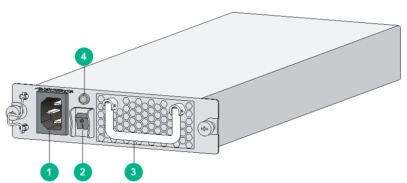
|
(1) AC-input power receptacle |
(2) Power switch |
|
(3) Handle |
(4) Power supply status LED |
Table2-4 PSR650-A specifications
|
Item |
Specification |
|
Model |
PSR650-A |
|
Rated input voltage |
100 VAC to 240 VAC @ 50 or 60 Hz |
|
Maximum input current |
10 A |
|
Maximum power |
650 W |
PSR1200-A
Figure2-30 PSR1200-A view

|
(1) AC-input power receptacle |
(2) Power switch |
|
(3) Handle |
(4) Power supply status LED |
Table2-5 PSR1200-A specifications
|
Item |
Specification |
|
Model |
PSR1200-A |
|
Rated input voltage |
100 VAC to 240 VAC @ 50 or 60 Hz |
|
Maximum input current |
16 A |
|
Maximum power |
1213 W |
DC power supplies
PSR650-D
Figure2-31 PSR650-D view
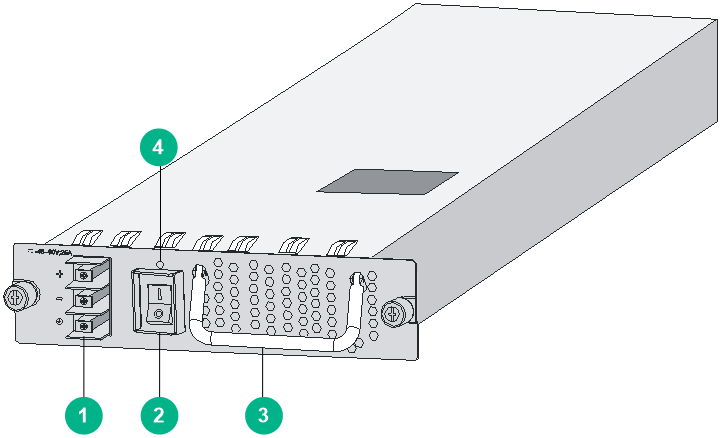
|
(1) DC-input terminal block |
(2) Power switch |
|
(3) Handle |
(4) Power supply status LED |
Table2-6 PSR650-D specifications
|
Item |
Specification |
|
Model |
PSR650-D |
|
Rated input voltage |
–48 VDC to –60 VDC |
|
Maximum input current |
25 A |
|
Maximum power |
650 W |
PSR1200-D
Figure2-32 PSR1200-D view
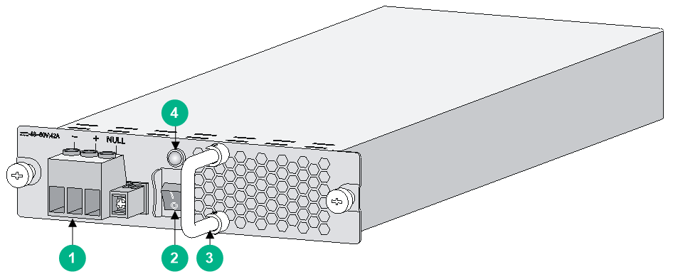
|
(1) Power supply connector |
(2) Power switch |
|
(3) Handle |
(4) Power supply status LED |
Table2-7 PSR1200-D specifications
|
Item |
Specification |
|
Model |
PSR1200-D |
|
Rated input voltage |
–48 VDC to –60 VDC |
|
Maximum input current |
42 A |
|
Maximum power |
1213 W |
Fan tray
Figure2-33 Fan tray
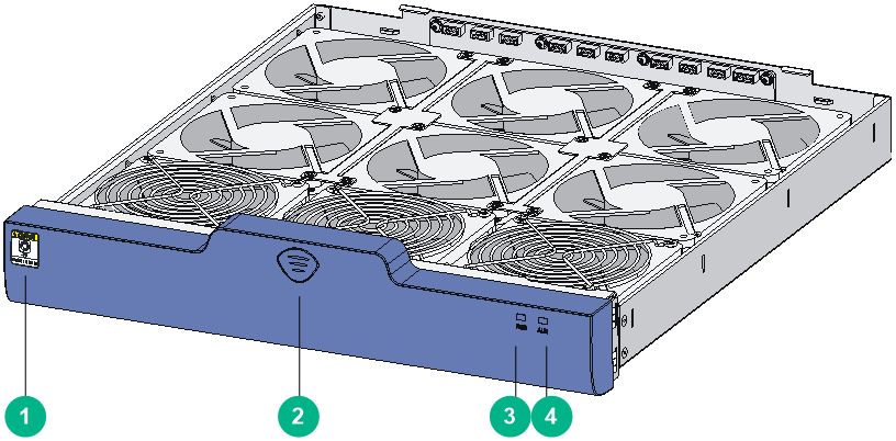
|
(1) Rotating blade hazard label |
(2) Fan tray release button |
|
(3) Fan tray status LED (RUN) |
(4) Alarm LED (ALM) |
Table2-8 Fan tray specifications
|
Item |
Specifications |
|
Fan number |
9 |
|
Dimensions ( H x W x D) |
78.1 x 410.2 ×447.8 mm (3.07 x 16.15 x 17.63 in) |
|
Weight |
5 kg (11.02 lb) |
|
Automatic fan speed adjustment |
Supported |
|
Failsafe |
Supported |
|
Hot swapping |
Supported |
Transceiver modules
For more information about transceiver modules supported by the SR6616 switch, see the H3C SR6600/SR6600-X Routers Interface Module Guide.
Network port lightning protector
Before connecting an outdoor Ethernet cable to an Ethernet port, you can install a lightning protector to protect the router against lightning strikes. The specifications for the lightning protector that can be installed on the router are as follows:
Port protective unit–single port, maximum discharge current (8/20μs waveform): 5 kA, output voltage (10/700μs waveform): core-core < 40 V, core-ground < 600 V.
For information about how to install a network port lightning protector, see H3C SR6616 Routers Installation Guide.
Power strip with lightning protection
If part of the AC power line is routed outdoors, use a power strip with lightning protection to connect the AC power cord of the router to the AC power line to protect the router from being damaged by lightning strikes. You can attach the power strip to the rack, workbench, or wall of equipment room.
The specifications for the power lightning arrester that can be installed on the router are as follows:
Maximum discharge current: 6500 A, protection voltage: 500 VAC to 220 VAC.
For information about how to connect the AC power supply to a power strip with lightning protection, see H3C SR6616 Routers Installation Guide.
Surge protector
Typically, you must connect a surge protector—a transient over-voltage protection—before connecting a signal cable to the router. This can protect electronic devices against surge over-voltage resulting from lightning strikes and other interferences, and minimize impact on the router.
The router supports the following types of surge protectors:
· Voltage-limiting protection parts-signal lightning arrester-maximum discharge current 2.5KA/protection voltage 25V--SMB-75J/SMB-75J-1W-10Mbps.
· Voltage-limiting protection parts-signal lightning arrester-maximum discharge current 2.5KA/protection voltage 25V-BNC-75K/BNC-75K-10MBit/s.
· Voltage-limiting protection parts-signal lightning arrester (U port)-maximum discharge current 3KA/common mode: 400 V/differential mode: 170V-RJ11.
For information about how to install a surge protector, see H3C SR6616 Routers Installation Guide.
