- Table of Contents
- Related Documents
-
| Title | Size | Download |
|---|---|---|
| 03-LEDs | 509.32 KB |
Active/standby state LED (ACTIVE)
PSR650-A/PSR650-D/PSR1200-A/PSR1200-D
PSR650C-12A/PSR650C-12D/PSR1400-A/PSR2500-12AHD/PSR2500-12D
3 LEDs
The MPUs, interface modules, and power modules available for the switch use multiple LEDs to indicate their operating status. The LED type and quantity vary by module model.
Table 3-1 lists the LEDs on the MPUs, interface modules, and power modules.
|
|
NOTE: Unless otherwise specified, the flashing frequency of the LEDs in this section is once per two seconds. |
|
LEDs |
|
· Management Ethernet port LEDs · Power module status LED (PWR) |
|
· PSR320-A · PSR650-A/PSR650-D/PSR1200-A/PSR1200-D · PSR650C-12A/PSR650C-12D/PSR1400-A/PSR2500-12AHD/PSR2500-12D |
MPU LEDs
Multiple MPUs are available for the switch. These MPUs provide different types and numbers of LEDs.
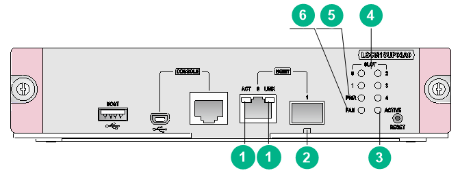
Figure 3-1 LSCM1SUP03A0 MPU LEDs
|
(1) Copper management Ethernet port LEDs (LINK and ACT) |
(2) Fiber management Ethernet port LED (LINK/ACT) |
|
(3) Active/standby state LED (ACTIVE) |
(4) Card status LEDs (SLOT) |
|
(5) Power module status LED (PWR) |
(6) Fan tray status LED (FAN) |
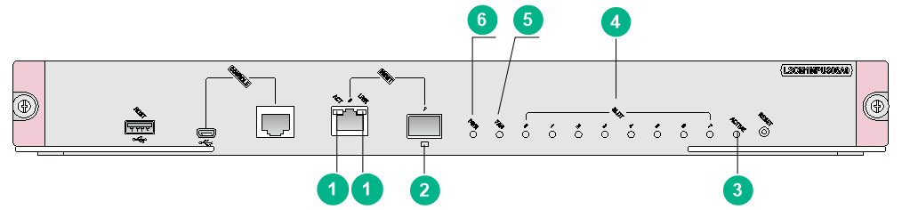
Figure 3-2 LSCM1MPUS06A0 MPU LEDs
|
(1) Copper management Ethernet port LEDs (LINK and ACT) |
(2) Fiber management Ethernet port LED (LINK/ACT) |
|
(3) Active/standby state LED (ACTIVE) |
(4) Card status LEDs (SLOT) |
|
(5) Fan tray status LED (FAN) |
(6) Power module status LED (PWR) |
|
|
NOTE: The LSCM3MPUS10B0 MPU is similar to the LSCM1MPUS06A0 MPU. This section uses the LSCM1MPUS06A0 MPU as an example. |
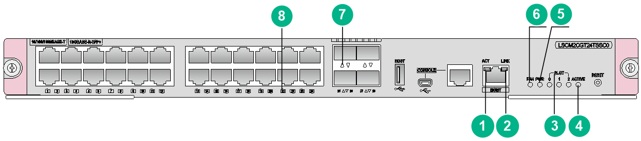
Figure 3-3 LSCM2CGT24TSSC0 MPU LEDs
|
(1) Copper management Ethernet port LED (ACT) |
(2) Copper management Ethernet port LED (LINK) |
|
(3) Card status LEDs (SLOT) |
(4) Active/standby state LED (ACTIVE) |
|
(5) Power module status LED (PWR) |
(6) Fan tray status LED (FAN) |
|
(7) SFP+ port LED |
(8) RJ-45 Ethernet port LED |
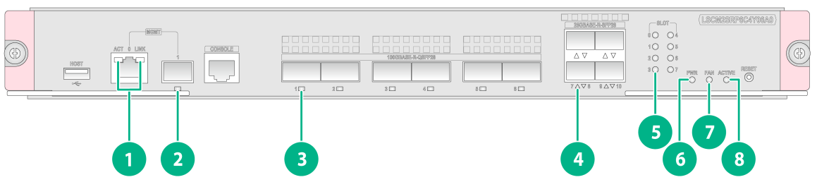
Figure 3-4 LSCM2SRP6C4Y06A0 MPU LEDs
|
(1) Copper management Ethernet port LEDs (LINK and ACT) |
(2) Copper management Ethernet port LED |
|
(3) QSFP28 port LED |
(4) SFP28 port LED |
|
(5) Card status LED |
(6) Power module status LED (PWR) |
|
(7) Fan tray status LED (FAN) |
(8) Active/standby state LED (ACTIVE) |
Management Ethernet port LEDs
Copper management Ethernet port LEDs
The MPUs provide a pair of LEDs (LINK and ACT) for each copper management Ethernet port to indicate its link status and data forwarding status.
Table 3-2 Copper management Ethernet port LED description
|
LINK LED status |
ACT LED status |
Description |
|
On |
Flashing |
A link is present, and the port is receiving or sending data. |
|
On |
Off |
A link is present. |
|
Off |
Off |
No link is present. |
Fiber management Ethernet port LED
The MPUs provide a LED for each fiber management Ethernet port to indicate its link status and data forwarding status.
Table 3-3 Fiber management Ethernet port LED description
|
LED status |
Description |
|
Flashing green |
A link is present, and the port is receiving or sending data. |
|
Steady green |
A link is present. |
|
Off |
No link is present. |
Power module status LED (PWR)
The MPUs provide a power module status LED (PWR) to indicate the power module status.
Table 3-4 Description for the power module status LED
|
PWR LED status (OK/FAIL) |
Description |
|
Steady green |
All power modules are operating correctly. |
|
Steady red |
A power module is not outputting power because one of the following conditions exists: · The power module is faulty or switched off. · The power cord is disconnected. · The power source is not supplying power. |
|
Off |
· No power modules are installed in the chassis. · No power modules are outputting power because one of the following conditions exists: ¡ The power modules are faulty or switched off. ¡ The power cords are disconnected. ¡ The power source is not supplying power. |
Fan tray status LED (FAN)
The MPUs provide a fan tray status LED (FAN) to indicate the fan tray status.
Table 3-5 Description for the fan tray status LED
|
FAN LED status (OK/FAIL) |
Description |
|
Steady green |
The fan tray is operating correctly. |
|
Steady red |
A fan problem has occurred or the fan tray is not in position. |
|
Off |
The switch is not powered on. |
Card status LEDs (SLOT)
Table 3-6 Description for the card status LED
|
SLOT LED status (RUN/ALM) |
Description |
|
Flashing green |
The card is operating correctly. |
|
Flashing green (four times per second) |
The card is loading software. If the LED flashes continuously, the software versions of the switch and the card do not match. |
|
Steady red |
The card is starting up or faulty. |
|
Flashing red |
The temperature of the card has exceeded the upper warning threshold or has dropped below the lower warning threshold. |
|
Off |
No card is present. |
Active/standby state LED (ACTIVE)
Table 3-7 MPU active/standby state LED description
|
ACTIVE LED status |
Description |
|
On |
The MPU is in active state. |
|
Off |
· The MPU is in standby state. · The MPU is faulty. Observe also the status LED for the MPU to determine whether the MPU is faulty. |
RJ-45 Ethernet port LEDs
The MPUs that have RJ-45 Ethernet ports provide a LED for each RJ-45 Ethernet port to indicate the link status and data receiving/forwarding status of the port.
Table 3-8 RJ-45 Ethernet port LED description
|
LED status |
Description |
|
Flashing |
The port is receiving or sending data. |
|
On |
A link is present. |
|
Off |
No link is present. |
SFP port LEDs
The MPUs that have SFP ports provide a LED for each SFP port to indicate the link status and data receiving/forwarding status of the port.
Table 3-9 SFP port LED description
|
LED status |
Description |
|
Flashing |
The port is receiving or sending data. |
|
On |
A link is present. |
|
Off |
No link is present. |
SFP+ port LEDs
The MPUs that have SFP+ ports provide a LED for each SFP+ port to indicate the link status and data receiving/forwarding status of the port.
Table 3-10 SFP+ port LED description
|
Status |
Description |
|
Flashing |
The port is receiving or sending data. |
|
On |
A link is present. |
|
Off |
No link is present. |
SFP28 port LEDs
The MPUs that have SFP28 ports provide a LED for each SFP28 port to indicate the link status and data receiving/forwarding status of the port.
Table 3-11 SFP28 port LED description
|
Status |
Description |
|
Flashing |
The port is receiving or sending data. |
|
On |
A link is present. |
|
Off |
No link is present. |
QSFP28 port LEDs
The MPUs that have QSFP28 ports provide a LED for each QSFP28 port to indicate the link status and data receiving/forwarding status of the port.
Table 3-12 QSFP28 port LED description
|
Status |
Description |
|
Flashing |
The port is receiving or sending data. |
|
On |
A link is present. |
|
Off |
No link is present. |
Interface module LEDs
Multiple interface modules are available for the switch. These interface modules provide different types and numbers of LEDs.
RJ-45 Ethernet port LEDs
Table 3-13 RJ-45 Ethernet port LED description
|
LED status |
Description |
|
Flashing |
The port is receiving or sending data. |
|
On |
A link is present. |
|
Off |
No link is present. |
SFP port LEDs
Table 3-14 SFP port LED description
|
LED status |
Description |
|
Flashing |
The port is receiving or sending data. |
|
On |
A link is present. |
|
Off |
No link is present. |
SFP+ port LEDs
The interface modules that have SFP+ ports provide a LED for each SFP+ port to indicate the link status and data receiving/forwarding status of the port.
Table 3-15 SFP+ port LED description
|
Status |
Description |
|
Flashing green |
The port is receiving or sending data at 10 Gbps. |
|
Flashing yellow |
The port is receiving or sending data at 1000 Mbps. |
|
On |
A link is present. |
|
Off |
No link is present. |
SFP28 port LEDs
The interface modules that have SFP28 ports provide a LED for each SFP28 port to indicate the link status and data receiving/forwarding status of the port.
Table 3-16 SFP28 port LED description
|
Status |
Description |
|
Flashing |
The port is receiving or sending data. |
|
On |
A link is present. |
|
Off |
No link is present. |
QSFP+ port LEDs
The interface modules provide a LED for each QSFP+ port to indicate the link status and data receiving/forwarding status of the port.
Table 3-17 QSFP+ port LED description
|
Status |
Description |
|
Flashing |
The port is receiving or sending data. |
|
On |
A link is present. |
|
Off |
No link is present. |
QSFP28 port LEDs
The interface modules provide a LED for each QSFP28 port to indicate the link status and data receiving/forwarding status of the port.
Table 3-18 QSFP28 port LED description
|
LED status |
Description |
|
Flashing |
The port is receiving or sending data. |
|
On |
A link is present. |
|
Off |
No link is present. |
|
|
NOTE: · The data rate of a QSFP28 port is 100 Gbps when its LED is green and 40 Gbps when its LED is yellow. |
Power module LEDs
PSR320-A
A PSR320-A power module provides a status LED to indicate its operating status.
Table 3-19 PSR320-A power module LED description
|
LED |
Status |
Description |
|
Status LED |
Green |
Normal operation |
|
Red |
Abnormal operation. Possible reasons include: · A power module alarm (such as input undervoltage, output short-circuit, output overcurrent, output overvoltage, or overtemperature) has occurred and the power module has entered protection state. · A power module fan failure has occurred. |
|
|
Off |
Abnormal power input. Possible reasons include: · The power module is faulty. · The power cord is disconnected. · The external power supply system is not available. The power module is switched off. |
PSR650-A/PSR650-D/PSR1200-A/PSR1200-D
The PSR650-A, PSR650-D, PSR1200-A, and PSR1200-D power modules each provide a status LED to indicate their operating status.
Table 3-20 PSR650-A/PSR650-D/PSR1200-A/PSR1200-D power module LEDs description
|
LED |
Status |
Description |
|
Status LED |
Green |
Normal operation |
|
Red |
Abnormal operation. Possible reasons include: · A power module alarm (such as input undervoltage, output short-circuit, output overcurrent, output overvoltage, or overtemperature) has occurred and the power module has entered protection state. · A power module fan failure has occurred. |
|
|
Off |
Abnormal power input. Possible reasons include: · The power module is faulty. · The power cord is disconnected. · The external power supply system is not available. The power module is switched off. |
PSR650C-12A/PSR650C-12D/PSR1400-A/PSR2500-12AHD/PSR2500-12D
The PSR650C-12A, PSR650C-12D, PSR1400-A, PSR2500-12AHD, and PSR2500-12D power modules each provide three LEDs INPUT, OUTPUT, and FAN to indicate their operating status.
Table 3-21 PSR650C-12A/PSR650C-12D/PSR1400-A/PSR2500-12AHD/PSR2500-12D power module LEDs description
|
LED |
Status |
Description |
|
INPUT |
Green |
Normal power input |
|
Red |
Abnormal power input. The input voltage is out of the rated voltage range. |
|
|
Off |
No power input. Possible reasons include: · The power module is faulty. · The power cord is disconnected. · The external power supply system is not available. |
|
|
OUTPUT |
Green |
Normal power output |
|
Red |
Abnormal power output. Possible reasons include: · A power module alarm (such as input undervoltage, output short-circuit, output overcurrent, output overvoltage, or overtemperature) has occurred and the power module has entered protection state. · The power module is switched off. |
|
|
Off |
No power output. Possible reasons include: · The power module is faulty. · The power cord is disconnected. · The external power supply system is not available. |
|
|
FAN |
Green |
The fan in the power module is operating correctly. |
|
Red |
The fan in the power module is operating incorrectly. Possible reasons include: · A power module fan failure has occurred. · The power module is switched off. |
|
|
Off |
The fan in the power module is not operating. Possible reasons include: · The power module is faulty. · The power cord is disconnected. · The external power supply system is not available. |
PSR1400-12D1
A PSR1400-12D1 power module provides three LEDs INPUT, OUTPUT, and FAN to indicate its operating status.
Table 3-22 PSR1400-12D1 power module LEDs description
|
LED |
Status |
Description |
|
INPUT |
Green |
Normal power input. |
|
Red |
Abnormal power input. The input voltage is out of the rated voltage range. |
|
|
Off |
No power input. Possible reasons include: · The power module is faulty. · The power cord is disconnected. · The external power supply system is not available. · The system power output switch is turned off. |
|
|
OUTPUT |
Green |
Normal power output |
|
Red |
Abnormal power output. A power module alarm (such as output short-circuit, output overcurrent, output overvoltage, or overtemperature) has occurred and the power module has entered protection state. |
|
|
Off |
No power output. Possible reasons include: · The power module is faulty. · The power cord is disconnected. · The external power supply system is not available. · The system power output switch is turned off. |
|
|
FAN |
Green |
The fan in the power module is operating correctly. |
|
Red |
The fan in the power module is operating incorrectly. A power module fan failure has occurred. |
|
|
Off |
The fan in the power module is not operating. Possible reasons include: · The power module is faulty. · The power cord is disconnected. · The external power supply system is not available. · The system power output switch is turned off. |
PSR2800-ACV
A PSR2800-ACV power module provides five LEDs INPUT, OUTPUT, FAN, PoE INPUT, and PoE OUTPUT to indicate its operating status.
Table 3-23 PSR2800-ACV power module LED description
|
LED |
Status |
Description |
|
INPUT |
Green |
Normal power input. |
|
Red |
Abnormal power input. The input voltage is out of the rated voltage range. |
|
|
Off |
· The power module is faulty. · No power input. Possible reasons include: ¡ The system input power cord is disconnected. ¡ The external power supply system is not available. |
|
|
OUTPUT |
Green |
Normal power output |
|
Red |
Abnormal power output. Possible reasons include: · A power module alarm (such as input undervoltage, output short-circuit, output overcurrent, output overvoltage, or overtemperature) has occurred and the power module has entered protection state. · The system power switch is turned off. |
|
|
Off |
· The power module is faulty. · No power input. Possible reasons include: ¡ The system input power cord is disconnected. ¡ The external power supply system is not available. |
|
|
FAN |
Green |
The fan in the power module is operating correctly. |
|
Red |
The fan in the power module is operating incorrectly. Possible reasons include: · A power module fan failure has occurred. · The system power switch is turned off. |
|
|
Off |
· The power module is faulty. · The power module does have power input. Possible reasons include: ¡ The system input power cord is disconnected. ¡ The external power supply system is not available. |
|
|
PoE INPUT |
Green |
Normal PoE power input |
|
Red |
Abnormal PoE power input. The PoE input voltage is out of the rated voltage range. |
|
|
Off |
No PoE power input. Possible reasons include: · The power module is faulty. · The PoE input power cord is disconnected. · The external power supply system is not available. |
|
|
PoE OUTPUT |
Green |
Normal PoE power output |
|
Red |
Abnormal PoE power output. Possible reasons include: · The PoE output voltage is out of the rated voltage range. · The PoE power switch is turned off. |
|
|
Off |
No PoE power output. Possible reasons include: · The power module is faulty. · The PoE input power cord is disconnected. · The external power supply system is not available. |
