- Table of Contents
- Related Documents
-
| Title | Size | Download |
|---|---|---|
| 03-Cables | 714.96 KB |
3 Cables
This chapter describes cables used for connecting network ports.
Table3-1 Cable description
|
Cable |
Ports connected |
Application |
Reference |
|
Console cable |
Console port at the device end and 9-pin serial port at the other end |
Connects the console port of the router to the console terminal. |
|
|
DC power cord |
Power input interface at the device end and power stud at the other end |
Connects a power supply to the power source |
|
|
AC power cord |
Power input interface at the device end and AC power receptacle at the other end |
Connects a power supply to the power receptacle |
|
|
Grounding cable |
Grounding point at the device end and the grounding stud at the other end |
Grounds the device |
|
|
Clock cable |
Clock interfaces |
Transmits clock signals |
|
|
Ethernet twisted pair cable |
RJ-45 Ethernet ports |
Connects RJ-45 Ethernet ports to transmit data. |
|
|
Optical fiber |
QSFP28/SFP+/SFP ports |
Connects the fiber ports to transmit data. |
|
|
E1 cable |
E1-HM96 Ethernet copper ports |
Connects E1-HM96 Ethernet copper ports to transmit data. |
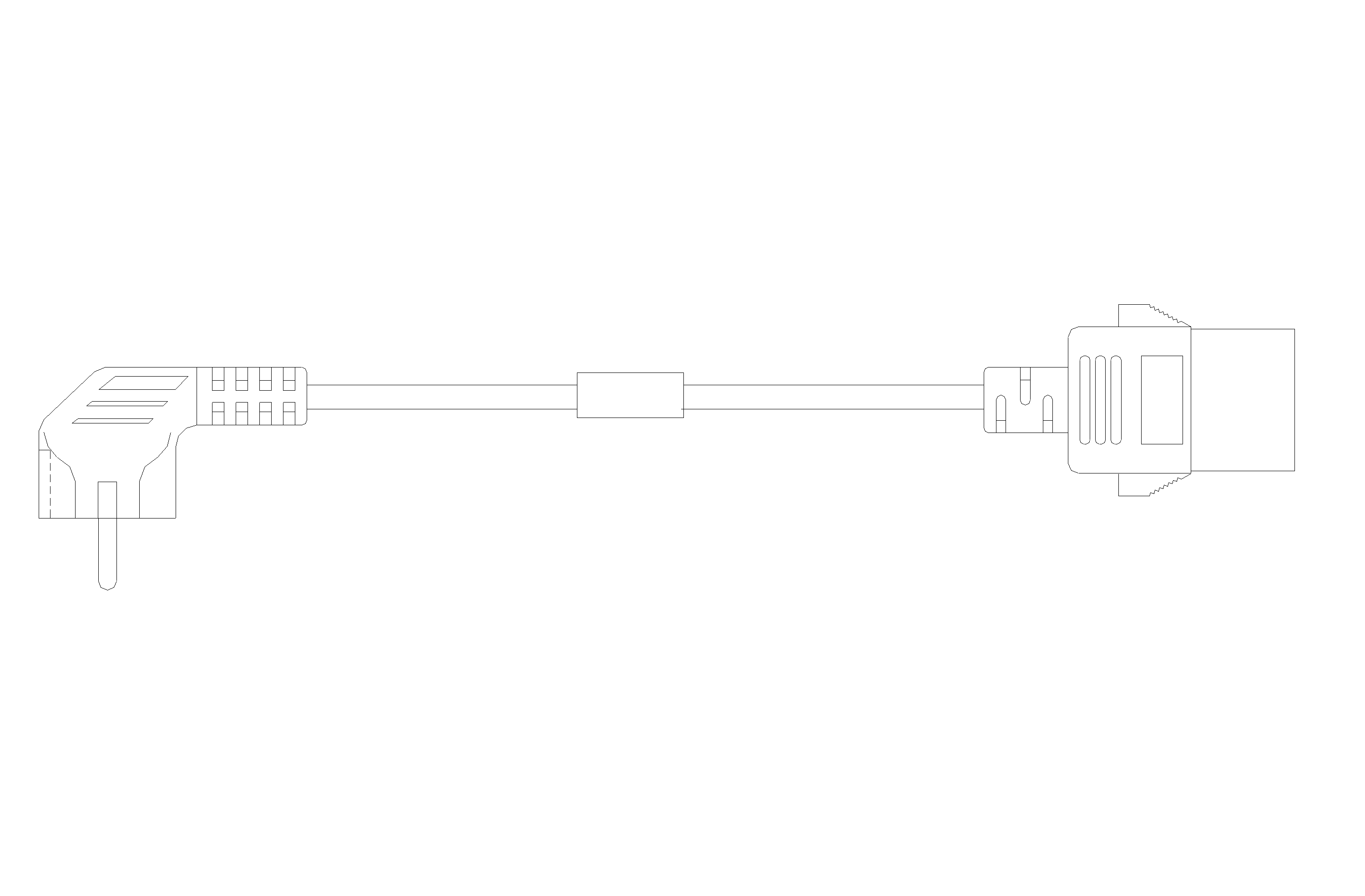
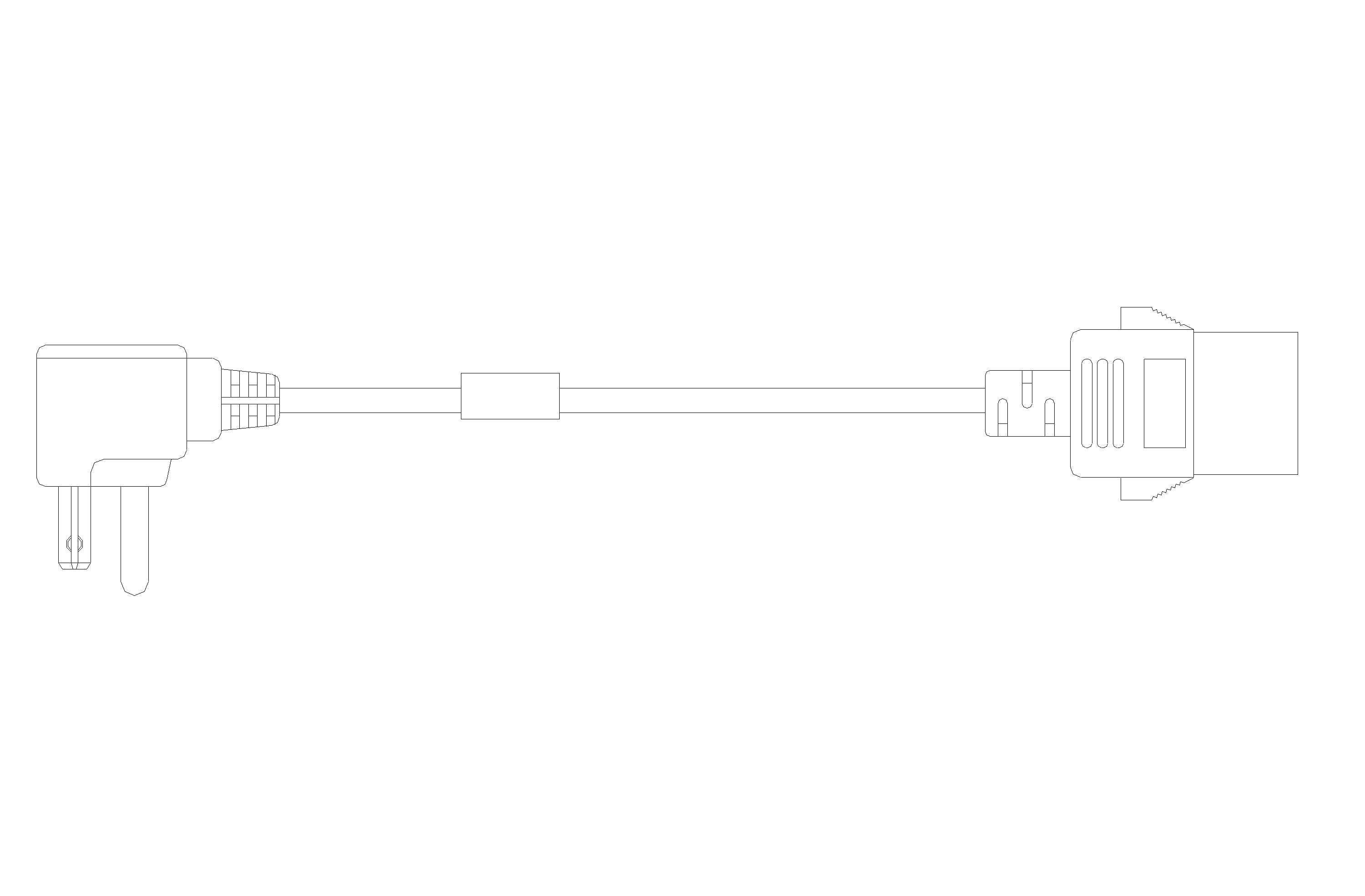
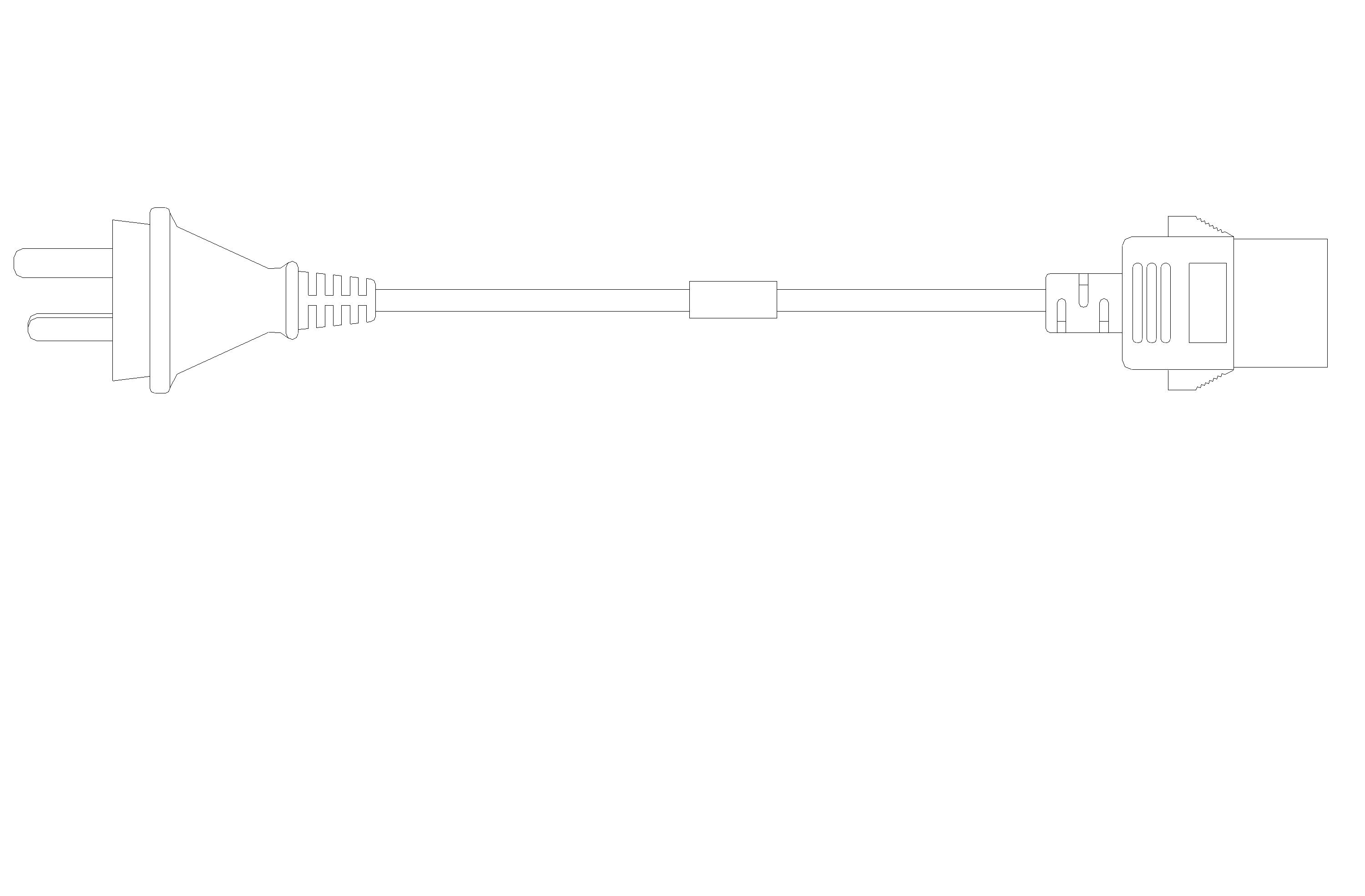
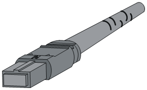
Console cable
A Console cable connects the console port on a device and the serial port on a terminal.
Figure3-1 Console cable
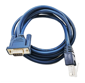
Table3-2 Console cable specifications
|
Item |
Description |
|
RJ-45 connector |
RJ-45 Connector-Registered Jack-8PIN-8bit-Shielded-Connector |
|
DB-9 connector |
Cable Connector-D Connector-9PIN-Female Socket |
|
Cable model |
Twisted-Pair Cable-UL2464-0.32mm-28AWG-2P-PANTONE WARM GRAY 1U-Only For OEM |
|
Cores |
4 |
|
Flame retardant grade |
VW-1 |
|
Length |
3 m (9.84 ft) |
The console cable has an 8-core crimped RJ-45 connector for connecting to the console port of the router, and a DB-9 connector for connecting to the 9-core serial port of the terminal.
Figure3-2 shows the console cable and Table3-3 shows its pinouts.
Figure3-2 Console cable connecting the serial port and the console port
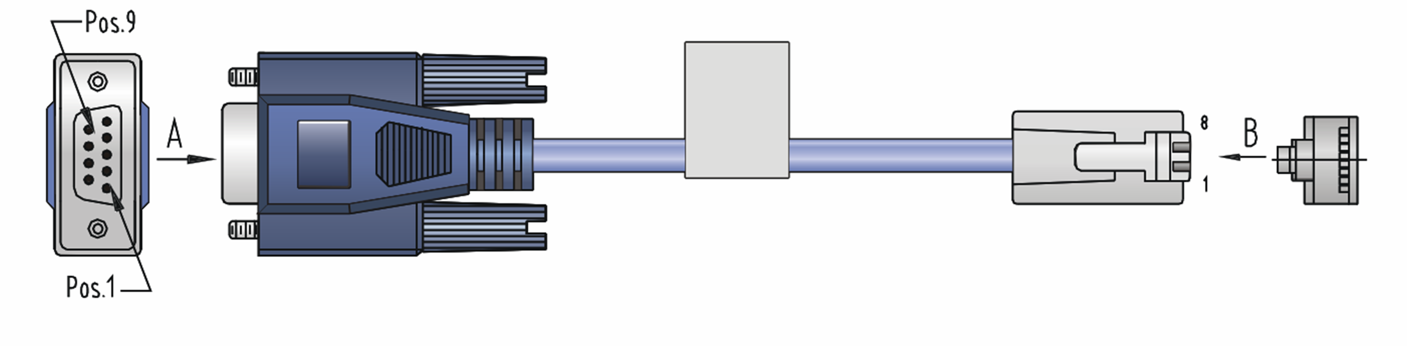
Table3-3 Pinouts for the console cable connecting the serial port and the console port
|
RJ-45 pin |
Signal |
DB-9 pin |
Signal |
|
1 |
RTS |
8 |
CTS |
|
2 |
DTR |
6 |
DSR |
|
3 |
TXD |
2 |
RXD |
|
4 |
CD |
5 |
SG |
|
5 |
GND |
5 |
SG |
|
6 |
RXD |
3 |
TXD |
|
7 |
DSR |
4 |
DTR |
|
8 |
CTS |
7 |
RTS |
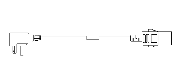
DC power cord
A DC power cord connects a DC power supply to an external DC power source. Power cords supported by the PSR2400-12D, PSR2400-D, and PSR2500B-12AHD-F power supplies are as shown in Table3-4.
Table3-4 Compatible power cords
|
Item |
Power cord code |
Cable length |
Wire diameter |
Remarks |
Description |
|
DC power cord |
0404A0E1 |
3 m (9.84 ft) |
6 AWG |
Black and blue power cord (ring terminal included) |
Used for the PSR2400-12D power supply on the CR16000-M |
|
DC power cord |
0404A0E2 |
15 m (49.21 ft) |
6 AWG |
Black and blue power cord (ring terminal included) |
|
|
DC power cord |
0404A1M5 |
20 m (65.62 ft) |
4 AWG |
Blue and red power cord (ring terminal included) |
Used for the PSR2400-D power supply on the CR16000-M |
|
DC power cord |
0404A1M6 |
15 m (49.21 ft) |
4 AWG |
Blue and red power cord (ring terminal included) |
|
|
DC power cord |
0404A1M7 |
10 m (32.81 ft) |
6 AWG |
Blue and red power cord (ring terminal included) |
|
|
DC power cord |
0404A1MD |
30 m (98.43 ft) |
4 AWG |
Blue and red power cord (ring terminal included) |
|
|
High-voltage DC power cord |
0404A0RL |
3 m (9.84 ft) |
3*2.5 mm2 |
Black power cord (ring terminal included) |
Used for the PSR2500B-12AHD-F power supply on the CR16000-M |
Figure3-3 PSR2400-12D DC power cord (black and blue cable as an example)
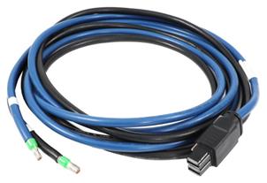
Figure3-4 Ring terminal
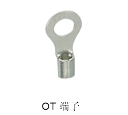
Figure3-5 PSR2400-D DC power cords
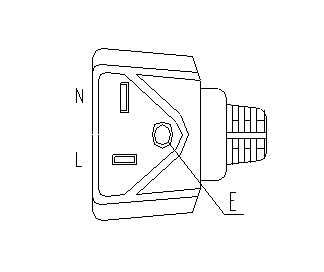
AC power cord
An AC power cord connects an AC power supply to an external AC power source.
· The power of a power supply has requirements on the current-carrying capacity of the AC power cord. Select an appropriate AC power cord based on the actual requirements.
· Available power plugs vary by country or region. Select the AC power cord that meets the requirements of the plug standard.
· AC power supplies of the CR16000-M require 16A AC power cords. For power plugs required by different countries or regions, see Table3-5.
|
Code |
Description |
Power cord appearance (User side plug-Device side plug) |
|
04043396 |
External Power Cable-China AC 220V16A-3m-3*1.5mm^2-Black-(PI-Angle Male)-(227IEC53-1.5^2(3C))-(C19-Straight Female) |
|
|
0404A0C2 |
External Power Cable-China AC 220V16A-3m-3*1.5mm^2-Black-(C20-Straight Male)-(227IEC53-1.5^2(3C))-(C19-Straight Female)-PDU |
|
|
0404A063 |
America AC Power Cable 125V20A-3m-3X3.30mm^2-Black-(PM-Angle Male)-(12SJT(3C)Black)-(C19-Straight Female) |
|
|
0404A061 |
Europe AC Power Cable 250V16A-3m-3*1.50mm^2-Black-(PF-Angle Male)-(H05VV-F-1.5^2(3C)Black)-(C19 Straight Female) |
|
|
0404A062 |
External AC Power Cable-Japan AC Power Cable 125V20A-3m-3*3.50mm^2-Black-(PM-Angle Male)-(HVCTF-3.5^2(3C))-(C19 Straight Female) |
|
|
0404A01A |
Australia AC Power Cable 250V16A-3m-3*1.5mm^2-Black-(PI-Straight Male)-(H05VVF 3*1.5mm^2)-(C19 Straight Female) |
|
|
0404A0RQ |
External AC Power Cable-3m-3*1.5mm^2-Black-(PW3C-16A450V)-(227IEC53(RVV)3*1.5mm^2 Black)-(PI-16A250V-Straight Male) |
|
|
|
NOTE: Select the power cord according to the country or region. |
Grounding cable
A grounding cable is used to connect a chassis or cabinet to the grounding point.
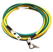
Table3-6 Grounding cable specifications
|
Item |
Description |
|
|
PGND cable |
Ring terminal |
2-Hole Ring Terminal-JG2(6AWG-M6-0) |
|
Cable model |
Power Cable-600V UL10455(6AWG)-83A Yellow/Green |
|
|
Flame retardant grade |
CM |
|
Clock cable
Clock cable for common MPUs
If connected to the clock interface of an external device through a clock cable, a router can receive 2-way 2.048MHz/2.048Mbit/s clock synchronization signals from the uplink device and provides 2-way 2.048MHz/2.048Mbit/s signals to the downlink.
A clock cable for common MPUs has an SMB connector at one end for connecting the clock interface on a router. The connector at the other end varies by the clock interface type on the external device.
Clock cable for 1588v2-capable MPUs
If connected to the clock interface of an external device through a clock cable, a router can receive 2Mbps/2MHz/1PPS+TOD clock signals from the uplink device and provides 2Mbps/2MHz/1PPS+TOD signals to the downlink.
75ohm clock cables and 120ohm clock cables are available for 1588v2-capable MPUs. A 75ohm clock cable is used to transmit 2Mbps and 2MHz clock signals and a 120ohm clock cable is used to transmit 1PPS+TOD clock signals.
At the router end, a 75ohm clock cable provides an SMB connector and a 120ohm clock cable provides an RJ-45 connector. The connector at the other end varies by the clock interface type on the external device.
Figure3-7 75ohm clock cable
Figure3-8 75ohm clock cable connector at the route side
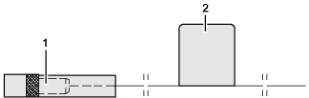
|
(1) Coaxial connector-SMB |
(2) Label |
Table3-7 displays the pinouts for the RJ-45 connector of a 120ohm cable.
Table3-7 Pinouts for the RJ-45 connector of a 120ohm cable
|
RJ-45 |
Signal |
Description |
|
1 |
NC |
N/A |
|
2 |
NC |
N/A |
|
3 |
422_1_N |
1PPS |
|
4 |
GND |
Grounding |
|
5 |
GND |
Grounding |
|
6 |
422_1_P |
1PPS |
|
7 |
422_2_N |
TOD time information |
|
8 |
422_2_P |
TOD time information |
Ethernet twisted pair cable
An Ethernet twisted pair cable consists of four pairs of insulated wires twisted together. It mainly transmits analog signals and is advantageous in transmitting data over shorter distances. The maximum transmission distance is 100 m (328.08 ft).
RJ-45 connector
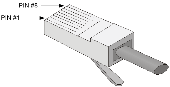
An Ethernet twisted pair cable connects network devices through the RJ-45 connectors at the two ends. Figure3-9 shows the pinouts of an RJ-45 connector.
Figure3-9 RJ-45 connector pinout diagram
Cable pinouts
EIA/TIA cabling specifications define two standards: 568A and 568B for cable pinouts.
· Standard 568A—pin 1: white/green stripe, pin 2: green solid, pin 3: white/orange stripe, pin 4: blue solid, pin 5: white/blue stripe, pin 6: orange solid, pin 7: white/brown stripe, pin 8: brown solid.
· Standard 568B—pin 1: white/orange stripe, pin 2: orange solid, pin 3: white/green stripe, pin 4: blue solid, pin 5: white/blue stripe, pin 6: green solid, pin 7: white/brown stripe, pin 8: brown solid.
|
|
NOTE: White/green represents light green or a white wire with green strips or dots. White/orange, white/blue, and white/brown are the same. |
Cable type
Based on performance
Table3-8 Ethernet cable description
|
Type |
Description |
|
Category 5 |
Transmits data at a maximum speed of 100 Mbps, with a bandwidth of 100 MHz. |
|
Category 5e |
Transmits data at a maximum speed of 1000 Mbps, with a bandwidth of 100 MHz. |
|
Category 6 |
Transmits data at a speed higher than 1 Gbps, with a bandwidth of 250 MHz. |
|
Category 6A |
Transmits data at a speed higher than 10 Gbps, with a bandwidth of 500 MHz. |
|
Category 7 |
Transmits data at a speed higher than 10 Gbps, with a bandwidth of 600 MHz. |
A category 5 cable has a transmission frequency of 100MHz and is used for voice and data transmission, mainly for 100BASE-T and 10BASE-T networks. It is the most commonly used Ethernet cable and can also be used to transmit 1000M Ethernet data.
A category 5e cable has low attenuation, less crosstalk, higher attenuation crosstalk ratio (ACR), shorter delay, and greatly improved performance over category 5 cables. Category 5 cables are mainly used for 1000M Ethernet.
The transmission frequency of category 6 is 1MHz to 250MHz. Category 6 cables provide improved performance in terms of crosstalk and return loss, which is extremely important for the new generation of full-duplex, high-speed network applications. Category 6 cabling systems have a large margin of power sum attenuation crosstalk ratio (PS-ACR) at 200MHz, which provides two times the bandwidth of category 5e, and its transmission performance is much higher than the category 5e standard. Category 6 is the most suitable for applications with a transmission rate higher than 1Gbps.
Note that 10/100M Ethernet uses only two pairs of wires, white/orange, orange, white/green, and green, to send and receive data, and 1000M Ethernet uses four pairs of twisted pair wires.
|
|
NOTE: The 10 Gbps RJ-45 Ethernet ports use category 6A or category 7 Ethernet twisted pair cables for connection. Other RJ-45 Ethernet ports use category 5 or higher Ethernet twisted pair cables for connection. |
Based on pinouts
Ethernet twisted pair cables can be classified into straight through and crossover cables based on their pinouts.
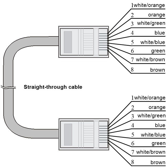
· Straight-through—The pinouts at both ends comply with standard 568B, as shown in Figure3-10.
· Crossover—The pinouts at one end comply with standard 568B, and those at the other end comply with standard 568A, as shown in Figure3-11.
Figure3-10 Straight-through cable

|
|
NOTE: Refer to the figures above when distinguishing and making Ethernet cables, and strictly follow the line sequence. If you fail to do so, the communication quality will be affected even if the equipment at both ends can be connected. |
Pin assignments
Select an Ethernet twisted pair cable according to the RJ-45 Ethernet interface type on your device. An RJ-45 Ethernet interface can be MDI (for routers and PCs) or MDIX (for routers). For the pinouts of RJ-45 Ethernet interfaces, see Table3-9 and Table3-10.
Table3-9 RJ-45 MDI interface pinouts
|
10BASE-T/100BASE-TX |
1000BASE-T |
|||
|
Signal |
Function |
Signal |
Function |
|
|
1 |
Tx+ |
Send data |
BIDA+ |
Bi-directional data cable A+ |
|
2 |
Tx- |
Send data |
BIDA- |
Bi-directional data cable A- |
|
3 |
Rx+ |
Receive data |
BIDB+ |
Bi-directional data cable B+ |
|
4 |
Reserved |
N/A |
BIDC+ |
Bi-directional data cable C+ |
|
5 |
Reserved |
N/A |
BIDC- |
Bi-directional data cable C- |
|
6 |
Rx- |
Receive data |
BIDB- |
Bi-directional data cable B- |
|
7 |
Reserved |
N/A |
BIDD+ |
Bi-directional data cable D+ |
|
8 |
Reserved |
N/A |
BIDD- |
Bi-directional data cable D- |
Table3-10 RJ-45 MDI-X interface pinouts
|
Pin |
10BASE-T/100BASE-TX |
1000BASE-T |
||
|
Signal |
Function |
Signal |
Function |
|
|
1 |
Rx+ |
Receive data |
BIDB+ |
Bi-directional data cable B+ |
|
2 |
Rx- |
Receive data |
BIDB- |
Bi-directional data cable B- |
|
3 |
Tx+ |
Send data |
BIDA+ |
Bi-directional data cable A+ |
|
4 |
Reserved |
N/A |
BIDD+ |
Bi-directional data cable D+ |
|
5 |
Reserved |
N/A |
BIDD- |
Bi-directional data cable D- |
|
6 |
Tx- |
Send data |
BIDA- |
Bi-directional data cable A- |
|
7 |
Reserved |
N/A |
BIDC+ |
Bi-directional data cable C+ |
|
8 |
Reserved |
N/A |
BIDC- |
Bi-directional data cable C- |
To ensure normal communication, the pins for sending data on one port should correspond to the pins for receiving data on the peer port. When both of the ports on the two devices are MDI or MDIX, a crossover Ethernet cable is needed. A cross-over cable connects devices of the same type. When one port is MDI and the other is MDIX, a straight-through Ethernet cable is needed. A straight-through cable connects devices of different types.
The RJ-45 Ethernet ports on the router support auto-MDI/MDIX. By default, auto-MDI/MDIX is enabled on a port.
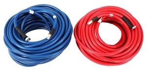
Optical fiber
|
|
CAUTION: Use the same types of transceiver modules, pigtail cords, patch cords, and fiber cables. If you use single-mode optical fibers, the transceiver modules, pigtail cords, patch cords, and fiber cables must be single-mode. |
Optical fiber
Optical fibers are widely used in fiber-optic communications, which are advantageous for long-distance communications.
Optical fibers can be classified into the following types:
· Single mode fiber—It has a core size of 10 µm or smaller, and has a lower modal dispersion. It carries only a single ray of light. It is mostly used for communication over longer distances.
· Multi-mode fiber—It has a core size of 50 µm or 62.5 µm or higher, and has a higher modal dispersion than single-mode optical fiber. It is mostly used for communication over shorter distances.
Table3-11 Allowed maximum tensile force and crush load
|
Period of force |
Tensile load (N) |
Crush load (N/mm) |
|
Short period |
150 |
500 |
|
Long term |
80 |
100 |
Optical fiber cable
An optical fiber cable is a cable containing one or more optical fibers. Typically, the optical fiber elements are individually coated with plastic layers and contained in a protective tube. Optical fiber cables contain single-mode and multi-mode optical fiber cables.
Patch cord
A fiber that has connectors at both ends is called a patch cord. A patch cord connects one optical device to another for signal routing. Patch cords contain single-mode and multi-mode patch cords.
· Single-mode patch cord—The jacket is yellow. It permits transmission over longer distances.
· Multi-mode patch cord—The jacket is orange. It permits transmission over shorter distances.
Patch cords are mainly classified into SC, LC, and FC based on interface type. The typical length of a patch cord can be 0.5 m (1.64 ft), 1 m (3.28 ft), 2 m (6.56 ft), 3 m (9.84 ft), 5 m (16.40 ft), and 10 m (32.81 ft).
Pigtail cord
A pigtail cord is an optical fiber that has an optical connector on one end and a length of exposed fiber on the other. The end of the pigtail is fusion spliced to a fiber, connecting the fiber cable and transceiver.
Pigtail cords contain single-mode (yellow) and multi-mode (orange) pigtail cords. Based on interface type, pigtail cords can also be classified into two main types, LC and FC.
Fiber connector
When you plug or unplug an LC optical connector, follow these restrictions and guidelines:
· Do not rotate the connector.
· When insert the connector into a fiber port, carefully align the connector with the port and gently insert it into the port without using any excessive force.
· When unplug the connector from a fiber port, pinch the clip on the connector, slightly press the connector into the port, and then pull the connector out.
Figure3-13 MPO connector
When you plug or unplug an MPO optical connector, follow these restrictions and guidelines:
· Do not rotate the connector.
· When insert the connector into a fiber port, carefully align the connector with the port and gently insert it into the port without using any excessive force.
· When unplug the connector from a fiber port, pull the unlocking sleeve, and then pull the connector out.
Precautions
· Make sure the fiber connector and fiber type match the transceiver module type.
· The fiber ports on some cards have shielded covers. Remove the shielded covers before using the fiber ports. Fiber interfaces must be installed with shielded covers when they are not in use. Keep them safely.
· Fiber connectors must be protected under safe and reliable outer packing, and be fitted with dust caps. Fiber connectors must be installed with dust caps when they are not in use. Take care not to scratch their end face. Replace the dust cap if it is loose or polluted.
· Before connecting a fiber, use dust free paper and absolute alcohol to clean the end face of the fiber connector. You can brush the end face only in one direction. You also need to brush the end face of the fiber port.
· If the fiber has to pass through a metallic board hole, the hole must have a sleek and fully filleted surface (the filleting radius must be not less than 2 mm). When passing through a metallic board hole or bending along the acute side of mechanical parts, the fiber must wear jackets or cushions.
· Insert and remove a plug with care. Never exert a fierce force to the fiber or plug; otherwise the plug might be damaged or the fiber might be broken. Never pull, press or extrude the fiber fiercely. For the allowed maximum tensile load and crush load, see Table3-11.
E1 cable
You can use an E1 cable to connect E1-HM96 Ethernet copper ports.
Figure3-14 E1 cable (1)
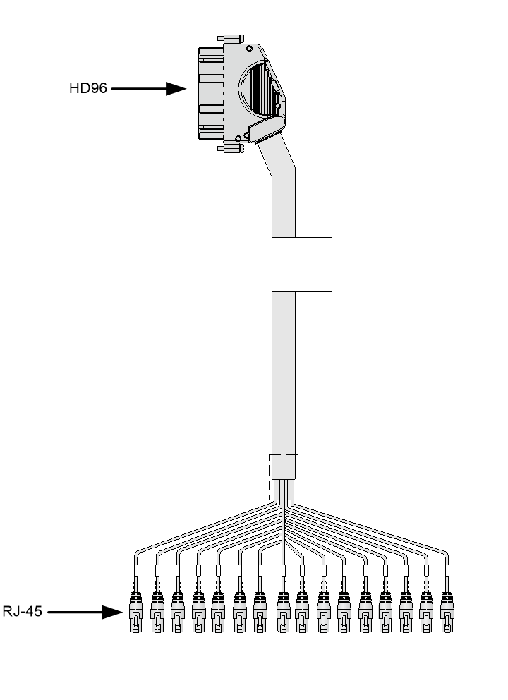
Figure3-15 E1 cable (2)
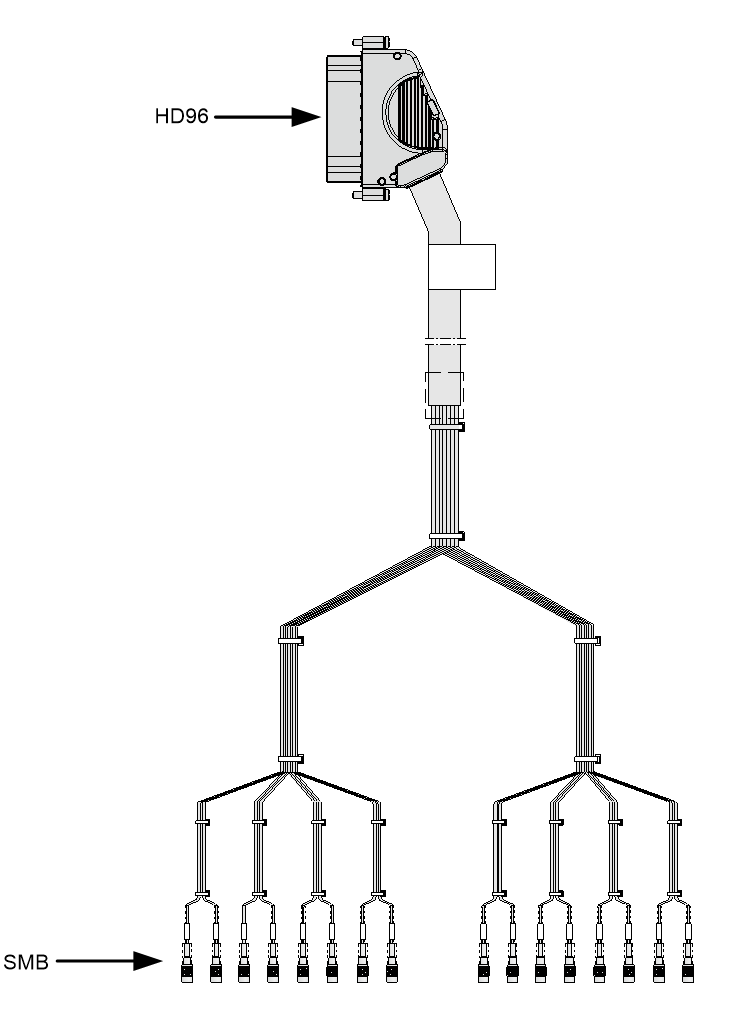
Figure3-16 E1 cable (3)

