- Table of Contents
- Related Documents
-
| Title | Size | Download |
|---|---|---|
| 02-FRUs and compatibility matrixes | 178.52 KB |
2 FRUs and compatibility matrixes
For more information about FRUs, see the corresponding module manual, such as Ethernet interface module manual.
Technical specifications
Module specifications
Table2-1 displays specifications of FRUs supported by the CR16000-M.
Table2-1 Module specifications
|
Module |
Model |
Net weight |
Dimensions |
Min power consumption |
Max power consumption |
||
|
Height |
Width |
Depth |
|||||
|
MPU |
SR07MPUA3-M |
1.20 kg (2.65 lb) |
22 mm (0.87 in) |
214 mm (8.43 in) |
262 mm (10.32 in) |
46 W |
53 W |
|
Interface module |
MIC-CLP4L-M |
1.15 kg (2.54 lb) |
22 mm (0.87 in) |
214 mm (8.43 in) |
262 mm (10.32 in) |
32 W |
35 W |
|
MIC-CQ1L-M |
1.05 kg (2.31 lb) |
22 mm (0.87 in) |
214 mm (8.43 in) |
262 mm (10.32 in) |
16 W |
18 W |
|
|
MIC-CQ1LF-M |
1.10 kg (2.43 lb) |
22 mm (0.87 in) |
214 mm (8.43 in) |
262 mm (10.32 in) |
38 W |
50 W |
|
|
MIC-CQ2L-M |
1.10 kg (2.43 lb) |
22 mm (0.87 in) |
214 mm (8.43 in) |
262 mm (10.32 in) |
26 W |
28 W |
|
|
MIC-ET16L-M |
1.16 kg (2.56 lb) |
22 mm (0.87 in) |
214 mm (8.43 in) |
262 mm (10.32 in) |
29 W |
31 W |
|
|
MIC-GP12L-M |
1.20 kg (2.65 lb) |
22 mm (0.87 in) |
214 mm (8.43 in) |
262 mm (10.32 in) |
36 W |
38 W |
|
|
MIC-GP24L-M |
1.50 kg (3.31 lb) |
44 mm (1.73 in) |
214 mm (8.43 in) |
262 mm (10.32 in) |
29 W |
42 W |
|
|
MIC-GT12L-M |
1.28 kg (2.82 lb) |
22 mm (0.87 in) |
214 mm (8.43 in) |
262 mm (10.32 in) |
30 W |
32 W |
|
|
MIC-PSP4L-M |
1.10 kg (2.43 lb) |
22 mm (0.87 in) |
214 mm (8.43 in) |
262 mm (10.32 in) |
40 W |
50 W |
|
|
MIC-SP4L-M |
1.10 kg (2.43 lb) |
22 mm (0.87 in) |
214 mm (8.43 in) |
262 mm (10.32 in) |
32 W |
35 W |
|
|
MIC-TCP8L-M |
1.25 kg (2.76 lb) |
22 mm (0.87 in) |
214 mm (8.43 in) |
262 mm (10.32 in) |
43 W |
45 W |
|
|
MIC-XP4L-M |
1.10 kg (2.43 lb) |
22 mm (0.87 in) |
214 mm (8.43 in) |
262 mm (10.32 in) |
14 W |
16 W |
|
|
MIC-XP10L-M |
1.10 kg (2.43 lb) |
22 mm (0.87 in) |
214 mm (8.43 in) |
262 mm (10.32 in) |
35 W |
50 W |
|
|
Switching fabric module |
SFE-A |
3.70 kg (8.16 lb) |
44 mm (1.73 in) |
429 mm (16.89 in) |
264 mm (10.39 in) |
210 W |
280 W |
|
|
NOTE: The card dimensions are expressed in Height (H) × Width (W) × Depth (D) format. · H—Height of the front panel of the card. · W—Width of the front panel of the card. · D—Depth from the front panel of the card to the connector. |
Power supply specifications
Table2-2 displays specifications of power supplies supported by the CR16000-M.
Table2-2 Power supply specifications
|
Model |
Net weight |
Dimensions |
||
|
Height |
Width |
Depth |
||
|
PSR1200B-12A |
2.27 kg (5.00 lb) |
41 mm (1.61 in) |
102 mm (4.02 in) |
410 mm (16.14 in) |
|
PSR2500-12A |
2.50 kg (5.51 lb) |
41 mm (1.61 in) |
102 mm (4.02 in) |
410 mm (16.14 in) |
|
PSR2400-12D |
2.40 kg (5.29 lb) |
41 mm (1.61 in) |
102 mm (4.02 in) |
410 mm (16.14 in) |
|
PSR2400-D |
2.40 kg (5.29 lb) |
41 mm (1.61 in) |
102 mm (4.02 in) |
410 mm (16.14 in) |
|
PSR2500B-12AHD-F |
2.75 kg (6.06 lb) |
41 mm (1.61 in) |
102 mm (4.02 in) |
410 mm (16.14 in) |
Fan tray specifications
Table2-3 displays specifications of fan trays supported by the CR16000-M.
Table2-3 Fan tray specifications
|
Fan tray |
Net weight |
Dimensions (lying flat on a workbench) |
Min power consumption |
Max power consumption |
||
|
Height |
Width |
Depth |
||||
|
CR16000-M8 fan tray |
0.95 kg (2.09 lb) |
200 mm (7.87 in) |
86 mm (3.39 in) |
120 mm (4.72 in) |
9 W |
95 W |
|
CR16000-M16 fan tray |
1.30 kg (2.87 lb) |
289 mm (11.38 in) |
86 mm (3.39 in) |
120 mm (4.72 in) |
12 W |
140 W |
LEDs
The MPUs, interface modules, switching fabric modules, fan trays, and power supplies available for the CR16000-M provide LEDs to indicate their operating status.
|
LEDs at a glance |
|
MPU LEDs: · Management Ethernet port LEDs |
|
Interface module LEDs: |
|
Switching fabric module LEDs: · Switching fabric module running status LED |
MPU LEDs
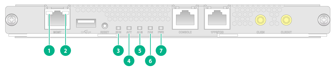
Figure2-1 shows the LEDs on the MPU of the CR16000-M.
|
(1) Management Ethernet port LED (LINK) |
(2) Management Ethernet port LED (ACT) |
|
(3) MPU running status LED |
(4) MPU active/standby state LED |
|
(5) MPU alarm status LED |
(6) Fan tray status LED |
|
(7) Power status LED |
|
Management Ethernet port LEDs
Table2-4 Management Ethernet port LED description
|
LINK LED status |
ACT LED status |
Description |
|
On |
Flashing |
A link is present, and the management Ethernet port is receiving or sending data. |
|
On |
Off |
A link is present, but the management Ethernet port is not receiving or sending data. |
|
Off |
Off |
No link is present. |
MPU running status LED
Table2-5 MPU running status LED description
|
RUN LED status |
Description |
|
Flashing (0.5 Hz) |
The MPU is operating correctly. |
|
Fast flashing (4 Hz) |
The MPU is starting up. |
|
Steady on |
The MPU is faulty. |
|
Off |
The MPU is not powered on. |
MPU active/standby status LED
The ACT LED indicates the active or standby operating mode of the MPU.
Table2-6 MPU active/standby status LED description
|
ACT LED status |
Description |
|
On |
The MPU is operating in active mode. |
|
Off |
· The MPU is operating in standby mode. · The MPU is not powered on. |
MPU alarm status LED
Table2-7 MPU alarm status LED description
|
ALM LED status |
Description |
|
Steady on |
The MPU is starting up or is faulty. |
|
Flashing (0.25 Hz) |
The temperature of the module exceeds the upper limit or drops below the lower limit. |
|
Off |
The MPU is operating correctly or is not powered on. |
Fan tray status LEDs
Table2-8 Fan tray status LED description
|
FAN LED status |
Description |
|
Steady green |
The fan tray is operating correctly. |
|
Steady red |
A fan problem exists or the fan tray is not installed correctly. |
|
Off |
The fan tray is not powered on. |
Power status LEDs
Table2-9 Power status LED description
|
PWR LED status |
Description |
|
Steady green |
All power supplies in the chassis are operating correctly. |
|
Steady red |
A minimum of one power supply in the chassis does not have power output. Possible reasons include: · Power supply failure. · Power switch turned off. · Power cord connection error. · Outage of the external power source. |
|
Off |
· No power supply is present in the chassis. · No power supplies in the chassis have power output. Possible reasons include: ¡ Power supply failure. ¡ Power switch turned off. ¡ Power cord connection error. ¡ Outage of the external power source. |
Interface module LEDs
Interface module running status LED
Table2-10 Interface module running status LED description
|
RUN LED |
Description |
|
Flashing (0.5 Hz) |
The module is operating correctly. |
|
Fast flashing (4 Hz) |
The module is loading software. If the module stays in this state, it indicates that software loading has failed. |
|
Steady on |
The module is faulty. |
|
Off |
The module is faulty or is not powered on. |
Port status LEDs
A LED is provided for each port to indicate their link status and data receiving/forwarding status.
|
LED type |
Interface module |
Description |
|
RJ-45 Ethernet port LED |
MIC-GT12L-M |
See Table2-12 |
|
SFP port LED |
· MIC-GP12L-M · MIC-GP24L-M |
See Table2-13 |
|
SFP+ port LED |
· MIC-XP4L-M · MIC-XP10L-M |
See Table2-14 |
|
QSFP28 port LED |
· MIC-CQ1L-M · MIC-CQ1LF-M · MIC-CQ2L-M |
See Table2-15 |
|
WAN port LED |
· MIC-CLP4L-M · MIC-ET16L-M · MIC-PSP4L-M · MIC-SP4L-M · MIC-TCP8L-M |
See Table2-16 |
Table2-12 RJ-45 Ethernet port LED description
|
Status |
Description |
|
Flashing |
The port is receiving or sending data. |
|
Steady on |
A link is present. |
|
Off |
No link is present. |
Table2-13 SFP port LED description
|
Status |
Description |
|
Flashing |
The SFP port is receiving or sending data. |
|
Steady on |
A link is present. |
|
Off |
No link is present. |
Table2-14 SFP+ port LED description
|
Status |
Description |
|
Flashing yellow |
The SFP+ port is receiving or sending data at 1000 Mbps. |
|
Flashing green |
The SFP+ port is receiving or sending data at 10 Gbps. |
|
Steady yellow |
A 1000 Mbps link is present. |
|
Steady green |
A 10 Gbps link is present. |
|
Off |
No link is present. |
Table2-15 QSFP28 port LED description
|
Status |
Description |
|
Flashing |
The port is receiving or sending data. |
|
Steady on |
A link is present. |
|
Off |
No link is present. |
Table2-16 WAN port LED description
|
Status |
Description |
|
Flashing green |
The port is receiving or sending data. |
|
Steady green |
A link is present, but the power is not receiving or sending data. |
|
Steady red |
An alarm is present. |
|
Off |
No link is present. |
Switching fabric module LEDs
Switching fabric module running status LED
Table2-17 Switching fabric module running status LED description
|
RUN LED status |
Description |
|
Flashing (0.5 Hz) |
The switching fabric module is operating correctly. |
|
Flashing (4 Hz) |
The switching fabric module is starting up and is loading software. |
|
Steady on |
The switching fabric module is faulty. |
|
Off |
The switching fabric module is faulty or is not powered on. |
Switching fabric module active/standby status LED
Table2-18 Switching fabric module active/standby LED description
|
ACT LED status |
Description |
|
On |
The switching fabric module is operating in active mode. |
|
Off |
The switching fabric module is operating in backup mode or is not powered on. |
Switching fabric module alarm status LED
Table2-19 Switching fabric module alarm LED description
|
ALM LED status |
Description |
|
Steady on |
An alarm is present on the switching fabric module. |
|
Flashing (0.25 Hz) |
The temperature of the switching fabric module exceeds the Warning upper limit or drops below the lower limit. |
|
Off |
The switching fabric module is operating correctly or is not powered on. |
Fan tray LED
Table2-20 Fan tray LED description
|
RUN LED status |
Description |
|
Steady green |
The fan tray is operating correctly. |
|
Steady red |
The fan tray is faulty or the fan tray is not installed correctly. |
|
Off |
The fan tray is not powered on. |
Power supply LEDs
· The PSR1200B-12A and PSR2500-12A power supplies use AC and DC LEDs to indicate the operating status, as described in Table2-21.
· The PSR2400-12D and PSR2400-D power supplies use INP OK and DC/FLT LEDs to indicate the operating status, as described in Table2-22.
· The PSR2500B-12AHD-F power supply uses IN and OUT LEDs to indicate the operating status, as described in Table2-23.
Table2-21 PSR1200B-12A/PSR2500-12A power supply LED description
|
LED mark |
Status |
Description |
|
AC |
Off |
· No power input. · Low input voltage. The power supply has entered self-protection state. |
|
Green |
Normal power input. |
|
|
DC |
Green |
Normal power output. |
|
Red |
Abnormal power output. The power supply has entered self-protection state. Possible reasons include: · Output short-circuit · Output overcurrent · Output overvoltage · Input undervoltage · Remote power-off |
|
|
Orange |
Overtemperature alarm. The power supply has entered self-protection state. |
Table2-22 PSR2400-12D/PSR2400-D power supply LED description
|
LED mark |
Status |
Description |
|
INP OK |
Off |
· No power input. · Low input voltage. The power supply has entered self-protection state. |
|
Green |
Normal power input |
|
|
DC/FLT |
Green |
Normal power output |
|
Red |
Abnormal power output. The power supply has entered self-protection state. Possible reasons include: · Output short-circuit · Output overcurrent · Output overvoltage · Input undervoltage · Overtemperature · Remote power-off |
|
|
Orange |
Overtemperature alarm. The power supply has entered self-protection state. |
Table2-23 PSR2500B-12AHD-F power supply LED description
|
LED mark |
Status |
Description |
|
IN |
Off |
· No power input. · Low input voltage. The power supply has entered self-protection state. |
|
Green |
Normal power input. |
|
|
OUT |
Green |
Normal power output. |
|
Red |
Abnormal power output. The power supply has entered self-protection state. Possible reasons include: · Output short-circuit · Output overcurrent · Output overvoltage · Input undervoltage · Remote power-off |
|
|
Orange |
Overtemperature alarm. The power supply has entered self-protection state. |
FRUs and compatibility matrixes
For compatibility between the modules and the software release, see the release notes.
For compatibility between the modules and transceiver modules, see the module and transceiver module compatibility matrix for the device.
MPUs
|
MPU model |
SDRAM |
Ports |
Port speed |
Cables and max transmission distance |
|
SR07MPUA3-M |
2*8 GB |
· 1 × console port · 1 × network management port · 1 × USB 2.0 port · 1 × SMB coaxial clock output port · 1 × SMB coaxial clock input port · 1 × high-precision time synchronization port (default: input port) |
· Console port: ≤ 115200 bps (default: 9600 bps) · Network management port: 1000 Mbps · SMB coaxial clock port: 2.048 Mbps · High-precision time synchronization port: 9600 bps |
· Console port: 15 m (49.21 ft) over ordinary asynchronous serial cables · Network management port: 100 m (328.08 ft) over Category 5 or higher twisted pair cables · SMB coaxial clock port: 75-ohm coaxial cables · High-precision time synchronization port: Category 5 or higher twisted pair cables |
Interface modules
Table2-25 Interface module specifications
|
Model |
Description |
Connector |
Number of ports |
Port speed |
|
MIC-CLP4L-M |
4-port OC-3/STM-1(155M) Channelized POS optical interface module |
LC |
4 |
155 Mbps (OC-3c/STM-1c) |
|
MIC-CQ1L-M |
1-port 100GE optical interface module |
LC |
1 |
100 Gbps |
|
MIC-CQ1LF-M |
1-port 100GE flexible optical interface module |
LC |
1 |
100 Gbps |
|
MIC-CQ2L-M |
2-port 100GE optical interface module |
LC |
2 |
100 Gbps |
|
MIC-ET16L-M |
16-port E1 copper interface module |
HM96 male |
16 |
2.048 Mbps (E1) |
|
MIC-GP12L-M |
12-port GE optical interface module |
LC |
12 |
· 10 Mbps · 100 Mbps · 1000 Mbps |
|
MIC-GP24L-M |
24-port GE optical interface module |
LC |
24 |
· 10 Mbps · 100 Mbps · 1000 Mbps |
|
MIC-GT12L-M |
12-port GE copper interface module |
RJ-45 |
12 |
· 10 Mbps · 100 Mbps · 1000 Mbps |
|
MIC-PSP4L-M |
4-port OC-48c/STM-16c(2.5G) POS optical interface module |
LC |
4 |
2.5 Gbps (OC-48c/STM-16c) |
|
MIC-SP4L-M |
4-port OC-3c/STM-1c(155M) POS/ATM or 1-port OC-12c/STM-4c(622M) POS/ATM optical interface module (The module does not support switching to the ATM mode) |
LC |
4 |
155 Mbps (OC-3c/STM-1c) |
|
1 |
622 Mbps (OC-12c/STM-4c) |
|||
|
MIC-TCP8L-M |
8-port OC-3c/OC-12c(622M/155M) POS/GE optical interface module |
LC |
8 |
· 155 Mbps (OC-3/STM-1) · 622 Mbps (OC-12/STM-4) · 1000 Mbps |
|
MIC-XP4L-M |
4-port 10GE optical interface module |
LC |
4 |
10 Gbps |
|
MIC-XP10L-M |
10-port 10GE optical interface module |
LC |
10 |
· 10 Gbps · 1000 Mbps |
Table2-26 Compatibility matrixes between interface modules and the routers
|
Interface module |
CR16000-M8 |
CR16000-M16 |
|
MIC-CLP4L-M |
Supported (Up to 4 modules) |
Supported (Up to 4 modules) |
|
MIC-CQ1L-M |
Supported |
Supported (only in slots 6 through 13) |
|
MIC-CQ1LF-M |
Supported (only in slots 4 and 5) |
Supported (only in slots 8 and 9) |
|
MIC-CQ2L-M |
Supported (only in slots 4 and 5) |
Supported (only in slots 8 and 9) |
|
MIC-ET16L-M |
Supported |
Supported |
|
MIC-GP12L-M |
Supported |
Supported |
|
MIC-GP24L-M |
Supported (only in slots 4, 5, 8, and 9) |
Supported (only in slots 4, 5, 8, 9, 12, 13, 16, and 17) |
|
MIC-GT12L-M |
Supported |
Supported |
|
MIC-PSP4L-M |
Supported |
Supported |
|
MIC-SP4L-M |
Supported |
Supported |
|
MIC-TCP8L-M |
Supported |
Supported |
|
MIC-XP4L-M |
Supported |
Supported (only in slots 2 through 13) |
|
MIC-XP10L-M |
Supported |
Supported (only in slots 6 through 13) |
Switching fabric modules
Table2-27 Switching fabric module ordering guide
|
Chassis model |
Available switching fabric module model |
Quantity |
|
CR16000-M8 |
SFE-A |
1 or 2 |
|
CR16000-M16 |
SFE-A |
1 or 2 |
|
|
NOTE: You can add one switching fabric module or remove the unused switching fabric module without powering off the router. The operation does not affect transmission of interface modules or service continuity. |
Power supplies
Table2-28 Power supply specifications
|
Item |
Specifications |
|||
|
PSR1200B-12A |
PSR2500-12A |
PSR2400-12D PSR2400-D |
PSR2500B-12AHD-F |
|
|
Rated input voltage range |
100 VAC to 240 VAC @ 50/60 Hz |
· 100 VAC to 240 VAC @ 50/60 Hz · 240 VDC |
–48 VDC to –60 VDC |
· 100 VAC to 240 VAC @ 50/60 Hz · 240 VDC to 380 VDC |
|
Rated output voltage |
12 VDC |
12 VDC |
12 VDC |
12 VDC |
|
Maximum input current |
16 A |
16 A |
60 A |
16 A |
|
Maximum output current |
100 A |
· 208 A (180 VAC to 240 VAC or 240 VDC) · 100 A (100 VAC to 180 VAC) |
200 A |
· 208 A (180 VAC to 290 VAC or 180 VDC to 400 VDC) · 100 A (90 VAC to 180 VAC) |
|
Maximum output power |
1200 W |
· 1200 W (110 VAC) · 2500 W (220 VAC) |
2400 W |
· 1200 W (90 VAC to 180 VAC) · 2500 W (180 VAC to 290 VAC or 180 VDC to 400 VDC) |
|
Operating temperature |
–10°C to +50°C (14°F to 122°F) |
|||
|
Storage temperature |
–40°C to +70°C (–40°F to +158°F) |
|||
|
|
NOTE: · As a best practice, make sure the rated current of a single circuit breaker is not less than 1.2 times the maximum input current of the power supply. · You can select a certain number of power supplies according to the power supply conditions at the installation site and actual power consumption of your router. Make sure the total maximum output power of the installed power supplies is greater than the system power consumption. As a best practice, reserve 20% of the maximum output power. |
Fan trays
The router comes with two fan trays installed. To replace a fan tray, make sure the new fan tray is compatible with the router.
Table2-29 Fan tray specifications
|
Fan tray |
Number of fans in each fan tray |
Fan diameter |
Maximum rotating speed |
Maximum air flow rate |
|
CR16000-M8 fan tray |
2 |
80 mm (3.15 in) |
16720 RPM |
130 CFM (3.68 m3/min) |
|
CR16000-M16 fan tray |
3 |
80 mm (3.15 in) |
16720 RPM |
130 CFM (3.68 m3/min) |
DC power cords
DC power cords are used for connecting the DC power supplies of a CR16000-M router to the external DC power supply system. For more information, see "DC power cord."
AC power cords
An AC power cord is used to connect an AC power supply of a router to the external AC power supply system. For more information, see "AC power cord."
