- Table of Contents
- Related Documents
-
| Title | Size | Download |
|---|---|---|
| 02-Hardware Information and Specifications | 370.30 KB |
1 AP views
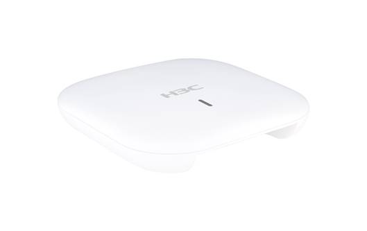
WA6126
Figure 1-1 WA6126
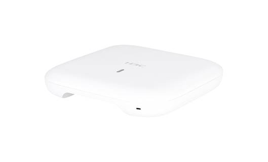
WA6526
Figure 1-2 WA6526
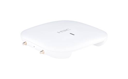
WA6526E
Figure 1-3 WA6526E
WA6528i
Figure 1-4 WA6528i
2 Technical specifications
WA6126
Table 2-1 Technical specifications for the WA6126
|
Item |
Description |
|
Dimensions (H × W × D) |
35 × 185 × 185 mm (1.38 × 7.28 × 7.28 in) |
|
Weight |
650 g (22.93 oz) |
|
Power consumption |
· Standby: 7 W · Operating: ¡ ≤ 17.6 W (USB excluded) ¡ ≤ 20.1 W (USB included) |
|
Antenna |
Built-in antenna |
|
Protocol |
· IEEE802.11a/b/g/n/ac/ax · IEEE802.3at |
WA6526
Table 2-2 Technical specifications for the WA6526
|
Item |
Description |
|
Dimensions (H × W × D) |
35 × 185 × 185 mm (1.38 × 7.28 × 7.28 in) |
|
Weight |
650 g (22.93 oz) |
|
Power consumption |
· Standby: 7 W · Operating: ¡ ≤ 17.6 W (USB excluded) ¡ ≤ 20.1 W (USB included) |
|
Antenna |
Built-in antenna |
|
Protocol |
· IEEE802.11a/b/g/n/ac/ax · IEEE802.3at |
WA6526E
Table 2-3 Technical specifications for the WA6526E
|
Item |
Description |
|
Dimensions (H × W × D) |
35 × 185 × 185 mm (1.38 × 7.28 × 7.28 in) |
|
Weight |
650 g (22.93 oz) |
|
Power consumption |
· Standby: 7 W · Operating: ¡ ≤ 17.6 W (not supplying power) ¡ ≤ 35.1 W (supplying power) |
|
Antenna |
External antenna |
|
Protocol |
· IEEE802.11a/b/g/n/ac/ax · IEEE802.3at |
WA6528i
Table 2-4 Technical specifications for the WA6528i
|
Item |
Description |
|
Dimensions (H × W × D) |
40 × 225 × 225 mm (1.57 × 8.86 × 8.86 in) |
|
Weight |
1050 g (37.04 oz) |
|
Power consumption |
· Standby: 10 W · Operating: ¡ ≤ 25 W (PoE_OUT/USB excluded) ¡ ≤ 42.5 W (PoE_OUT/USB included) |
|
Antenna |
Built-in smart antenna |
|
Protocol |
· IEEE802.11a/b/g/n/ac/ax · IEEE802.3at/bt |
3 Ports and LEDs
Ports
WA6126
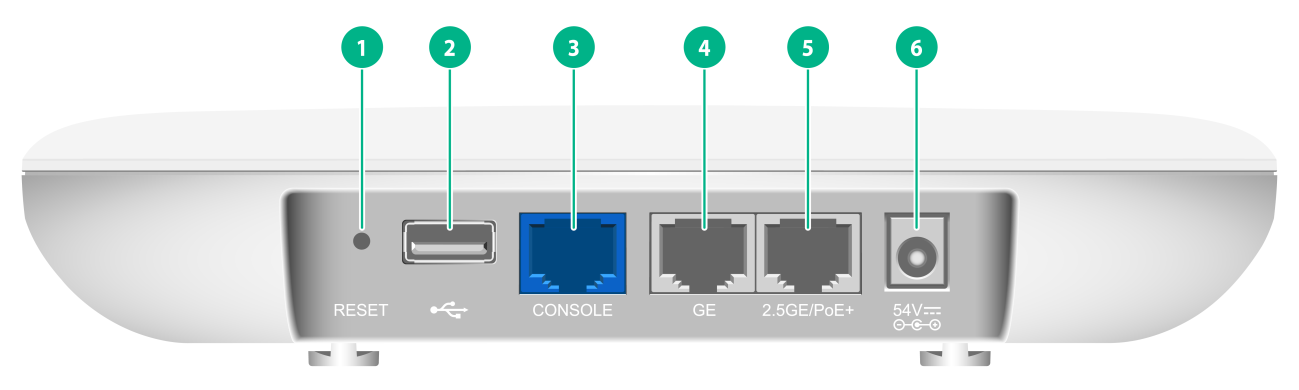
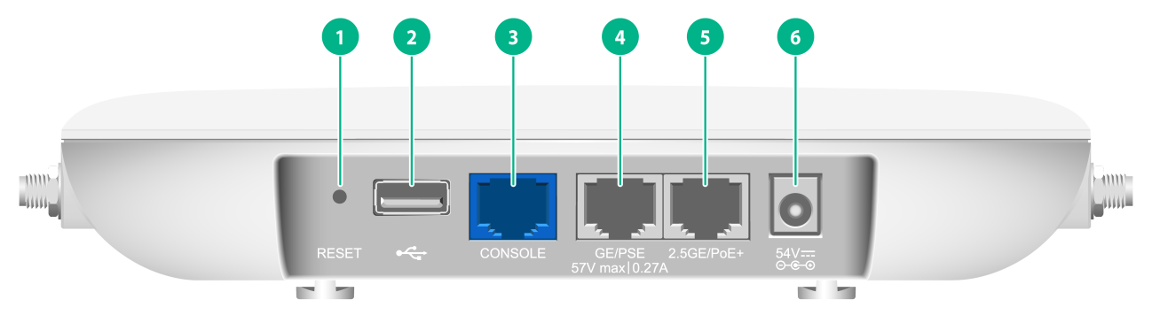
Figure 3-1 Ports on the WA6126 AP

|
(1) Reset button |
(2) USB port |
|
(3) Console port |
(4) 10/100/1000M Ethernet copper port |
|
(5) 100/1000/2500M Ethernet copper port |
(6) Power port |
Table 3-1 Port descriptions
|
Port |
Description |
|
Console port |
Used by technical personnel only for device configuration and management. |
|
2.5GE/PoE+ |
Used for connecting the AP to an uplink device for Internet or MAN access. It can also receive PoE power from the uplink device. When the AP operates in fit AP mode, the port is represented by interface number SGE1/0/1 in the MAP file and smartrate-Ethernet 1 for configuration on the AC. |
|
GE |
When the AP operates in fit AP mode, the port is represented by interface number GE1/0/1 in the MAP file and gigabitethernet 1 for configuration on the AC. |
|
USB port |
USB 3.0-compliant USB port. NOTE: By default, the USB port is disabled. To enable the USB port, execute the usb enable command in AP view. |
|
54V DC |
Used for receiving +54 VDC power from a local power source. |
|
RESET |
For more information, see Table 3-8. |
WA6526
Figure 3-2 Ports on the WA6526 AP
|
(1) Reset button |
(2) USB port |
|
(3) Console port |
(4) 10/100/1000M Ethernet copper port |
|
(5) 100/1000/2500M Ethernet copper port |
(6) Power port |
Table 3-2 Port descriptions
|
Port |
Description |
|
Console port |
Used by technical personnel only for device configuration and management. |
|
2.5GE/PoE+ |
Used for connecting the AP to an uplink device for Internet or MAN access. It can also receive PoE power from the uplink device. When the AP operates in fit AP mode, the port is represented by interface number SGE1/0/1 in the MAP file and smartrate-Ethernet 1 for configuration on the AC. |
|
GE |
When the AP operates in fit AP mode, the port is represented by interface number GE1/0/1 in the MAP file and gigabitethernet 1 for configuration on the AC. |
|
USB port |
USB 3.0-compliant USB port. NOTE: By default, the USB port is disabled. To enable the USB port, execute the usb enable command in AP view. |
|
54V DC |
Used for receiving +54 VDC power from a local power source. |
|
RESET |
For more information, see Table 3-8. |
WA6526E
Figure 3-3 Ports on the WA6526E AP (1)
|
(1) Reset button |
(2) USB port |
|
(3) Console port |
(4) 10/100/1000M Ethernet copper port |
|
(5) 100/1000/2500M Ethernet copper port |
(6) Power port |
Figure 3-4 Ports on the WA6526E AP (2)
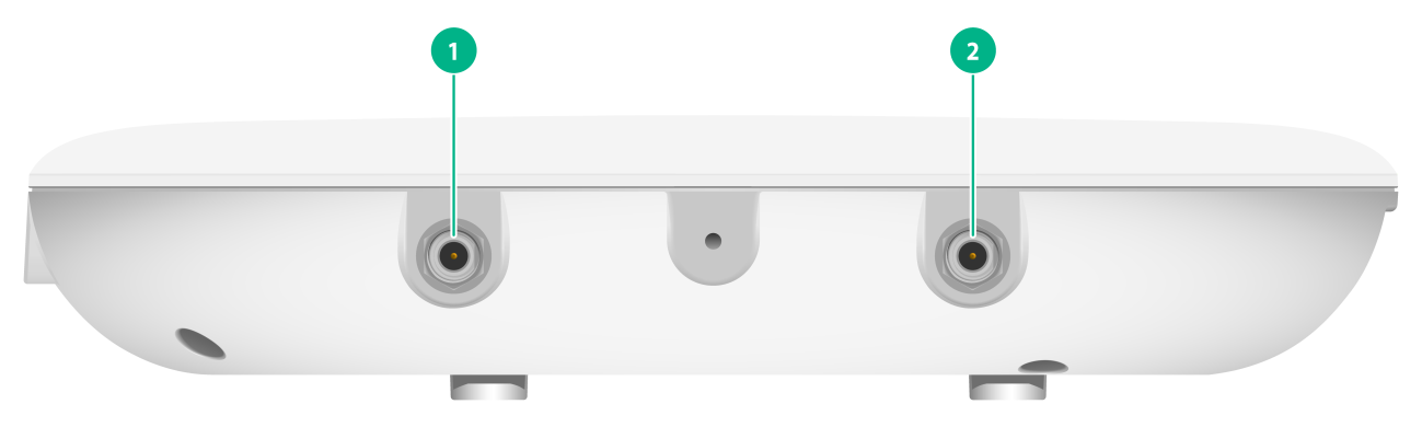
|
(1) and (2) ANT 1/2 connectors |
|
Figure 3-5 Ports on the WA6526E AP (3)
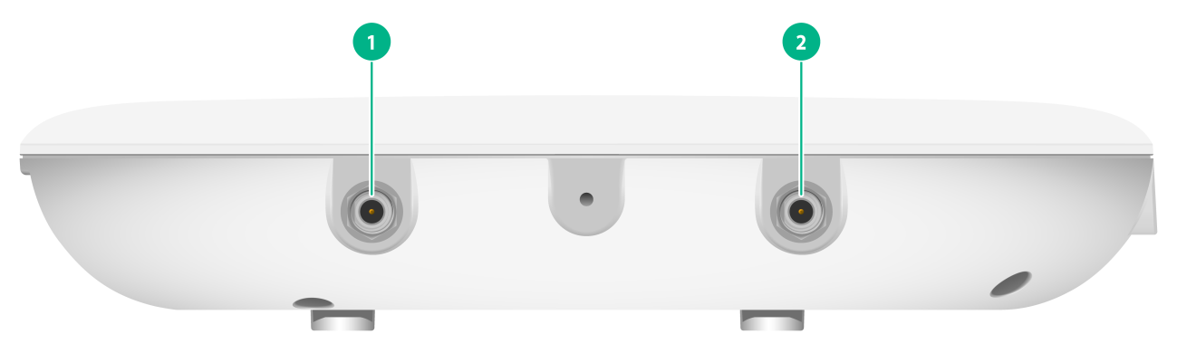
|
(1) and (2) ANT 3/4 connectors |
|
Table 3-3 Port descriptions
|
Port |
Description |
|
Console port |
Used by technical personnel only for device configuration and management. |
|
2.5GE/PoE+ |
Used for connecting the AP to an uplink device for Internet or MAN access. It can also receive PoE power from the uplink device. When the AP operates in fit AP mode, the port is represented by interface number SGE1/0/1 in the MAP file and smartrate-Ethernet 1 for configuration on the AC. |
|
GE/PSE |
Used for connecting the AP to a downlink device. The AP can supply power through this port to a device with a maximum power consumption of 15 W. When the AP operates in fit AP mode, the port is represented by interface number GE1/0/1 in the MAP file and gigabitethernet 1 for configuration on the AC. |
|
USB port |
USB 3.0-compliant USB port. |
|
54V DC |
Used for receiving +54 VDC power from a local power source. |
|
ANT 1/2/3/4 |
Used to connect feeder lines of antennas. |
|
RESET |
For more information, see Table 3-8. |
WA6528i
Figure 3-6 Ports on the WA6528i AP
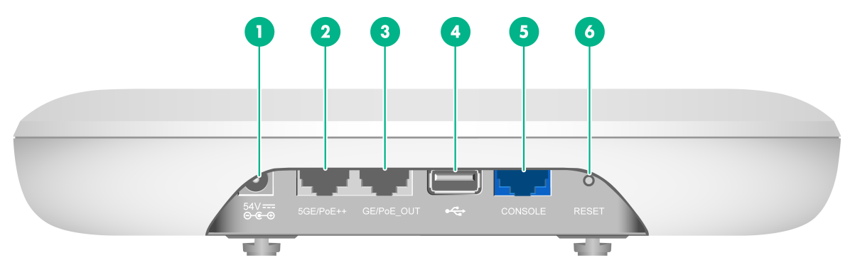
|
(1) Power port |
(2) 100/1000/2500/5000M Ethernet copper port |
|
(3) 10/100/1000M Ethernet copper port |
(4) USB port |
|
(5) Console port |
(6) Reset button |
Table 3-4 Port descriptions
|
Port |
Description |
|
Console port |
Used by technical personnel only for device configuration and management. |
|
5GE/PoE++ |
Used for connecting the AP to an uplink device for Internet or MAN access. It can also receive PoE power from the uplink device. When the AP operates in fit AP mode, the port is represented by interface number SGE1/0/1 in the MAP file and smartrate-Ethernet 1 for configuration on the AC. |
|
GE/PoE_OUT |
Used for connecting the AP to a downlink device. The AP can supply power through this port to a device with a maximum power consumption of 15 W. When the AP operates in fit AP mode, the port is represented by interface number GE1/0/1 in the MAP file and gigabitethernet 1 for configuration on the AC. |
|
USB port |
USB 3.0-compliant USB port. |
|
54V DC |
Used for receiving +54 VDC power from a local power source. |
|
RESET |
For more information, see Table 3-8. |
LEDs and buttons
The LED status varies by AP operating mode. For information about the supported operating modes, see the release notes for the AP.
Table 3-5 LED descriptions (fit AP mode)
|
LED status |
Description |
||
|
Off |
No power is present or the LED has been turned off. |
||
|
Yellow |
Steady on |
The AP is initializing, or an initialization exception has occurred. |
|
|
Flashing (twice per second) |
The Ethernet interfaces are down and no mesh links are established. |
||
|
Green |
Steady on |
The AP has registered to an AC, but does not have any associated clients. |
|
|
Flashing (once per two seconds) |
The AP has started up but has not registered to any AC. |
||
|
Flashing (twice per second) |
The AP is upgrading the image. |
||
|
Blue |
Flashing (once per second) |
The radios have associated clients. |
|
Table 3-6 LED descriptions (cloud mode)
|
LED status |
Description |
||
|
Off |
No power is present or the LED has been turned off. |
||
|
Yellow |
Steady on |
The AP is initializing, or an initialization exception has occurred. |
|
|
Flashing (twice per second) |
The Ethernet interfaces are down and no mesh links are established. |
||
|
Green |
Steady on |
The AP is in standby state and has connected to the Cloudnet platform, but does not have any associated clients. |
|
|
Flashing (once per second) |
The AP has connected to the Cloudnet platform and has associated clients. |
||
|
Flashing (twice per second) |
The AP is upgrading the image. |
||
|
Blue |
Steady on |
The AP is in standby state, but has not connected to the Cloudnet platform and does not have associated clients. |
|
|
Flashing (once per second) |
The AP has not connected to the Cloudnet platform, but has associated clients. |
||
Table 3-7 LED descriptions (anchor AC mode)
|
LED status |
Description |
||
|
Off |
No power is present or the LED has been turned off. |
||
|
Yellow |
Steady on |
The AP is initializing, or an initialization exception has occurred. |
|
|
Flashing (twice per second) |
The Ethernet interfaces are down and no mesh links are established. |
||
|
Green |
Steady on |
The AP has started up and is in standby state, but does not have any associated clients. |
|
|
Flashing (twice per second) |
The AP is upgrading the image. |
||
|
Blue |
Flashing (once per second) |
The AP has associated clients. |
|
Table 3-8 RESET button descriptions
|
Press and hold duration (sec) |
Button LED status |
Description |
|
|
0 to 5 |
Steady green |
Reset the AP. |
|
|
5 to 20 |
Flashing green (twice per second) |
Restore to the factory defaults. |
|
|
20 to 30 |
Yellow |
Flashing (once per two seconds) |
The AP is operating in fit AP mode. NOTE: The system will change the operating mode to cloud if you press and hold the button until the LED flashes green four times per second. |
|
Flashing (twice per second) |
The AP is operating in anchor AC mode. |
||
|
Flashing (four times per second) |
The AP is operating in cloud mode. |
||
|
> 30 |
Yellow |
Flashing (twice per second) |
The AP is operating in anchor AC mode. |
|
Flashing (four times per second) |
The AP is operating in cloud mode. |
||
|
Green |
Flashing (four times per second) |
Change the AP operating mode to cloud. NOTE: If you release the button, the AP will restart for the new mode to take effect. |
|
