- Table of Contents
- Related Documents
-
| Title | Size | Download |
|---|---|---|
| 01-Installation Guide | 1.16 MB |
General safety recommendations
Determining the installation position
Connecting the AP to a power source
Connecting a local power source
Logging in to the AP from the console port
Connecting the AP to a configuration terminal from the console port
Setting parameters for the configuration terminal
Logging in to the AP through Telnet
Logging in from the Web interface
4 Configuring the AP from the Cloudnet platform
Downloading and installing Cloudnet App Int
Logging in to the Cloudnet platform
1 Preparing for installation
Safety recommendations
Safety labels
|
Safety label |
Description |
|
|
Hot surface warning label. A device attached with this label might have a hot surface during operation. Install the device in a restricted access location. Only servicing engineers or trained personnel can operate the devices in the access location. |
General safety recommendations
|
|
WARNING! Only professional technical personnel can install and remove the AP and its accessories. You must read all safety instructions carefully before working with the AP. |
To avoid possible bodily injury and equipment damage, read the following safety recommendations before installing the AP. Note that the recommendations do not cover every possible hazardous condition.
· To avoid bodily injury and device damage, take adequate safety measures.
· Place the AP in a dry and flat location and take anti-slip measures.
· Keep the AP clean and dust-free.
· Do not place the AP in a moist area and avoid liquid intrusion.
· Keep the AP and installation tools away from walkways.
Site preparation
Before installing the AP, examine the installation site and make sure the AP will operate in a favorable environment. Make sure the temperature, humidity, and altitude at the installation site meet the requirements in Table 1-1.
Table 1-1 Temperature, humidity, and altitude requirements
|
Item |
Specification |
|
Operating temperature |
–10°C to +55°C (32°F to 113°F) |
|
Operating humidity |
5% RH to 95% RH, noncondensing |
|
Operating altitude |
–60 m to +5000 m (–196.85 ft to +16404.20 ft) |
Installation accessories
Figure 1-1 Accessories provided with the AP
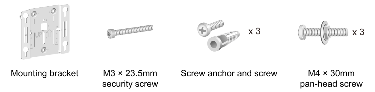
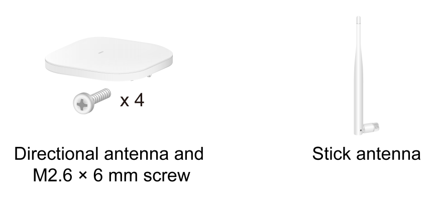
Figure 1-2 Optional accessories for the WA6526E
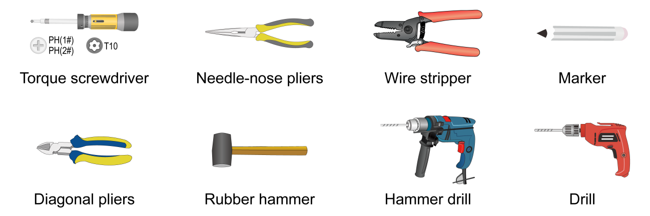
Installation tools
When installing the AP, you might need the following tools. Prepare the installation tools yourself as required.
Figure 1-3 Installation tools
2 Installing the AP
Installation flowchart
Figure 2-1 Installation flowchart
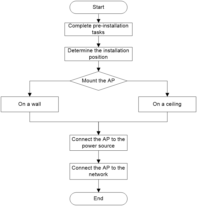
Pre-installation tasks
Before installing the AP, perform the following tasks:
· Connect the AP to a power source and the network. Examine the LEDs to verify that the AP is operating correctly. For information about AP LEDs, see ports and LEDs in Hardware Information and Specifications.
· Record the MAC address and serial number at the rear of the AP for future use.
· Make sure you have completed cabling at the installation site.
· If the Ethernet interface rate is 2.5 or 5 Gbps, use Cat-5e or above network cables. For information about the supported interface rates, see technical specifications in Hardware Information and Specifications.
· The AP is typically installed on a high position. As a best practice, access and configure the AP before installing it.
· If a cable is routed outdoors, make sure a lighting arrester is attached to the AP port. Prepare a lighting arrester yourself as needed.
Determining the installation position
Determine the installation position by observing the following principles:
· Few obstacles such as wall exist between the AP and clients.
· The AP is far away from electronic devices (such as microwave oven) that might generate radio frequency (RF) noise.
· The AP does not hinder people’s daily work and life.
· The place is not water seeping, water soaking, and condensing.
Mounting the AP
|
|
IMPORTANT: · Before mounting the AP on a wall or ceiling, connect cables to the AP. · Install an M3 × 23.5 security screw as required. |
The AP can be installed only indoors. You can mount the AP on a wall or a ceiling.
APs and the mounting bracket
Figure 2-1 WA6126 AP
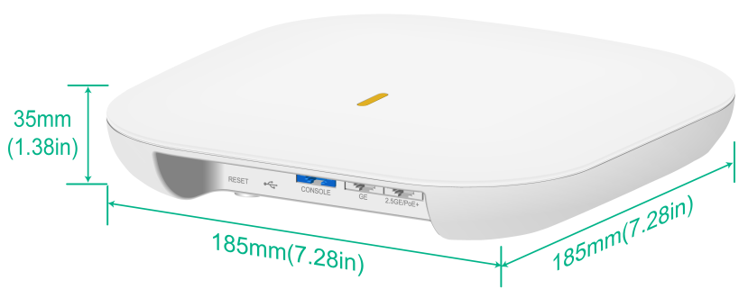
Figure 2-2 WA6526 AP

Figure 2-3 WA6526E AP
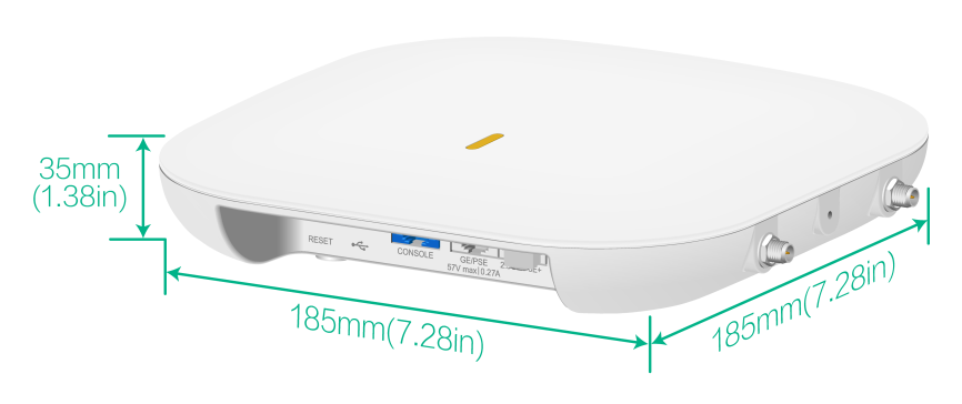
Figure 2-4 WA6528i AP
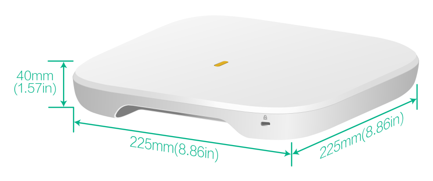
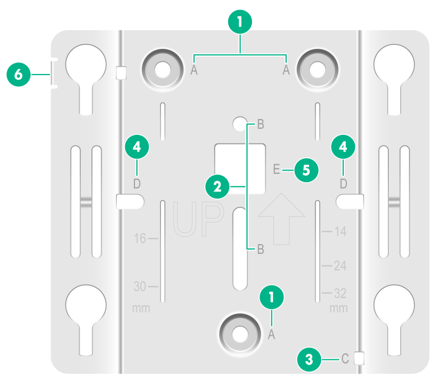
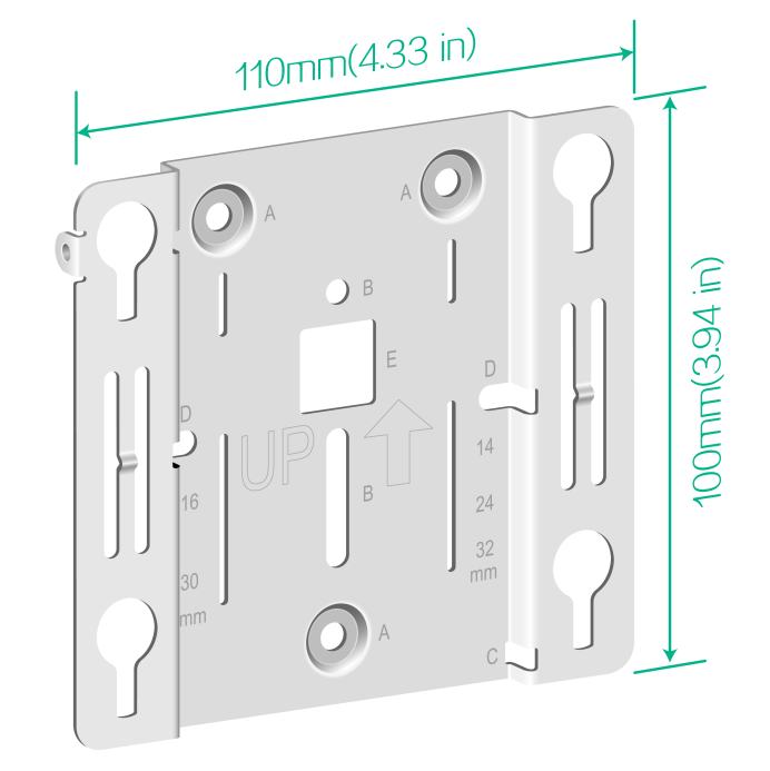
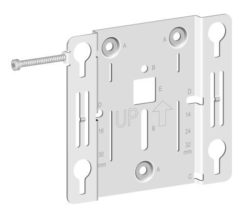
Figure 2-5 Mounting bracket
|
(1) Installation hole for securing the mounting bracket to a wall or ceiling (point A) |
|
(2) T-rail installation hole (reserved)(point B) |
|
(3) Auxiliary hole for securing cables by using cable tie (point C) |
|
(4) Installation hole reserved for electrical outlet box installation (point D) |
|
(5) Auxiliary hole for threading a cable to connect to the AP (point E) |
|
(6) Security hole for an M3 × 23.5 security screw |
Figure 2-6 Mounting bracket dimensions
Installing antennas
Only the WA6526E supports external antennas. Install a directional antenna or stick antennas as needed.
To install a directional antenna, put the antenna over the AP front, use M2.6 × 6 mm screws to secure the antenna, and then connect the SMA connectors on the antenna to the R-SMA connectors on the AP. See Figure 2-7.
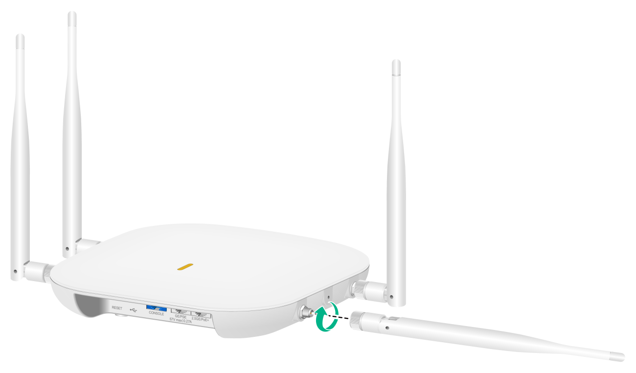
To install a stick antenna, attach the antenna to an R-SMA connector on the AP. See Figure 2-8.
Figure 2-7 Installing a directional antenna
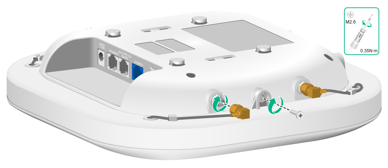
Figure 2-8 Installing stick antennas
Mounting the AP on a wall
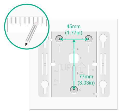
1. Place the mounting bracket against the wall and mark the installation holes on the wall.
Figure 2-9 Marking the installation holes on the wall
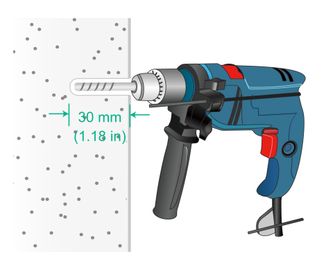
2. Drill three holes with a diameter of 6 mm (0.24 in) and a depth of 30 mm (1.18 in) at the marked locations, as shown in Figure 2-10.
Figure 2-10 Drilling holes in the wall
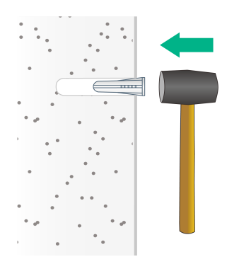
3. Insert a screw anchor into each hole, and tap the screw anchor with a rubber hammer until it is all flush with the wall surface, as shown in Figure 2-11.
Figure 2-11 Hammering the screw anchor into the wall
4. Thread the M3 × 23.5 security screw through the security hole in the mounting bracket. Make sure the screw does not block the keyhole slot.
Figure 2-12 Inserting the security screw
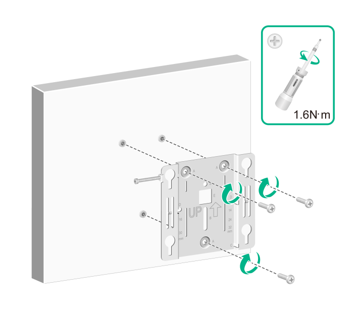
5. Insert the screws through the installation holes in the mounting bracket into the holes in the wall. Fasten the screws to secure the mounting bracket to the wall, as shown in Figure 2-13.
Figure 2-13 Attaching the mounting bracket to the wall
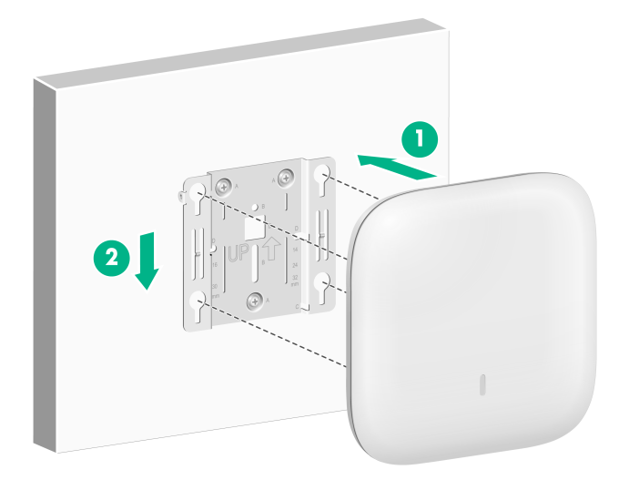
6. Position the four pegs at the AP rear into the keyhole slots in the mounting bracket and then slide the AP down until it sits securely in the keyhole slots, as shown in Figure 2-14.
Figure 2-14 Attaching the AP to the mounting bracket
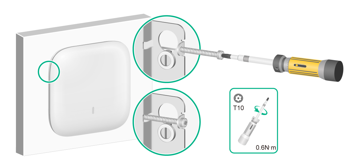
7. Use a security Torx screwdriver to fasten the M3 × 23.5 security screw.
Figure 2-15 Fastening the M3 × 23.5 security screw
Mounting the AP on a ceiling
|
|
CAUTION: The ceiling for installing the AP must be less than 18 mm (0.71 in) in thickness, and can bear a load of 5 kg (11.02 lb). If you must install the AP on a ceiling not strong enough, use boards to reinforce the ceiling. |
The installation method for the M3 × 23.5 security screw is similar when the AP is mounted on the wall and on the ceiling.
To mount the AP on a ceiling:
1. Remove the ceiling tile.
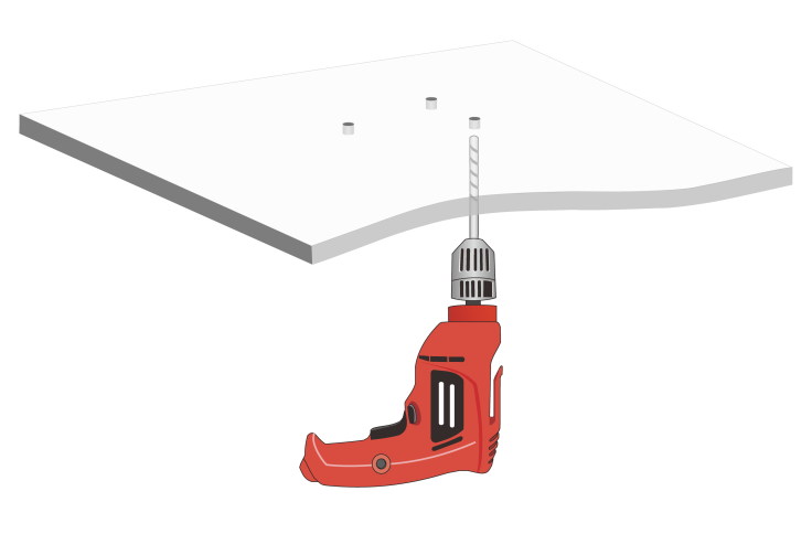
2. Place the mounting bracket against the ceiling tile and mark the installation holes on the ceiling tile. Drill three holes with a diameter of 6 mm (0.24 in) at the marked positions, as shown in Figure 2-16.
Figure 2-16 Drilling holes in the ceiling tile
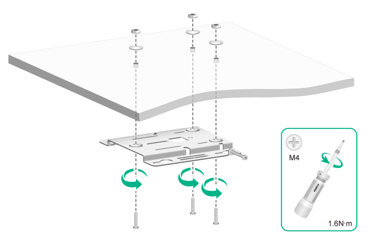
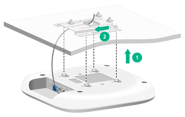
3. Thread the pan-head screws through the installation holes in the mounting bracket and into the holes in the ceiling tile. Fasten washers and nuts at the other side of the ceiling to secure the mounting bracket to the ceiling, as shown in Figure 2-17.
Figure 2-17 Attaching the mounting bracket to the ceiling
4. Connect a cable to the AP. Then position the four pegs at the AP rear into the keyhole slots in the mounting bracket and slide the AP until it sits securely in the keyhole slots.
Figure 2-18 Attaching the AP to the mounting bracket
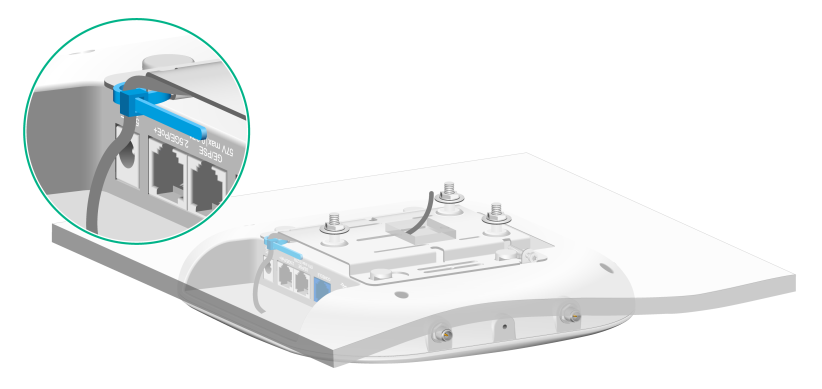
(Optional.) You can use a cable tie to secure the cable before attaching the AP to the mounting bracket. First thread the cable tie through the auxiliary hole in the mounting bracket, leaving the cable tie unfastened, and then adjust the cable length and fasten the cable tie to secure the cable.
No cable tie is provided with the AP. Prepare one yourself as required.
Figure 2-19 Using a cable tie to secure the cable
5. Verify that the AP is installed securely to prevent it from falling off.
Connecting the AP to a power source
You can supply power to the AP by using a local power source or through PoE as required. Before powering the AP, make sure the local power source or the power sourcing equipment (PSE) is reliably grounded.
Connecting a PoE power source
To power the AP through PoE, use an Ethernet cable to connect an Ethernet port on a PoE switch to the GE port on the AP.
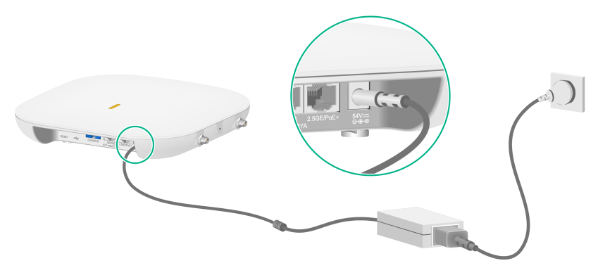
Connecting a local power source
You can use an AC/DC power adapter to connect the AP to a local power source. No power adapter is provided with the AP. Purchase a power adapter from H3C as required. Table 2-1 describes the power adapter specifications.
Table 2-1 Power adapter specifications
|
Item |
Specification |
|
Input |
100 VAC to 240 VAC |
|
Output |
+48 VDC to +55 VDC |
Figure 2-20 Using a power adapter to connect the AP to a local power source
Check after power-on
Examine the LEDs on the AP after you power on it to verify that the AP is operating correctly. For more information about the LEDs, see ports and LEDs in Hardware Information and Specifications.
3 Accessing the AP
Wi-Fi 6 APs of version 2442 or above allow users to switch the working mode (cloud, anchor AC, or AP) without obtaining the corresponding image file. For more information about the supported working modes, see the release notes for the AP.
When the AP operates in cloud or anchor AC mode, you can access and configure the AP from the console port, Web interface, or through Telnet. Accessing the AP from the Web interface or through Telnet requires the IP address of the AP.
Logging in to the AP from the console port
Prepare the following items for accessing the device from the console port:
· An 8-core console cable, with a crimped RJ-45 connector at one end, and a DB-9 connector at the other end.
· A configuration terminal. It can be a standard character terminal with an RS-232 port, or a PC.
Connecting the AP to a configuration terminal from the console port
|
|
CAUTION: · To connect a PC to the AP, first connect the PC end. To disconnect a PC from the AP, first disconnect the AP end. · If the PC does not have an RS-232 port but a USB port, use a USB-to-RS-232 converter to connect the USB port to the console cable and install the driver on the PC. |
To connect the AP to a configuration terminal from the console port:
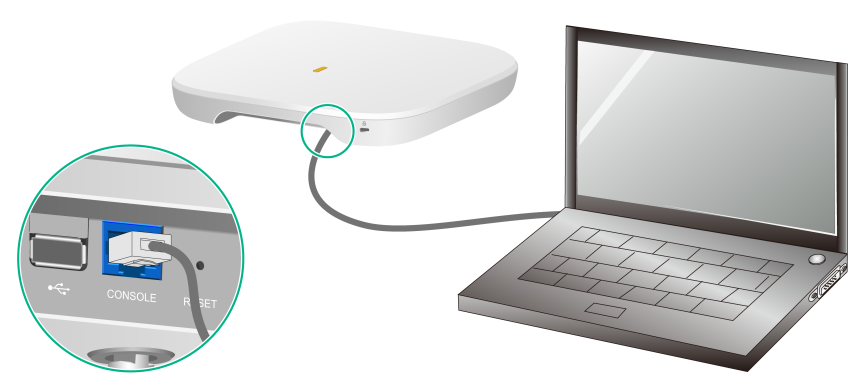
1. Connect the DB-9 connector of the console cable to the serial port on the configuration terminal, for example, a PC.
2. Connect the RJ-45 connector of the console cable to the console port on the AP.
Figure 3-1 Connecting the AP to a PC from the console port
Setting parameters for the configuration terminal
To configure and manage the AP from the console port, you must run a terminal emulator program, such as HyperTerminal or PuTTY, on your configuration terminal. You can use the emulator program to connect a network device, a Telnet site, or an SSH site. For more information about the terminal emulator programs, see the user guides for these programs.
Configure the terminal parameters as follows:
· Bits per second—9,600.
· Data bits—8.
· Stop bits—1.
· Parity—None.
· Flow control—None.
Procedure
Verify that the AP is connected correctly to the configuration terminal and the configuration terminal parameters are configured correctly. Then, power on the AP. You can see the following information on the configuration terminal:
System is starting...
Booting Normal Extend BootWare.
……
System application is starting...
Startup configuration file does not exist.
User interface con0 is available.
Press ENTER to get started.
Logging in to the AP through Telnet
By default, Telnet is enabled and the following login information is defined for your login:
· Username—admin.
· Password—h3capadmin.
Cloud mode
Make sure the PC obtains an IP address dynamically.
When the AP operates in cloud mode, it obtains the IP address of VLAN 1 dynamically by default.
Some Intel wireless adapters do not support 802.11ax. For clients to detect Wi-Fi 6 networks, upgrade the driver for the wireless adapter to the most recent version. For more information, see the official statement of Intel.
To log in to the AP through a wireless connection:
1. Enable WLAN on the configuration terminal and access WLAN H3C_xxxxxx, where xxxxxx is the last six bits of the AP's MAC address.
2. Enter telnet wlan.h3c.com from the CLI of the terminal.
3. Enter the default username and password and change the default password as prompted.
Anchor ACmode
Make sure the PC and AP are on the same network.
To log in to the AP through a wired connection:
1. Enter the default IP address for accessing the device through Telnet: 192.168.0.50. If the default IP address has been changed, contact the administrator to get the new IP address.
2. Enter the default username and password and change the default password as prompted.
Logging in from the Web interface
By default, HTTP and HTTPS are enabled and the following login information is defined for your login:
· Username—admin.
· Password—h3capadmin.
Cloud mode
Make sure the PC obtains an IP address dynamically.
When the AP operates in cloud mode, it obtains the IP address of VLAN 1 dynamically by default.
Some Intel wireless adapters do not support 802.11ax. For clients to detect Wi-Fi 6 networks, upgrade the driver for the wireless adapter to the most recent version. For more information, see the official statement of Intel.
To log in to the AP through a wireless connection:
1. Enable WLAN on the configuration terminal and access WLAN H3C_xxxxxx, where xxxxxx is the last six bits of the AP's MAC address.
2. Visit http://wlan.h3c.com from a browser, and then press Enter.
Visit http://myap.h3c.com from a browser for a configuration terminal in a version earlier than 2448P10.
3. Enter the default username and password. For security purposes, change the password as prompted after you access the Web interface, and then click OK.
Anchor ACmode
Make sure the PC and AP are on the same network.
To log in to the AP from the Web interface:
1. Enter the default IP address for accessing the device from the Web interface: 192.168.0.50. If the default IP address has been changed, contact the administrator to get the new IP address.
2. Enter the default username and password, and then click Log In. Change the default password as prompted, and then click OK.
4 Configuring the AP from the Cloudnet platform
You can manage the AP remotely from the Cloudnet platform (Web interface or app) only when the AP operates in cloud mode.
Downloading and installing Cloudnet App Int
Make sure the smartphone uses Android 4.0, iOS7.0, or a higher-version operating system.
Download and install Cloudnet App Int from Google Play Store.
Logging in to the Cloudnet platform
To manage the AP from the Cloudnet platform, make sure the AP uses an IP address that can reach the external network.
To log in to the Cloudnet platform:
1. Open Cloudnet App Int or visit https://oasiscloudnet.h3c.com from a browser.
2. Enter the username and password.
After login, you can add the AP to the platform and manage the AP. For more information about platform login and device management, see H3C Cloudnet Deployment Guide.
