- Table of Contents
-
- 06-Layer 3—IP Services Configuration Guide
- 00-Preface
- 01-ARP configuration
- 02-IP addressing configuration
- 03-DNS configuration
- 04-mDNS relay configuration
- 05-IP forwarding basics configuration
- 06-Fast forwarding configuration
- 07-Adjacency table configuration
- 08-IRDP configuration
- 09-IP performance optimization configuration
- 10-UDP helper configuration
- 11-IPv6 basics configuration
- 12-IPv6 fast forwarding configuration
- 13-AFT configuration
- 14-Tunneling configuration
- 15-GRE configuration
- 16-ADVPN configuration
- 17-HTTP redirect configuration
- Related Documents
-
| Title | Size | Download |
|---|---|---|
| 13-AFT configuration | 322.97 KB |
Content
Configuring an IPv6-to-IPv4 destination address translation policy
About IPv6-to-IPv4 destination address translation policies
Configuring an IPv4-to-IPv6 source address static mapping
Configuring an IPv6-to-IPv4 source address translation policy
About IPv6-to-IPv4 source address translation policies
Configuring an IPv6-to-IPv4 source address static mapping
Configuring an IPv6-to-IPv4 source address dynamic translation policy
Configuring an IPv4-to-IPv6 destination address translation policy
About IPv4-to-IPv6 destination address translation policies
Configuring an AFT mapping for an IPv6 internal server
Configuring an IPv6-to-IPv4 source address static mapping
Configuring an IPv4-to-IPv6 destination address translation policy based on IVI or general prefix
Configuring an IPv4-to-IPv6 source address translation policy
About IPv4-to-IPv6 source address translation policies
Configuring an IPv4-to-IPv6 source address static mapping
Configuring an IPv4-to-IPv6 source address translation policy based on NAT64 or general prefix
Setting the ToS field to 0 for translated IPv4 packets
Setting the Traffic Class field to 0 for translated IPv6 packets
Specifying a failover group for dynamic AFT
Configuring AFT in a CP-UP separation scenario
About AFT in a CP-UP separation scenario
Display and maintenance commands for AFT
AFT configuration examples (in non-CGN scenarios)
Example: Allowing IPv4 Internet access from an IPv6 network
Example: Providing FTP service from an IPv6 network to the IPv4 Internet
Example: Allowing mutual access between IPv4 and IPv6 networks
Example: Allowing IPv6 Internet access from an IPv4 network
Example: Providing FTP service from an IPv4 network to the IPv6 Internet
AFT configuration examples (in CGN scenarios)
Example: Allowing IPv4 Internet access from an IPv6 network
Example: Allowing IPv4 Internet access from an IPv6 network in a CP-UP separation scenario
Configuring AFT
About AFT
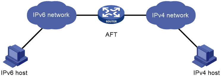
Address Family Translation (AFT) translates an IP address of one address family into an IP address of the other address family. It enables an IPv4 network and an IPv6 network to communicate with each other, as shown in Figure 1. The IPv4 host and the IPv6 host can communicate with each other without changing the existing configuration.
Figure 1 AFT application scenario
AFT translation methods
Static AFT
Static AFT creates a fixed mapping between an IPv4 address and an IPv6 address.
To perform static AFT, you can configure IPv4-to-IPv6 source address static translation policies and IPv6-to-IPv4 source address static translation policies.
An IPv4-to-IPv6 source address static translation policy can be applied to the following scenarios:
· For an IPv4-initiated session packet, if the source IPv4 address in the packet matches the translation policy, AFT translates the source IPv4 address in the packet to the specified IPv6 address.
· For an IPv6-initiated session packet, if the destination IPv6 address in the packet matches the translation policy, AFT translates the destination IPv6 address in the packet to the specified IPv4 address.
An IPv6-to-IPv4 source address static translation policy can be applied to the following scenarios:
· For an IPv6-initiated session packet, if the source IPv6 address in the packet matches the translation policy, AFT translates the source IPv6 address in the packet to the specified IPv4 address.
· For an IPv4-initiated session packet, if the destination IPv4 address in the packet matches the translation policy, AFT translates the destination IPv4 address in the packet to the specified IPv6 address.
Dynamic AFT
Dynamic AFT creates a dynamic mapping between an IPv4 address and an IPv6 address.
When dynamic AFT performs IPv6-to-IPv4 source address translation, the Not Port Address Translation (NO-PAT) and Port Address Translation (PAT) modes are available.
NO-PAT
NO-PAT translates one IPv6 address to one IPv4 address. An IPv4 address assigned to one IPv6 host cannot be used by any other IPv6 host until it is released.
NO-PAT supports all IP packets.
PAT
PAT translates multiple IPv6 addresses to a single IPv4 address by mapping each IPv6 address and port to the IPv4 address and a unique port. PAT supports the following packet types:
· TCP packets.
· UDP packets.
· ICMPv6 echo request and echo reply messages.
PAT supports port blocks for connection limit and user tracing. Port blocks are generated by dividing the port range by the port block size. Port block-based PAT maps multiple IPv6 addresses to one IPv4 address and uses a port block for each IPv6 address.
Port block-based PAT functions as follows:
1. When an IPv6 host first initiates a connection to the IPv4 network, it creates a mapping from the host's IPv6 address to an IPv4 address and a port block.
2. It translates the IPv6 address to the IPv4 address, and the source ports to ports in the port block for subsequent connections from the IPv6 host until the ports in the port block are exhausted.
|
|
NOTE: If the port range cannot be divided by the port block size exactly, the remaining ports are not used for translation. |
Prefix translation
NAT64 prefix translation
NAT64 prefix is an IPv6 address prefix used to construct an IPv6 address representing an IPv4 node in an IPv6 network. The IPv6 hosts do not use a constructed IPv6 address as their real IP address. The length of a NAT64 prefix can be 32, 40, 48, 56, 64, or 96.
As shown in Figure 2, the construction methods vary depending on the NAT64 prefix length. Bits 64 through 71 in the constructed IPv6 address are reserved bits, which must be set to 0.
· If the prefix length is 32, 64, or 96 bits, the IPv4 address contained in the IPv6 address will be intact.
· If the prefix length is 40, 48, or 56 bits, the IPv4 address contained in the IPv6 address will be divided into two parts by bits 64 through 71.
Figure 2 IPv6 address construction with NAT 64 prefix and IPv4 address
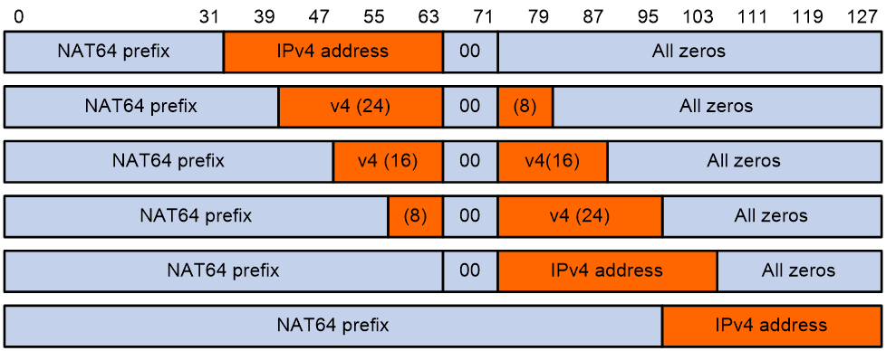
Table 1 Examples of IPv6 address construction with NAT64 prefix and IPv4 address
|
IPv6 prefix |
IPv4 address |
Constructed IPv6 address |
|
2001:db8::/32 |
192.0.2.33 |
2001:db8:c000:221:: |
|
2001:db8:100::/40 |
192.0.2.33 |
2001:db8:1c0:2:21:: |
|
2001:db8:122::/48 |
192.0.2.33 |
2001:db8:122:c000:2:2100:: |
|
2001:db8:122:300::/56 |
192.0.2.33 |
2001:db8:122:3c0:0:221:: |
|
2001:db8:122:344::/64 |
192.0.2.33 |
2001:db8:122:344:c0:2:2100:: |
|
2001:db8:122:344::/96 |
192.0.2.33 |
2001:db8:122:344::192.0.2.33 |
AFT uses a NAT64 prefix to perform the following translation:
· IPv4-to-IPv6 source address translation. AFT translates a source IPv4 address to an IPv6 address that is created by using the NAT64 prefix and the IPv4 address.
· IPv6-to-IPv4 destination address translation. AFT uses the NAT64 prefix to match destination IPv6 addresses and extracts the embedded IPv4 address from matching IPv6 addresses.
A NAT64 prefix cannot be on the same subnet as any interface on the device.
IVI prefix translation
An IVI prefix is a 32-bit IPv6 address prefix. An IVI address is the IPv6 address that an IPv6 node uses. As shown in Figure 3, the IVI address includes an IVI prefix and an IPv4 address.
![]()
AFT uses an IVI prefix for IPv6-to-IPv4 source address translation. If a source IPv6 address matches the IVI prefix, AFT translates it to the embedded IPv4 address.
General prefix translation
A general prefix is an IPv6 address prefix used to construct an IPv6 address representing an IPv4 node in an IPv6 network. The length of a general prefix can be 32, 40, 48, 56, 64, or 96.
As shown in Figure 4, a general prefix based IPv6 address does not have bits 64 through 71 reserved as a NAT64 prefix based IPv6 address does. An IPv4 address is embedded as a whole into an IPv6 address.
Figure 4 General prefix based IPv6 address format
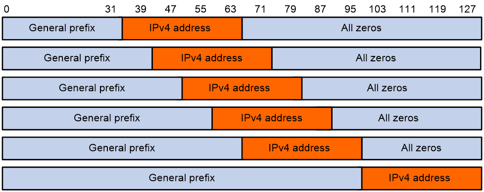
AFT uses a general prefix for IPv6-to-IPv4 source and destination address translation. If a source or destination IPv6 address matches the general prefix, AFT translates it to the embedded IPv4 address.
A general prefix cannot be on the same subnet as any interface on the device.
AFT internal server
AFT internal server maps an IPv4 address and port number to the IPv6 address and port number of an IPv6 internal server. It allows the IPv6 internal server to provide services to IPv4 hosts.
AFT translation process
The address translation differs for IPv6-initiated communication and IPv4-initiated communication.
IPv6-initiated communication
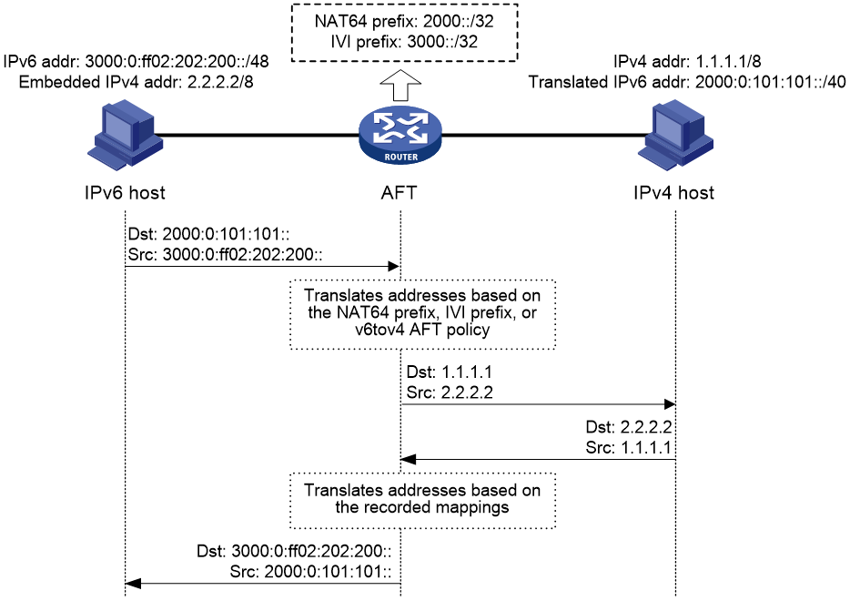
As shown in Figure 5, when the IPv6 host initiates access to the IPv4 host, AFT operates as follows:
1. Upon receiving a packet from the IPv6 host, AFT compares the packet with IPv6-to-IPv4 destination address translation policies.
¡ If a matching policy is found, AFT translates the destination IPv6 address according to the policy.
¡ If no matching policy is found, AFT does not process the packet.
2. AFT performs pre-lookup to determine the output interface for the translated packet. PBR is not used for the pre-lookup.
¡ If a matching route is found, the process goes to step 3.
¡ If no matching route is found, AFT discards the packet.
3. AFT compares the source IPv6 address of the packet with IPv6-to-IPv4 source address translation policies.
¡ If a matching policy is found, AFT translates the source IPv6 address according to the policy.
¡ If no matching policy is found, AFT discards the packet.
4. AFT forwards the translated packet and records the mappings between IPv6 addresses and IPv4 addresses.
5. AFT translates the IPv4 addresses in the response packet header to IPv6 addresses based on the address mappings before packet forwarding.
For more information about IPv6-to-IPv4 destination address translation policies, see "Configuring an IPv6-to-IPv4 destination address translation policy."
For more information about IPv6-to-IPv4 source address translation policies, see "Configuring an IPv6-to-IPv4 source address translation policy."
Figure 5 AFT process for IPv6-initiated communication
IPv4-initiated communication
As shown in Figure 6, when the IPv4 host initiates access to the IPv6 host, AFT operates as follows:
1. Upon receiving a packet from the IPv4 host, AFT compares the packet with IPv4-to-IPv6 destination address translation policies.
¡ If a matching policy is found, AFT translates the destination IPv4 address according to the policy.
¡ If no matching policy is found, AFT does not perform address translation.
2. AFT performs the pre-lookup to determine output interface for the translated packet. PBR is not used for the pre-lookup.
¡ If a matching route is found, the process goes to step 3.
¡ If no matching route is found, AFT discards the packet.
3. AFT compares the source IPv4 address with IPv4-to-IPv6 source address translation policies.
¡ If a matching policy is found, AFT translates the source IPv4 address according to the policy.
¡ If no matching policy is found, AFT discards the packet.
4. AFT forwards the translated packet and records the mappings between IPv4 addresses and IPv6 addresses.
5. AFT translates the IPv6 addresses in the response packet header to IPv4 addresses based on the address mappings before packet forwarding.
For more information about IPv4-to-IPv6 destination address translation policies, see "Configuring an IPv4-to-IPv6 destination address translation policy."
For more information about IPv4-to-IPv6 source address translation policies, see "Configuring an IPv4-to-IPv6 source address translation policy."
Figure 6 AFT process for IPv4-initiated communication

AFT ALG
AFT ALG translates address or port information in the application layer payloads.
For example, an FTP application includes a data connection and a control connection. The IP address and port number for the data connection depend on the payload information of the control connection. This requires AFT ALG to translate the address and port information.
AFT ALG supports the following protocol packets: FTP packets, DNS packets, HTTP packets, and ICMP error messages.
AFT tasks at a glance
To configure AFT, perform the following tasks:
1. Enabling AFT
2. Configuring address translation for IPv6-initiated communication
¡ Configuring an IPv6-to-IPv4 destination address translation policy
¡ Configuring an IPv6-to-IPv4 source address translation policy
¡ (Optional.) Setting the ToS field to 0 for translated IPv4 packets
3. Configuring address translation for IPv4-initiated communication
¡ Configuring an IPv4-to-IPv6 destination address translation policy
¡ Configuring an IPv4-to-IPv6 source address translation policy
¡ (Optional.) Setting the Traffic Class field to 0 for translated IPv6 packets
4. Specifying a failover group for dynamic AFT
This task is required if a CGN card is installed to implement AFT.
5. (Optional.) Configuring AFT logging
Enabling AFT
Restrictions and guidelines
To implement address translation between IPv4 and IPv6 networks, you must enable AFT on interfaces connected to the IPv4 network and interfaces connected to the IPv6 network.
Procedure
1. Enter system view.
system-view
2. Enter interface view.
interface interface-type interface-number
3. Enable AFT.
aft enable
By default, AFT is disabled.
Configuring an IPv6-to-IPv4 destination address translation policy
About IPv6-to-IPv4 destination address translation policies
AFT compares an IPv6 packet with IPv6-to-IPv4 destination address translation policies in the following order:
1. IPv4-to-IPv6 source address static mappings.
2. General prefixes.
3. NAT64 prefixes.
Configuring an IPv4-to-IPv6 source address static mapping
Restrictions and guidelines
An IPv4-to-IPv6 source address static translation policy creates a one-to-one mapping between an IPv4 address and an IPv6 address, and can be applied to the following scenarios:
· For an IPv4-initiated session packet, if the source IPv4 address in the packet matches the translation policy, AFT translates the source IPv4 address in the packet to the specified IPv6 address.
· For an IPv6-initiated session packet, if the destination IPv6 address in the packet matches the translation policy, AFT translates the destination IPv6 address in the packet to the specified IPv4 address.
Procedure
1. Enter system view.
system-view
2. Configure an IPv4-to-IPv6 source address static mapping.
aft v4tov6 source ipv4-address [ vpn-instance ipv4-vpn-instance-name ] ipv6-address [ vpn-instance ipv6-vpn-instance-name ]
By default, no IPv4-to-IPv6 source address static mappings are configured.
Configuring a general prefix
1. Enter system view.
system-view
2. Configure a general prefix.
aft prefix-general prefix-general prefix-length
By default, no general prefixes are configured.
Configuring a NAT64 prefix
1. Enter system view.
system-view
2. Configure a NAT64 prefix.
aft prefix-nat64 prefix-nat64 prefix-length
By default, no NAT64 prefixes are configured.
Configuring an IPv6-to-IPv4 source address translation policy
About IPv6-to-IPv4 source address translation policies
AFT compares an IPv6 packet with IPv6-to-IPv4 source address translation policies in the following order:
1. IPv6-to-IPv4 source address static mappings.
2. General prefixes.
3. IVI prefixes.
4. IPv6-to-IPv4 source address dynamic translation policies.
Configuring an IPv6-to-IPv4 source address static mapping
Restrictions and guidelines
An IPv6-to-IPv4 source address static translation policy creates a one-to-one mapping between an IPv6 address and an IPv4 address, and can be applied to the following scenarios:
· For an IPv6-initiated session packet, if the source IPv6 address in the packet matches the translation policy, AFT translates the source IPv6 address in the packet to the specified IPv4 address.
· For an IPv4-initiated session packet, if the destination IPv4 address in the packet matches the translation policy, AFT translates the destination IPv4 address in the packet to the specified IPv6 address.
Procedure
1. Enter system view.
system-view
2. Configure an IPv6-to-IPv4 source address static mapping.
aft v6tov4 source ipv6-address [ vpn-instance ipv6-vpn-instance-name ] ipv4-address [ vpn-instance ipv4-vpn-instance-name ] [ failover-group group-name ]
By default, no IPv6-to-IPv4 source address static mappings are configured.
Configuring a general prefix
1. Enter system view.
system-view
2. Configure a general prefix.
aft prefix-general prefix-general prefix-length
By default, no general prefixes are configured.
Configuring an IVI prefix
1. Enter system view.
system-view
2. Configure an IVI prefix.
aft prefix-ivi prefix-ivi
By default, no IVI prefixes are configured.
Configuring an IPv6-to-IPv4 source address dynamic translation policy
About this task
An IPv6-to-IPv4 source address dynamic translation policy uses dynamic IPv6-to-IPv4 mappings for IPv6-to-IPv4 source address translation. In PAT mode, AFT translates multiple IPv6 addresses to a single IPv4 address by mapping each IPv6 address and port to the IPv4 address and a unique port. PAT supports the following packet types:
· TCP packets.
· UDP packets.
· ICMPv6 echo request and echo reply messages.
Procedure
1. Enter system view.
system-view
2. (Optional.) Configure an AFT address group.
a. Create an AFT address group and enter AFT address group view.
aft address-group group-id
This step is required if you decide to use an address group in an IPv6-to-IPv4 source address dynamic translation policy.
b. Add an address range to the address group.
address start-address end-address
You can add multiple address ranges to an address group, but the address ranges must not overlap.
c. (Optional.) Specify the port range used by public IPv4 addresses.
port-range start-port-number end-port-number
By default, public IPv4 addresses use port range 1024 to 65535.
d. Return to system view.
quit
3. Configure an IPv6-to-IPv4 source address dynamic translation policy.
aft v6tov4 source { acl ipv6 { name ipv6-acl-name | number ipv6-acl-number } | prefix-nat64 prefix-nat64 prefix-length [ vpn-instance ipv6-vpn-instance-name ] } { address-group group-id [ no-pat | port-block-size blocksize ] | interface interface-type interface-number } [ vpn-instance ipv4-vpn-instance-name ]
By default, no IPv6-to-IPv4 source address dynamic translation policies are configured.
Configuring an IPv4-to-IPv6 destination address translation policy
About IPv4-to-IPv6 destination address translation policies
AFT compares an IPv4 packet with IPv4-to-IPv6 destination address translation policies in the following order:
1. AFT mappings for IPv6 internal servers.
2. IPv6-to-IPv4 source address static mappings.
3. IPv4-to-IPv6 destination address translation policies that use IVI prefixes or general prefixes.
Configuring an AFT mapping for an IPv6 internal server
1. Enter system view.
system-view
2. Configure an AFT mapping for an IPv6 internal server.
aft v6server protocol protocol-type ipv4-destination-address ipv4-port-number [ vpn-instance ipv4-vpn-instance-name ] ipv6-destination-address ipv6-port-number [ vpn-instance ipv6-vpn-instance-name ]
Configuring an IPv6-to-IPv4 source address static mapping
Restrictions and guidelines
An IPv6-to-IPv4 source address static translation policy creates a one-to-one mapping between an IPv6 address and an IPv4 address, and can be applied to the following scenarios:
· For an IPv6-initiated session packet, if the source IPv6 address in the packet matches the translation policy, AFT translates the source IPv6 address in the packet to the specified IPv4 address.
· For an IPv4-initiated session packet, if the destination IPv4 address in the packet matches the translation policy, AFT translates the destination IPv4 address in the packet to the specified IPv6 address.
Procedure
1. Enter system view.
system-view
2. Configure an IPv6-to-IPv4 source address static mapping.
aft v6tov4 source ipv6-address [ vpn-instance ipv6-vpn-instance-name ] ipv4-address [ vpn-instance ipv4-vpn-instance-name ] [ failover-group group-name ]
Configuring an IPv4-to-IPv6 destination address translation policy based on IVI or general prefix
1. Enter system view.
system-view
2. Configure an IVI prefix or general prefix. Choose one option as needed:
¡ Configure an IVI prefix.
aft prefix-ivi prefix-ivi
¡ Configure a general prefix.
aft prefix-general prefix-general prefix-length
3. Configure an IPv4-to-IPv6 destination address translation policy that uses an IVI prefix or a general prefix.
aft v4tov6 destination acl { name ipv4-acl-name prefix-ivi prefix-ivi [ vpn-instance ipv6-vpn-instance-name ] | number ipv4-acl-number { prefix-general prefix-general prefix-length | prefix-ivi prefix-ivi [ vpn-instance ipv6-vpn-instance-name ] } }
You can use a nonexistent IVI prefix or general prefix in a policy, but the policy takes effect only after you configure the prefix.
Configuring an IPv4-to-IPv6 source address translation policy
About IPv4-to-IPv6 source address translation policies
AFT compares an IPv4 packet with IPv4-to-IPv6 source address translation policies in the following order:
1. IPv4-to-IPv6 source address static mappings.
2. IPv4-to-IPv6 source address translation policies that use NAT64 prefixes or general prefixes.
3. The first NAT64 prefix.
Configuring an IPv4-to-IPv6 source address static mapping
Restrictions and guidelines
An IPv4-to-IPv6 source address static translation policy creates a one-to-one mapping between an IPv4 address and an IPv6 address, and can be applied to the following scenarios:
· For an IPv4-initiated session packet, if the source IPv4 address in the packet matches the translation policy, AFT translates the source IPv4 address in the packet to the specified IPv6 address.
· For an IPv6-initiated session packet, if the destination IPv6 address in the packet matches the translation policy, AFT translates the destination IPv6 address in the packet to the specified IPv4 address.
Procedure
1. Enter system view.
system-view
2. Configure an IPv4-to-IPv6 source address static mapping.
aft v4tov6 source ipv4-address [ vpn-instance ipv4-vpn-instance-name ] ipv6-address [ vpn-instance ipv6-vpn-instance-name ]
Configuring an IPv4-to-IPv6 source address translation policy based on NAT64 or general prefix
1. Enter system view.
system-view
2. Configure a NAT64 prefix or general prefix. Choose one option as needed:
¡ Configure a NAT64 prefix.
aft prefix-nat64 prefix-nat64 prefix-length
¡ Configure a general prefix.
aft prefix-general prefix-general prefix-length
3. Configure an IPv4-to-IPv6 source address translation policy that uses a NAT64 prefix or general prefixes.
aft v4tov6 source acl { name ipv4-acl-name prefix-nat64 prefix-nat64 prefix-length [ vpn-instance ipv6-vpn-instance-name ] | number ipv4-acl-number { prefix-general prefix-general prefix-length | prefix-nat64 prefix-nat64 prefix-length [ vpn-instance ipv6-vpn-instance-name ] } }
You can use a nonexistent NAT64 prefix or general prefix in a policy, but the policy takes effect only after you configure the prefix.
Configuring a NAT64 prefix
1. Enter system view.
system-view
2. Configure a NAT64 prefix.
aft prefix-nat64 prefix-nat64 prefix-length
Setting the ToS field to 0 for translated IPv4 packets
About this task
You can set the ToS field value for IPv4 packets translated from IPv6 packets:
· If the value is set to 0, the priority of the IPv4 packets is set to the lowest.
· If the value is kept the same as the Traffic Class field value of original IPv6 packets, the priority is not changed.
Procedure
1. Enter system view.
system-view
2. Set the ToS field to 0 for IPv4 packets translated from IPv6 packets.
aft turn-off tos
By default, the ToS field value of translated IPv4 packets is the same as the Traffic Class field value of original IPv6 packets.
Setting the Traffic Class field to 0 for translated IPv6 packets
About this task
You can set the Traffic Class field value for IPv6 packets translated from IPv4 packets:
· If the value is set to 0, the priority of the IPv6 packets is set to the lowest.
· If the value is kept the same as the ToS field value of original IPv4 packets, the priority is not changed.
Procedure
1. Enter system view.
system-view
2. Set the Traffic Class field to 0 for IPv6 packets translated from IPv4 packets.
aft turn-off traffic-class
By default, the Traffic Class field value of translated IPv6 packets is the same as the ToS field value of original IPv4 packets.
Specifying a failover group for dynamic AFT
About this task
After you specify a failover group for an AFT address group, the device directs traffic to the failover group for AFT processing. For more information about failover groups, see High Availability Configuration Guide.
If a CGN card is installed to implement address translation, you must specify a failover group to avoid incorrect reversible translation. For more information about CGN, see "NAT overview."
Restrictions and guidelines
If a manual failover group exists on the device, you can specify only the manual failover group for the AFT address group.
Procedure
1. Enter system view.
system-view
2. Enter AFT address group view.
aft address-group group-id
3. Specify a failover group for the AFT address group.
failover-group group-name
By default, no failover group is specified for an AFT address group.
Configuring AFT in a CP-UP separation scenario
About AFT in a CP-UP separation scenario
AFT in a CP-UP separation scenario
In a common scenario, all AFT services are implemented by the same device.
In a CP-UP separation scenario, the AFT services are implemented by different devices:
· The control plane (CP) device provides the control plane services such as AFT address management.
· The user plane (UP) device provides the user plane services such as port block allocation, address translation, user data packet forwarding, and AFT ALG.
A CSUP channel and a VXLAN tunnel are established between the CP device and a UP device. The CSUP channel is used for CP-to-UP flow entry deployment and UP-to-CP event reporting. The VXLAN tunnel is used to transmit protocol packets between the CP and UP devices.
Address allocation in a CP-UP separation scenario
The CP device obtains address resources from the remote NAT IP pool on the DHCP server and assigns them to the AFT address group on the UP device. For more information about IP pools, see "Configuring the DHCP server."
The address allocation and release procedure is as follows:
1. After you bind a UP-side AFT address group to a CP-side remote NAT-central IP pool, the UP device sends a subnet request to the CP device.
2. The CP device assigns a subnet to the AFT address group on the UP device.
3. When an internal user comes online or initiates the first external connection, the UP device uses the AFT address group resources for source address translation.
4. The UP device periodically calculates the IP usage of the AFT address group.
¡ When the IP usage reaches or exceeds the subnet acquisition threshold, the UP device sends a subnet request to the CP device.
¡ When the IP usage drops below the subnet release threshold, the UP device sends a release message to the CP device.
Restrictions and guidelines
Only port block-based IPv6-to-IPv4 source address translation policies are supported in a CP-UP separation scenario.
Configuring the CP device
This section is only for your reference. For details about CP configuration, see the product documents for the device acting as a CP.
1. Enter system view.
system-view
2. Configure a NAT-central IP pool.
For more information, see "Configuring the DHCP server."
Configuring the UP device
1. Enter system view.
system-view
2. Enter view of an AFT address group.
aft address-group group-id
3. Bind the AFT address group to a failover group.
failover-group group-name
By default, an AFT address group is not bound to any failover group.
4. Bind the AFT address group to a CP-side NAT-central IP pool.
bind dhcp-server-pool server-pool-name
By default, an AFT address group is not bound to any IP pool.
Make sure the name of the bound pool is same as the name of the NAT-central IP pool on the CP device.
5. Set the subnet acquisition and release thresholds for the AFT address group.
ip-usage-threshold upper-limit upper-value lower-limit lower-value
By default, the subnet acquisition threshold is 80% and the subnet release threshold is 20% for an AFT address group.
Configuring AFT logging
About this task
For security auditing, you can configure AFT logging to record AFT session information. AFT sessions refer to sessions whose source and destination addresses have been translated by AFT.
AFT can log the following events:
· An AFT port block is assigned.
· An AFT port block is withdrawn.
· An AFT session is established.
· An AFT session is removed.
· An AFT port allocation fails.
The logs are sent to the information center of the device. For the logs to be output correctly, you must also configure the information center on the device. For more information about information center configuration, see Network Management and Monitoring Configuration Guide.
Procedure
1. Enter system view.
system-view
2. Enable AFT logging.
aft log enable
By default, AFT logging is disabled.
3. (Optional.) Enabling AFT session establishment and removal logging.
¡ Enable AFT session establishment logging.
aft log flow-begin
By default, AFT session establishment logging is disabled.
¡ Enable AFT session removal logging.
aft log flow-end
By default, AFT session removal logging is disabled.
4. (Optional.) Enable AFT port block assignment logging.
aft log port-block-assign
By default, AFT port block assignment logging is disabled.
This feature enables AFT to generate logs for AFT port block assignments.
5. (Optional.) Enable AFT port block withdrawal logging.
aft log port-block-withdraw
By default, AFT port block withdrawal logging is disabled.
This feature enables AFT to generate logs for AFT port block withdrawals.
6. (Optional.) Enable AFT port allocation failure logging.
aft log port-alloc-fail
By default, AFT port allocation failure logging is disabled.
This feature enables AFT to generate logs for dynamic AFT port allocation failures. A port allocation failure occurs when all ports in the assigned port block are occupied.
Display and maintenance commands for AFT
Execute display commands in any view and reset commands in user view.
|
Task |
Command |
|
Display AFT configuration. |
display aft configuration |
|
Display AFT address group information. |
display aft address-group [ group-id ] |
|
Display AFT mappings. |
In standalone mode: display aft address-mapping [ slot slot-number [ cpu cpu-number ] ] In IRF mode: display aft address-mapping [ chassis chassis-number slot slot-number [ cpu cpu-number ] ] |
|
Display AFT NO-PAT entries. |
In standalone mode: display aft no-pat [ slot slot-number [ cpu cpu-number ] ] In IRF mode: display aft no-pat [ chassis chassis-number slot slot-number [ cpu cpu-number ] ] |
|
Display AFT port block mappings. |
In standalone mode: display aft port-block [ translated-ip ipv4-address ] [ slot slot-number [ cpu cpu-number ] ] In IRF mode: display aft port-block [ translated-ip ipv4-address ] [ chassis chassis-number slot slot-number [ cpu cpu-number ] ] |
|
Display AFT sessions. |
In standalone mode: display aft session ipv4 [ { source-ip source-ip-address | destination-ip destination-ip-address } * [ vpn-instance ipv4-vpn-instance-name ] ] [ slot slot-number [ cpu cpu-number ] ] [ verbose ] display aft session ipv6 [ { source-ip source-ipv6-address | destination-ip destination-ipv6-address } * [ vpn-instance ipv6-vpn-instance-name ] ] [ slot slot-number [ cpu cpu-number ] ] [ verbose ] In IRF mode: display aft session ipv4 [ { source-ip source-ip-address | destination-ip destination-ip-address } * [ vpn-instance ipv4-vpn –instance-name ] ] [ chassis chassis-number slot slot-number [ cpu cpu-number ] ] [ verbose ] display aft session ipv6 [ { source-ip source-ipv6-address | destination-ip destination-ipv6-address } * [ vpn-instance ipv6-vpn-instance-name ] ] [ chassis chassis-number slot slot-number [ cpu cpu-number ] ] [ verbose ] |
|
Display AFT statistics. |
In standalone mode: display aft statistics [ slot slot-number [ cpu cpu-number ] ] In IRF mode: display aft statistics [ chassis chassis-number slot slot-number [ cpu cpu-number ] ] |
|
Clear AFT sessions. |
In standalone mode: reset aft session [ slot slot-number [ cpu cpu-number ] ] In IRF mode: reset aft session [ chassis chassis-number slot slot-number [ cpu cpu-number ] ] |
AFT configuration examples (in non-CGN scenarios)
Example: Allowing IPv4 Internet access from an IPv6 network
Network configuration
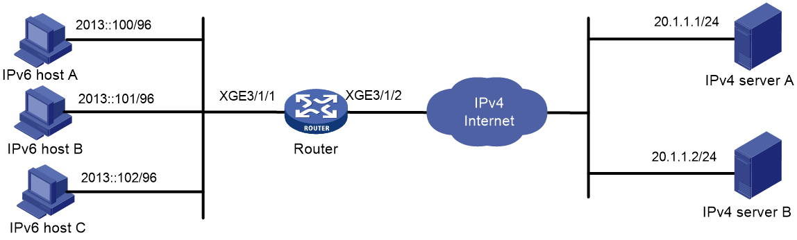
As shown in Figure 7, a company upgrades the network to IPv6 and has IPv4 addresses 10.1.1.1 to 10.1.1.3. Configure AFT policies to allow IPv6 hosts on subnet 2013::/96 to access the IPv4 Internet by using IPv4 addresses 10.1.1.1 to 10.1.1.3.
Requirements analysis
To meet the network configuration requirements, you must perform the following tasks:
· Configure a NAT64 prefix to translate IPv4 addresses of IPv4 servers to IPv6 addresses.
· Configure an IPv6-to-IPv4 source address dynamic translation policy to translate source IPv6 addresses of IPv6-initiated packets to IPv4 addresses in the range of 10.1.1.1 to 10.1.1.3.
Procedure
# Specify IP addresses for the interfaces on the router. (Details not shown.)
# Configure QoS to steer traffic that requires AFT processing to the AFT-capable service card. (Details not shown.)
# Create AFT address group 0, and add addresses 10.1.1.1 to 10.1.1.3 to the group.
<Router> system-view
[Router] aft address-group 0
[Router-aft-address-group-0] address 10.1.1.1 10.1.1.3
[Router-aft-address-group-0] quit
# Configure IPv6 ACL 2000 to permit IPv6 packets only from subnet 2013::/96 to pass through.
[Router] acl ipv6 basic 2000
[Router-acl-ipv6-basic-2000] rule permit source 2013:: 96
[Router-acl-ipv6-basic-2000] rule deny
[Router-acl-ipv6-basic-2000] quit
# Configure the router to translate source IPv6 addresses of packets permitted by IPv6 ACL 2000 to IPv4 addresses in address group 0.
[Router] aft v6tov4 source acl ipv6 number 2000 address-group 0
# Configure the router to use NAT64 prefix 2012::/96 to translate destination IPv6 addresses of IPv6 packets.
[Router] aft prefix-nat64 2012:: 96
# Enable AFT on Ten-GigabitEthernet 3/1/1, which is connected to the IPv6 network.
[Router] interface ten-gigabitethernet 3/1/1
[Router-Ten-GigabitEthernet3/1/1] aft enable
[Router-Ten-GigabitEthernet3/1/1] quit
# Enable AFT on Ten-GigabitEthernet 3/1/2, which is connected to the IPv4 Internet.
[Router] interface ten-gigabitethernet 3/1/2
[Router-Ten-GigabitEthernet3/1/2] aft enable
[Router-Ten-GigabitEthernet3/1/2] quit
Verifying the configuration
# Verify the connectivity between IPv6 hosts and IPv4 servers. This example pings IPv4 server A from IPv6 host A.
D:\>ping 2012::20.1.1.1
Pinging 2012::20.1.1.1 with 32 bytes of data:
Reply from 2012::20.1.1.1: time=3ms
Reply from 2012::20.1.1.1: time=3ms
Reply from 2012::20.1.1.1: time=3ms
Reply from 2012::20.1.1.1: time=3ms
# Display detailed information about IPv6 AFT sessions on the router.
[Router] display aft session ipv6 verbose
Initiator:
Source IP/port: 2013::100/0
Destination IP/port: 2012::1401:0101/32768
VPN instance/VLAN ID/Inline ID: -/-/-
Protocol: IPV6-ICMP(58)
Inbound interface: Ten-GigabitEthernet3/1/1
Responder:
Source IP/port: 2012::1401:0101/0
Destination IP/port: 2013::100/33024
VPN instance/VLAN ID/Inline ID: -/-/-
Protocol: IPV6-ICMP(58)
Inbound interface: Ten-GigabitEthernet3/1/2
State: ICMPV6_REPLY
Application: OTHER
Start time: 2014-03-13 08:52:59 TTL: 23s
Initiator->Responder: 4 packets 320 bytes
Responder->Initiator: 4 packets 320 bytes
Total sessions found: 1
# Display detailed information about IPv4 AFT sessions on the router.
[Router] display aft session ipv4 verbose
Initiator:
Source IP/port: 10.1.1.1/1025
Destination IP/port: 20.1.1.1/2048
DS-Lite tunnel peer: -
VPN instance/VLAN ID/Inline ID: -/-/-
Protocol: ICMP(1)
Inbound interface: Ten-GigabitEthernet3/1/1
Responder:
Source IP/port: 20.1.1.1/1025
Destination IP/port: 10.1.1.1/0
DS-Lite tunnel peer: -
VPN instance/VLAN ID/Inline ID: -/-/-
Protocol: ICMP(1)
Inbound interface: Ten-GigabitEthernet3/1/2
State: ICMP_REPLY
Application: OTHER
Start time: 2014-03-13 08:52:59 TTL: 27s
Initiator->Responder: 4 packets 240 bytes
Responder->Initiator: 4 packets 240 bytes
Total sessions found: 1
Example: Providing FTP service from an IPv6 network to the IPv4 Internet
Network configuration
As shown in Figure 8, a company upgrades the network to IPv6, and it has an IPv4 address 10.1.1.1.
To allow the IPv6 FTP server to provide FTP services to IPv4 hosts, configure the following AFT policies on the router:
· Map the IPv6 FTP server's IPv6 address and TCP port number to the company's IPv4 address and TCP port number.
· Configure a NAT64 prefix to translate source IPv4 addresses of IPv4 packets to source IPv6 addresses.

Procedure
# Specify IP addresses for the interfaces on the router. (Details not shown.)
# Map IPv4 address 10.1.1.1 with TCP port 21 to IPv6 address 2013::102 with TCP port 21 for the IPv6 internal FTP server.
<Router> system-view
[Router] aft v6server protocol tcp 10.1.1.1 21 2013::102 21
# Configure the router to use NAT64 prefix 2012:: 96 to translate source addresses of IPv4 packets.
[Router] aft prefix-nat64 2012:: 96
# Enable AFT on Ten-GigabitEthernet 3/1/1, which is connected to the IPv4 Internet.
[Router] interface ten-gigabitethernet 3/1/1
[Router-Ten-GigabitEthernet3/1/1] aft enable
[Router-Ten-GigabitEthernet3/1/1] quit
# Enable AFT on Ten-GigabitEthernet 3/1/2, which is connected to the IPv6 FTP server.
[Router] interface ten-gigabitethernet 3/1/2
[Router-Ten-GigabitEthernet3/1/2] aft enable
[Router-Ten-GigabitEthernet3/1/2] quit
Verifying the configuration
# Verify that IPv4 hosts can use FTP to access the IPv6 FTP server. (Details not shown.)
# Display detailed information about IPv6 AFT sessions on the router.
[Router] display aft session ipv4 verbose
Initiator:
Source IP/port: 20.1.1.1/11025
Destination IP/port: 10.1.1.1/21
DS-Lite tunnel peer: -
VPN instance/VLAN ID/Inline ID: -/-/-
Protocol: TCP(6)
Inbound interface: Ten-GigabitEthernet3/1/1
Responder:
Source IP/port: 10.1.1.1/21
Destination IP/port: 20.1.1.1/11025
DS-Lite tunnel peer: -
VPN instance/VLAN ID/Inline ID: -/-/-
Protocol: TCP(6)
Inbound interface: Ten-GigabitEthernet3/1/2
State: TCP_ESTABLISHED
Application: FTP
Start time: 2014-03-13 09:07:30 TTL: 3577s
Initiator->Responder: 3 packets 124 bytes
Responder->Initiator: 2 packets 108 bytes
Total sessions found: 1
# Display detailed information about IPv4 AFT sessions on the router.
[Router] display aft session ipv6 verbose
Initiator:
Source IP/port: 2012::1401:0101/1029
Destination IP/port: 2013::102/21
VPN instance/VLAN ID/Inline ID: -/-/-
Protocol: TCP(6)
Inbound interface: Ten-GigabitEthernet3/1/1
Responder:
Source IP/port: 2013::102/21
Destination IP/port: 2012::1401:0101/1029
VPN instance/VLAN ID/Inline ID: -/-/-
Protocol: TCP(6)
Inbound interface: Ten-GigabitEthernet3/1/2
State: TCP_ESTABLISHED
Application: FTP
Start time: 2014-03-13 09:07:30 TTL: 3582s
Initiator->Responder: 3 packets 184 bytes
Responder->Initiator: 2 packets 148 bytes
Total sessions found: 1
Example: Allowing mutual access between IPv4 and IPv6 networks
Network configuration
As shown in Figure 9, a company deploys both an IPv4 network and an IPv6 network.
To allow mutual access between the IPv4 network and the IPv6 network, configure the following AFT policies on the router:
· Assign an IVI prefix and an IPv4 subnet to the IPv6 network. Each IPv6 host uses the IPv6 addresses formed by the IVI prefix and an IPv4 address on the IPv4 subnet.
· Configure a NAT64 prefix to translate source IPv4 addresses of packets initiated by the IPv4 network to IPv6 addresses.

Procedure
# Specify IP addresses for the interfaces on the router. The IPv6 addresses for IPv6 hosts are calculated by the IVI prefix 2013::/32 and IPv4 addresses in the range of 20.1.1.0/24. (Details not shown.)
# Configure IPv4 ACL 2000 to permits all IPv4 packets to pass through.
<Router> system-view
[Router] acl basic 2000
[Router-acl-ipv4-basic-2000] rule permit
[Router-acl-ipv4-basic-2000] quit
# Configure the router to use NAT64 prefix 2012:: 96 to translate source addresses of IPv4 packets. The router also uses the prefix to translate destination addresses of IPv6 packets.
[Router] aft prefix-nat64 2012:: 96
# Configure the router to use IVI prefix 2013:: to translate source addresses of IPv6 packets.
[Router] aft prefix-ivi 2013::
# Configure the router to use IVI prefix 2013:: to translate destination addresses of packets permitted by IPv4 ACL 2000.
[Router] aft v4tov6 destination acl number 2000 prefix-ivi 2013::
# Enable AFT on Ten-GigabitEthernet3/1/1, which is connected to the IPv4 network.
[Router] interface ten-gigabitethernet 3/1/1
[Router-Ten-GigabitEthernet3/1/1] aft enable
[Router-Ten-GigabitEthernet3/1/1] quit
# Enable AFT on Ten-GigabitEthernet3/1/2, which is connected to the IPv6 network.
[Router] interface ten-gigabitethernet 3/1/2
[Router-Ten-GigabitEthernet3/1/2] aft enable
[Router-Ten-GigabitEthernet3/1/2] quit
Verifying the configuration
# Verify the connectivity between IPv6 hosts and IPv4 hosts. This example pings IPv4 host A from IPv6 host A.
D:\>ping 2012::a01:0101
Pinging 2012::a01:0101 with 32 bytes of data:
Reply from 2012::a01:0101: time=3ms
Reply from 2012::a01:0101: time=3ms
Reply from 2012::a01:0101: time=3ms
Reply from 2012::a01:0101: time=3ms
# Display information about IPv6 AFT sessions on the router.
[Router] display aft session ipv6 verbose
Initiator:
Source IP/port: 2013:0:FF14:0101:0100::/0
Destination IP/port: 2012::0a01:0101/32768
VPN instance/VLAN ID/Inline ID: -/-/-
Protocol: IPV6-ICMP(58)
Inbound interface: Ten-GigabitEthernet3/1/2
Responder:
Source IP/port: 2012::0a01:0101/0
Destination IP/port: 2013:0:FF14:0101:0100::/33024
VPN instance/VLAN ID/Inline ID: -/-/-
Protocol: IPV6-ICMP(58)
Inbound interface: Ten-GigabitEthernet3/1/1
State: ICMPV6_REPLY
Application: OTHER
Start time: 2014-03-13 08:52:59 TTL: 23s
Initiator->Responder: 4 packets 320 bytes
Responder->Initiator: 4 packets 320 bytes
Total sessions found: 1
# Display information about IPv4 AFT sessions on the router.
[Router] display aft session ipv4 verbose
Initiator:
Source IP/port: 20.1.1.1/1025
Destination IP/port: 10.1.1.1/2048
DS-Lite tunnel peer: -
VPN instance/VLAN ID/Inline ID: -/-/-
Protocol: ICMP(1)
Inbound interface: Ten-GigabitEthernet3/1/2
Responder:
Source IP/port: 10.1.1.1/1025
Destination IP/port: 20.1.1.1/0
DS-Lite tunnel peer: -
VPN instance/VLAN ID/Inline ID: -/-/-
Protocol: ICMP(1)
Inbound interface: Ten-GigabitEthernet3/1/1
State: ICMP_REPLY
Application: OTHER
Start time: 2014-03-13 08:52:59 TTL: 27s
Initiator->Responder: 4 packets 240 bytes
Responder->Initiator: 4 packets 240 bytes
Total sessions found: 1
Example: Allowing IPv6 Internet access from an IPv4 network
Network configuration
As shown in Figure 10, a company deploys an IPv4 network, and the Internet migrates to IPv6.
To allow IPv4 hosts to access the IPv6 server in the IPv6 Internet, configure the following AFT policies on the router:
· Configure an IPv4-to-IPv6 source address translation policy.
· Configure an IPv6-to-IPv4 source address static mapping for the IPv6 server.

Procedure
# Specify IP addresses for the interfaces on the router. (Details not shown.)
# Configure IPv4 ACL 2000 to permit IPv4 packets only from subnet 10.1.1.0/24 to pass through.
<Router> system-view
[Router] acl basic 2000
[Router-acl-ipv4-basic-2000] rule permit source 10.1.1.0 0.0.0.255
[Router-acl-ipv4-basic-2000] rule deny
[Router-acl-ipv4-basic-2000] quit
# Configure NAT64 prefix 2012:: 96.
[Router] aft prefix-nat64 2012:: 96
# Configure the router to use NAT64 prefix 2012:: 96 to translate source addresses of packets permitted by IPv4 ACL 2000.
[Router] aft v4tov6 source acl number 2000 prefix-nat64 2012:: 96
# Map source IPv6 address 2013:0:ff14:0101:100:: to source IPv4 address 20.1.1.1.
[Router] aft v6tov4 source 2013:0:ff14:0101:100::1 20.1.1.1
# Enable AFT on Ten-GigabitEthernet 3/1/1, which is connected to the IPv4 network.
[Router] interface ten-gigabitethernet 3/1/1
[Router-Ten-GigabitEthernet3/1/1] aft enable
[Router-Ten-GigabitEthernet3/1/1] quit
# Enable AFT on Ten-GigabitEthernet 3/1/2, which is connected to the IPv6 Internet.
[Router] interface ten-gigabitethernet 3/1/2
[Router-Ten-GigabitEthernet3/1/2] aft enable
[Router-Ten-GigabitEthernet3/1/2] quit
Verifying the configuration
# Verify the connectivity between the IPv4 hosts and the IPv6 server. This example uses the ping utility on an IPv4 host.
D:\>ping 20.1.1.1
Pinging 20.1.1.1 with 32 bytes of data:
Reply from 20.1.1.1: bytes=32 time=14ms TTL=63
Reply from 20.1.1.1: bytes=32 time=1ms TTL=63
Reply from 20.1.1.1: bytes=32 time=1ms TTL=63
Reply from 20.1.1.1: bytes=32 time=1ms TTL=63
# Display detailed information about IPv6 AFT sessions on the router.
[Router] display aft session ipv4 verbose
Initiator:
Source IP/port: 10.1.1.1/1025
Destination IP/port: 20.1.1.1/2048
DS-Lite tunnel peer: -
VPN instance/VLAN ID/Inline ID: -/-/-
Protocol: ICMP(1)
Inbound interface: Ten-GigabitEthernet3/1/1
Responder:
Source IP/port: 20.1.1.1/1025
Destination IP/port: 10.1.1.1/0
DS-Lite tunnel peer: -
VPN instance/VLAN ID/Inline ID: -/-/-
Protocol: ICMP(1)
Inbound interface: Ten-GigabitEthernet3/1/2
State: ICMP_REPLY
Application: OTHER
Start time: 2014-03-13 08:52:59 TTL: 27s
Initiator->Responder: 4 packets 240 bytes
Responder->Initiator: 4 packets 240 bytes
Total sessions found: 1
# Display detailed information about IPv4 AFT sessions on the router.
[Router] display aft session ipv6 verbose
Initiator:
Source IP/port: 2012::0A01:0101/0
Destination IP/port: 2013:0:FF14:0101:0100::/32768
VPN instance/VLAN ID/Inline ID: -/-/-
Protocol: IPV6-ICMP(58)
Inbound interface: Ten-GigabitEthernet3/1/1
Responder:
Source IP/port: 2013:0:FF14:0101:0100::/0
Destination IP/port: 2012::0A01:0101/33024
VPN instance/VLAN ID/Inline ID: -/-/-
Protocol: IPV6-ICMP(58)
Inbound interface: Ten-GigabitEthernet3/1/2
State: ICMPV6_REPLY
Application: OTHER
Start time: 2014-03-13 08:52:59 TTL: 23s
Initiator->Responder: 4 packets 320 bytes
Responder->Initiator: 4 packets 320 bytes
Total sessions found: 1
Example: Providing FTP service from an IPv4 network to the IPv6 Internet
Network configuration
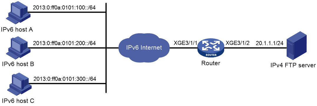
As shown in Figure 11, a company deploys an IPv4 network, and it has an IPv6 address 2012::1. The Internet migrates to IPv6.
To allow the IPv4 FTP server to provide FTP services to IPv6 hosts, configure the following AFT policies on the router:
· Configure an IPv4-to-IPv6 source address static mapping for the IPv4 FTP server. The router uses the mapping to translate the destination IPv6 address of IPv6-initiated addresses to the IPv4 address.
· Configure an IPv6-to-IPv4 source address dynamic translation policy. The router translates source IPv6 addresses of IPv6-initiated packets to source IPv4 addresses 30.1.1.1 and 30.1.1.2.
Procedure
# Specify IP addresses for the interfaces on the router. (Details not shown.)
# Map source IPv4 address 20.1.1.1 to source IPv6 address 2012::1.
<Router> system-view
[Router] aft v4tov6 source 20.1.1.1 2012::1
# Configure address group 0, and add addresses 30.1.1.1 to 30.1.1.2 to the group.
[Router] aft address-group 0
[Router-aft-address-group-0] address 30.1.1.1 30.1.1.2
[Router-aft-address-group-0] quit
# Configure IPv6 ACL 2000 to permit all IPv6 packets to pass through.
[Router] acl ipv6 basic 2000
[Router-acl-ipv6-basic-2000] rule permit
[Router-acl-ipv6-basic-2000] quit
# Configure the router to translate source addresses of IPv6 packets permitted by IPv6 ACL 2000 to IPv4 addresses in address group 0.
[Router] aft v6tov4 source acl ipv6 number 2000 address-group 0
# Enable AFT on Ten-GigabitEthernet 3/1/1, which is connected to the IPv6 Internet.
[Router] interface ten-gigabitethernet 3/1/1
[Router-Ten-GigabitEthernet3/1/1] aft enable
[Router-Ten-GigabitEthernet3/1/1] quit
# Enable AFT on Ten-GigabitEthernet 3/1/2, which is connected to the IPv4 network.
[Router] interface ten-gigabitethernet 3/1/2
[Router-Ten-GigabitEthernet3/1/2] aft enable
[Router-Ten-GigabitEthernet3/1/2] quit
Verifying the configuration
# Verify the connectivity between the IPv6 hosts and the IPv4 FTP server. For example, ping the IPv4 FTP server from IPv6 host A.
D:\>ping 2012::1
Pinging 2012::1 with 32 bytes of data:
Reply from 2012::1: time=3ms
Reply from 2012::1: time=3ms
Reply from 2012::1: time=3ms
Reply from 2012::1: time=3ms
# Display detailed information about IPv6 AFT sessions on the router.
[Router] display aft session ipv6 verbose
Initiator:
Source IP/port: 2013:0:FF0A:0101:0100::/1029
Destination IP/port: 2012::1/21
VPN instance/VLAN ID/Inline ID: -/-/-
Protocol: TCP(6)
Inbound interface: Ten-GigabitEthernet3/1/1
Responder:
Source IP/port: 2012::1/21
Destination IP/port: 2013:0:FF0A:0101:0100::/1029
VPN instance/VLAN ID/Inline ID: -/-/-
Protocol: TCP(6)
Inbound interface: Ten-GigabitEthernet3/1/2
State: TCP_ESTABLISHED
Application: FTP
Start time: 2014-03-13 09:07:30 TTL: 3582s
Initiator->Responder: 3 packets 184 bytes
Responder->Initiator: 2 packets 148 bytes
Total sessions found: 1
# Display detailed information about IPv4 AFT sessions on the router.
[Router] display aft session ipv4 verbose
Initiator:
Source IP/port: 30.1.1.1/11025
Destination IP/port: 20.1.1.1/21
DS-Lite tunnel peer: -
VPN instance/VLAN ID/Inline ID: -/-/-
Protocol: TCP(6)
Inbound interface: Ten-GigabitEthernet3/1/1
Responder:
Source IP/port: 20.1.1.1/21
Destination IP/port: 30.1.1.1/11025
DS-Lite tunnel peer: -
VPN instance/VLAN ID/Inline ID: -/-/-
Protocol: TCP(6)
Inbound interface: Ten-GigabitEthernet3/1/2
State: TCP_ESTABLISHED
Application: FTP
Start time: 2014-03-13 09:07:30 TTL: 3577s
Initiator->Responder: 3 packets 124 bytes
Responder->Initiator: 2 packets 108 bytes
Total sessions found: 1
AFT configuration examples (in CGN scenarios)
Example: Allowing IPv4 Internet access from an IPv6 network
Network configuration
As shown in Figure 12, a company upgrades the network to IPv6 and has IPv4 addresses 10.1.1.1 to 10.1.1.3. Configure AFT policies to allow IPv6 hosts on subnet 2013::/96 to access the IPv4 Internet by using IPv4 addresses 10.1.1.1 to 10.1.1.3.

Requirements analysis
To meet the network configuration requirements, you must perform the following tasks:
· Configure a NAT64 prefix to translate IPv4 addresses of IPv4 servers to IPv6 addresses.
· Configure an IPv6-to-IPv4 source address dynamic translation policy to translate source IPv6 addresses of IPv6-initiated packets to IPv4 addresses in the range of 10.1.1.1 to 10.1.1.3.
Procedure
# Specify IP addresses for the interfaces on the router. (Details not shown.)
# Create a failover group named cgn.
<Router> system-view
[Router] failover group cgn
# Specify a slot that supports CGN as the primary node in failover group cgn. (The slot number is used only as an example.)
[Router-failover-group-cgn] bind slot 5 primary
[Router-failover-group-cgn] quit
# Create AFT address group 0, and add addresses 10.1.1.1 to 10.1.1.3 to the group.
[Router] aft address-group 0
[Router-aft-address-group-0] address 10.1.1.1 10.1.1.3
[Router-aft-address-group-0] failover-group cgn
# Configure IPv6 ACL 2000 to permit IPv6 packets only from subnet 2013::/96 to pass through.
[Router] acl ipv6 basic 2000
[Router-acl-ipv6-basic-2000] rule permit source 2013:: 96
[Router-acl-ipv6-basic-2000] rule deny
[Router-acl-ipv6-basic-2000] quit
# Configure traffic class cgn and traffic behavior cgn to redirect IPv6 packets matching ACL 2000 to failover group cgn.
[Router] traffic classifier cgn
[Router-classifier-cgn] if-match acl ipv6 2000
[Router-classifier-cgn] quit
[Router] traffic behavior cgn
[Router-behavior-cgn] redirect failover-group cgn
[Router-behavior-cgn] quit
# Configure a QoS policy and associate the traffic class with the traffic behavior.
[Router] qos policy cgn
[Router-qospolicy-cgn] classifier cgn behavior cgn
[Router-qospolicy-cgn] quit
# Apply the QoS policy to the inbound traffic on Ten-GigabitEthernet 3/1/1.
[Router] interface ten-gigabitethernet 3/1/1
[Router-Ten-GigabitEthernet3/1/1] qos apply policy cgn inbound
[Router-Ten-GigabitEthernet3/1/1] quit
# Configure the router to translate source IPv6 addresses of packets permitted by IPv6 ACL 2000 to IPv4 addresses in address group 0, and set the port block size to 200.
[Router] aft v6tov4 source acl ipv6 number 2000 address-group 0 port-block-size 200
# Configure the router to use NAT64 prefix 2012::/96 to translate destination IPv6 addresses of IPv6 packets.
[Router] aft prefix-nat64 2012:: 96
# Enable AFT on Ten-GigabitEthernet 3/1/1, which is connected to the IPv6 network.
[Router] interface ten-gigabitethernet 3/1/1
[Router-Ten-GigabitEthernet3/1/1] aft enable
[Router-Ten-GigabitEthernet3/1/1] quit
# Enable AFT on Ten-GigabitEthernet 3/1/2, which is connected to the IPv4 Internet.
[Router] interface ten-gigabitethernet 3/1/2
[Router-Ten-GigabitEthernet3/1/2] aft enable
[Router-Ten-GigabitEthernet3/1/2] quit
# Configure the failover group to process session-based services. Traffic permitted by ACL 2000 is redirected to the primary node of failover group cgn for service processing.
[Router] session service-location acl ipv6 2000 failover-group cgn
# Enable flow-triggered port block assignment.
[Router] aft port-block flow-trigger enable
Verifying the configuration
# Verify the connectivity between IPv6 hosts and IPv4 servers. This example pings IPv4 server A from IPv6 host A.
D:\>ping 2012::1
Pinging 2012::1 with 32 bytes of data:
Reply from 2012::1: time=3ms
Reply from 2012::1: time=3ms
Reply from 2012::1: time=3ms
Reply from 2012::1: time=3ms
# Display detailed information about IPv6 AFT sessions on the router.
[Router] display aft session ipv6 verbose
Initiator:
Source IP/port: 2013::100/1024
Destination IP/port: 2012::1401:101/1025
VPN instance/VLAN ID/Inline ID: -/-/-
Protocol: UDP(17)
Inbound interface: Ten-GigabitEthernet3/1/1
Responder:
Source IP/port: 2012::1401:101/1025
Destination IP/port: 2013::100/1024
VPN instance/VLAN ID/Inline ID: -/-/-
Protocol: UDP(17)
Inbound interface: Ten-GigabitEthernet3/1/2
State: UDP_OPEN
Application: OTHER
Role: -
Failover group ID: -
Start time: 2019-01-08 07:59:11 TTL: 99555s
Initiator->Responder: 0 packets 0 bytes
Responder->Initiator: 0 packets 0 bytes
Total sessions found: 1
# Display detailed information about IPv4 AFT sessions on the router.
[Router] display aft session ipv4 verbose
Initiator:
Source IP/port: 10.1.1.2/1024
Destination IP/port: 20.1.1.1/1025
DS-Lite tunnel peer: -
VPN instance/VLAN ID/Inline ID: -/-/-
Protocol: UDP(17)
Inbound interface: Ten-GigabitEthernet3/1/1
Responder:
Source IP/port: 20.1.1.1/1025
Destination IP/port: 10.1.1.2/1024
DS-Lite tunnel peer: -
VPN instance/VLAN ID/Inline ID: -/-/-
Protocol: UDP(17)
Inbound interface: Ten-GigabitEthernet3/1/2
State: UDP_OPEN
Application: OTHER
Role: -
Failover group ID: -
Start time: 2019-01-08 07:59:11 TTL: 99443s
Initiator->Responder: 0 packets 0 bytes
Responder->Initiator: 0 packets 0 bytes
Total sessions found: 1
# Display AFT port block mappings.
[Router] display aft port-block
IPv6 Address: 2013::100
IPv4 Address: 10.1.1.2
Port block : [1024 - 1223]
Total entries found: 1
Example: Allowing IPv4 Internet access from an IPv6 network in a CP-UP separation scenario
Network configuration
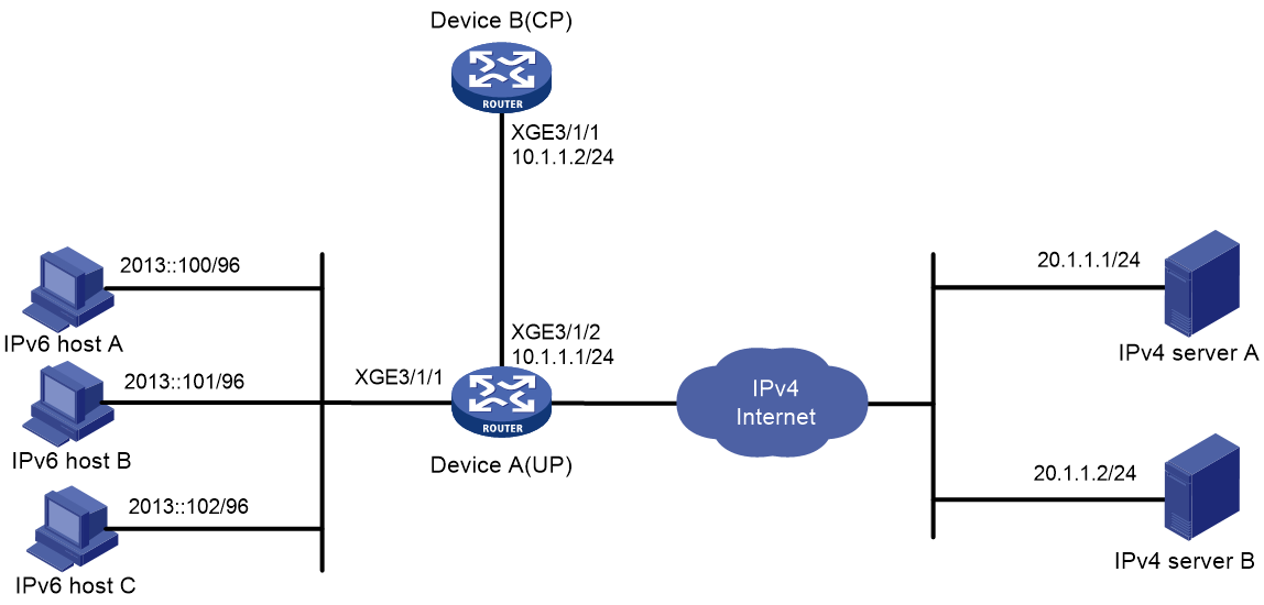
As shown in Figure 13, a company upgrades its network to an IPv6 network. Configure the CP-UP separation solution so that only hosts in the internal subnet 2013::/96 can access IPv4 Internet through PPPoE clients.
The CP device (Device B) processes services including user identification, authentication, authorization, accounting, address allocation, and access control. The UP device (Device A) processes services including address translation, port block allocation, packet forwarding, and traffic control.
Device A also works as a DHCP server to provide public IPv4 addresses in subnet 1.1.0.0/16 for internal IPv6 users.
Prerequisites
Assign IP addresses to interfaces and make sure routes between devices are reachable. (Details not shown.)
Configuring the CP device
Commands for configuring a device acting as a CP vary by version. This section is only for your reference. For details about CP configuration, see the product documents for the device.
1. Create a remote interface:
# Create UP 1024 and enter UP-manage view.
<DeviceB> system-view
[DeviceB] up-manage id 1024
# Create Remote-XGE1024/3/1/1.
[DeviceB-manage-1024] remote interface ten-gigabitethernet 3/1/1
[DeviceB-manage-1024] quit
2. Configure an IP pool:
# Create a NAT-central IP pool.
[DeviceB] ip pool dhcp nat-central
# Specify network 1.1.0.0/16 for dynamic allocation in the IP pool.
[DeviceB-ip-pool-dhcp] network 1.1.0.0 mask 255.255.0.0
# Set the mask length to 24 for dynamically allocated subnets in the IP pool.
[DeviceB-ip-pool-dhcp] subnet mask-length 24
[DeviceB-ip-pool-dhcp] quit
3. Configure the PPPoE server:
# Create a local PPPoE user.
[DeviceB] local-user user1 class network
[DeviceB-luser-network-user1] password simple 123456789
[DeviceB-luser-network-user1] service-type ppp
[DeviceB-luser-network-user1] quit
# Configure Virtual-Template 1 to authenticate the peer by using PAP.
[DeviceB] interface virtual-template1
[DeviceB-Virtual-Template1] ppp authentication-mode pap domain cgn
[DeviceB-Virtual-Template1] quit
# Enable the PPPoE server on Remote-XGE1024/3/1/1, and bind the interface to Virtual-Template 1.
[DeviceB] interface remote-xge 1024/3/1/1
[DeviceB-Remote-XGE1024/3/1/1] pppoe-server bind virtual-template 1
[DeviceB-Remote-XGE1024/3/1/1] quit
4. Configure an ISP domain:
# Create an ISP domain named cgn.
[DeviceB] domain name cgn
# Specify local authentication, authorization, and accounting for PPP users.
[DeviceB-isp-cgn] authentication ppp local
[DeviceB-isp-cgn] authorization ppp local
[DeviceB-isp-cgn] accounting ppp local
# Specify the authorized IPv6 prefix 2013::/64.
[DeviceB-isp-cgn] authorization-attribute ipv6-prefix 2013:: 64
# Specify the user address type as NAT64. Success authentication of such users can trigger AFT.
[DeviceB-isp-cgn] user-address-type nat64
[DeviceB-isp-cgn] quit
Configuring the UP device
1. Configure Device A to operate in AFT user mode.
<DeviceA> system-view
[DeviceA] work-mode user-plane
2. Create a failover group:
# Create a failover group named cgn.
[DeviceA] failover group cgn
# Specify the primary node in the failover group. In this example, CGN-capable nodes are contained in the failover group.
[DeviceA-failover-group-cgn] bind slot 5 primary
[DeviceA-failover-group-cgn] quit
3. Configure an AFT address group:
# Create AFT address group 0.
[DeviceA] aft address-group 0
# Bind AFT address group 0 to DHCP IP pool dhcp.
[DeviceA-aft-address-group-0] bind dhcp-server-pool dhcp
[DeviceA-aft-address-group-0] failover-group cgn
[DeviceA-aft-address-group-0] quit
4. Create IPv6 basic ACL 2000 to identify packets from subnet 2013::/96.
[DeviceA] acl ipv6 basic 2000
[DeviceA-acl-ipv6-basic-2000] rule permit source 2013:: 96
[DeviceA-acl-ipv6-basic-2000] rule deny
[DeviceA-acl-ipv6-basic-2000] quit
5. Configure a QoS policy:
# Configure traffic class c1 and specify IPv6 ACL 2000 as the packet match criterion.
[DeviceA] traffic classifier cgn
[DeviceA-classifier-c1] if-match acl ipv6 2000
[DeviceA-classifier-c1] quit
# Configure traffic behavior b1 to redirect packets matching IPv6 ACL 2000 to failover group cgn.
[DeviceA] traffic behavior b1
[DeviceA-behavior-b1] redirect failover-group cgn
[DeviceA-behavior-b1] quit
# Create QoS policy cgn and associate the traffic class with the traffic behavior.
[DeviceA] qos policy cgn
[DeviceA-qospolicy-cgn] classifier c1 behavior b1
[DeviceA-qospolicy-cgn] quit
# Apply the QoS policy to the inbound traffic on Ten-GigabitEthernet 3/1/1.
[DeviceA] interface ten-gigabitethernet 3/1/1
[DeviceA-Ten-GigabitEthernet3/1/1] qos apply policy cgn inbound
[DeviceA-Ten-GigabitEthernet3/1/1] quit
6. Configure AFT:
# Configure the device to translate source IPv6 addresses of packets permitted by IPv6 ACL 2000 to IPv4 addresses in address group 0, and set the port block size to 200.
[DeviceA] aft v6tov4 source acl ipv6 number 2000 address-group 0 port-block-size 200
# Configure the device to use NAT64 prefix 2012::/96 to translate destination IPv6 addresses of the matching packets.
[DeviceA] aft prefix-nat64 2012:: 96
# Enable AFT on Ten-GigabitEthernet 3/1/1, which is connected to the IPv6 Internet.
[DeviceA] interface ten-gigabitethernet 3/1/1
[DeviceA-Ten-GigabitEthernet3/1/1] aft enable
[DeviceA-Ten-GigabitEthernet3/1/1] quit
# Enable AFT on Ten-GigabitEthernet 3/1/1, which is connected to the IPv4 Internet.
[DeviceA] interface ten-gigabitethernet 3/1/2
[DeviceA-Ten-GigabitEthernet3/1/2] aft enable
[DeviceA-Ten-GigabitEthernet3/1/2] quit
# Configure the failover group to process session-based services. Traffic permitted by IPv6 ACL 2000 is redirected to the primary node of failover group cgn for service processing.
[DeviceA] session service-location acl ipv6 2000 failover-group cgn
Verifying the configuration
# Verify the connectivity between the IPv6 hosts and the IPv4 server A. In this example, perform a ping operation on IPv6 host A.
D:\>ping 2012::1401:101
Pinging 2012::1401:101 with 32 bytes of data:
Reply from 2012::1401:101: time=3ms
Reply from 2012::1401:101: time=3ms
Reply from 2012::1401:101: time=3ms
Reply from 2012::1401:101: time=3ms
# Display detailed information about IPv6 AFT sessions on Device A.
[DeviceA] display aft session ipv6 verbose
Initiator:
Source IP/port: 2013::100/1024
Destination IP/port: 2012::1401:101/1025
VPN instance/VLAN ID/Inline ID: -/-/-
Protocol: UDP(17)
Inbound interface: Ten-GigabitEthernet3/1/1
Responder:
Source IP/port: 2012::1401:101/1025
Destination IP/port: 2013::100/1024
VPN instance/VLAN ID/Inline ID: -/-/-
Protocol: UDP(17)
Inbound interface: Ten-GigabitEthernet3/1/2
State: UDP_OPEN
Application: OTHER
Role: -
Failover group ID: -
Start time: 2019-01-08 07:59:11 TTL: 99555s
Initiator->Responder: 0 packets 0 bytes
Responder->Initiator: 0 packets 0 bytes
Total sessions found: 1
# Display detailed information about IPv4 AFT sessions on Device A.
[DeviceA] display aft session ipv4 verbose
Initiator:
Source IP/port: 1.1.0.2/1024
Destination IP/port: 20.1.1.1/1025
DS-Lite tunnel peer: -
VPN instance/VLAN ID/Inline ID: -/-/-
Protocol: UDP(17)
Inbound interface: Ten-GigabitEthernet3/1/1
Responder:
Source IP/port: 20.1.1.1/1025
Destination IP/port: 1.1.0.2/1024
DS-Lite tunnel peer: -
VPN instance/VLAN ID/Inline ID: -/-/-
Protocol: UDP(17)
Inbound interface: Ten-GigabitEthernet3/1/2
State: UDP_OPEN
Application: OTHER
Role: -
Failover group ID: -
Start time: 2019-01-08 07:59:11 TTL: 99443s
Initiator->Responder: 0 packets 0 bytes
Responder->Initiator: 0 packets 0 bytes
Total sessions found: 1
# Verify the AFT port block assignment.
[DeviceA] display aft port-block
IPv6 Address: 2013::100
IPv4 Address: 1.1.0.2
Port block : [1024 - 1223]
Total entries found: 1
