- Table of Contents
- Related Documents
-
| Title | Size | Download |
|---|---|---|
| 03-LEDs | 1.48 MB |
LEDs
Table 1 lists the LEDs available for the switch.
Table 1 LEDs at a glance
|
LEDs |
|
MPU LEDs
The LSXM2SUPT2, LSXM1SUPS2, and LSXM3SUPS2 MPUs provide similar LEDs as shown in Figure 1.
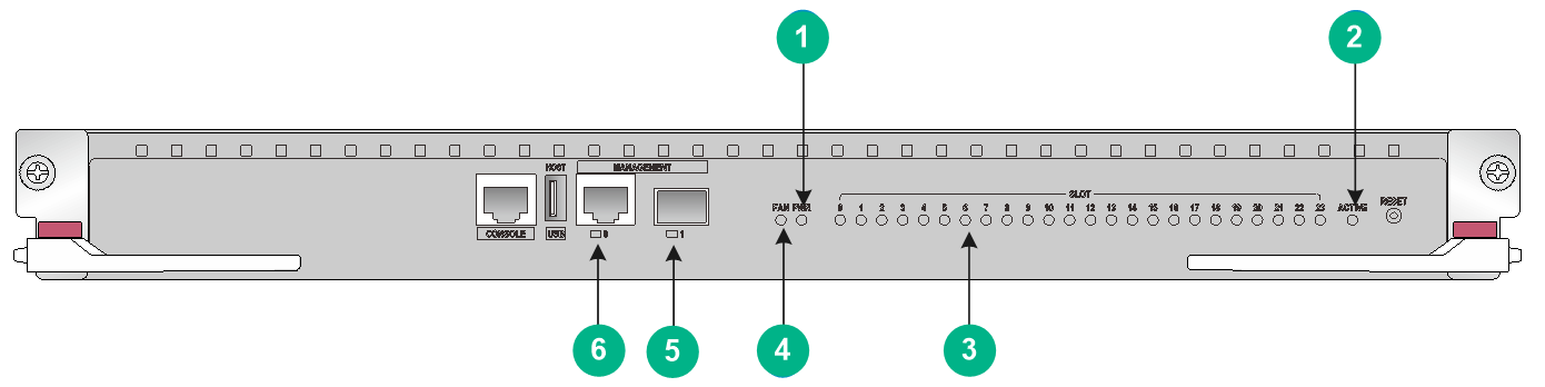
|
(1) Power module status LED (PWR) |
(2) MPU active/standby status LED (ACTIVE) |
|
(3) Module status LED (SLOT) |
(4) Fan tray status LED (FAN) |
|
(5) SFP management Ethernet port LED |
(6) 10/100/1000BASE-T management Ethernet port LED |
The LSXM1SUP04T2 MPU provides LEDs as shown in Figure 2.
Figure 2 LSXM1SUP04T2 MPU LEDs
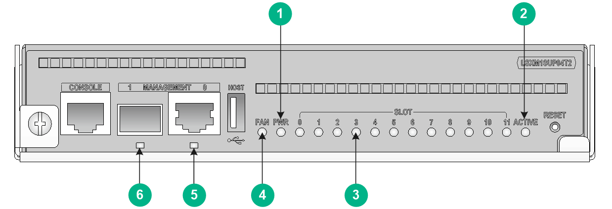
|
(1) Power module status LED (PWR) |
(2) MPU active/standby status LED (ACTIVE) |
|
(3) Module status LED (SLOT) |
(4) Fan tray status LED (FAN) |
|
(5) 10/100/1000BASE-T management Ethernet port LED |
(6) SFP management Ethernet port LED |
Management Ethernet port LEDs
10/100/1000BASE-T management Ethernet port LEDs
The MPU provides a LED for the 10/100/1000BASE-T management Ethernet port to indicate the link status and data forwarding status of the port.
Table 2 10/100/1000BASE-T management Ethernet port LED description
|
Status |
Description |
|
Flashing |
The management Ethernet port is receiving or sending data. |
|
On |
A link is present. |
|
Off |
No link is present. |
SFP management Ethernet port LEDs
The MPU provides a LED for the SFP management Ethernet port to indicate the link status and data forwarding status of the port.
Table 3 SFP management Ethernet port LED description
|
Status |
Description |
|
Flashing |
The SFP port is receiving or sending data. |
|
On |
A link is present. |
|
Off |
No link is present. |
|
|
NOTE: When a link is present on an SFP management Ethernet port, the LED is green and the port is operating at 1 Gbps. |
Fan tray status LEDs
The MPU provides a fan tray status LED to indicate the status of the fan trays.
Table 4 Fan tray status LED description
|
Status |
Description |
|
Steady green |
All fan trays are operating correctly. |
|
Steady red |
A fan tray has failed or no fan tray is present. |
|
Off |
The switch is not powered on. |
Power module status LEDs
The MPU provides a power module status LED to indicate the status of the power modules.
Table 5 Power module status LED description
|
Status |
Description |
|
Steady green |
All power modules are operating correctly. |
|
Steady red |
A minimum of one power module is faulty. |
|
Off |
The switch is not powered on. |
Module status LEDs
The MPU provides a status LED for a module to indicate the status of the module.
|
|
NOTE: The MPU and interface module slot numbers are marked at the left and right sides of the slots. The fabric module slot number is marked above the slot. |
Table 6 Module LED description
|
Status |
Description |
|
Flashing green (0.5 Hz) |
The module is operating correctly. |
|
Flashing green (4 Hz) |
The module is loading software. If the LED keeps in this state, the software versions of the switch and the module do not match. |
|
Steady green |
The module is starting up. |
|
Steady red |
A high severity alarm has occurred on the module or the module is faulty. |
|
Flashing red (0.25 Hz) |
The module temperature exceeds the upper warning threshold or falls below the lower warning threshold. |
|
Off |
The module is not present or the module is faulty. |
MPU active/standby status LED
The MPU has one ACTIVE LED to indicate the active or standby status of the MPU.
Table 7 MPU ACTIVE LED description
|
LED status |
Description |
|
On |
The MPU is active. |
|
Off |
· The MPU is in standby status. · The MPU is faulty. Examine the module status LED for the MPU to further determine the MPU status. |
Interface module LEDs
The interface modules provide RJ-45 ports, SFP ports, SFP+ ports, SFP28 ports, QSFP+ ports, and QSFP28 ports.
RJ-45 port LEDs
The interface modules provide one LED for each RJ-45 port to indicate the link status and data receiving/transmitting status of the RJ-45 ports.
Table 8 RJ-45 port LED description
|
LED status |
Description |
|
Flashing |
The RJ-45 port is receiving or sending data. |
|
On |
A link is present. |
|
Off |
No link is present. |
|
|
NOTE: An RJ-45 port LED uses color to indicate the data rate of the port. · The data rate of a 10/100/1000 Mbps RJ-45 port is 1000 Mbps when its LED is green and 10/100 Mbps when its LED is yellow. · The data rate of a 10GBASE-T RJ-45 port is 10 Gbps when its LED is green and 1 Gbps when its LED is yellow. |
SFP port LEDs
The interface modules provide one LED for each SFP port to indicate the link status and data receiving/transmitting status of the SFP ports.
Table 9 SFP port LED description
|
LED status |
Description |
|
Flashing |
The SFP port is receiving or sending data. |
|
On |
A link is present. |
|
Off |
No link is present. |
|
|
NOTE: An SFP port operates at 1 Gbps. Its LED is green when the link is connected. |
SFP+ port LEDs
The interface modules provide one LED for each SFP+ port to indicate the link status and data receiving/transmitting status of the SFP+ ports.
Table 10 SFP+ port LED description
|
LED status |
Description |
|
Flashing |
The SFP+ port is receiving or sending data. |
|
On |
A link is present. |
|
Off |
No link is present. |
SFP28 port LEDs
The interface modules provide one LED for each SFP28 port to indicate the link status and data receiving/transmitting status of the SFP28 ports.
Table 11 SFP28 port LED description
|
LED status |
Description |
|
Flashing |
The SFP28 port is receiving or sending data. |
|
On |
A link is present. |
|
Off |
No link is present. |
QSFP+ port LEDs
The interface modules provide one LED for each QSFP+ port to indicate the link status and data receiving/transmitting status of the QSFP+ ports.
Table 12 QSFP+ port LED description
|
QSFP+ port |
LED status |
Description |
|
Not split |
Flashing |
The QSFP+ port is receiving or sending data. |
|
On |
A link is present. |
|
|
Off |
No link is present. |
|
|
Split into four 10G channels |
Flashing |
A minimum of one channel is receiving or sending data. |
|
On |
A link is present on a minimum of one channel. |
|
|
Off |
No link is present. |
QSFP28 port LEDs
The interface modules provide one LED for each QSFP28 port to indicate the link status and data receiving/transmitting status of the QSFP28 ports.
Table 13 QSFP28 port LED description
|
LED status |
Description |
|
Flashing |
The QSFP28 port is receiving or sending data. |
|
On |
A link is present. |
|
Off |
No link is present. |
QSFP-DD port LEDs
The interface modules provide one LED for each QSFP-DD port to indicate the link status and data receiving/transmitting status of the QSFP-DD ports.
Table 14 QSFP-DD port LED description
|
LED status |
Description |
|
Flashing |
The QSFP-DD port is receiving or sending data. |
|
On |
A link is present. |
|
Off |
No link is present. |
Fabric module status LEDs
Fabric module status LED on a fabric module
A fabric module has a RUN/ALM LED to indicate its operating status.
Table 15 Description for the RUN/ALM LED on a fabric module
|
LED status |
Description |
|
Green |
The fabric module is operating correctly. |
|
Red |
The fabric module has failed or is loading software. |
|
Off |
No power is provided to the fabric module or the fabric module has not started loading software. |
Fabric module status LEDs on a fan tray
A fan tray provides a RUN and ALM LED pair for each fabric module it covers.
· On the S12516G-AF and S12508G-AF fan trays, the fabric module LED pairs correspond to the fabric modules the fan tray covers from left to right.
· On the S12504G-AF fan tray, the extend lines of the fabric module LED pairs correspond to the fabric module the fan tray covers from left to right.
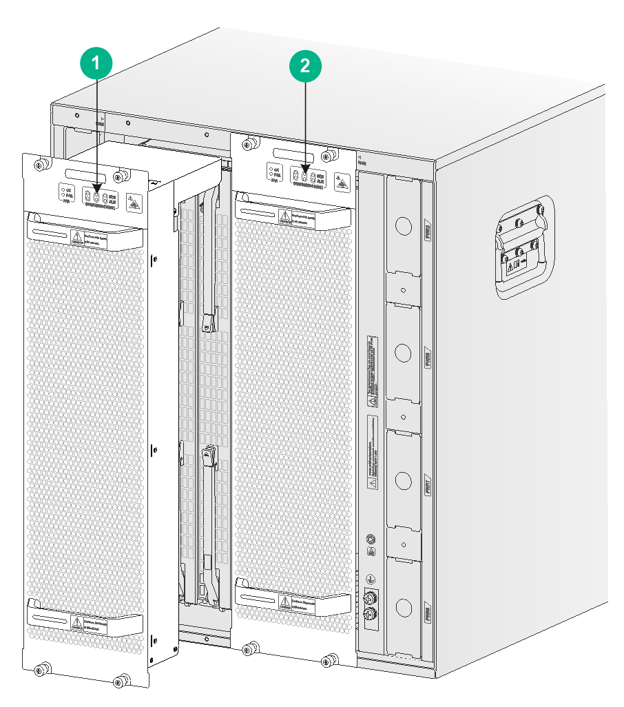
|
(1) LEDs for the fabric module slots 10 to 12 |
|
(2) LEDs for the fabric module slots 13 to 15 |
Figure 4 Corresponding relations between the LEDs on the S12504G-AF fan trays and fabric module slots
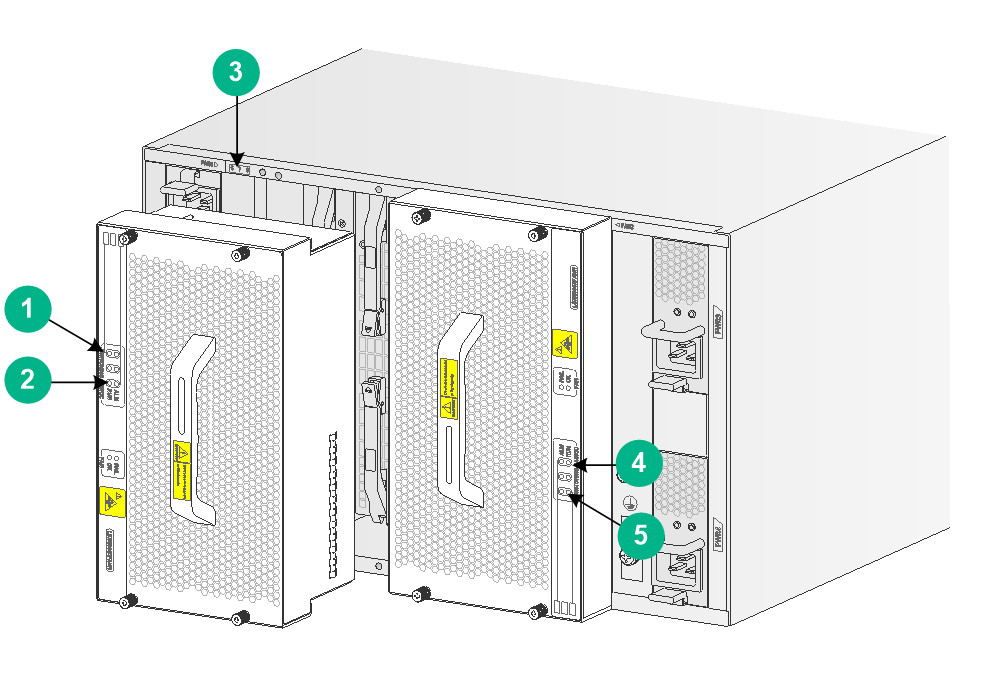
|
(1) LEDs for the fabric module slot 6 |
(2) LEDs for the fabric module slot 8 |
|
(3) Fabric module slot number |
(4) LEDs for the fabric module slot 9 |
|
(5) LEDs for the fabric module slot 11 |
|
Table 16 Description for fabric module status LEDs on a fan tray
|
RUN |
ALM |
Description |
|
Flashing (1 Hz) |
Off |
The fabric module is operating correctly. |
|
Off |
On |
The fabric module has failed. |
|
Flashing (1 Hz) |
On |
· The fabric module is loading software. · The fabric module is operating incorrectly. For example, the temperature exceeds the acceptable range. |
|
Off |
Off |
The fabric module has not started or is not powered on. |
|
On |
On |
The fabric module is booting. |
Fan tray LEDs
A fan tray uses an OK LED and a FAIL LED to indicate its operating status.
Table 17 Fan tray LED description
|
OK |
FAIL |
Description |
|
On |
Off |
The fan tray is operating correctly. |
|
Off |
On |
The fan tray is faulty. |
|
Off |
Off |
The fan tray is not powered on. |
Power module LEDs
Each power module provides two LEDs to indicate its operating status.
Table 18 Power module LED description
|
LED |
Status |
Description |
|
PSR2400-54A/PSR3000-54A |
||
|
AC |
Off |
· The power module has no power input. · The power module is in self-protection state because of low input voltage. |
|
Green |
The power input is normal. |
|
|
DC |
Green |
The power input is normal. |
|
Red |
The power module is in self-protection state because of one of the following issues: · Output short-circuit. · Output overcurrent. · Output overvoltage. · Input undervoltage. · Remote poweroff. |
|
|
Amber |
An overtemperature alarm has occurred on the power module. |
|
|
PSR2400-54D |
||
|
INPUT OK |
Off |
· The power module has no power input. · The power module is in self-protection state because of low input voltage. |
|
Green |
The power input is normal. |
|
|
OUTPUT OK |
Green |
The power input is normal. |
|
Red |
The power module is in self-protection state because of one of the following issues: · Output short-circuit. · Output overcurrent. · Output overvoltage. · Input undervoltage. · Remote poweroff. |
|
|
Amber |
An overtemperature alarm has occurred on the power module. |
|
|
PSR3000-54AHD |
||
|
IN |
Off |
· The power module has no power input. · The power module is in self-protection state because of low input voltage. |
|
Green |
The power input is normal. |
|
|
OUT |
Green |
The power input is normal. |
|
Amber |
An overtemperature alarm has occurred on the power module. |
|
|
Red |
The power module is in self-protection state because of one of the following problems: · Output overcurrent. · Output overvoltage. · Input undervoltage. · Overtemperature. · Remote poweroff. |
|
