- Table of Contents
- Related Documents
-
| Title | Size | Download |
|---|---|---|
| 01-Chassis Views and Technical Specifications | 4.80 MB |
Contents
1 Chassis views and technical specifications
Module power consumption and system power consumption
1 Chassis views and technical specifications
The H3C S12500G-AF Switch Series is a set of core switching products designed for the cloud computing data centers. It uses the advanced multi-stage multi-plane CLOS architecture to deliver the industry's highest switching performance, port density, availability, and most abundant cloud computing features.
The H3C S12500G-AF Switch Series includes the following models:
· S12504G-AF
· S12508G-AF
· S12516G-AF
Unless otherwise stated, MPUs, service modules, and fabric modules are collectively referred to as "modules" in this document.
Chassis views
The switch has an MPU section, service module section, power module section, fan tray section, and fabric module section.
|
|
NOTE: The chassis views in this section are for illustration only. |
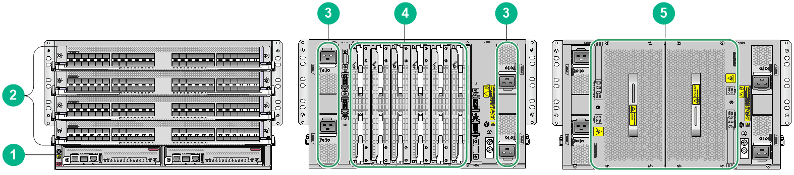
Figure1-1 Front and rear views of the S12504G-AF switch
|
(1) MPU section |
(2) Service module section |
(3) Power module section |
|
(4) Fabric module section |
(5) Fan tray section |
|
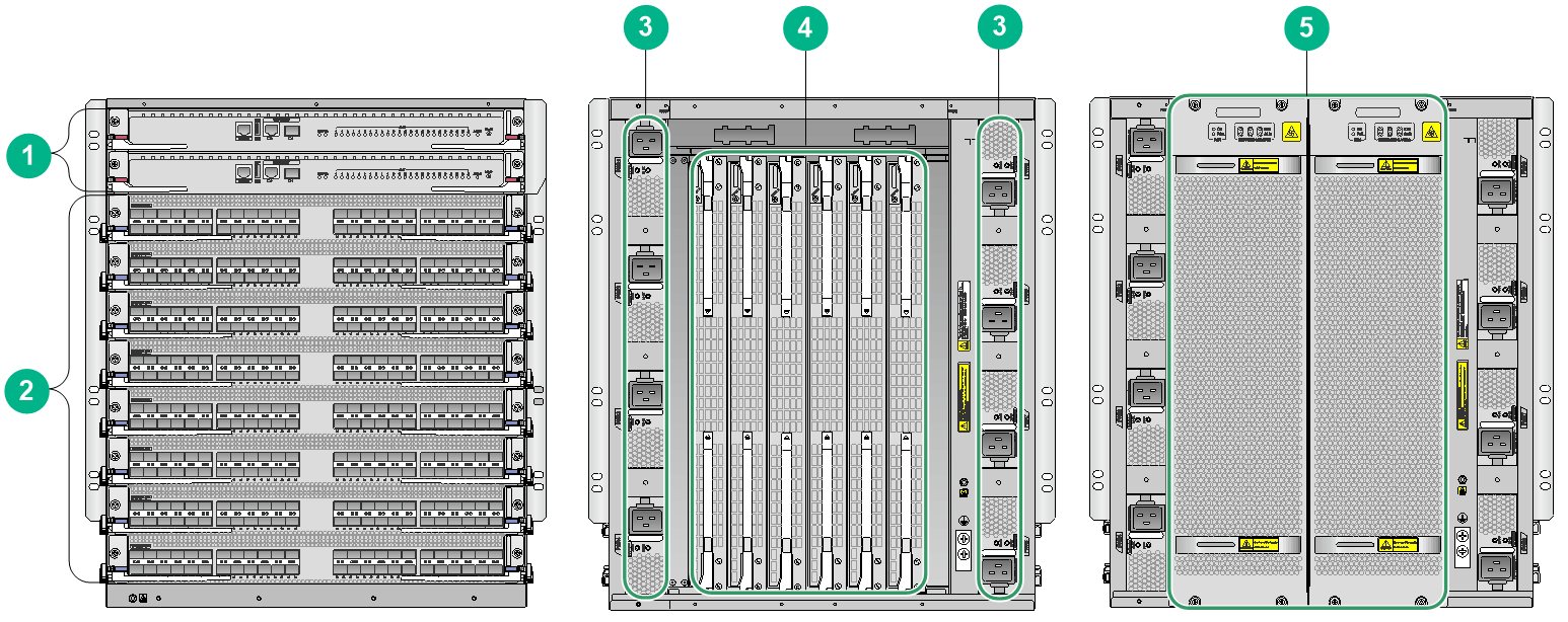
Figure1-2 Front and rear views of the S12508G-AF switch
|
(1) MPU section |
(2) Service module section |
(3) Power module section |
|
(4) Fabric module section |
(5) Fan tray section |
|
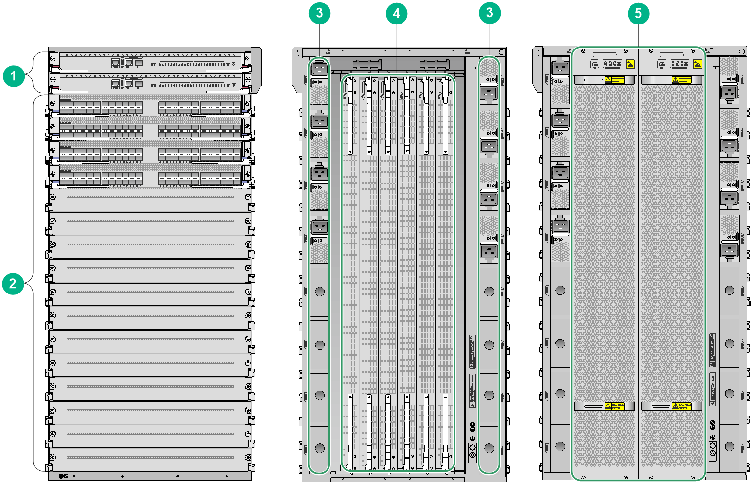
Figure1-3 Front and rear views of the S12516G-AF switch
|
(1) MPU section |
(2) Service module section |
(3) Power module section |
|
(4) Fabric module section |
(5) Fan tray section |
|
Table1-1 Description for the switch sections
|
Section |
Location identification |
Installation description |
|
MPU section |
Pink color is used for you to identify the MPU installation location. · S12516G-AF and S12508G-AF—The ejector lever pillow blocks on the MPU slots are pink marked. The MPU ejector levers are also pink marked to suggest the corresponding installation location. · S12504G-AF—The MPU slot numbers on the chassis are pink marked. The module identifiers on the MPUs are also pink marked to suggest the corresponding installation location. NOTE: The MPU section of an S12504G-AF is located below the service module section. |
No MPUs are provided with the switch. Purchase MPUs yourself. The switch has two MPU slots. You can install one MPU, or two MPUs for redundancy. To install only one MPU for the switch, you can install it in either of the MPU slots. |
|
Service module section |
The ejector lever pillow blocks on service module slots are purple marked. The edges and ejector levers of service modules are also purple marked to suggest the corresponding installation location. |
No service modules are provided with the switch. Purchase service modules yourself. · S12516G-AF switch—16 service module slots. · S12508G-AF switch—8 service module slots. · S12504G-AF switch—4 service module slots. You can install a service module in any of the empty service module slots. |
|
Power module section |
N/A |
No power modules are provided with the switch. Purchase power modules yourself. · S12516G-AF switch—16 power module slots, with eight on the left side and eight on the right side of the rear panel. · S12508G-AF switch—8 power module slots, with four on the left side and four on the right side of the rear panel. · S12504G-AF switch—4 power module slots, with two on the left side and two on the right side of the rear panel. The switch supports N+N (dual power input sources) and N+1 (single power input source) power redundancy. Determine the number of power modules based on power supply mode and the system power consumption. You can install a power module in any of the empty power module slots. |
|
Fabric module section |
The fabric module slots are behind fan trays. Each fan tray covers three fabric module slots. |
No fabric modules or fabric module slot filler panels are provided with the switch. Purchase fabric modules and fabric module slot filler panels yourself. · Configure two to six fabric modules for the switch. Install filler panels in the empty fabric module slots. · Before you remove a fabric module, remove the fan tray that covers it. |
|
Fan tray section |
The fan tray section is located at the rear of the chassis. |
No fan trays are provided with the switch. Purchase fan trays yourself. The switch provides two fan tray slots FAN1 and FAN2. You must install two fan trays on the switch. Replace a fan tray only when the other fan tray is operating correctly. |
For the modules, fan trays, and power modules available for the switch, see "FRUs and compatibility matrixes."
Table1-2 describes the slot arrangements for FRUs.
|
Model |
MPU |
Service module |
Fabric module |
Power module |
Fan tray |
|
S12516G-AF |
Slots 0 and 1 |
Slots 2 to 17 |
Slots 18 to 23 Slots 18 to 20 are covered by FAN 1. Slots 21 to 23 are covered by FAN 2. |
PWR 1 to PWR 16 |
FAN 1 and FAN 2 |
|
S12508G-AF |
Slots 0 and 1 |
Slots 2 to 9 |
Slots 10 to 15 Slots 10 to 12 are covered by FAN 1. Slots 13 to 15 are covered by FAN 2. |
PWR 1 to PWR 8 |
FAN 1 and FAN 2 |
|
S12504G-AF |
Slots 4 and 5 |
Slots 0 to 3 |
Slots 6 to 11 Slots 6 to 8 are covered by FAN 1. Slots 9 to 11 are covered by FAN 2. |
PWR 1 to PWR 4 |
FAN 1 and FAN 2 |
Weights and dimensions
Table1-3 Chassis weights and dimensions
|
Model |
Weight |
Height |
Width |
Depth |
|
S12516G-AF |
86.1 kg (189.81 lb) |
931 mm (36.65 in)/21 RU |
440 mm (17.32 in) |
857 mm (33.74 in) |
|
S12508G-AF |
47.0 kg (103.62 lb) |
531 mm (20.91 in)/12 RU |
440 mm (17.32 in) |
857 mm (33.74 in) |
|
S12504G-AF |
36.0 kg (79.37 lb) |
264 mm (10.39 in)/6 RU |
440 mm (17.32 in) |
857 mm (33.74 in) |
|
|
NOTE: · Rack height is measured in RUs. One RU is 44.45 mm (1.75 in). · Table1-3 lists dimensions for the switch, excluding the mounting brackets, cable management brackets, modules, and power modules. |
Table1-4 Module weights and dimensions
|
Model |
Weight |
Height |
Width |
Depth |
|
LSXM2SUPT2 |
4.90 kg (10.80 lb) |
44 mm (1.73 in) |
433 mm (17.05 in) |
512 mm (20.16 in) |
|
LSXM1SUP04T2 |
2.60 kg (5.73 lb) |
40 mm (1.57 in) |
201 mm (7.91 in) |
412 mm (16.22 in) |
|
LSXM1SUPS2 |
5.50 kg (12.13 lb) |
44 mm (1.73 in) |
433 mm (17.05 in) |
512 mm (20.16 in) |
|
LSXM3SUPS2 |
5.60 kg (12.35 lb) |
44 mm (1.73 in) |
433 mm (17.05 in) |
512 mm (20.16 in) |
|
LSXM3SUP04S2 |
2.50 kg (5.51 lb) |
40 mm (1.57 in) |
201 mm (7.91 in) |
412 mm (16.22 in) |
|
LSXM1SFT16F2 |
9.70 kg (21.38 lb) |
40 mm (1.57 in) |
853 mm (33.58 in) |
279 mm (10.98 in) |
|
LSXM1SFT16E1 |
9.80 kg (21.60 lb) |
40 mm (1.57 in) |
853 mm (33.58 in) |
279 mm (10.98 in) |
|
LSXM3SFS16F2 |
9.40 kg (20.72 lb) |
40 mm (1.57 in) |
853 mm (33.58 in) |
279 mm (10.98 in) |
|
LSXM3SFS16G2 |
10.20 kg (22.49 lb) |
40 mm (1.57 in) |
853 mm (33.58 in) |
279 mm (10.98 in) |
|
LSXM1SFS08D2 |
5.10 kg (11.24 lb) |
40 mm (1.57 in) |
453 mm (17.83 in) |
279 mm (10.98 in) |
|
LSXM2SFT08E2 |
4.90 kg (10.80 lb) |
40 mm (1.57 in) |
453 mm (17.83 in) |
279 mm (10.98 in) |
|
LSXM1SFT08F2 |
5.20 kg (11.46 lb) |
40 mm (1.57 in) |
453 mm (17.83 in) |
279 mm (10.98 in) |
|
LSXM3SFS08F2 |
4.50 kg (9.92 lb) |
40 mm (1.57 in) |
453 mm (17.83 in) |
279 mm (10.98 in) |
|
LSXM3SFS08G2 |
5.10 kg (11.24 lb) |
40 mm (1.57 in) |
453 mm (17.83 in) |
279 mm (10.98 in) |
|
LSXM1SFT04F2 |
2.90 kg (6.39 lb) |
40 mm (1.57 in) |
243 mm (9.57 in) |
279 mm (10.98 in) |
|
LSXM3SFS04G2 |
2.90 kg (6.39 lb) |
40 mm (1.57 in) |
243 mm (9.57 in) |
279 mm (10.98 in) |
|
LSXM3CDQ16SF2 |
8.85 kg (19.51 lb) |
50 mm (1.97 in) |
433 mm (17.05 in) |
520 mm (20.47 in) |
|
LSXM3CDQ8SF2 |
8.50 kg (18.74 lb) |
50 mm (1.97 in) |
433 mm (17.05 in) |
520 mm (20.47 in) |
|
LSXM1CGQ36TE2 |
9.20 kg (20.28 lb) |
50 mm (1.97 in) |
433 mm (17.05 in) |
520 mm (20.47 in) |
|
LSXM3CGQ36SF2 |
8.60 kg (18.96 lb) |
50 mm (1.97 in) |
433 mm (17.05 in) |
520 mm (20.47 in) |
|
LSXM1CGQ18TE2 |
7.70 kg (16.98 lb) |
50 mm (1.97 in) |
433 mm (17.05 in) |
520 mm (20.47 in) |
|
LSXM1CGQ18TD2 |
7.90 kg (17.42 lb) |
50 mm (1.97 in) |
433 mm (17.05 in) |
520 mm (20.47 in) |
|
LSXM3CGQ18SF2 |
7.40 kg (16.31 lb) |
50 mm (1.97 in) |
433 mm (17.05 in) |
520 mm (20.47 in) |
|
LSXM1CGQ8TD2 |
7.30 kg (16.09 lb) |
50 mm (1.97 in) |
433 mm (17.05 in) |
520 mm (20.47 in) |
|
LSXM1QGS36TE2 |
8.10 kg (17.86 lb) |
50 mm (1.97 in) |
433 mm (17.05 in) |
520 mm (20.47 in) |
|
LSXM1QGS36TD2 |
8.30 kg (18.30 lb) |
50 mm (1.97 in) |
433 mm (17.05 in) |
520 mm (20.47 in) |
|
LSXM3QGS36SF2 |
7.70 kg (16.98 lb) |
50 mm (1.97 in) |
433 mm (17.05 in) |
520 mm (20.47 in) |
|
LSXM3YGS48SF2 |
7.20 kg (15.87 lb) |
50 mm (1.97 in) |
433 mm (17.05 in) |
520 mm (20.47 in) |
|
LSXM1TGS48TE2 |
7.00 kg (15.43 lb) |
50 mm (1.97 in) |
433 mm (17.05 in) |
520 mm (20.47 in) |
|
LSXM1TGS48SE2 |
7.95 kg (17.53 lb) |
50 mm (1.97 in) |
433 mm (17.05 in) |
520 mm (20.47 in) |
|
LSXM1TGS48TD2 |
7.00 kg (15.43 lb) |
50 mm (1.97 in) |
433 mm (17.05 in) |
520 mm (20.47 in) |
|
LSXM3TGS48SF2 |
7.20 kg (15.87 lb) |
50 mm (1.97 in) |
433 mm (17.05 in) |
520 mm (20.47 in) |
|
LSXM1TGS24XT24C4Q2TE2 |
8.05 kg (17.75 lb) |
50 mm (1.97 in) |
433 mm (17.05 in) |
520 mm (20.47 in) |
|
LSXM1GT24GPSE2 |
7.15 kg (15.76 lb) |
50 mm (1.97 in) |
433 mm (17.05 in) |
520 mm (20.47 in) |
|
LSXM3GT24GPSE2 |
7.15 kg (15.76 lb) |
50 mm (1.97 in) |
433 mm (17.05 in) |
520 mm (20.47 in) |
|
LSXM1GT48SE2 |
7.10 kg (15.65 lb) |
50 mm (1.97 in) |
433 mm (17.05 in) |
520 mm (20.47 in) |
|
LSXM3GT48SE2 |
7.10 kg (15.65 lb) |
50 mm (1.97 in) |
433 mm (17.05 in) |
520 mm (20.47 in) |
|
LSXM3GP48SE2 |
7.15 kg (15.76 lb) |
50 mm (1.97 in) |
433 mm (17.05 in) |
520 mm (20.47 in) |
|
LSXM1YGS24CGMODTE2 |
7.15 kg (15.76 lb) |
50 mm (1.97 in) |
433 mm (17.05 in) |
520 mm (20.47 in) |
|
LSXM1SEERBXC2 |
8.90 kg (19.62 lb) |
50 mm (1.97 in) |
433 mm (17.05 in) |
520 mm (20.47 in) |
|
LSXM1SEERBXD2 |
8.90 kg (19.62 lb) |
50 mm (1.97 in) |
433 mm (17.05 in) |
520 mm (20.47 in) |
|
LSXM1SEERBA2 |
9.50 kg (20.94 lb) |
50 mm (1.97 in) |
433 mm (17.05 in) |
520 mm (20.47 in) |
|
LSXM1SEERBG2 |
11.40 kg (25.13 lb) |
50 mm (1.97 in) |
433 mm (17.05 in) |
520 mm (20.47 in) |
|
LSXM1SEERBNPA2 |
8.90 kg (19.62 lb) |
50 mm (1.97 in) |
433 mm (17.05 in) |
520 mm (20.47 in) |
|
|
NOTE: Module dimensions are expressed in Height (H) × Width (W) × Depth (D) format: · Height—Height of the front panel of the module. · Width—Width of the front panel of the module. · Depth—Depth from the front panel of the module to the connector (Including the connector, but excluding the ejector levers and captive screws). |
Table1-5 Weights and dimensions of the fabric module slot filler panels
|
Model |
Weight |
Height |
Width |
Depth |
|
Fabric module slot filler panel for the S12516G-AF switch |
2.8 kg (6.17 lb) |
40 mm (1.57 in) |
853 mm (33.58 in) |
136 mm (5.35 in) |
|
Fabric module slot filler panel for the S12508G-AF switch |
1.6 kg (3.53 lb) |
40 mm (1.57 in) |
453 mm (17.83 in) |
133 mm (5.24 in) |
|
Fabric module slot filler panel for the S12504G-AF switch |
0.9 kg (1.98 lb) |
40 mm (1.57 in) |
243 mm (9.57 in) |
136 mm (5.35 in) |
Table1-6 Power module weights and dimensions
|
Model |
Weight |
Height |
Width |
Depth |
|
PSR2400-54A |
1.9 kg (4.19 lb) |
100 mm (3.94 in) |
332 mm (13.07 in) |
|
|
PSR2400-54D |
1.9 kg (4.19 lb) |
41 mm (1.61 in) |
100 mm (3.94 in) |
332 mm (13.07 in) |
|
PSR3000-54A |
2.1 kg (4.63 lb) |
41 mm (1.61 in) |
100 mm (3.94 in) |
332 mm (13.07 in) |
|
PSR3000-54AHD |
2.1 kg (4.63 lb) |
41 mm (1.61 in) |
100 mm (3.94 in) |
332 mm (13.07 in) |
Table1-7 Fan tray weights and dimensions
|
Model |
Weight |
Height |
Width |
Depth |
|
S12516G-AF fan tray —LSXM116XFANH |
8.4 kg (18.52 lb) |
144 mm (5.67 in) |
927 mm (36.5 in) |
154 mm (6.06 in) |
|
S12516G-AF fan tray —LSXM116XFAN |
6.7 kg (14.77 lb) |
144 mm (5.67 in) |
927 mm (36.5 in) |
154 mm (6.06 in) |
|
S12508G-AF fan tray—LSXM108XFANH |
4.4 kg (9.70 lb) |
144 mm (5.67 in) |
527 mm (20.75 in) |
154 mm (6.06 in) |
|
S12508G-AF fan tray—LSXM108XFAN |
3.8 kg (8.38 lb) |
144 mm (5.67 in) |
527 mm (20.75 in) |
154 mm (6.06 in) |
|
S12504G-AF fan tray—LSXM104XFANH |
3.0 kg (6.61 lb) |
144 mm (5.67 in) |
263 mm (10.35 in) |
102 mm (4.02 in) |
|
S12504G-AF fan tray—LSXM104XFAN |
1.8 kg (3.97 lb) |
144 mm (5.67 in) |
263 mm (10.35 in) |
67 mm (2.64 in) |
Module power consumption and system power consumption
Module power consumption
The switch supports varieties of modules that are different in power consumptions. For a same module, the power consumption varies by its state. Table1-8 shows the power consumption for different module models.
· The static power consumption of a module refers to the power consumed by the module when the module is running but all its ports are down and its fiber ports are not installed with transceiver modules.
· The dynamic power consumption of a module refers to the power consumed by the module when all the ports on the module are link up and send broadcasts.
Table1-8 Module power consumption
|
Model |
Static power consumption (minimum) |
Dynamic power consumption (maximum) |
|
LSXM2SUPT2 |
28 W |
34 W |
|
LSXM1SUP04T2 |
24 W |
35 W |
|
LSXM1SUPS2 |
34 W |
40 W |
|
LSXM3SUPS2 |
39 W |
50 W |
|
LSXM3SUP04S2 |
27 W |
43 W |
|
LSXM1SFT16F2 |
419 W |
691 W |
|
LSXM1SFT16E1 |
302 W |
452 W |
|
LSXM3SFS16F2 |
123 W |
257 W |
|
LSXM3SFS16G2 |
241 W |
500 W |
|
LSXM1SFS08D2 |
59 W |
145 W |
|
LSXM2SFT08E2 |
153 W |
223 W |
|
LSXM1SFT08F2 |
165 W |
444 W |
|
LSXM3SFS08F2 |
68 W |
124 W |
|
LSXM3SFS08G2 |
137 W |
259 W |
|
LSXM1SFT04F2 |
146 W |
206 W |
|
LSXM3SFS04G2 |
68 W |
119 W |
|
LSXM3CDQ16SF2 |
260 W |
679 W |
|
LSXM3CDQ8SF2 |
258 W |
542 W |
|
LSXM1CGQ36TE2 |
450 W |
810 W |
|
LSXM3CGQ36SF2 |
252 W |
587 W |
|
LSXM1CGQ18TE2 |
212 W |
385 W |
|
LSXM1CGQ18TD2 |
149 W |
326 W |
|
LSXM3CGQ18SF2 |
144 W |
311 W |
|
LSXM1CGQ8TD2 |
85 W |
173 W |
|
LSXM1QGS36TE2 |
266 W |
510 W |
|
LSXM1QGS36TD2 |
179 W |
400 W |
|
LSXM3QGS36SF2 |
140 W |
356 W |
|
LSXM3YGS48SF2 |
101 W |
234 W |
|
LSXM1TGS48TE2 |
130 W |
220 W |
|
LSXM1TGS48SE2 |
143 W |
204 W |
|
LSXM1TGS48TD2 |
93 W |
179 W |
|
LSXM3TGS48SF2 |
95 W |
175 W |
|
LSXM1TGS24XT24C4Q2TE2 |
193 W |
356 W |
|
LSXM1GT24GPSE2 |
64 W |
91 W |
|
LSXM3GT24GPSE2 |
69 W |
97 W |
|
LSXM1GT48SE2 |
65 W |
90 W |
|
LSXM3GT48SE2 |
70 W |
96 W |
|
LSXM3GP48SE2 |
61 W |
89 W |
|
LSXM1YGS24CGMODTE2 |
210 W |
483 W |
|
LSXM1SEERBXC2 |
140 W |
285 W |
|
LSXM1SEERBXD2 |
140 W |
285 W |
|
LSXM1SEERBA2 |
170 W |
385 W |
|
LSXM1SEERBG2 |
267 W |
681 W |
|
LSXM1SEERBNPA2 |
140 W |
285 W |
Fan tray power consumption
The switch uses fan trays that can automatically adjust the fan speed based on the switch temperature. The power consumed by a fan tray depends on the fan speed.
Table1-9 Fan tray power consumption
|
Switch model |
Fan tray model |
Minimum fan tray power consumption |
Maximum fan tray power consumption |
|
S12516G-AF |
LSXM116XFANH |
187 W |
2570 W |
|
LSXM116XFAN |
33 W |
793 W |
|
|
S12508G-AF |
LSXM108XFANH |
86 W |
1239 W |
|
LSXM108XFAN |
17 W |
395 W |
|
|
S12504G-AF |
LSXM104XFANH |
20 W |
590 W |
|
LSXM104XFAN |
14 W |
255 W |
System power consumption
The system power consumption of the switch depends on the type and number of modules and the fan tray power consumption.
· The minimum system power consumption is the total static power consumption of all modules plus the minimum fan tray power consumption.
· The maximum system power consumption is the total dynamic power consumption of all modules plus the maximum fan tray power consumption.
For example, for an S12516G-AF switch that has two LSXM2SUPT2 MPUs, two LSXM1TGS48TE2 service modules, six LSXM1SFT16F2 fabric modules, and two LSXM116XFAN fan trays, the minimum system power consumption of the switch is 2 × 28 + 2 × 130 + 6 × 419 + 2 × 187 = 3204 W. The maximum system power consumption of the switch is 2 × 34 + 2 × 220 + 6 × 691 + 2 × 2570 = 9726 W.
Heat dissipation
Heat dissipation is measured in BTU/h, and 1 W equals 3.4121 BTU/h.
The heat dissipation of a switch depends on its power consumption. To calculate heat dissipation of the switch, assume 90% power consumption is converted to heat, and the conversion efficiency of the power modules is 90%. Heat dissipation/hour of the switch is 0.9 × (total power consumption of the modules plus power consumption of the fan tray)/0.9 × 3.4121.
For the power consumption of the modules and fan trays of the H3C S12500G-AF switches, see "Module power consumption and system power consumption."
Environmental specifications
Table1-10 Environmental specifications
|
Description |
Operating |
Storage |
|
Temperature |
0°C to 40°C (32°F to 104°F) |
–40°C to +70°C (–40°F to +158°F) |
|
Relative humidity (noncondensing) |
5% to 95% |
5% to 95% |
Noise
The switch uses fan trays that can automatically adjust the fan speed based on the switch temperature. The sound pressure levels vary by fan speed. For more information, see Table1-11.
Table1-11 Sound pressure levels
|
Switch model |
Fan tray model |
Sound pressure level in the acceptable temperature range |
Sound pressure level when the fan tray operates at full speed |
|
S12516G-AF (with two fan trays) |
LSXM116XFANH |
73.9 dBA |
97.4 dBA |
|
LSXM116XFAN |
67.8 dBA |
91.2 dBA |
|
|
S12508G-AF (with two fan trays) |
LSXM108XFANH |
71.5 dBA |
95.4 dBA |
|
LSXM108XFAN |
62.1 dBA |
87.6 dBA |
|
|
S12504G-AF (with two fan trays) |
LSXM104XFANH |
69.2 dBA |
87.0 dBA |
|
LSXM104XFAN |
67.5 dBA |
85.3 dBA |
|
|
NOTE: The sound pressure levels are measured based on the method specified in ISO 7779 at bystander positions. |
Chassis ordering information
To purchase an S12500G-AF chassis, contact the sales agent or H3C sales personnel.
Table1-12 S12500G-AF chassis ordering information
|
Product code |
Product name |
Description |
|
0235A3EW |
S12516G-AF |
H3C S12516G-AF Ethernet switch host |
|
0235A3EV |
S12508G-AF |
H3C S12508G-AF Ethernet switch host |
|
0235A2LD |
S12504G-AF |
H3C S12504G-AF Ethernet switch host |
