- Table of Contents
-
- 03-Layer 2-LAN Switching Configuration Guide
- 00-Preface
- 01-Ethernet interface configuration
- 02-Loopback, null, and inloopback interface configuration
- 03-Bulk interface configuration
- 04-MAC address table configuration
- 05-Ethernet link aggregation configuration
- 06-Port isolation configuration
- 07-Spanning tree configuration
- 08-Loop detection configuration
- 09-VLAN configuration
- 10-MVRP configuration
- 11-VLAN mapping configuration
- 12-LLDP configuration
- 13-Service loopback group configuration
- 14-Cut-through forwarding configuration
- 15-DRNI configuration
- Related Documents
-
| Title | Size | Download |
|---|---|---|
| 09-VLAN configuration | 388.44 KB |
Contents
Layer 3 communication between VLANs
Restrictions and guidelines for port-based VLANs
Assigning an access port to a VLAN
Assigning a trunk port to a VLAN
Assigning a hybrid port to a VLAN
Restrictions and guidelines for MAC-based VLANs
Configuring static MAC-based VLAN assignment
Configuring IP subnet-based VLANs
Configuring protocol-based VLANs
VLAN interfaces configuration tasks at a glance
Restoring the default settings for the VLAN interface
Reserving VLAN interface resources
About VLAN interface resource reservation
Display and maintenance commands for VLANs
Example: Configuring port-based VLANs
Example: Configuring IP subnet-based VLANs
Example: Configuring protocol-based VLANs
Restrictions and guidelines: Super VLAN configuration
Configuring a super VLAN interface
Display and maintenance commands for super VLANs
Super VLAN configuration examples
Example: Configuring a super VLAN
Restrictions and guidelines: Private VLAN configuration
Private VLAN tasks at a glance
Associating the primary VLAN with secondary VLANs
Configuring Layer 3 communication for secondary VLANs
Display and maintenance commands for the private VLAN
Private VLAN configuration examples
Example: Configuring promiscuous ports
Example: Configuring trunk promiscuous ports
Example: Configuring trunk promiscuous and trunk secondary ports
Example: Configuring Layer 3 communication for secondary VLANs
Configuring VLANs
About VLANs
The Virtual Local Area Network (VLAN) technology divides a physical LAN into multiple logical LANs. It has the following benefits:
· Security—Hosts in the same VLAN can communicate with one another at Layer 2, but they are isolated from hosts in other VLANs at Layer 2.
· Broadcast traffic isolation—Each VLAN is a broadcast domain that limits the transmission of broadcast packets.
· Flexibility—A VLAN can be logically divided on a workgroup basis. Hosts in the same workgroup can be assigned to the same VLAN, regardless of their physical locations.
VLAN frame encapsulation
To identify Ethernet frames from different VLANs, IEEE 802.1Q inserts a four-byte VLAN tag between the destination and source MAC address (DA&SA) field and the Type field.
Figure 1 VLAN tag placement and format
A VLAN tag includes the following fields:
· TPID—16-bit tag protocol identifier that indicates whether a frame is VLAN-tagged. By default, the hexadecimal TPID value 8100 identifies a VLAN-tagged frame. A device vendor can set the TPID to a different value. For compatibility with a neighbor device, set the TPID value on the device to be the same as the neighbor device.
· Priority—3-bit long, identifies the 802.1p priority of the frame. For more information, see ACL and QoS Configuration Guide.
· CFI—1-bit long canonical format indicator that indicates whether the MAC addresses are encapsulated in the standard format when packets are transmitted across different media. Available values include:
¡ 0 (default)—The MAC addresses are encapsulated in the standard format.
¡ 1—The MAC addresses are encapsulated in a non-standard format.
This field is always set to 0 for Ethernet.
· VLAN ID—12-bit long, identifies the VLAN to which the frame belongs. The VLAN ID range is 0 to 4095. VLAN IDs 0 and 4095 are reserved, and VLAN IDs 1 to 4094 are user configurable.
The way a network device handles an incoming frame depends on whether the frame has a VLAN tag and the value of the VLAN tag (if any).
Ethernet supports encapsulation formats Ethernet II, 802.3/802.2 LLC, 802.3/802.2 SNAP, and 802.3 raw. The Ethernet II encapsulation format is used here. For information about the VLAN tag fields in other frame encapsulation formats, see related protocols and standards.
For a frame that has multiple VLAN tags, the device handles it according to its outermost VLAN tag and transmits its inner VLAN tags as the payload.
VLAN types
The following VLAN types are available:
· Port-based VLAN.
· MAC-based VLAN.
· IP subnet-based VLAN.
· Protocol-based VLAN.
If all these types of VLANs are configured on a port, the port processes packets in the following descending order of priority by default:
· MAC-based VLAN.
· IP subnet-based VLAN.
· Protocol-based VLAN.
· Port-based VLAN.
Port-based VLANs
Port-based VLANs group VLAN members by port. A port forwards packets from a VLAN only after it is assigned to the VLAN.
Port link type
You can set the link type of a port to access, trunk, or hybrid. The port link type determines whether the port can be assigned to multiple VLANs. The link types use the following VLAN tag handling methods:
· Access—An access port can forward packets only from one VLAN and send these packets untagged. An access port is typically used in the following conditions:
¡ Connecting to a terminal device that does not support VLAN packets.
¡ In scenarios that do not distinguish VLANs.
· Trunk—A trunk port can forward packets from multiple VLANs. Except packets from the port VLAN ID (PVID), packets sent out of a trunk port are VLAN-tagged. Ports connecting network devices are typically configured as trunk ports.
· Hybrid—A hybrid port can forward packets from multiple VLANs. The tagging status of the packets forwarded by a hybrid port depends on the port configuration. In one-to-two VLAN mapping, hybrid ports are used to remove SVLAN tags for downlink traffic. For more information about one-to-two VLAN mapping, see "Configuring VLAN mapping."
PVID
The PVID identifies the default VLAN of a port. Untagged packets received on a port are considered as the packets from the port PVID.
An access port can join only one VLAN. The VLAN to which the access port belongs is the PVID of the port. A trunk or hybrid port supports multiple VLANs and the PVID configuration.
How ports of different link types handle frames
|
Actions |
Access |
Trunk |
Hybrid |
|
|
In the inbound direction for an untagged frame |
Tags the frame with the PVID tag. |
· If the PVID is permitted on the port, tags the frame with the PVID tag. · If not, drops the frame. |
||
|
In the inbound direction for a tagged frame |
· Receives the frame if its VLAN ID is the same as the PVID. · Drops the frame if its VLAN ID is different from the PVID. |
· Receives the frame if its VLAN is permitted on the port. · Drops the frame if its VLAN is not permitted on the port. |
||
|
In the outbound direction |
Removes the VLAN tag and sends the frame. |
· Removes the tag and sends the frame if the frame carries the PVID tag and the port belongs to the PVID. · Sends the frame without removing the tag if its VLAN is carried on the port but is different from the PVID. |
Sends the frame if its VLAN is permitted on the port. The tagging status of the frame depends on the port hybrid vlan command configuration. |
|
MAC-based VLANs
The MAC-based VLAN feature assigns hosts to a VLAN based on their MAC addresses. This feature is also called user-based VLAN because VLAN configuration remains the same regardless of a user's physical location.
Static MAC-based VLAN assignment
Use static MAC-based VLAN assignment in networks that have a small number of VLAN users. To configure static MAC-based VLAN assignment on a port, perform the following tasks:
1. Create MAC-to-VLAN entries.
2. Enable the MAC-based VLAN feature on the port.
3. Assign the port to the MAC-based VLAN.
A port configured with static MAC-based VLAN assignment processes a received frame as follows before sending the frame out:
· For an untagged frame, the port determines its VLAN ID in the following workflow:
a. The port first performs a fuzzy match as follows:
- Searches for the MAC-to-VLAN entries whose masks are not all Fs.
- Performs a logical AND operation on the source MAC address and each of these masks.
If an AND operation result matches the MAC address in a MAC-to-VLAN entry, the port tags the frame with the VLAN ID specific to this entry.
b. If the fuzzy match fails, the port performs an exact match. It searches for MAC-to-VLAN entries whose masks are all Fs. If the source MAC address of the frame exactly matches the MAC address of a MAC-to-VLAN entry, the port tags the frame with the VLAN ID specific to this entry.
c. If no matching VLAN ID is found, the port determines the VLAN for the packet by using the following matching order:
- IP subnet-based VLAN.
- Protocol-based VLAN.
- Port-based VLAN.
When a match is found, the port tags the packet with the matching VLAN ID.
· For a tagged frame, the port determines whether the VLAN ID of the frame is permitted on the port.
¡ If the VLAN ID of the frame is permitted on the port, the port forwards the frame.
¡ If the VLAN ID of the frame is not permitted on the port, the port drops the frame.
IP subnet-based VLANs
The IP subnet-based VLAN feature assigns untagged packets to VLANs based on their source IP addresses and subnet masks.
Use this feature when untagged packets from an IP subnet or IP address must be transmitted in a VLAN.
Protocol-based VLANs
The protocol-based VLAN feature assigns inbound packets to different VLANs based on their protocol types and encapsulation formats. The protocols available for VLAN assignment include IP, IPX, and AT. The encapsulation formats include Ethernet II, 802.3 raw, 802.2 LLC, and 802.2 SNAP.
This feature associates the available network service types with VLANs and facilitates network management and maintenance.
Layer 3 communication between VLANs
Hosts of different VLANs use VLAN interfaces to communicate at Layer 3. VLAN interfaces are virtual interfaces that do not exist as physical entities on devices. For each VLAN, you can create one VLAN interface and assign an IP address to it. The VLAN interface acts as the gateway of the VLAN to forward packets destined for another IP subnet at Layer 3.
Protocols and standards
IEEE 802.1Q, IEEE Standard for Local and Metropolitan Area Networks: Virtual Bridged Local Area Networks
Configuring a VLAN
Restrictions and guidelines
· As the system default VLAN, VLAN 1 cannot be created or deleted.
· Before you delete a dynamic VLAN or a VLAN locked by an application, you must first remove the configuration from the VLAN.
Creating VLANs
1. Enter system view.
system-view
2. Create one or multiple VLANs.
¡ Create a VLAN and enter its view.
vlan vlan-id
¡ Create multiple VLANs and enter VLAN view.
Create VLANs.
vlan { vlan-id-list | all }
Enter VLAN view.
vlan vlan-id
By default, only the system default VLAN (VLAN 1) exists.
3. (Optional.) Set a name for the VLAN.
name text
By default, the name of a VLAN is VLAN vlan-id. The vlan-id argument specifies the VLAN ID in a four-digit format. If the VLAN ID has fewer than four digits, leading zeros are added. For example, the name of VLAN 100 is VLAN 0100.
4. (Optional.) Configure the description for the VLAN.
description text
By default, the description of a VLAN is VLAN vlan-id. The vlan-id argument specifies the VLAN ID in a four-digit format. If the VLAN ID has fewer than four digits, leading zeros are added. For example, the default description of VLAN 100 is VLAN 0100.
Configuring port-based VLANs
Restrictions and guidelines for port-based VLANs
· When you use the undo vlan command to delete the PVID of a port, either of the following events occurs depending on the port link type:
¡ For an access port, the PVID of the port changes to VLAN 1.
¡ For a hybrid or trunk port, the PVID setting of the port does not change.
You can use a nonexistent VLAN as the PVID for a hybrid or trunk port, but not for an access port.
· As a best practice, set the same PVID for a local port and its peer.
· To prevent a port from dropping untagged packets or PVID-tagged packets, assign the port to its PVID.
Assigning an access port to a VLAN
About assigning an access port to a VLAN
You can assign an access port to a VLAN in VLAN view or interface view.
Assigning one or multiple access ports to a VLAN in VLAN view
1. Enter system view.
system-view
2. Enter VLAN view.
vlan vlan-id
3. Assign one or multiple access ports to the VLAN.
port interface-list
By default, all ports belong to VLAN 1.
Assigning an access port to a VLAN in interface view
1. Enter system view.
system-view
2. Enter interface view.
¡ Enter Layer 2 Ethernet interface view.
interface interface-type interface-number
¡ Enter Layer 2 aggregate interface view.
interface bridge-aggregation interface-number
3. Set the port link type to access.
port link-type access
By default, all ports are access ports.
4. Assign the access port to a VLAN.
port access vlan vlan-id
By default, all access ports belong to VLAN 1.
Assigning a trunk port to a VLAN
About assigning a trunk port to a VLAN
A trunk port supports multiple VLANs. You can assign it to a VLAN in interface view.
Restrictions and guidelines
To change the link type of a port from trunk to hybrid, set the link type to access first.
To enable a trunk port to transmit packets from its PVID, you must assign the trunk port to the PVID by using the port trunk permit vlan command.
Procedure
1. Enter system view.
system-view
2. Enter interface view.
¡ Enter Layer 2 Ethernet interface view.
interface interface-type interface-number
¡ Enter Layer 2 aggregate interface view.
interface bridge-aggregation interface-number
3. Set the port link type to trunk.
port link-type trunk
By default, all ports are access ports.
4. Assign the trunk port to the specified VLANs.
port trunk permit vlan { vlan-id-list | all }
By default, a trunk port permits only VLAN 1.
5. (Optional.) Set the PVID for the trunk port.
port trunk pvid vlan vlan-id
The default setting is VLAN 1.
Assigning a hybrid port to a VLAN
About assigning a hybrid port to a VLAN
A hybrid port supports multiple VLANs. You can assign it to the specified VLANs in interface view. Make sure the VLANs have been created.
Restrictions and guidelines
To change the link type of a port from trunk to hybrid, set the link type to access first.
To enable a hybrid port to transmit packets from its PVID, you must assign the hybrid port to the PVID by using the port hybrid vlan command.
Procedure
1. Enter system view.
system-view
2. Enter interface view.
¡ Enter Layer 2 Ethernet interface view.
interface interface-type interface-number
¡ Enter Layer 2 aggregate interface view.
interface bridge-aggregation interface-number
3. Set the port link type to hybrid.
port link-type hybrid
By default, all ports are access ports.
4. Assign the hybrid port to the specified VLANs.
port hybrid vlan vlan-id-list { tagged | untagged }
By default, the hybrid port is an untagged member of the VLAN to which the port belongs when its link type is access.
5. (Optional.) Set the PVID for the hybrid port.
port hybrid pvid vlan vlan-id
By default, the PVID of a hybrid port is the ID of the VLAN to which the port belongs when its link type is access.
Configuring MAC-based VLANs
Restrictions and guidelines for MAC-based VLANs
· MAC-based VLANs are available only on hybrid ports.
· Do not configure a VLAN as both a super VLAN and a MAC-based VLAN.
Configuring static MAC-based VLAN assignment
1. Enter system view.
system-view
2. Enable the MAC-based VLAN feature globally.
mac-base-vlan enable
By default, the MAC-based VLAN feature is disabled globally.
3. Create a MAC-to-VLAN entry.
mac-vlan mac-address mac-address vlan vlan-id
4. Enter interface view.
¡ Enter Layer 2 Ethernet interface view.
interface interface-type interface-number
¡ Enter Layer 2 aggregate interface view.
interface bridge-aggregation interface-number
5. Set the port link type to hybrid.
port link-type hybrid
By default, all ports are access ports.
6. Assign the hybrid port to the MAC-based VLANs.
port hybrid vlan vlan-id-list { tagged | untagged }
By default, a hybrid port is an untagged member of the VLAN to which the port belongs when its link type is access.
7. Enable the MAC-based VLAN feature on the port.
mac-vlan enable
By default, this feature is disabled on the port.
8. (Optional.) Configure the system to assign VLANs based on the MAC address preferentially.
vlan precedence mac-vlan
By default, the system assigns VLANs based on the MAC address preferentially when both the MAC-based VLAN and IP subnet-based VLAN are configured on a port.
9. Return to the system view.
quit
10. Save the running configurations.
save
To avoid configuration loss after a reboot, save the running configurations to the next-startup configuration file before rebooting the device.
11. Return to the user view.
quit
12. Reboot the device.
reboot
Configuring IP subnet-based VLANs
Restrictions and guidelines
This feature is available only on hybrid ports, and it processes only untagged packets.
Procedure
1. Enter system view.
system-view
2. Enter VLAN view.
vlan vlan-id
3. Associate the VLAN with an IP subnet or IP address.
ip-subnet-vlan [ ip-subnet-index ] ip ip-address [ mask ]
By default, a VLAN is not associated with an IP subnet or IP address.
A multicast subnet or a multicast address cannot be associated with a VLAN.
4. Return to system view.
quit
5. Enter interface view.
¡ Enter Layer 2 Ethernet interface view.
interface interface-type interface-number
¡ Enter Layer 2 aggregate interface view.
interface bridge-aggregation interface-number
6. Set the port link type to hybrid.
port link-type hybrid
By default, all ports are access ports.
7. Assign the hybrid port to the specified IP subnet-based VLANs.
port hybrid vlan vlan-id-list { tagged | untagged }
By default, a hybrid port is an untagged member of the VLAN to which the port belongs when its link type is access.
8. Associate the hybrid port with the specified IP subnet-based VLAN.
port hybrid ip-subnet-vlan vlan vlan-id
By default, a hybrid port is not associated with a subnet-based VLAN.
Configuring protocol-based VLANs
About protocol-based VLANs
A protocol-based VLAN has one or multiple protocol templates. A protocol template defines a protocol type and an encapsulation format as the match criteria to match inbound packets. Each protocol template has a unique index in the protocol-based VLAN. All protocol templates in a protocol-based VLAN have the same VLAN ID.
For a port to assign inbound packets to protocol-based VLANs, perform the following tasks:
· Assign the port to the protocol-based VLANs.
· Associate the port with the protocol templates of the protocol-based VLANs.
When an untagged packet arrives at the port, the port processes the packet as follows:
· If the protocol type and encapsulation format in the packet match a protocol template, the port tags the packet with the VLAN tag specific to the protocol template.
· If no protocol templates are matched, the port tags the packet with its PVID.
Restrictions and guidelines
The configurations for a protocol-based VLAN take effect only for untagged packets forwarded by a hybrid port.
Procedure
1. Enter system view.
system-view
2. Enter VLAN view.
vlan vlan-id
3. Associate the VLAN with a protocol template.
protocol-vlan [ protocol-index ] { at | ipv4 | ipv6 | ipx { ethernetii | llc | raw | snap } | mode { ethernetii etype etype-id | llc { dsap dsap-id [ ssap ssap-id ] | ssap ssap-id } | snap etype etype-id } }
By default, a VLAN is not associated with a protocol template.
4. Exit VLAN view.
quit
5. Enter interface view.
¡ Enter Layer 2 Ethernet interface view.
interface interface-type interface-number
¡ Enter Layer 2 aggregate interface view.
interface bridge-aggregation interface-number
6. Set the port link type to hybrid.
port link-type hybrid
By default, all ports are access ports.
7. Assign the hybrid port to the specified protocol-based VLANs.
port hybrid vlan vlan-id-list { tagged | untagged }
By default, a hybrid port is an untagged member of the VLAN to which the port belongs when its link type is access.
8. Associate the hybrid port with the specified protocol-based VLAN.
port hybrid protocol-vlan vlan vlan-id { protocol-index [ to protocol-end ] | all }
By default, a hybrid port is not associated with a protocol-based VLAN.
Configuring VLAN interfaces
Restrictions and guidelines
· You cannot create VLAN interfaces for sub-VLANs. For more information about sub-VLANs, see "Configuring super VLANs."
· You cannot create VLAN interfaces for secondary VLANs that have the following characteristics:
¡ Associated with the same primary VLAN.
¡ Enabled with Layer 3 communication in VLAN interface view of the primary VLAN interface.
For more information about secondary VLANs, see "Configuring private VLAN."
VLAN interfaces configuration tasks at a glance
To configure VLAN interfaces, perform the following tasks:
2. (Optional.) Restoring the default settings for the VLAN interface
Prerequisites
Before you create a VLAN interface for a VLAN, create the VLAN first.
Creating a VLAN interface
1. Enter system view.
system-view
2. Create a VLAN interface and enter its view.
interface vlan-interface interface-number
3. Assign an IP address to the VLAN interface.
ip address ip-address { mask | mask-length } [ sub ]
By default, no IP address is assigned to a VLAN interface.
4. (Optional.) Configure the description for the VLAN interface.
description text
The default setting is the VLAN interface name. For example, Vlan-interface1 Interface.
5. (Optional.) Set the MTU for the VLAN interface.
mtu size
By default, the MTU of a VLAN interface is 1500 bytes.
6. (Optional.) Set a MAC address for the VLAN interface.
mac-address mac-address
By default, no MAC addresses are set for a VLAN interface.
7. (Optional.) Set the expected bandwidth for the interface.
bandwidth bandwidth-value
By default, the expected bandwidth (in kbps) is the interface baud rate divided by 1000.
8. Bring up the VLAN interface.
undo shutdown
By default, the state of a VLAN interface is down.
Restoring the default settings for the VLAN interface
Restrictions and guidelines
This feature might fail to restore the default settings for some commands for reasons such as command dependencies or system restrictions. Use the display this command in interface view to identify these commands, and then use their undo forms or follow the command reference to restore their default settings. If your restoration attempt still fails, follow the error message instructions to resolve the problem.
Procedure
1. Enter system view.
system-view
2. Enter a VLAN interface view.
interface vlan-interface interface-number
3. Restore the default settings for the VLAN interface.
default
|
|
CAUTION: This feature might interrupt ongoing network services. Make sure you are fully aware of the impact of this feature when you use it on a live network. |
Reserving VLAN interface resources
About VLAN interface resource reservation
The system provides 4094 Layer 3 interface hardware resources for Layer 3 interfaces and subinterfaces. By default, these Layer 3 interface resources are reserved for 4094 VLAN interfaces. Reserve VLAN interface resources before you create other types of Layer 3 interfaces or configure features that require Layer 3 interface hardware resources.
A reserved VLAN interface resource can be of the local or global type.
Local VLAN interface resources
Reserve local VLAN interface resources before you perform the following tasks:
· Switch Layer 2 Ethernet interfaces to Layer 3 Ethernet interfaces.
· Create Layer 3 Ethernet subinterfaces, Layer 3 aggregate interfaces, and Layer 3 aggregate subinterfaces.
· Create VPN instances on a PE device on the MPLS L3VPN network. For more information about MPLS L3VPN, see MPLS Configuration Guide.
Each of the Layer 3 Ethernet interfaces and subinterfaces uses one local VLAN interface resource. When you reserve local VLAN interface resources for interfaces that have subinterfaces, take the number of the subinterfaces into account. For example:
· Reserve two local VLAN interface resources when you create a Layer 3 Ethernet subinterface. The main interface and subinterface each use one local VLAN interface resource.
· Reserve seven local VLAN interface resources when you create four Layer 3 aggregate subinterfaces on a Layer 3 aggregate interface with two member ports. The aggregate interface uses one local VLAN interface. Each of the member ports and aggregate subinterfaces uses one local VLAN interface resource.
Each MPLS L3VPN instance uses one local-type VLAN interface resource. Reserve a local-type VLAN interface resource before you create an MPLS L3VPN instance.
Global VLAN interface resources
If you set the VXLAN forwarding mode to Layer 3, you must reserve one global VLAN interface resource for each VSI interface before it is created. For more information about VSI interfaces, see VXLAN Configuration Guide.
You must reserve two global VLAN interface resources for each tunnel interface before it is created. For more information about tunnel interfaces, see tunneling in Layer 3—IP Services Configuration Guide.
Restrictions and guidelines
· Reserve VLAN interface resources before you create other types of Layer 3 interfaces or configure features that require Layer 3 interface hardware resources on the following devices:
¡ The S12500-X switch series.
¡ The S12500X-AF F cards
¡ The S9800 switch series.
· As a best practice to simplify management and configuration, reserve VLAN interface resources as follows:
¡ Bulk reserve resources of VLAN interfaces that are numbered in consecutive order.
¡ Preferentially reserve resources of VLAN interfaces numbered in the range of 3000 to 3500.
· The VLAN interface resource reservation of a VLAN conflicts with the VLAN creation.
· Before creating a Layer 3 Ethernet subinterface or aggregate subinterface, do not reserve a resource for the VLAN interface whose interface number matches the subinterface number. After you reserve a VLAN interface resource, do not create a Layer 3 Ethernet subinterface or aggregate subinterface whose subinterface number is the VLAN interface number. A Layer 3 Ethernet subinterface or aggregate subinterface uses the VLAN interface resource in processing tagged packets whose VLAN ID matches the subinterface number.
· A reserved VLAN interface resource can be of the local or global type. To change the type of a reserved VLAN interface resource, first remove the reservation.
· You cannot remove the reservation of a VLAN interface resource if this resource has been used.
· After the software upgrades to support this feature, first reserve VLAN interface resources for existing configurations that require the reservation.
Procedure
1. Enter system view.
system-view
2. Reserve VLAN interface resources.
reserve-vlan-interface { vlan-interface-id1 [ to vlan-interface-id2 ] [ global ] }
To reserve global VLAN interface resources, specify the global keyword. To reserve local VLAN interface resources, do not specify the global keyword.
Display and maintenance commands for VLANs
Execute display commands in any view and reset commands in user view.
|
Task |
Command |
|
Display VLAN interface information. |
display interface vlan-interface [ interface-number ] [ brief [ description | down ] ] |
|
Display information about IP subnet-based VLANs that are associated with the specified ports. |
display ip-subnet-vlan interface { interface-type interface-number1 [ to interface-type interface-number2 ] | all } |
|
Display information about IP subnet-based VLANs. |
display ip-subnet-vlan vlan { vlan-id1 [ to vlan-id2 ] | all } |
|
Display hybrid ports or trunk ports on the device. |
display port { hybrid | trunk } |
|
Display information about protocol-based VLANs that are associated with the specified ports. |
display protocol-vlan interface { interface-type interface-number1 [ to interface-type interface-number2 ] | all } |
|
Display information about protocol-based VLANs. |
display protocol-vlan vlan { vlan-id1 [ to vlan-id2 ] | all } |
|
Display VLANs whose VLAN interface resources have been reserved. |
display reserve-vlan-interface [ global ] |
|
Display VLAN information. |
display vlan [ vlan-id1 [ to vlan-id2 ] | all | dynamic | reserved | static ] |
|
Display brief VLAN information. |
display vlan brief |
|
Display VLAN group information. |
display vlan-group [ group-name ] |
|
Clear statistics on a port. |
reset counters interface vlan-interface [ interface-number ] |
VLAN configuration examples
Example: Configuring port-based VLANs
Network configuration
As shown in Figure 2:
· Host A and Host C belong to Department A. VLAN 100 is assigned to Department A.
· Host B and Host D belong to Department B. VLAN 200 is assigned to Department B.
Configure port-based VLANs so that only hosts in the same department can communicate with each other.
Procedure
|
|
IMPORTANT: By default, interfaces on the device are disabled (in ADM or Administratively Down state). To have an interface operate, you must use the undo shutdown command to enable that interface. |
1. Configure Device A:
# Create VLAN 100, and assign FortyGigE 1/0/1 to VLAN 100.
<DeviceA> system-view
[DeviceA] vlan 100
[DeviceA-vlan100] port fortygige 1/0/1
[DeviceA-vlan100] quit
# Create VLAN 200, and assign FortyGigE 1/0/2 to VLAN 200.
[DeviceA] vlan 200
[DeviceA-vlan200] port fortygige 1/0/2
[DeviceA-vlan200] quit
# Configure FortyGigE 1/0/3 as a trunk port, and assign the port to VLANs 100 and 200.
[DeviceA] interface fortygige 1/0/3
[DeviceA-FortyGigE1/0/3] port link-type trunk
[DeviceA-FortyGigE1/0/3] port trunk permit vlan 100 200
Please wait... Done.
2. Configure Device B in the same way Device A is configured. (Details not shown.)
3. Configure hosts:
a. Configure Host A and Host C to be on the same IP subnet. For example, 192.168.100.0/24.
b. Configure Host B and Host D to be on the same IP subnet. For example, 192.168.200.0/24.
Verifying the configuration
# Verify that Host A and Host C can ping each other, but they both fail to ping Host B and Host D. (Details not shown.)
# Verify that Host B and Host D can ping each other, but they both fail to ping Host A and Host C. (Details not shown.)
# Verify that VLANs 100 and 200 are correctly configured on Device A.
[DeviceA-FortyGigE1/0/3] display vlan 100
VLAN ID: 100
VLAN type: Static
Route interface: Not configured
Description: VLAN 0100
Name: VLAN 0100
Tagged ports:
FortyGigE1/0/3
Untagged ports:
FortyGigE1/0/1
[DeviceA-FortyGigE1/0/3] display vlan 200
VLAN ID: 200
VLAN type: Static
Route interface: Not configured
Description: VLAN 0200
Name: VLAN 0200
Tagged ports:
FortyGigE1/0/3
Untagged ports:
FortyGigE1/0/2
Example: Configuring IP subnet-based VLANs
Network configuration
As shown in Figure 3, the hosts in the office belong to different IP subnets.
Configure Device C to transmit packets from 192.168.5.0/24 and 192.168.50.0/24 in VLANs 100 and 200, respectively.
Procedure
|
|
IMPORTANT: By default, interfaces on the device are disabled (in ADM or Administratively Down state). To have an interface operate, you must use the undo shutdown command to enable that interface. |
1. Configure Device C:
# Associate IP subnet 192.168.5.0/24 with VLAN 100.
<DeviceC> system-view
[DeviceC] vlan 100
[DeviceC-vlan100] ip-subnet-vlan ip 192.168.5.0 255.255.255.0
[DeviceC-vlan100] quit
# Associate IP subnet 192.168.50.0/24 with VLAN 200.
[DeviceC] vlan 200
[DeviceC-vlan200] ip-subnet-vlan ip 192.168.50.0 255.255.255.0
[DeviceC-vlan200] quit
# Configure FortyGigE 1/0/2 as a hybrid port, and assign it to VLAN 100 as a tagged VLAN member.
[DeviceC] interface fortygige 1/0/2
[DeviceC-FortyGigE1/0/2] port link-type hybrid
[DeviceC-FortyGigE1/0/2] port hybrid vlan 100 tagged
[DeviceC-FortyGigE1/0/2] quit
# Configure FortyGigE 1/0/3 as a hybrid port, and assign it to VLAN 200 as a tagged VLAN member.
[DeviceC] interface fortygige 1/0/3
[DeviceC-FortyGigE1/0/3] port link-type hybrid
[DeviceC-FortyGigE1/0/3] port hybrid vlan 200 tagged
[DeviceC-FortyGigE1/0/3] quit
# Configure FortyGigE 1/0/1 as a hybrid port, and assign it to VLANs 100 and 200 as an untagged VLAN member.
[DeviceC] interface fortygige 1/0/1
[DeviceC-FortyGigE1/0/1] port link-type hybrid
[DeviceC-FortyGigE1/0/1] port hybrid vlan 100 200 untagged
# Associate FortyGigE 1/0/1 with the IP subnet-based VLANs 100 and 200.
[DeviceC-FortyGigE1/0/1] port hybrid ip-subnet-vlan vlan 100
[DeviceC-FortyGigE1/0/1] port hybrid ip-subnet-vlan vlan 200
[DeviceC-FortyGigE1/0/1] quit
2. Configure Device A and Device B to forward packets from VLANs 100 and 200, respectively. (Details not shown.)
Verifying the configuration
# Verify the IP subnet-based VLAN configuration on Device C.
[DeviceC] display ip-subnet-vlan vlan all
VLAN ID: 100
Subnet index IP address Subnet mask
0 192.168.5.0 255.255.255.0
VLAN ID: 200
Subnet index IP address Subnet mask
0 192.168.50.0 255.255.255.0
# Verify the IP subnet-based VLAN configuration on FortyGigE 1/0/1 of Device C.
[DeviceC] display ip-subnet-vlan interface fortygige 1/0/1
Interface: FortyGigE1/0/1
VLAN ID Subnet index IP address Subnet mask Status
100 0 192.168.5.0 255.255.255.0 Active
200 0 192.168.50.0 255.255.255.0 Active
Example: Configuring protocol-based VLANs
Network configuration
· The majority of hosts in a lab environment run the IPv4 protocol.
· The other hosts run the IPv6 protocol for teaching purposes.
To isolate IPv4 and IPv6 traffic at Layer 2, configure protocol-based VLANs to associate the IPv4 and ARP protocols with VLAN 100, and associate the IPv6 protocol with VLAN 200.
Procedure
|
|
IMPORTANT: By default, interfaces on the device are disabled (in ADM or Administratively Down state). To have an interface operate, you must use the undo shutdown command to enable that interface. |
In this example, L2 Switch A and L2 Switch B use the factory configuration.
1. Configure Device:
# Create VLAN 100, and configure the description for VLAN 100 as protocol VLAN for IPv4.
<Device> system-view
[Device] vlan 100
[Device-vlan100] description protocol VLAN for IPv4
# Assign FortyGigE 1/0/3 to VLAN 100.
[Device-vlan100] port fortygige 1/0/3
[Device-vlan100] quit
# Create VLAN 200, and configure the description for VLAN 200 as protocol VLAN for IPv6.
[Device] vlan 200
[Device-vlan200] description protocol VLAN for IPv6
# Assign FortyGigE 1/0/4 to VLAN 200.
[Device-vlan200] port fortygige 1/0/4
# Configure VLAN 200 as a protocol-based VLAN, and create an IPv6 protocol template with the index 1 for VLAN 200.
[Device-vlan200] protocol-vlan 1 ipv6
[Device-vlan200] quit
# Configure VLAN 100 as a protocol-based VLAN. Create an IPv4 protocol template with the index 1, and create an ARP protocol template with the index 2. (In Ethernet II encapsulation, the protocol type ID for ARP is 0806 in hexadecimal notation.)
[Device] vlan 100
[Device-vlan100] protocol-vlan 1 ipv4
[Device-vlan100] protocol-vlan 2 mode ethernetii etype 0806
[Device-vlan100] quit
# Configure FortyGigE 1/0/1 as a hybrid port, and assign it to VLANs 100 and 200 as an untagged VLAN member.
[Device] interface fortygige 1/0/1
[Device-FortyGigE1/0/1] port link-type hybrid
[Device-FortyGigE1/0/1] port hybrid vlan 100 200 untagged
# Associate FortyGigE 1/0/1 with the IPv4 and ARP protocol templates of VLAN 100 and the IPv6 protocol template of VLAN 200.
[Device-FortyGigE1/0/1] port hybrid protocol-vlan vlan 100 1 to 2
[Device-FortyGigE1/0/1] port hybrid protocol-vlan vlan 200 1
[Device-FortyGigE1/0/1] quit
# Configure FortyGigE 1/0/2 as a hybrid port, and assign it to VLANs 100 and 200 as an untagged VLAN member.
[Device] interface fortygige 1/0/2
[Device-FortyGigE1/0/2] port link-type hybrid
[Device-FortyGigE1/0/2] port hybrid vlan 100 200 untagged
# Associate FortyGigE 1/0/2 with the IPv4 and ARP protocol templates of VLAN 100 and the IPv6 protocol template of VLAN 200.
[Device-FortyGigE1/0/2] port hybrid protocol-vlan vlan 100 1 to 2
[Device-FortyGigE1/0/2] port hybrid protocol-vlan vlan 200 1
[Device-FortyGigE1/0/2] quit
2. Configure hosts and servers:
a. Configure IPv4 Host A, IPv4 Host B, and IPv4 server to be on the same network segment (192.168.100.0/24, for example). (Details not shown.)
b. Configure IPv6 Host A, IPv6 Host B, and IPv6 server to be on the same network segment (2001::1/64, for example). (Details not shown.)
Verifying the configuration
1. Verify the following:
¡ The hosts and the server in VLAN 100 can successfully ping one another. (Details not shown.)
¡ The hosts and the server in VLAN 200 can successfully ping one another. (Details not shown.)
¡ The hosts or the server in VLAN 100 cannot ping the hosts or server in VLAN 200. (Details not shown.)
2. Verify the protocol-based VLAN configuration:
# Display protocol-based VLANs on Device.
[Device] display protocol-vlan vlan all
VLAN ID: 100
Protocol index Protocol type
1 IPv4
2 Ethernet II Etype 0x0806
VLAN ID: 200
Protocol index Protocol type
1 IPv6
# Display protocol-based VLANs on the ports of Device.
[Device] display protocol-vlan interface all
Interface: FortyGigE1/0/1
VLAN ID Protocol index Protocol type Status
100 1 IPv4 Active
100 2 Ethernet II Etype 0x0806 Active
200 1 IPv6 Active
Interface: FortyGigE 1/0/2
VLAN ID Protocol index Protocol type Status
100 1 IPv4 Active
100 2 Ethernet II Etype 0x0806 Active
200 1 IPv6 Active
Configuring super VLANs
About super VLANs
Hosts in a VLAN typically use IP addresses in the same subnet. For Layer 3 interoperability with other VLANs, you can create a VLAN interface for the VLAN and assign an IP address to it. This requires a large number of IP addresses.
The super VLAN feature was introduced to save IP addresses. A super VLAN is associated with multiple sub-VLANs. These sub-VLANs use the VLAN interface of the super VLAN (also known as a super VLAN interface) as the gateway for Layer 3 communication.
You can create a VLAN interface for a super VLAN and assign an IP address to it. However, you cannot create a VLAN interface for a sub-VLAN. You can assign a physical port to a sub-VLAN, but you cannot assign a physical port to a super VLAN. Sub-VLANs are isolated at Layer 2.
To enable Layer 3 communication between sub-VLANs, perform the following tasks:
1. Create a super VLAN and the VLAN interface for the super VLAN.
2. Enable local proxy ARP or ND on the super VLAN interface as follows:
¡ In an IPv4 network, enable local proxy ARP on the super VLAN interface. The super VLAN can then process ARP requests and replies sent from the sub-VLANs.
¡ In an IPv6 network, enable local proxy ND on the super VLAN interface. The super VLAN can then process the NS and NA messages sent from the sub-VLANs.
Restrictions and guidelines: Super VLAN configuration
· Do not configure the VLAN of a MAC address-to-VLAN entry as a super VLAN.
· Do not configure a VLAN as both a super VLAN and a sub-VLAN.
· Layer 2 multicast configuration for super VLANs does not take effect because they do not have physical ports.
Super VLAN tasks at a glance
To configure a super VLAN, perform the following tasks:
3. Configuring a super VLAN interface
Creating a sub-VLAN
1. Enter system view.
system-view
2. Create a sub-VLAN.
vlan vlan-id-list
By default, only the system default VLAN (VLAN 1) exists.
Configuring a super VLAN
1. Enter system view.
system-view
2. Enter VLAN view.
vlan vlan-id
3. Configure the VLAN as a super VLAN.
supervlan
By default, a VLAN is not a super VLAN.
4. Associate the super VLAN with the sub-VLANs.
subvlan vlan-id-list
Make sure the sub-VLANs already exist before associating them with a super VLAN.
Configuring a super VLAN interface
Restrictions and guidelines
As a best practice, do not configure VRRP for a super VLAN interface because the configuration affects network performance. For more information about VRRP, see High Availability Configuration Guide.
Procedure
1. Enter system view.
system-view
2. Create a VLAN interface and enter its view.
interface vlan-interface interface-number
The value for the interface-number argument must be the super VLAN ID.
3. Configure an IP address for the super VLAN interface.
IPv4:
ip address ip-address { mask-length | mask } [ sub ]
IPv6:
ipv6 address { ipv6-address prefix-length | ipv6-address/prefix-length }
By default, no IP address is configured for a VLAN interface.
4. Configure Layer 3 communication between sub-VLANs by enabling local proxy ARP or ND.
IPv4:
local-proxy-arp enable
By default:
¡ Sub-VLANs cannot communicate with each other at Layer 3.
¡ Local proxy ARP is disabled.
For more information about local proxy ARP, see Layer 3—IP Services Configuration Guide.
IPv6:
local-proxy-nd enable
By default:
¡ Sub-VLANs cannot communicate with each other at Layer 3.
¡ Local proxy ND is disabled.
For more information about local proxy ND, see Layer 3—IP Services Configuration Guide.
Display and maintenance commands for super VLANs
Execute display commands in any view.
|
Task |
Command |
|
Display information about super VLANs and their associated sub-VLANs. |
display supervlan [ supervlan-id ] |
Super VLAN configuration examples
Example: Configuring a super VLAN
Network configuration
As shown in Figure 5:
· FortyGigE 1/0/1 and FortyGigE 1/0/2 are in VLAN 2.
· FortyGigE 1/0/3 and FortyGigE 1/0/4 are in VLAN 3.
· FortyGigE 1/0/5 and FortyGigE 1/0/6 are in VLAN 5.
To save IP addresses and enable sub-VLANs to be isolated at Layer 2 but interoperable at Layer 3, perform the following tasks:
· Create a super VLAN and assign an IP address to its VLAN interface.
· Associate the super VLAN with VLANs 2, 3, and 5.
Procedure
|
|
IMPORTANT: By default, interfaces on the device are disabled (in ADM or Administratively Down state). To have an interface operate, you must use the undo shutdown command to enable that interface. |
# Create VLAN 10.
<DeviceA> system-view
[DeviceA] vlan 10
[DeviceA-vlan10] quit
# Create VLAN-interface 10, and assign IP address 10.1.1.1/24 to it.
[DeviceA] interface vlan-interface 10
[DeviceA-Vlan-interface10] ip address 10.1.1.1 255.255.255.0
# Enable local proxy ARP.
[DeviceA-Vlan-interface10] local-proxy-arp enable
[DeviceA-Vlan-interface10] quit
# Create VLAN 2, and assign FortyGigE 1/0/1 and FortyGigE 1/0/2 to the VLAN.
[DeviceA] vlan 2
[DeviceA-vlan2] port fortygige 1/0/1 fortygige 1/0/2
[DeviceA-vlan2] quit
# Create VLAN 3, and assign FortyGigE 1/0/3 and FortyGigE 1/0/4 to the VLAN.
[DeviceA] vlan 3
[DeviceA-vlan3] port fortygige 1/0/3 fortygige 1/0/4
[DeviceA-vlan3] quit
# Create VLAN 5, and assign FortyGigE 1/0/5 and FortyGigE 1/0/6 to the VLAN.
[DeviceA] vlan 5
[DeviceA-vlan5] port fortygige 1/0/5 fortygige 1/0/6
[DeviceA-vlan5] quit
# Configure VLAN 10 as a super VLAN, and associate sub-VLANs 2, 3, and 5 with the super VLAN.
[DeviceA] vlan 10
[DeviceA-vlan10] supervlan
[DeviceA-vlan10] subvlan 2 3 5
[DeviceA-vlan10] quit
[DeviceA] quit
Verifying the configuration
# Display information about super VLAN 10 and its associated sub-VLANs.
<DeviceA> display supervlan
Super VLAN ID: 10
Sub-VLAN ID: 2-3 5
VLAN ID: 10
VLAN type: Static
It is a super VLAN.
Route interface: Configured
Ipv4 address: 10.1.1.1
Ipv4 subnet mask: 255.255.255.0
Description: VLAN 0010
Name: VLAN 0010
Tagged ports: None
Untagged ports: None
VLAN ID: 2
VLAN type: Static
It is a sub VLAN.
Route interface: Configured
Ipv4 address: 10.1.1.1
Ipv4 subnet mask: 255.255.255.0
Description: VLAN 0002
Name: VLAN 0002
Tagged ports: None
Untagged ports:
FortyGigE1/0/1
FortyGigE1/0/2
VLAN ID: 3
VLAN type: Static
It is a sub VLAN.
Route interface: Configured
Ipv4 address: 10.1.1.1
Ipv4 subnet mask: 255.255.255.0
Description: VLAN 0003
Name: VLAN 0003
Tagged ports: None
Untagged ports:
FortyGigE1/0/3
FortyGigE1/0/4
VLAN ID: 5
VLAN type: Static
It is a sub VLAN.
Route interface: Configured
Ipv4 address: 10.1.1.1
Ipv4 subnet mask: 255.255.255.0
Description: VLAN 0005
Name: VLAN 0005
Tagged ports: None
Untagged ports:
FortyGigE1/0/5
FortyGigE1/0/6
Configuring private VLAN
About private VLAN
VLAN technology provides a method for isolating traffic from customers. At the access layer of a network, customer traffic must be isolated for security or accounting purposes. If VLANs are assigned on a per-user basis, a large number of VLANs will be required.
The private VLAN feature saves VLAN resources. It uses a two-tier VLAN structure as follows:
· Primary VLAN—Used for connecting the upstream device. A primary VLAN can be associated with multiple secondary VLANs. The upstream device identifies only the primary VLAN.
· Secondary VLANs—Used for connecting users. Secondary VLANs are isolated at Layer 2. To implement Layer 3 communication between secondary VLANs associated with the primary VLAN, enable local proxy ARP or ND on the upstream device (for example, L3 Device A in Figure 6).
As shown in Figure 6, the private VLAN feature is enabled on L2 Device B. VLAN 10 is the primary VLAN. VLANs 2, 5, and 8 are secondary VLANs that are associated with VLAN 10. L3 Device A is only aware of VLAN 10.
If the private VLAN feature is configured on a Layer 3 device, use one of the following methods on the Layer 3 device to enable Layer 3 communication. Layer 3 communication might be required between secondary VLANs that are associated with the same primary VLAN, or between secondary VLANs and other networks.
· Method 1:
a. Create VLAN interfaces for the secondary VLANs.
b. Assign IP addresses to the secondary VLAN interfaces.
· Method 2:
a. Enable Layer 3 communication between the secondary VLANs that are associated with the primary VLAN.
b. Create the VLAN interface for the primary VLAN and assign an IP address to it. (Do not create secondary VLAN interfaces if you use this method.)
c. Enable local proxy ARP or ND on the primary VLAN interface.
Restrictions and guidelines: Private VLAN configuration
· Make sure the following requirements are met:
¡ For a promiscuous port:
- The primary VLAN is the PVID of the port.
- The port is an untagged member of the primary VLAN and secondary VLANs.
¡ For a host port:
- The PVID of the port is a secondary VLAN.
- The port is an untagged member of the primary VLAN and the secondary VLAN.
¡ A trunk promiscuous or trunk secondary port must be a tagged member of the primary VLANs and the secondary VLANs.
· After you use the system-working-mode bridgee command to configure the device to operate in the bridgee mode, private VLANs cannot be configured on the device.
· VLAN 1 (system default VLAN) does not support the private VLAN configuration.
Private VLAN tasks at a glance
To configure a private VLAN, perform the following tasks:
3. Associating the primary VLAN with secondary VLANs
4. Configuring the uplink port
5. Configuring a downlink port
6. (Optional.) Configuring Layer 3 communication for secondary VLANs
Creating a primary VLAN
1. Enter system view.
system-view
2. Create a VLAN and enter VLAN view.
vlan vlan-id
3. Configure the VLAN as a primary VLAN.
private-vlan primary
By default, a VLAN is not a primary VLAN.
Creating secondary VLANs
1. Enter system view.
system-view
2. Create one or multiple secondary VLANs.
vlan { vlan-id-list | all }
Associating the primary VLAN with secondary VLANs
1. Enter system view.
system-view
2. Create enter VLAN view of the primary VLAN.
vlan vlan-id
3. Associate the primary VLAN with the secondary VLANs.
private-vlan secondary vlan-id-list
By default, a primary VLAN is not associated with any secondary VLANs.
Configuring the uplink port
About the uplink port
Configure the uplink port (for example, the port connecting L2 Device B to L3 Device A in Figure 6) as follows:
· If the port allows only one primary VLAN, configure the port as a promiscuous port of the primary VLAN. The promiscuous port can be automatically assigned to the primary VLAN and its associated secondary VLANs.
· If the port allows multiple primary VLANs, configure the port as a trunk promiscuous port of the primary VLANs. The trunk promiscuous port can be automatically assigned to the primary VLANs and their associated secondary VLANs.
Procedure
1. Enter system view.
system-view
2. Enter interface view of the uplink port.
interface interface-type interface-number
3. Configure the uplink port as a promiscuous or trunk promiscuous port of the specified VLANs.
¡ Configure the uplink port as a promiscuous port of the specified VLAN.
port private-vlan vlan-id promiscuous
¡ Configure the uplink port as a trunk promiscuous port of the specified VLANs.
port private-vlan vlan-id-list trunk promiscuous
By default, a port is not a promiscuous or trunk promiscuous port of any VLANs.
Configuring a downlink port
About the downlink port
Configure a downlink port as follows:
· If a downlink port allows only one secondary VLAN (for example, the port connecting L2 Device B to a host in Figure 6), configure the port as a host port. The host port can be automatically assigned to the secondary VLAN and its associated primary VLAN.
· If a downlink port allows multiple secondary VLANs, configure the port as a trunk secondary port. The trunk secondary port can be automatically assigned to the secondary VLANs and their associated primary VLANs.
Procedure
1. Enter system view.
system-view
2. Enter interface view of the downlink port.
interface interface-type interface-number
3. Assign the downlink port to secondary VLANs.
a. Set the link type of the port.
port link-type { access | hybrid | trunk }
b. Assign the access port to the specified VLAN.
port access vlan vlan-id
c. Assign the trunk port to the specified VLANs.
port trunk permit vlan { vlan-id-list | all }
d. Assign the hybrid port to the specified VLANs.
port hybrid vlan vlan-id-list { tagged | untagged }
Select substep b, c, or d depending on the port link type.
4. Configure the downlink port as a host or trunk secondary port.
¡ Configure the downlink port as a host port.
port private-vlan host
¡ Configure the downlink port as a trunk secondary port of the specified VLANs.
port private-vlan vlan-id-list trunk secondary
By default, a port is not a host or trunk secondary port.
Configuring Layer 3 communication for secondary VLANs
1. Enter system view.
system-view
2. Enter VLAN interface view of the primary VLAN interface.
interface vlan-interface interface-number
3. Enable Layer 3 communication between secondary VLANs that are associated with the primary VLAN.
private-vlan secondary vlan-id-list
By default, secondary VLANs cannot communicate with each other at Layer 3.
4. Assign an IP address to the primary VLAN interface.
IPv4:
ip address ip-address { mask-length | mask } [ sub ]
IPv6:
ipv6 address { ipv6-address prefix-length | ipv6-address/prefix-length }
By default, no IP address is configured for a VLAN interface.
5. Enable local proxy ARP or ND.
IPv4:
local-proxy-arp enable
By default, local proxy ARP is disabled.
For more information about local proxy ARP, see Layer 3—IP Services Configuration Guide.
IPv6:
local-proxy-nd enable
By default, local proxy ND is disabled.
For more information about local proxy ND, see Layer 3—IP Services Configuration Guide.
Display and maintenance commands for the private VLAN
Execute display commands in any view.
|
Task |
Command |
|
Display information about primary VLANs and the secondary VLANs associated with each primary VLAN. |
display private-vlan [ primary-vlan-id ] |
Private VLAN configuration examples
Example: Configuring promiscuous ports
Network configuration
As shown in Figure 7, configure the private VLAN feature to meet the following requirements:
· On Device B, VLAN 5 is a primary VLAN that is associated with secondary VLANs 2 and 3. FortyGigE 1/0/5 is in VLAN 5. FortyGigE 1/0/2 is in VLAN 2. FortyGigE 1/0/3 is in VLAN 3.
· On Device C, VLAN 6 is a primary VLAN that is associated with secondary VLANs 3 and 4. FortyGigE 1/0/5 is in VLAN 6. FortyGigE 1/0/3 is in VLAN 3. FortyGigE 1/0/4 is in VLAN 4.
· Device A is aware of only VLAN 5 on Device B and VLAN 6 on Device C.
Procedure
|
|
IMPORTANT: By default, interfaces on the device are disabled (in ADM or Administratively Down state). To have an interface operate, you must use the undo shutdown command to enable that interface. |
This example describes the configurations on Device B and Device C.
1. Configure Device B:
# Configure VLAN 5 as a primary VLAN.
<DeviceB> system-view
[DeviceB] vlan 5
[DeviceB-vlan5] private-vlan primary
[DeviceB-vlan5] quit
# Create VLANs 2 and 3.
[DeviceB] vlan 2 to 3
# Associate secondary VLANs 2 and 3 with primary VLAN 5.
[DeviceB] vlan 5
[DeviceB-vlan5] private-vlan secondary 2 to 3
[DeviceB-vlan5] quit
# Configure the uplink port (FortyGigE 1/0/5) as a promiscuous port of VLAN 5.
[DeviceB] interface fortygige 1/0/5
[DeviceB-FortyGigE1/0/5] port private-vlan 5 promiscuous
[DeviceB-FortyGigE1/0/5] quit
# Assign downlink port FortyGigE 1/0/2 to VLAN 2, and configure the port as a host port.
[DeviceB] interface fortygige 1/0/2
[DeviceB-FortyGigE1/0/2] port access vlan 2
[DeviceB-FortyGigE1/0/2] port private-vlan host
[DeviceB-FortyGigE1/0/2] quit
# Assign downlink port FortyGigE 1/0/3 to VLAN 3, and configure the port as a host port.
[DeviceB] interface fortygige 1/0/3
[DeviceB-FortyGigE1/0/3] port access vlan 3
[DeviceB-FortyGigE1/0/3] port private-vlan host
[DeviceB-FortyGigE1/0/3] quit
2. Configure Device C:
# Configure VLAN 6 as a primary VLAN.
<DeviceC> system-view
[DeviceC] vlan 6
[DeviceC–vlan6] private-vlan primary
[DeviceC–vlan6] quit
# Create VLANs 3 and 4.
[DeviceC] vlan 3 to 4
# Associate secondary VLANs 3 and 4 with primary VLAN 6.
[DeviceC] vlan 6
[DeviceC-vlan6] private-vlan secondary 3 to 4
[DeviceC-vlan6] quit
# Configure the uplink port (FortyGigE 1/0/5) as a promiscuous port of VLAN 6.
[DeviceC] interface fortygige 1/0/5
[DeviceC-FortyGigE1/0/5] port private-vlan 6 promiscuous
[DeviceC-FortyGigE1/0/5] quit
# Assign downlink port FortyGigE 1/0/3 to VLAN 3, and configure the port as a host port.
[DeviceC] interface fortygige 1/0/3
[DeviceC-FortyGigE1/0/3] port access vlan 3
[DeviceC-FortyGigE1/0/3] port private-vlan host
[DeviceC-FortyGigE1/0/3] quit
# Assign downlink port FortyGigE 1/0/4 to VLAN 4, and configure the port as a host port.
[DeviceC] interface fortygige 1/0/4
[DeviceC-FortyGigE1/0/4] port access vlan 4
[DeviceC-FortyGigE1/0/4] port private-vlan host
[DeviceC-FortyGigE1/0/4] quit
Verifying the configuration
# Verify the private VLAN configurations on the devices, for example, on Device B.
[DeviceB] display private-vlan
Primary VLAN ID: 5
Secondary VLAN ID: 2-3
VLAN ID: 5
VLAN type: Static
Private VLAN type: Primary
Route interface: Not configured
Description: VLAN 0005
Name: VLAN 0005
Tagged ports: None
Untagged ports:
FortyGigE1/0/2
FortyGigE1/0/3
FortyGigE1/0/5
VLAN ID: 2
VLAN type: Static
Private VLAN type: Secondary
Route interface: Not configured
Description: VLAN 0002
Name: VLAN 0002
Tagged ports: None
Untagged ports:
FortyGigE1/0/2
FortyGigE1/0/5
VLAN ID: 3
VLAN type: Static
Private VLAN type: Secondary
Route interface: Not configured
Description: VLAN 0003
Name: VLAN 0003
Tagged Ports: None
Untagged Ports:
FortyGigE1/0/3
FortyGigE1/0/5
The output shows that:
· The promiscuous port (FortyGigE 1/0/5) is an untagged member of primary VLAN 5 and secondary VLANs 2 and 3.
· Host port FortyGigE 1/0/2 is an untagged member of primary VLAN 5 and secondary VLAN 2.
· Host port FortyGigE 1/0/3 is an untagged member of primary VLAN 5 and secondary VLAN 3.
Example: Configuring trunk promiscuous ports
Network configuration
As shown in Figure 8, configure the private VLAN feature to meet the following requirements:
· VLANs 5 and 10 are primary VLANs on Device B. The uplink port (FortyGigE 1/0/1) on Device B permits the packets from VLANs 5 and 10 to pass through tagged.
· On Device B, downlink port FortyGigE 1/0/2 permits secondary VLAN 2. Downlink port FortyGigE 1/0/3 permits secondary VLAN 3. Secondary VLANs 2 and 3 are associated with primary VLAN 5.
· On Device B, downlink port FortyGigE 1/0/4 permits secondary VLAN 6. Downlink port FortyGigE 1/0/5 permits secondary VLAN 8. Secondary VLANs 6 and 8 are associated with primary VLAN 10.
· Device A is aware of only VLANs 5 and 10 on Device B.
Procedure
|
|
IMPORTANT: By default, interfaces on the device are disabled (in ADM or Administratively Down state). To have an interface operate, you must use the undo shutdown command to enable that interface. |
1. Configure Device B:
# Configure VLANs 5 and 10 as primary VLANs.
<DeviceB> system-view
[DeviceB] vlan 5
[DeviceB-vlan5] private-vlan primary
[DeviceB-vlan5] quit
[DeviceB] vlan 10
[DeviceB-vlan10] private-vlan primary
[DeviceB-vlan10] quit
# Create VLANs 2, 3, 6, and 8.
[DeviceB] vlan 2 to 3
[DeviceB] vlan 6
[DeviceB-vlan6] quit
[DeviceB] vlan 8
[DeviceB-vlan8] quit
# Associate secondary VLANs 2 and 3 with primary VLAN 5.
[DeviceB] vlan 5
[DeviceB-vlan5] private-vlan secondary 2 to 3
[DeviceB-vlan5] quit
# Associate secondary VLANs 6 and 8 with primary VLAN 10.
[DeviceB] vlan 10
[DeviceB-vlan10] private-vlan secondary 6 8
[DeviceB-vlan10] quit
# Configure the uplink port (FortyGigE 1/0/1) as a trunk promiscuous port of VLANs 5 and 10.
[DeviceB] interface fortygige 1/0/1
[DeviceB-FortyGigE1/0/1] port private-vlan 5 10 trunk promiscuous
[DeviceB-FortyGigE1/0/1] quit
# Assign downlink port FortyGigE 1/0/2 to VLAN 2, and configure the port as a host port.
[DeviceB] interface fortygige 1/0/2
[DeviceB-FortyGigE1/0/2] port access vlan 2
[DeviceB-FortyGigE1/0/2] port private-vlan host
[DeviceB-FortyGigE1/0/2] quit
# Assign downlink port FortyGigE 1/0/3 to VLAN 3, and configure the port as a host port.
[DeviceB] interface fortygige 1/0/3
[DeviceB-FortyGigE1/0/3] port access vlan 3
[DeviceB-FortyGigE1/0/3] port private-vlan host
[DeviceB-FortyGigE1/0/3] quit
# Assign downlink port FortyGigE 1/0/4 to VLAN 6, and configure the port as a host port.
[DeviceB] interface fortygige 1/0/4
[DeviceB-FortyGigE1/0/4] port access vlan 6
[DeviceB-FortyGigE1/0/4] port private-vlan host
[DeviceB-FortyGigE1/0/4] quit
# Assign downlink port FortyGigE 1/0/5 to VLAN 8, and configure the port as a host port.
[DeviceB] interface fortygige 1/0/5
[DeviceB-FortyGigE1/0/5] port access vlan 8
[DeviceB-FortyGigE1/0/5] port private-vlan host
[DeviceB-FortyGigE1/0/5] quit
2. Configure Device A:
# Create VLANs 5 and 10.
[DeviceA] vlan 5
[DeviceA-vlan5] quit
[DeviceA] vlan 10
[DeviceA-vlan10] quit
# Configure FortyGigE 1/0/1 as a hybrid port, and assign it to VLANs 5 and 10 as a tagged VLAN member.
[DeviceA] interface fortygige 1/0/1
[DeviceA-FortyGigE1/0/1] port link-type hybrid
[DeviceA-FortyGigE1/0/1] port hybrid vlan 5 10 tagged
[DeviceA-FortyGigE1/0/1] quit
Verifying the configuration
# Verify the primary VLAN configurations on Device B. The following output uses primary VLAN 5 as an example.
[DeviceB] display private-vlan 5
Primary VLAN ID: 5
Secondary VLAN ID: 2-3
VLAN ID: 5
VLAN type: Static
Private VLAN type: Primary
Route interface: Not configured
Description: VLAN 0005
Name: VLAN 0005
Tagged ports:
FortyGigE1/0/1
Untagged ports:
FortyGigE1/0/2
FortyGigE1/0/3
VLAN ID: 2
VLAN type: Static
Private VLAN type: Secondary
Route interface: Not configured
Description: VLAN 0002
Name: VLAN 0002
Tagged ports:
FortyGigE1/0/1
Untagged ports:
FortyGigE1/0/2
VLAN ID: 3
VLAN type: Static
Private VLAN type: Secondary
Route interface: Not configured
Description: VLAN 0003
Name: VLAN 0003
Tagged ports:
FortyGigE1/0/1
Untagged ports:
FortyGigE1/0/3
The output shows that:
· The trunk promiscuous port (FortyGigE 1/0/1) is a tagged member of primary VLAN 5 and secondary VLANs 2 and 3.
· Host port FortyGigE 1/0/2 is an untagged member of primary VLAN 5 and secondary VLAN 2.
· Host port FortyGigE 1/0/3 is an untagged member of primary VLAN 5 and secondary VLAN 3.
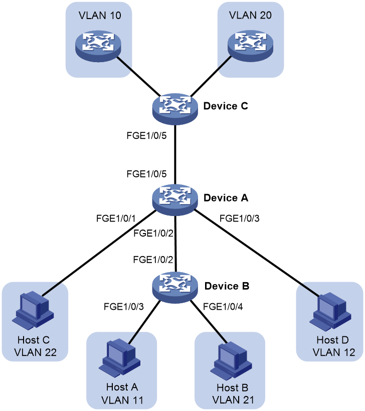
Example: Configuring trunk promiscuous and trunk secondary ports
Network configuration
As shown in Figure 9, configure the private VLAN feature to meet the following requirements:
· VLANs 10 and 20 are primary VLANs on Device A. The uplink port (FortyGigE 1/0/5) on Device A permits the packets from VLANs 10 and 20 to pass through tagged.
· VLANs 11, 12, 21, and 22 are secondary VLANs on Device A.
¡ Downlink port FortyGigE 1/0/2 permits the packets from secondary VLANs 11 and 21 to pass through tagged.
¡ Downlink port FortyGigE 1/0/1 permits secondary VLAN 22.
¡ Downlink port FortyGigE 1/0/3 permits secondary VLAN 12.
· Secondary VLANs 11 and 12 are associated with primary VLAN 10.
· Secondary VLANs 21 and 22 are associated with primary VLAN 20.
Procedure
|
|
IMPORTANT: By default, interfaces on the device are disabled (in ADM or Administratively Down state). To have an interface operate, you must use the undo shutdown command to enable that interface. |
1. Configure Device A:
# Configure VLANs 10 and 20 as primary VLANs.
<DeviceA> system-view
[DeviceA] vlan 10
[DeviceA-vlan10] private-vlan primary
[DeviceA-vlan10] quit
[DeviceA] vlan 20
[DeviceA-vlan20] private-vlan primary
[DeviceA-vlan20] quit
# Create VLANs 11, 12, 21, and 22.
[DeviceA] vlan 11 to 12
[DeviceA] vlan 21 to 22
# Associate secondary VLANs 11 and 12 with primary VLAN 10.
[DeviceA] vlan 10
[DeviceA-vlan10] private-vlan secondary 11 12
[DeviceA-vlan10] quit
# Associate secondary VLANs 21 and 22 with primary VLAN 20.
[DeviceA] vlan 20
[DeviceA-vlan20] private-vlan secondary 21 22
[DeviceA-vlan20] quit
# Configure the uplink port (FortyGigE 1/0/5) as a trunk promiscuous port of VLANs 10 and 20.
[DeviceA] interface fortygige 1/0/5
[DeviceA-FortyGigE1/0/5] port private-vlan 10 20 trunk promiscuous
[DeviceA-FortyGigE1/0/5] quit
# Assign downlink port FortyGigE 1/0/1 to VLAN 22 and configure the port as a host port.
[DeviceA] interface fortygige 1/0/1
[DeviceA-FortyGigE1/0/1] port access vlan 22
[DeviceA-FortyGigE1/0/1] port private-vlan host
[DeviceA-FortyGigE1/0/1] quit
# Assign downlink port FortyGigE 1/0/3 to VLAN 12 and configure the port as a host port.
[DeviceA] interface fortygige 1/0/3
[DeviceA-FortyGigE1/0/3] port access vlan 12
[DeviceA-FortyGigE1/0/3] port private-vlan host
[DeviceA-FortyGigE1/0/3] quit
# Configure downlink port FortyGigE 1/0/2 as a trunk secondary port of VLANs 11 and 21.
[DeviceA] interface fortygige 1/0/2
[DeviceA-FortyGigE1/0/2] port private-vlan 11 21 trunk secondary
[DeviceA-FortyGigE1/0/2] quit
2. Configure Device B:
# Create VLANs 11 and 21.
<DeviceB> system-view
[DeviceB] vlan 11
[DeviceB-vlan11] quit
[DeviceB] vlan 21
[DeviceB-vlan21] quit
# Configure FortyGigE 1/0/2 as a hybrid port, and assign it to VLANs 11 and 21 as a tagged VLAN member.
[DeviceB] interface fortygige 1/0/2
[DeviceB-FortyGigE1/0/2] port link-type hybrid
[DeviceB-FortyGigE1/0/2] port hybrid vlan 11 21 tagged
[DeviceB-FortyGigE1/0/2] quit
# Assign FortyGigE 1/0/3 to VLAN 11.
[DeviceB] interface fortygige 1/0/3
[DeviceB-FortyGigE1/0/3] port access vlan 11
[DeviceB-FortyGigE1/0/3] quit
# Assign FortyGigE 1/0/4 to VLAN 21.
[DeviceB] interface fortygige 1/0/4
[DeviceB-FortyGigE1/0/4] port access vlan 21
[DeviceB-FortyGigE1/0/4] quit
3. Configure Device C:
# Create VLANs 10 and 20.
<DeviceC> system-view
[DeviceC] vlan 10
[DeviceC-vlan10] quit
[DeviceC] vlan 20
[DeviceC-vlan20] quit
# Configure FortyGigE 1/0/5 as a hybrid port, and assign it to VLANs 10 and 20 as a tagged VLAN member.
[DeviceC] interface fortygige 1/0/5
[DeviceC-FortyGigE1/0/5] port link-type hybrid
[DeviceC-FortyGigE1/0/5] port hybrid vlan 10 20 tagged
[DeviceC-FortyGigE1/0/5] quit
Verifying the configuration
# Verify the primary VLAN configurations on Device A. The following output uses primary VLAN 10 as an example.
[DeviceA] display private-vlan 10
Primary VLAN ID: 10
Secondary VLAN ID: 11-12
VLAN ID: 10
VLAN type: Static
Private-vlan type: Primary
Route interface: Not configured
Description: VLAN 0010
Name: VLAN 0010
Tagged ports:
FortyGigE1/0/2
FortyGigE1/0/5
Untagged ports:
FortyGigE1/0/3
VLAN ID: 11
VLAN type: Static
Private-vlan type: Secondary
Route interface: Not configured
Description: VLAN 0011
Name: VLAN 0011
Tagged ports:
FortyGigE1/0/2
FortyGigE1/0/5
Untagged ports: None
VLAN ID: 12
VLAN type: Static
Private-vlan type: Secondary
Route interface: Not configured
Description: VLAN 0012
Name: VLAN 0012
Tagged ports:
FortyGigE1/0/5
Untagged ports:
FortyGigE1/0/3
The output shows that:
· The trunk promiscuous port (FortyGigE 1/0/5) is a tagged member of primary VLAN 10 and secondary VLANs 11 and 12.
· The trunk secondary port (FortyGigE 1/0/2) is a tagged member of primary VLAN 10 and secondary VLAN 11.
· The host port (FortyGigE 1/0/3) is an untagged member of primary VLAN 10 and secondary VLAN 12.
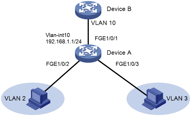
Example: Configuring Layer 3 communication for secondary VLANs
Network configuration
As shown in Figure 10, configure the private VLAN feature to meet the following requirements:
· Primary VLAN 10 on Device A is associated with secondary VLANs 2 and 3. The IP address of VLAN-interface 10 is 192.168.1.1/24.
· FortyGigE 1/0/1 belongs to VLAN 10. FortyGigE 1/0/2 and FortyGigE 1/0/3 belong to VLAN 2 and VLAN 3, respectively.
· Secondary VLANs are isolated at Layer 2 but interoperable at Layer 3.
Procedure
|
|
IMPORTANT: By default, interfaces on the device are disabled (in ADM or Administratively Down state). To have an interface operate, you must use the undo shutdown command to enable that interface. |
# Create VLAN 10 and configure it as a primary VLAN.
<DeviceA> system-view
[DeviceA] vlan 10
[DeviceA-vlan10] private-vlan primary
[DeviceA-vlan10] quit
# Create VLANs 2 and 3.
<DeviceA> system-view
[DeviceA] vlan 2 to 3
# Associate primary VLAN 10 with secondary VLANs 2 and 3.
[DeviceA] vlan 10
[DeviceA-vlan10] private-vlan primary
[DeviceA-vlan10] private-vlan secondary 2 3
[DeviceA-vlan10] quit
# Configure the uplink port (FortyGigE 1/0/1) as a promiscuous port of VLAN 10.
[DeviceA] interface fortygige 1/0/1
[DeviceA-FortyGigE1/0/1] port private-vlan 10 promiscuous
[DeviceA-FortyGigE1/0/1] quit
# Assign downlink port FortyGigE 1/0/2 to VLAN 2, and configure the port as a host port.
[DeviceA] interface fortygige 1/0/2
[DeviceA-FortyGigE1/0/2] port access vlan 2
[DeviceA-FortyGigE1/0/2] port private-vlan host
[DeviceA-FortyGigE1/0/2] quit
# Assign downlink port FortyGigE 1/0/3 to VLAN 3, and configure the port as a host port.
[DeviceA] interface fortygige 1/0/3
[DeviceA-FortyGigE1/0/3] port access vlan 3
[DeviceA-FortyGigE1/0/3] port private-vlan host
[DeviceA-FortyGigE1/0/3] quit
# Enable Layer 3 communication between secondary VLANs 2 and 3 that are associated with primary VLAN 10.
[DeviceA] interface vlan-interface 10
[DeviceA-Vlan-interface10] private-vlan secondary 2 3
# Assign IP address 192.168.1.1/24 to VLAN-interface 10.
[DeviceA-Vlan-interface10] ip address 192.168.1.1 255.255.255.0
# Enable local proxy ARP on VLAN-interface 10.
[DeviceA-Vlan-interface10] local-proxy-arp enable
[DeviceA-Vlan-interface10] quit
Verifying the configuration
# Display the configuration of primary VLAN 10.
[DeviceA] display private-vlan 10
Primary VLAN ID: 10
Secondary VLAN ID: 2-3
VLAN ID: 10
VLAN type: Static
Private VLAN type: Primary
Route interface: Configured
IPv4 address: 192.168.1.1
IPv4 subnet mask: 255.255.255.0
Description: VLAN 0010
Name: VLAN 0010
Tagged ports: None
Untagged ports:
FortyGigE1/0/1
FortyGigE1/0/2
FortyGigE1/0/3
VLAN ID: 2
VLAN type: Static
Private VLAN type: Secondary
Route interface: Configured
IPv4 address: 192.168.1.1
IPv4 subnet mask: 255.255.255.0
Description: VLAN 0002
Name: VLAN 0002
Tagged ports: None
Untagged ports:
FortyGigE1/0/1
FortyGigE1/0/2
VLAN ID: 3
VLAN type: Static
Private VLAN type: Secondary
Route interface: Configured
IPv4 address: 192.168.1.1
IPv4 subnet mask: 255.255.255.0
Description: VLAN 0003
Name: VLAN 0003
Tagged ports: None
Untagged ports:
FortyGigE1/0/1
FortyGigE1/0/3
The Route interface field in the output is Configured, indicating that secondary VLANs 2 and 3 are interoperable at Layer 3.
