- Table of Contents
-
- H3C Anchor Access Points in AC Mode Configuration Examples-6W100
- 00-Preface
- 01-H3C Anchor AC Mode Local Forwarding Configuration Examples
- 02-H3C Anchor AC Mode Dual-Link Backup Configuration Examples
- 03-H3C Anchor AC Mode Internal-to-External Access Through NAT Configuration Examples
- 04-H3C Anchor AC Mode Remote Portal Auth in Local Forwarding Configuration Examples
- 05-H3C Anchor AC Mode Remote Portal Auth in Centralized Forwarding Configuration Examples
- 06-H3C Anchor AC Mode Remote 802.1X Auth in Local Forwarding Configuration Examples
- 07-H3C Anchor AC Mode Remote 802.1X Auth in Centralized Forwarding Configuration Examples
- 08-H3C Anchor AC Mode Remote AP Configuration Examples
- Related Documents
-
| Title | Size | Download |
|---|---|---|
| 06-H3C Anchor AC Mode Remote 802.1X Auth in Local Forwarding Configuration Examples | 367.79 KB |
|
|
|
H3C Anchor Access Points in AC Mode |
|
Remote 802.1X Authentication (Local Forwarding Deployment) Configuration Examples |
|
|
Copyright © 2022 New H3C Technologies Co., Ltd. All rights reserved.
No part of this manual may be reproduced or transmitted in any form or by any means without prior written consent of New H3C Technologies Co., Ltd.
Except for the trademarks of New H3C Technologies Co., Ltd., any trademarks that may be mentioned in this document are the property of their respective owners.
The information in this document is subject to change without notice.
Contents
Example: Configuring remote 802.1X authentication
Editing the AP configuration file
Configuring the anchor AP in AC mode
Introduction
The following information provides an example for configuring remote 802.1X authentication when an anchor AP acts as an AC in a local forwarding mode deployment. In this deployment mode, fit APs act as data traffic forwarders for clients.
Prerequisites
The following information applies to Comware 7-based access controllers and access points. Procedures and information in the examples might be slightly different depending on the software or hardware version of the devices.
The configuration examples were created and verified in a lab environment, and all the devices were started with the factory default configuration. When you are working on a live network, make sure you understand the potential impact of every command on your network.
The following information is provided based on the assumption that you have basic knowledge of AAA, 802.1X, and WLAN access.
Example: Configuring remote 802.1X authentication
The AC in this example is an anchor AP that acts as an AC.
Network configuration
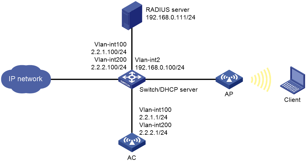
As shown in Figure 1:
· The switch acts as a DHCP server to assign IP addresses to the AP and the client.
· Establish the CAPWAP tunnels between the AC and the AP in VLAN 100.
· Connect the client to the WLAN network in VLAN 200.
· Use IMC as the RADIUS server to do authentication, authorization, and accounting for the client.
Configure the network to meet the following requirements:
· The AP forwards the data traffic from the client directly.
· Use 802.1X AKM to authenticate clients and protect data transmission between the clients and the AP.
· The IMC server dynamically changes the authorization for the client or forces the client offline.
Analysis
· To have the AP forward client data traffic in VLAN 200 on GigabitEthernet 1/0/1, edit a .txt configuration file to add the port to VLAN 200 and upload the file to the AC.
· For the RADIUS server to dynamically change client authorization or force clients offline, you must enable the RADIUS session-control feature on the AC.
· To do dynamic authorization for clients, configure the AC as a RADIUS DAE server (DAS).
Restrictions and guidelines
· Make sure the fit APs deployed on the network are compatible with the anchor AP (the AC in this document).
· Use the serial ID labeled on the AP's rear panel to specify an AP.
Procedures
Configuring the switch
Configuring interfaces on the switch
# Create VLAN 100 to transport the traffic in the CAPWAP tunnels between the AC and the AP.
<Switch> system-view
[Switch] vlan 100
[Switch-vlan100] quit
# Create VLAN 200 to transport radio packets for the client.
[Switch] vlan 200
[Switch-vlan200] quit
# Create VLAN 2 for establishing connectivity to the IMC server.
[Switch] vlan 2
[Switch-vlan2] quit
# Create VLAN-interface 100 and assign an IP address to it.
[Switch] interface vlan-interface 100
[Switch-Vlan-interface100] ip address 2.2.1.100 255.255.255.0
[Switch-Vlan-interface100] quit
# Create VLAN-interface 200 and assign an IP address to it.
[Switch] interface vlan-interface 200
[Switch-Vlan-interface200] ip address 2.2.2.100 255.255.255.0
[Switch-Vlan-interface200] quit
# Create VLAN-interface 2 and assign an IP address to it.
[Switch] interface vlan-interface 2
[Switch-Vlan-interface2] ip address 192.168.0.100 255.255.255.0
[Switch-Vlan-interface2] quit
# Assign the interface connected to the RADIUS server to VLAN 2. (Details not shown.)
# Configure GigabitEthernet 1/0/1 (the port connected to the AC) as a trunk port and assign it to VLANs 100 and 200.
[Switch] interface gigabitethernet 1/0/1
[Switch-GigabitEthernet1/0/1] port link-type trunk
[Switch-GigabitEthernet1/0/1] port trunk permit vlan 100 200
[Switch-GigabitEthernet1/0/1] quit
# Configure GigabitEthernet 1/0/2 (the port connected to the AP) as a trunk port, assign it to VLANs 100 and 200, and set its PVID to VLAN 100.
[Switch] interface gigabitethernet 1/0/2
[Switch-GigabitEthernet1/0/2] port link-type trunk
[Switch-GigabitEthernet1/0/2] port trunk permit vlan 100 200
[Switch-GigabitEthernet1/0/2] port trunk pvid vlan 100
# Enable PoE.
[Switch-GigabitEthernet1/0/2] poe enable
[Switch-GigabitEthernet1/0/2] quit
Configuring the DHCP server
# Enable DHCP.
[Switch] dhcp enable
# Configure DHCP address pool 100 to assign IP addresses to APs. Specify 2.2.1.100 as a gateway address in the address pool.
[Switch] dhcp server ip-pool 100
[Switch-dhcp-pool-100] network 2.2.1.0 mask 255.255.255.0
[Switch-dhcp-pool-100] gateway-list 2.2.1.100
[Switch-dhcp-pool-100] forbidden-ip 2.2.1.1
[Switch-dhcp-pool-100] quit
# Configure DHCP address pool 200 to assign IP addresses to clients. In this example, the DNS server address is the same as the gateway address in the address pool. You must replace it with the actual address of the DNS server on your network.
[Switch] dhcp server ip-pool 200
[Switch-dhcp-pool-200] network 2.2.2.0 mask 255.255.255.0
[Switch-dhcp-pool-200] gateway-list 2.2.2.100
[Switch-dhcp-pool-200] dns-list 2.2.2.100
[Switch-dhcp-pool-200] forbidden-ip 2.2.2.1
[Switch-dhcp-pool-200] quit
# Configure the interface connected to the external network and the default route. (Details not shown.)
Editing the AP configuration file
# Use a text editor to edit the APs' configuration file, and then upload the file to the central AC. In this example, the configuration file name is map.txt. The following is the AP configuration for this example:
system-view
vlan 200
interface gigabitethernet1/0/1
port link-type trunk
port trunk permit vlan 200
Configuring the anchor AP in AC mode
Configuring interfaces on the AC
# Create VLAN 100 and VLAN-interface 100, and assign an IP address to the VLAN interface. The AC will use this IP address to establish CAPWAP tunnels with the AP.
<AC> system-view
[AC] vlan 100
[AC-vlan100] quit
[AC] interface vlan-interface 100
[AC-Vlan-interface100] ip address 2.2.1.1 24
[AC-Vlan-interface100] quit
# Create VLAN 200 and VLAN-interface 200, and assign an IP address to the VLAN interface. The client will be assigned to this VLAN.
[AC] vlan 200
[AC-vlan200] quit
[AC] interface vlan-interface 200
[AC-Vlan-interface200] ip address 2.2.2.1 24
[AC-Vlan-interface200] quit
# Configure GigabitEthernet 1/0/1 (the port connected to the switch) as a trunk port and assign it to VLANs 100 and 200.
[AC] interface gigabitethernet 1/0/1
[AC-GigabitEthernet1/0/1] port link-type trunk
[AC-GigabitEthernet1/0/1] port trunk permit vlan 100 200
[AC-GigabitEthernet1/0/1] quit
Configuring static routing
# Configure a static route to IMC (the RADIUS servers).
[AC] ip route-static 192.168.0.0 255.255.255.0 2.2.2.100
Configuring a RADIUS scheme
# Create a RADIUS scheme named radius1 and enter its view.
[AC] radius scheme radius1
# Specify the IP addresses of the primary authentication and accounting RADIUS servers.
[AC-radius-radius1] primary authentication 192.168.0.111
[AC-radius-radius1] primary accounting 192.168.0.111
# Set the shared key to radius in plain text for secure communication with the servers.
[AC-radius-radius1] key authentication simple radius
[AC-radius-radius1] key accounting simple radius
# Specify IP address 2.2.2.1 as the source IP address of outgoing RADIUS packets.
[AC-radius-radius1] nas-ip 2.2.2.1
[AC-radius-radius1] quit
# Enable the RADIUS session-control feature.
[AC] radius session-control enable
# Enable the RADIUS DAS feature and enter RADIUS DAS view.
[AC] radius dynamic-author server
# Specify the RADIUS server at 192.168.0.111 as a DAC and set the shared key to radius in plain text for validating DAE packets from the RADIUS server.
[AC-radius-da-server] client ip 192.168.0.111 key simple radius
[AC-radius-da-server] quit
Configuring the authentication domain
# Create an ISP domain named dm1 and enter its view.
[AC] domain dm1
# Apply RADIUS scheme radius1 to the ISP domain for LAN user authentication, authorization, and accounting.
[AC-isp-dm1] authentication lan-access radius-scheme radius1
[AC-isp-dm1] authorization lan-access radius-scheme radius1
[AC-isp-dm1] accounting lan-access radius-scheme radius1
# Configure the idle-cut feature to disconnect idle users in the domain. Users are considered idle if they fail to generate a minimum amount of traffic over a period set by the idle-cut timer. In this example, set the idle-cut timer to 15 minutes and the minimum traffic to 1024 bytes.
[AC-isp-dm1] authorization-attribute idle-cut 15 1024
[AC-isp-dm1] quit
Configuring 802.1X authentication
# Configure EAP relay as the method for the AC to exchange packets with the RADIUS server.
[AC] dot1x authentication-method eap
Configuring a service template
# Create service template st1 and enter its view.
[AC] wlan service-template st1
# Set the SSID of the service template to service.
[AC-wlan-st-st1] ssid service
# Assign VLAN 200 to the matching clients.
[AC-wlan-st-st1] vlan 200
# Set the AKM mode to 802.1X, specify the CCMP cipher suite, and enable the RSN IE in beacon and probe responses.
[AC-wlan-st-st1] akm mode dot1x
[AC-wlan-st-st1] cipher-suite ccmp
[AC-wlan-st-st1] security-ie rsn
# Set the access authentication mode to 802.1X and the ISP domain to dm1 for the matching clients.
[AC-wlan-st-st1] client-security authentication-mode dot1x
[AC-wlan-st-st1] dot1x domain dm1
# Specify APs as client data traffic forwarders.
[AC–wlan-st-st1] client forwarding-location ap
# Enable the service template.
[AC-wlan-st-st1] service-template enable
[AC-wlan-st-st1] quit
# Create an AP named office and specify its AP model and serial ID. In this example, the AP model is WA6638 and its serial ID is 219801A24F8198E00042.
[AC] wlan ap office model WA6638
[AC-wlan-ap-office] serial-id 219801A24F8198E00042
# Deploy the map.txt configuration file to the AP.
[AC-wlan-ap-office] map-configuration map.txt
# Enter the view of radio 1.
[AC-wlan-ap-office] radio 1
# Bind service template st1 to radio 1, and then enable the radio.
[AC-wlan-ap-office-radio-1] service-template st1
[AC-wlan-ap-office-radio-1] radio enable
[AC-wlan-ap-office-radio-1] quit
[AC-wlan-ap-office] quit
Configuring the RADIUS server
This example uses IMC as the RADIUS server, which runs PLAT 7.1(E0303p13), IMC EIA 7.1(F0302p08), and EIP 7.1(F0302p08).
Adding the AC to IMC as an access device
1. Log in to IMC and click the User tab.
2. From the navigation pane, select User Access Policy > Access Device Management > Access Device.
3. Click Add.
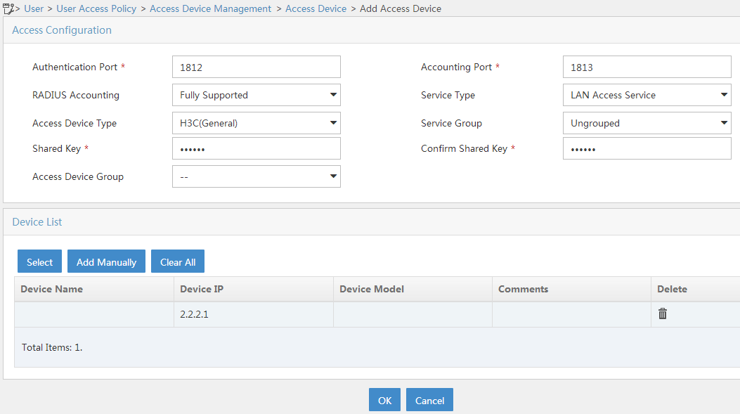
4. On the Add Access Device page that opens, add the AC as an access device to IMC:
a. In the Access Configuration area, enter radius in the Shared Key and Confirm Shared Key fields. Use the default values for other parameters.
The shared key must be the same as the authentication and accounting shared keys configured on the central AC.
b. In the Device List area, click Select or Add Manually to add the AC at 2.2.2.1 as an access device.
The IP address must be the NAS IP specified in the RADIUS scheme on the AC.
c. Click OK.
Figure 2 Adding the AC to IMC as an access device
Adding an access policy
1. Click the User tab.
2. From the navigation pane, select User Access Policy > Access Policy.
3. Click Add.
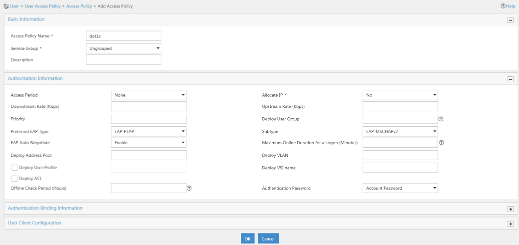
4. On the page that opens, add the access policy:
a. Enter the access policy name.
b. Select EAP-PEAP from the Preferred EAP Type list, and select EAP-MSCHAPv2 from the Subtype list.
The certificate subtype on the IMC server must be the same as the identity authentication method configured on the clients.
Use the default values for other parameters.
Figure 3 Adding an access policy
Adding an access service
1. Click the User tab.
2. From the navigation pane, select User Access Policy > Access Service.
3. Click Add.
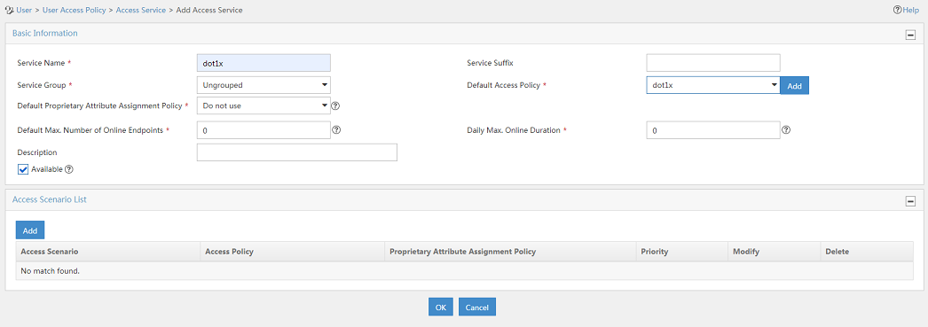
4. On the Add Access Service page, add the access service:
a. Enter dot1x in the Service Name field.
b. Select dot1x (the access policy you have created) from the Default Access Policy list.
Use the default values for other parameters.
Figure 4 Adding an access service
Adding an access user
1. Click the User tab.
2. From the navigation pane, select Access User > All Access Users.
3. Click Add.
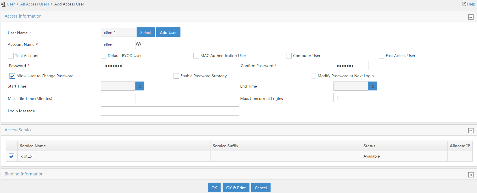
4. On the page that opens, add the client as an access user:
a. If the user has been added to the platform, click Select to select that user. If the user has not been added to the platform, click Add User to add the user to the platform.
b. Enter the access user account name for the user in the Account Name field and set a password for the account. In this example, the account name for the user is client and the password is dot1x11.
c. Bind the access user account to the access service you have created.
Use the default values for other parameters.
Figure 5 Adding an access user
Configuring the client
Access the WLAN from a mobile phone
Search for WLAN networks and connect to the WLAN named service:
· Select 801.1X EAP for security, set the EAP method to PEAP, set phase 2 authentication to MSCHAPv2, and select None for the CA certificate.
· Enter the username and password to authenticate to the network. In this example, the username is client and the password is dot1x11.
· Use the default values for other parameters.
Accessing the WLAN from a PC
The following information uses Windows 7 for example to describe the wireless adapter configuration procedure.
1. Access the window for wireless network management:
a. Click the Start menu icon, and then select the Control Panel option.
b. Under Network and Internet, click View network status and tasks.
c. In the Network and Sharing Center window, select Manage wireless networks.
2. In the window that opens, click Add, and then select Manually create a network profile.
3. In the wizard that opens, add the WLAN settings:
¡ Set the network name to 1X.
¡ Set the security type to WPA2-Enterprise.
¡ Set the encryption type to AES.
¡ Use the default values for other parameters.
¡ Click Next.
4. After the network is created, select Change connection settings to configure security attributes for the network.
5. In the dialog box that opens, configure the security attributes for the network:
a. Click the Security tab.
b. Select Microsoft: Protected EAP (PEAP) from the Choose a network authentication method list.
c. Clear the Remember my credentials for this connection each time I’m logged on option.
6. Click Settings to configure PEAP properties, as follows:
¡ Clear the Validate server certificate option.
¡ Clear the Enable Fast Reconnect option.
¡ Click the Configure button next to the option for the Select Authentication Method field.
¡ In the EAP MSCHAPv2 Properties dialog box that opens, clear the Automatically use my Windows logon name and password option, and then click OK.
7. In the Protected EAP Properties dialog box, click OK.
8. Configure advanced 802.1X and 802.11 settings:
a. In the Wireless Network Properties dialog box, click Advanced Settings.
b. On the 802.1X settings tab, select the Specify authentication mode option, and then select User authentication from the authentication mode list.
c. Click the 802.11 settings tab, clear the Enable Pairwise Master Key (PMK) caching option, and then click OK.
9. Connect to the WLAN network named service.
10. On the authentication page that opens, enter the username and password to authenticate to the network. In this example, the username is client and the password is dot1x11.
Verifying the configuration
Verify that the client can pass 802.1X authentication and associate with the AP to access the network.
# Execute the display wlan client verbose command on the AC to verify the online state of the client.
[AC] display wlan client verbose
Total number of clients: 1
MAC address : cc3a-61a8-fb8c
IPv4 address : 2.2.2.3
IPv6 address : N/A
Username : client
AID : 1
AP ID : 3
AP name : office
Radio ID : 1
SSID : service
BSSID : 741f-4ad4-1fe0
VLAN ID : 200
Sleep count : 0
Wireless mode : 802.11ax
Channel bandwidth : 80MHz
SM power save : Disabled
Short GI for 20MHz : Supported
Short GI for 40MHz : Supported
Short GI for 80MHz : Supported
Short GI for 160/80+80MHz : Not supported
STBC RX capability : Supported
STBC TX capability : Supported
LDPC RX capability : Supported
Beamformee STS capability : N/A
Number of Sounding Dimensions : N/A
SU beamformee capability : Not supported
MU beamformee capability : Not supported
Beamformee STS capability : N/A
Block Ack : N/A
Supported VHT-MCS set : NSS1 0, 1, 2, 3, 4, 5, 6, 7, 8, 9
NSS2 0, 1, 2, 3, 4, 5, 6, 7, 8, 9
Supported HT MCS set : 0, 1, 2, 3, 4, 5, 6, 7
8, 9, 10, 11, 12, 13, 14,
15
Supported rates : 6, 9, 12, 18, 24, 36, 48, 54 Mbps
5G 40And80MHz Channel bandwidth : Supported
5G 160MHz Channel bandwidth : Not Supported
5G 8080MHz Channel bandwidth : Not Supported
OFDMA random access RUs : Not supported
Supported HE-MCS set : NSS1 0, 1, 2, 3, 4, 5, 6, 7, 8, 9, 10, 11
NSS2 0, 1, 2, 3, 4, 5, 6, 7, 8, 9, 10, 11
TWT scheduled : no
QoS mode : WMM
Listen interval : 10
RSSI : 0
Rx/Tx rate : 0/0
Authentication method : Open system
Security mode : RSN
AKM mode : 802.1X
Cipher suite : CCMP
User authentication mode : 802.1X
Authorization ACL ID : N/A
Authorization user profile : N/A
Roam status : N/A
Key derivation : SHA1
PMF status : N/A
Forwarding policy name : N/A
Online time : 0days 0hours 0minutes 15seconds
FT status : Inactive
BTM status : Disabled
# Execute the display dot1x command on the AC to verify the online state of the 802.1X user (the client).
[AC] display dot1x connection
Total connections: 1
User MAC address : cc3a-61a8-fb8c
AP name : office
Radio ID : 1
SSID : service
BSSID : 741f-4ad4-1fe0
Username : client
Authentication domain : dm1
IPv4 address : 2.2.2.3
Authentication method : EAP
Initial VLAN : 200
Authorization VLAN : 200
Authorization ACL number : N/A
Authorization user profile : N/A
Termination action : Default
Session timeout period : 36000001 s
Online from : 2022/05/21 11:27:11
Online duration : 0h 1m 1s
Configuration files
· AC (anchor AP):
#
dot1x authentication-method eap
#
vlan 100
#
vlan 200
#
wlan service-template st1
ssid service
vlan 200
akm mode dot1x
cipher-suite ccmp
security-ie rsn
client-security authentication-mode dot1x
dot1x domain dm1
service-template enable
#
interface Vlan-interface100
ip address 2.2.1.1 255.255.255.0
#
interface Vlan-interface200
ip address 2.2.2.1 255.255.255.0
#
interface GigabitEthernet1/0/1
port link-type trunk
port trunk permit vlan 1 100 200
#
ip route-static 192.168.0.0 24 2.2.2.100
#
radius session-control enable
#
radius scheme radius1
primary authentication 192.168.0.111
primary accounting 192.168.0.111
key authentication cipher $c$3$Sqgqz7lDs4XPnethmAgyAKVlke7qwEkYbQ==
key accounting cipher $c$3$4J/JBRGwqB4F213furJMkB6JWYXBFjWE6g==
nas-ip 2.2.2.1
#
radius dynamic-author server
client ip 192.168.0.111 key cipher $c$3$AkTEB7OgMYnCqsfDeplhoAgXUek/rVrLZw==
#
domain dm1
authorization-attribute idle-cut 15 1024
authentication lan-access radius-scheme radius1
authorization lan-access radius-scheme radius1
accounting lan-access radius-scheme radius1
#
wlan ap office model WA6638
serial-id 219801A24F8198E00042
map-configuration flash:/map.txt
radio 1
radio enable
service-template st1
radio 2
#
· Switch:
#
dhcp enable
#
vlan 2
#
vlan 100
#
vlan 200
#
dhcp server ip-pool 100
gateway-list 2.2.1.100
network 2.2.1.0 mask 255.255.255.0
forbidden-ip 2.2.1.1
#
dhcp server ip-pool 200
gateway-list 2.2.2.100
network 2.2.2.0 mask 255.255.255.0
dns-list 2.2.2.100
forbidden-ip 2.2.2.1
#
interface Vlan-interface2
ip address 192.168.0.100 255.255.255.0
#
interface Vlan-interface100
ip address 2.2.1.100 255.255.255.0
#
interface Vlan-interface200
ip address 2.2.2.100 255.255.255.0
#
interface GigabitEthernet1/0/1
port link-type trunk
port trunk permit vlan 1 100 200
#
interface GigabitEthernet1/0/2
port link-type trunk
port trunk permit vlan 1 100 200
port trunk pvid vlan 100
poe enable
#
Related documentation
· User Access and Authentication Configuration Guide in H3C Access Points Anchor AC Mode Configuration Guides
· User Access and Authentication Command Reference in H3C Access Points Anchor AC Mode Command Reference
· WLAN Access Configuration Guide in H3C Access Points Anchor AC Mode Configuration Guides
· WLAN Access Command Reference in H3C Access Points Anchor AC Mode Command Reference