- Table of Contents
-
- H3C Anchor Access Points in AC Mode Configuration Examples-6W100
- 00-Preface
- 01-H3C Anchor AC Mode Local Forwarding Configuration Examples
- 02-H3C Anchor AC Mode Dual-Link Backup Configuration Examples
- 03-H3C Anchor AC Mode Internal-to-External Access Through NAT Configuration Examples
- 04-H3C Anchor AC Mode Remote Portal Auth in Local Forwarding Configuration Examples
- 05-H3C Anchor AC Mode Remote Portal Auth in Centralized Forwarding Configuration Examples
- 06-H3C Anchor AC Mode Remote 802.1X Auth in Local Forwarding Configuration Examples
- 07-H3C Anchor AC Mode Remote 802.1X Auth in Centralized Forwarding Configuration Examples
- 08-H3C Anchor AC Mode Remote AP Configuration Examples
- Related Documents
-
| Title | Size | Download |
|---|---|---|
| 02-H3C Anchor AC Mode Dual-Link Backup Configuration Examples | 80.27 KB |
|
|
|
H3C Anchor Access Points in AC Mode |
|
Dual-Link Backup Configuration Examples |
|
|
|
|
Copyright © 2022 New H3C Technologies Co., Ltd. All rights reserved.
No part of this manual may be reproduced or transmitted in any form or by any means without prior written consent of New H3C Technologies Co., Ltd.
Except for the trademarks of New H3C Technologies Co., Ltd., any trademarks that may be mentioned in this document are the property of their respective owners.
The information in this document is subject to change without notice.
Overview
The following information provides an example for configuring dual-link backup by using anchor APs that act as ACs.
Prerequisites
The following information applies to Comware 7-based access controllers and access points. Procedures and information in the examples might be slightly different depending on the software or hardware version of the access controllers and access points.
The configuration examples were created and verified in a lab environment, and all the devices were started with the factory default configuration. When you are working on a live network, make sure you understand the potential impact of every command on your network.
The following information is provided based on the assumption that you have basic knowledge of AP management and WLAN high availability.
Example: Configuring dual-link AC backup
The AC in this example is an anchor AP that operates as an AC.
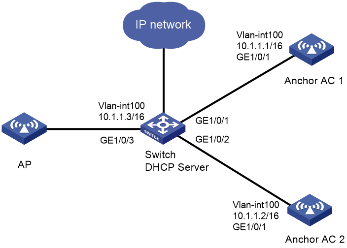
Network configuration
As shown in Figure 1, the AP connects to AC 1 and AC 2 through the switch.
Configure dual-link backup and specify AC 1 as the master AC and AC 2 as the backup AC. When AC 1 fails, master/backup AC switchover occurs and the AP communicates through AC 2. When AC 1 recovers, AC 1 takes over services again.
|
|
NOTE: Dual-link backup is supported by both local and centralized forwarding. This example uses centralized forwarding. |
Restrictions and guidelines
When you configure dual-link backup, follow these restrictions and guidelines:
· Make sure the two ACs are of the same model and uses the same software version.
· Use the serial ID labeled on the AP's rear panel to specify an AP.
· If you configure manual APs, make sure the manual APs configured on the two ACs have the same AP name and identifier (serial ID or MAC address).
Procedures
Configuring AC 1
1. Configure AC interfaces:
# Create VLAN 100 and VLAN-interface 100. Assign the VLAN interface an IP address. The AC will use this IP address to establish a CAPWAP tunnel with the AP.
<AC1> system-view
[AC1] vlan 100
[AC1-vlan100] quit
[AC1] interface vlan-interface 100
[AC1-Vlan-interface100] ip address 10.1.1.1 16
[AC1-Vlan-interface100] quit
# Create VLAN 200 and VLAN-interface 200. Assign the VLAN interface an IP address. Clients will use this VLAN to access the WLAN.
[AC1] vlan 200
[AC1-vlan200] quit
[AC1] interface vlan-interface 200
[AC1-Vlan-interface200] ip address 10.2.1.1 16
[AC1-Vlan-interface200] quit
# Configure GigabitEthernet 1/0/1 that connects AC 1 to the switch as a trunk port, and assign it to VLAN 100 and VLAN 200.
[AC1] interface gigabitethernet 1/0/1
[AC1-GigabitEthernet1/0/1] port link-type trunk
[AC1-GigabitEthernet1/0/1] port trunk permit vlan 100 200
[AC1-GigabitEthernet1/0/1] quit
2. Configure dual-link backup:
# Create AP group group1 and set the AP connection priority to 7.
[AC1] wlan ap-group group1
[AC1-wlan-ap-group-group1] priority 7
# Specify AC 2 as the backup AC for AC 1.
[AC1-wlan-ap-group-group1] backup-ac ip 10.1.1.2
# Enable master CAPWAP tunnel preemption.
[AC1-wlan-ap-group-group1] wlan tunnel-preempt enable
# Add AP ap1 to the group.
[AC1-wlan-ap-group-group1] ap ap1
[AC1-wlan-ap-group-group1] quit
3. Configure wireless services:
# Create service template 1 and enter its view.
[AC1] wlan service-template 1
# Specify the SSID as service.
[AC1-wlan-st-1] ssid service
# Configure centralized forwarding.
[AC1-wlan-st-1] client forwarding-location ac
# Assign clients coming online through the service template to VLAN 200.
[AC1-wlan-st-1] vlan 200
# Specify the AKM as PSK, and specify a plaintext pre-shared key 12345678.
[AC1-wlan-st-1] akm mode psk
[AC1-wlan-st-1] preshared-key pass-phrase simple 12345678
# Specify the cipher suite as CCMP and configure the RSN security IE.
[AC1-wlan-st-1] cipher-suite ccmp
[AC1-wlan-st-1] security-ie rsn
# Enable the service template.
[AC1-wlan-st-1] service-template enable
[AC1-wlan-st-1] quit
4. Configure a manual AP:
# Create AP ap1, and specify the AP model and serial ID.
[AC1] wlan ap ap1 model WA6320
[AC1-wlan-ap-ap1] serial-id 219801A28N819CE0002T
# Bind service template 1 to radio 2 of the AP.
[AC1-wlan-ap-6320] radio 2
[AC1-wlan-ap-6320-radio-2] service-template 1
# Enable the radio.
[AC1-wlan-ap-6320-radio-2] radio enable
[AC1-wlan-ap-6320-radio-2] quit
Configuring AC 2
1. Configure AC interfaces:
# Create VLAN 100 and VLAN-interface 100. Assign the VLAN interface an IP address. The AC will use this IP address to establish a CAPWAP tunnel with the AP.
<AC2> system-view
[AC2] vlan 100
[AC2-vlan100] quit
[AC2] interface Vlan-interface 100
[AC2-Vlan-interface100] ip address 10.1.1.2 16
[AC2-Vlan-interface100] quit
# Create VLAN 200 and VLAN-interface 200. Assign the VLAN interface an IP address. Clients will use this VLAN to access the WLAN.
[AC2] vlan 200
[AC2-vlan200] quit
[AC2] interface vlan-interface 200
[AC2-Vlan-interface200] ip address 10.2.1.2 16
[AC2-Vlan-interface200] quit
# Configure GigabitEthernet 1/0/1 that connects AC 2 to the switch as a trunk port, and assign it to VLAN 100 and VLAN 200.
[AC2] interface gigabitethernet 1/0/1
[AC2-GigabitEthernet1/0/1] port link-type trunk
[AC2-GigabitEthernet1/0/1] port trunk permit vlan 100 200
[AC2-GigabitEthernet1/0/1] quit
2. Configure dual-link backup:
# Create AP group group1, and specify AC 1 as the backup AC for AC 2.
[AC2] wlan ap-group group1
[AC2-wlan-ap-group-group1] backup-ac ip 10.1.1.1
# Add AP ap1 to the group.
[AC2-wlan-ap-group-group1] ap ap1
[AC2-wlan-ap-group-group1] quit
3. Configure wireless services:
# Create service template 1 and enter its view.
[AC2] wlan service-template 1
# Specify the SSID as service.
[AC2-wlan-st-1] ssid service
# Configure centralized forwarding.
[AC2-wlan-st-1] client forwarding-location ac
# Assign clients coming online through the service template to VLAN 200.
[AC2-wlan-st-1] vlan 200
# Specify the AKM as PSK, and specify a plaintext pre-shared key 12345678.
[AC2-wlan-st-1] akm mode psk
[AC2-wlan-st-1] preshared-key pass-phrase simple 12345678
# Specify the cipher suite as CCMP and configure the RSN security IE.
[AC2-wlan-st-1] cipher-suite ccmp
[AC2-wlan-st-1] security-ie rsn
# Enable the service template.
[AC2-wlan-st-1] service-template enable
[AC2-wlan-st-1] quit
4. Configure a manual AP:
# Create AP ap1, and specify the AP model and serial ID.
[AC2] wlan ap ap1 model WA6320
[AC2-wlan-ap-ap1] serial-id 219801A28N819CE0002T
# Bind service template 1 to radio 2 of the AP.
[AC2-wlan-ap-6320] radio 2
[AC2-wlan-ap-6320-radio-2] service-template 1
# Enable the radio.
[AC2-wlan-ap-6320-radio-2] radio enable
[AC2-wlan-ap-6320-radio-2] quit
Configuring the switch
1. Configure switch interfaces:
# Create VLAN 100 for forwarding CAPWAP tunnel traffic between AC and AP.
<Switch> system-view
[Switch] vlan 100
[Switch-vlan100] quit
# Assign an IP address to VLAN-interface 100.
[Switch] interface vlan-interface 100
[Switch-Vlan-interface100] ip address 10.1.1.3 16
[Switch-Vlan-interface100] quit
# Create VLAN 200 for forwarding client traffic, and assign an IP address to VLAN-interface 200.
[Switch] vlan 200
[Switch-vlan200] quit
[Switch] interface vlan-interface 200
[Switch-Vlan-interface200] ip address 10.2.1.3 16
[Switch-Vlan-interface200] quit
# Configure GigabitEthernet 1/0/1 that connects the switch to AC 1 as a trunk port, and assign it to VLAN 100 and VLAN 200.
[Switch] interface gigabitethernet 1/0/1
[Switch-GigabitEthernet1/0/1] port link-type trunk
[Switch-GigabitEthernet1/0/1] port trunk permit vlan 100 200
[Switch-GigabitEthernet1/0/1] quit
# Configure GigabitEthernet 1/0/2 that connects the switch to AC 2 as a trunk port, and assign it to VLAN 100 and VLAN 200.
[Switch] interface gigabitethernet 1/0/2
[Switch-GigabitEthernet1/0/2] port link-type trunk
[Switch-GigabitEthernet1/0/2] port trunk permit vlan 100 200
[Switch-GigabitEthernet1/0/2] quit
# Configure GigabitEthernet 1/0/3 that connects the switch to the AP as an access port, and assign the interface to VLAN 100.
[Switch] interface gigabitethernet 1/0/3
[Switch-GigabitEthernet1/0/3] port link-type access
[Switch-GigabitEthernet1/0/3] port access vlan 100
# Enable PoE.
[Switch-GigabitEthernet1/0/3] poe enable
[Switch-GigabitEthernet1/0/3] quit
2. Configuring the DHCP service:
# Create DHCP address pool 100 for the AP.
[Switch] dhcp server ip-pool 100
[Switch-dhcp-pool-100] network 10.1.0.0 mask 255.255.0.0
[Switch-dhcp-pool-100] quit
# Create DHCP address pool 200 for clients.
[Switch] dhcp server ip-pool 200
[Switch-dhcp-pool-200] network 10.2.0.0 mask 255.255.0.0
[Switch-dhcp-pool-200] quit
# Enable DHCP.
[DHCP Server] dhcp enable
Verifying the configuration
# Associate the AP with AC 1. Shut down VLAN-interface 100 on AC 1, wait a period of time for the CAPWAP tunnel to go down, and verify that the AP associates with AC 2 and the AP state on AC 2 is R/M.
The wait time length depends on the CAPWAP tunnel keepalive time, which is 30 seconds by default. If centralized forwarding is used, service interruption occurs after the tunnel goes down.
<AC2> display wlan ap all
Total number of APs: 1
Total number of connected APs: 1
Total number of connected manual APs: 1
Total number of connected auto APs: 0
Total number of connected common APs: 1
Total number of connected WTUs: 0
Total number of inside APs: 0
Maximum supported APs: 384
Remaining APs: 383
Total AP licenses: 256
Local AP licenses: 256
Server AP licenses: 0
Remaining local AP licenses: 255
AP information
State : I = Idle, J = Join, JA = JoinAck, IL = ImageLoad
C = Config, DC = DataCheck, R = Run M = Master, B = Backup
AP name APID State Model Serial ID
ap1 1 R/M WA6320 219801A28N819CE0002T
# Bring up VLAN-interface 100 on AC 1. Wait about 10 minutes and verify that the AP comes online from AC 1 again and the AP state is R/M on AC 1 and R/B on AC 2.
Configuration files
· AC 1 (anchor AP):
#
vlan 100
#
vlan 200
#
interface Vlan-interface100
ip address 10.1.1.1 255.255.0.0
#
interface Vlan-interface200
ip address 10.2.1.1 255.255.0.0
#
interface GigabitEthernet1/0/1
port link-type trunk
port trunk permit vlan 100 200
#
wlan ap-group group1
priority 7
wlan tunnel-preempt enable
backup-ac ip 10.1.1.2
ap ap1
#
wlan service-template 1
ssid service
vlan 200
client forwarding-location ac
akm mode psk
preshared-key pass-phrase simple 12345678
cipher-suite ccmp
security-ie rsn
service-template enable
#
wlan ap ap1 model WA6320
serial-id 219801A28N819CE0002T
radio 2
radio enable
service-template 1
#
· AC 2 (anchor AP):
#
vlan 100
#
vlan 200
#
interface Vlan-interface100
ip address 10.1.1.2 255.255.0.0
#
interface Vlan-interface200
ip address 10.2.1.2 255.255.0.0
#
interface GigabitEthernet1/0/1
port link-type trunk
port trunk permit vlan 100 200
#
wlan ap-group group1
backup-ac ip 10.1.1.1
ap ap1
#
wlan service-template 1
ssid service
vlan 200
client forwarding-location ac
akm mode psk
preshared-key pass-phrase simple 12345678
cipher-suite ccmp
security-ie rsn
service-template enable
#
wlan ap ap1 model WA6320
serial-id 219801A28N819CE0002T
radio 2
radio enable
service-template 1
#
· Switch:
#
dhcp enable
#
vlan 100
#
vlan 200
#
dhcp server ip-pool 100
network 10.1.0.0 mask 255.255.0.0
#
dhcp server ip-pool 200
network 10.2.0.0 mask 255.255.0.0
#
interface Vlan-interface100
ip address 10.1.1.3 255.255.0.0
#
interface Vlan-interface200
ip address 10.2.1.3 255.255.0.0
#
interface GigabitEthernet1/0/1
port link-type trunk
port trunk permit vlan all
#
interface GigabitEthernet1/0/2
port link-type trunk
port trunk permit vlan all
#
interface GigabitEthernet1/0/3
port link-type access
port access vlan 100
poe enable
#
Related documentation
· AP Management Command Reference in H3C Access Points Anchor AC Mode Command References
· AP Management Configuration Guide in H3C Access Points Anchor AC Mode Configuration Guides
· WLAN High Availability Command Reference in H3C Access Points Anchor AC Mode Command References
· WLAN High Availability Configuration Guide in H3C Access Points Anchor AC Mode Configuration Guides