- Table of Contents
-
- H3C Anchor Access Points in AC Mode Configuration Examples-6W100
- 00-Preface
- 01-H3C Anchor AC Mode Local Forwarding Configuration Examples
- 02-H3C Anchor AC Mode Dual-Link Backup Configuration Examples
- 03-H3C Anchor AC Mode Internal-to-External Access Through NAT Configuration Examples
- 04-H3C Anchor AC Mode Remote Portal Auth in Local Forwarding Configuration Examples
- 05-H3C Anchor AC Mode Remote Portal Auth in Centralized Forwarding Configuration Examples
- 06-H3C Anchor AC Mode Remote 802.1X Auth in Local Forwarding Configuration Examples
- 07-H3C Anchor AC Mode Remote 802.1X Auth in Centralized Forwarding Configuration Examples
- 08-H3C Anchor AC Mode Remote AP Configuration Examples
- Related Documents
-
| Title | Size | Download |
|---|---|---|
| 04-H3C Anchor AC Mode Remote Portal Auth in Local Forwarding Configuration Examples | 374.38 KB |
|
|
|
H3C Anchor Access Points in AC Mode |
|
Remote Portal Authentication (Local Forwarding Deployment) Configuration Examples |
|
|
|
|
Copyright © 2022 New H3C Technologies Co., Ltd. All rights reserved.
No part of this manual may be reproduced or transmitted in any form or by any means without prior written consent of New H3C Technologies Co., Ltd.
Except for the trademarks of New H3C Technologies Co., Ltd., any trademarks that may be mentioned in this document are the property of their respective owners.
The information in this document is subject to change without notice.
Contents
Example: Configuring remote portal authentication
Editing the AP configuration file
Configuring the anchor AP in AC mode
Introduction
The following information provides an example for configuring remote portal authentication when an anchor AP acts as an AC in a local forwarding mode deployment. In this deployment mode, fit APs act as data traffic forwarders for clients.
Prerequisites
The following information applies to Comware 7-based access controllers and access points. Procedures and information in the examples might be slightly different depending on the software or hardware version of the access controllers and access points.
The configuration examples were created and verified in a lab environment, and all the devices were started with the factory default configuration. When you are working on a live network, make sure you understand the potential impact of every command on your network.
The following information is provided based on the assumption that you have basic knowledge of portal, AAA, and WLAN access.
Example: Configuring remote portal authentication
The AC in this example is an anchor AP that acts as an AC.
Network configuration
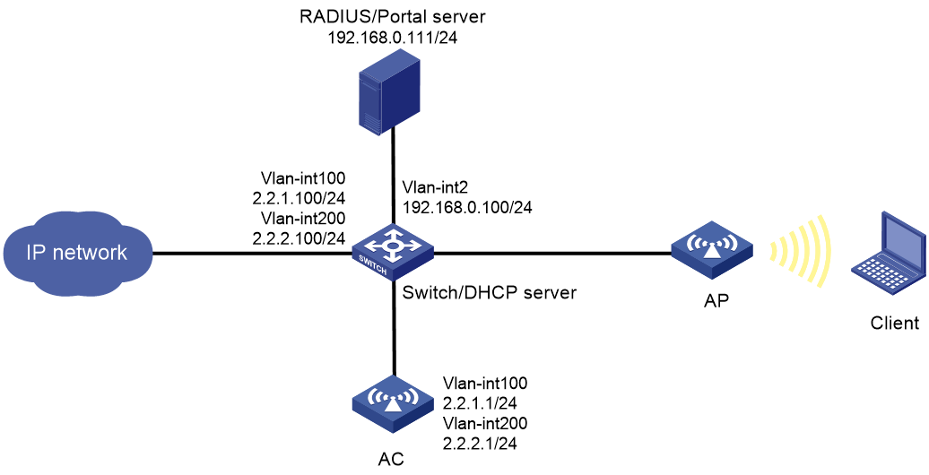
As shown in Figure 1:
· The switch acts as a DHCP server to assign IP addresses to the AP and the client.
· Establish the CAPWAP tunnels between the AC and the AP in VLAN 100.
· Connect the client to the WLAN network in VLAN 200.
· Use IMC as the portal authentication server, portal Web server, and RADIUS server.
Configure the network to meet the following requirements:
· Direct portal authentication is used for wireless clients.
· Before passing portal authentication, the client can access only the portal Web server. After passing the authentication, the client can access other network resources.
· The AP forwards the data traffic from the client directly.
· The client can access network resources through any Layer 2 ports in its access VLAN without re-authentication.
· The IMC server dynamically changes the authorization for the client or forces the client offline.
Analysis
· To allow an authenticated user to access network resources on any Layer 2 ports in its access VLAN without re-authentication, you must enable the portal roaming feature.
· In a local-forwarding WLAN, the AC does not keep ARP entries for portal clients. To ensure that valid users can perform portal authentication, you must enable wireless client validity check on the AC.
· To avoid possible authentication failure caused by frequent logins and logouts of portal clients in a short time, disable the Rule ARP entry feature.
· For the RADIUS server to dynamically change client authorization or force clients offline, you must enable the RADIUS session-control feature on the AC.
· To have the AP forward client data traffic in VLAN 200 on GigabitEthernet 1/0/1, edit a .txt configuration file to add the port to VLAN 200 and upload the file to the AC.
Restrictions and guidelines
· Use the serial ID labeled on the AP's rear panel to specify an AP.
· The portal authentication server type and portal Web server type configured on the AC must be the same as the types of the servers actually used. In this example, the server type is CMCC.
· By default, the portal Web server URL redirected to users does not carry any parameters. You can configure the parameters to be carried in the redirection URL as needed.
· Make sure the fit APs deployed on the network are compatible with the anchor AP (the AC in this document).
Procedures
Configuring the switch
# Create VLAN 100 to transport the traffic in the CAPWAP tunnels between the AC and the AP.
<Switch> system-view
[Switch] vlan 100
[Switch-vlan100] quit
# Create VLAN 200 to transport radio packets for the client.
[Switch] vlan 200
[Switch-vlan200] quit
# Create VLAN 2 for establishing connectivity to the IMC server.
[Switch] vlan 2
[Switch-vlan2] quit
# Assign the interface connected to the RADIUS server to VLAN 2. (Details not shown.)
# Configure GigabitEthernet 1/0/1 (the port connected to the AC) as a trunk port and assign it to VLAN 100 and VLAN 200.
[Switch] interface gigabitethernet 1/0/1
[Switch-GigabitEthernet1/0/1] port link-type trunk
[Switch-GigabitEthernet1/0/1] port trunk permit vlan 100 200
[Switch-GigabitEthernet1/0/1] quit
# Configure GigabitEthernet 1/0/2 (the port connected to the AP) as a trunk port, assign it to VLANs 100 and 200, and set its PVID to VLAN 100.
[Switch] interface gigabitethernet 1/0/2
[Switch-GigabitEthernet1/0/2] port link-type trunk
[Switch-GigabitEthernet1/0/2] port trunk permit vlan 100 200
[Switch-GigabitEthernet1/0/2] port trunk pvid vlan 100
# Enable PoE.
[Switch-GigabitEthernet1/0/2] poe enable
[Switch-GigabitEthernet1/0/2] quit
# Create VLAN-interface 100 and assign an IP address to it.
[Switch] interface vlan-interface 100
[Switch-Vlan-interface100] ip address 2.2.1.100 255.255.255.0
[Switch-Vlan-interface100] quit
# Create VLAN-interface 200 and assign an IP address to it.
[Switch] interface vlan-interface 200
[Switch-Vlan-interface200] ip address 2.2.2.100 255.255.255.0
[Switch-Vlan-interface200] quit
# Create VLAN-interface 2 and assign an IP address to it.
[Switch] interface vlan-interface 2
[Switch-Vlan-interface2] ip address 192.168.0.100 255.255.255.0
[Switch-Vlan-interface2] quit
# Configure DHCP address pool 100 to assign IP addresses to APs. Specify 2.2.1.100 as a gateway address in the address pool.
[Switch] dhcp server ip-pool 100
[Switch-dhcp-pool-100] network 2.2.1.0 mask 255.255.255.0
[Switch-dhcp-pool-100] gateway-list 2.2.1.100
[Switch-dhcp-pool-100] forbidden-ip 2.2.1.1
[Switch-dhcp-pool-100] quit
# Configure DHCP address pool 200 to assign IP addresses to clients. In this example, the DNS server address is the same as the gateway address in the address pool. You must replace it with the actual address of the DNS server on your network.
[Switch] dhcp server ip-pool 200
[Switch-dhcp-pool-200] network 2.2.2.0 mask 255.255.255.0
[Switch-dhcp-pool-200] gateway-list 2.2.2.100
[Switch-dhcp-pool-200] dns-list 2.2.2.100
[Switch-dhcp-pool-200] forbidden-ip 2.2.2.1
[Switch-dhcp-pool-200] quit
# Enable DHCP.
[Switch] dhcp enable
# Configure the interface connected to the external network and the default route. (Details not shown.)
Editing the AP configuration file
# Use a text editor to edit the APs' configuration file, and then upload the file to the central AC. In this example, the configuration file name is map.txt. The following is the AP configuration for this example:
System-view
vlan 200
interface gigabitethernet1/0/1
port link-type trunk
port trunk permit vlan 200
Configuring the anchor AP in AC mode
Configuring interfaces on the AC
# Create VLAN 100 and VLAN-interface 100, and assign an IP address to the VLAN interface. The AC will use this IP address to establish CAPWAP tunnels with the AP.
<AC> system-view
[AC] vlan 100
[AC-vlan100] quit
[AC] interface vlan-interface 100
[AC-Vlan-interface100] ip address 2.2.1.1 24
[AC-Vlan-interface100] quit
# Create VLAN 200 and VLAN-interface 200, and assign an IP address to the VLAN interface. The client will be assigned to this VLAN.
[AC] vlan 200
[AC-vlan200] quit
[AC] interface vlan-interface 200
[AC-Vlan-interface200] ip address 2.2.2.1 24
[AC-Vlan-interface200] quit
# Configure GigabitEthernet 1/0/1 (the port connected to the switch) as a trunk port and assign it to VLANs 100 and 200.
[AC] interface gigabitethernet 1/0/1
[AC-GigabitEthernet1/0/1] port link-type trunk
[AC-GigabitEthernet1/0/1] port trunk permit vlan 100 200
[AC-GigabitEthernet1/0/1] quit
Configuring static routing
# Configure a static route to IMC (the RADIUS servers).
[AC] ip route-static 192.168.0.0 255.255.255.0 2.2.2.100
Configuring a service template
# Create service template st1 and enter its view.
[AC] wlan service-template st1
# Specify the SSID of the service template to service.
[AC-wlan-st-st1] ssid service
# Specify VLAN 200 to the matching clients.
[AC-wlan-st-st1] vlan 200
# Set the AKM mode to PSK, and configure simple character string of 12345678 as the PSK.
[AC-wlan-st-st1] akm mode psk
[AC-wlan-st-st1] preshared-key pass-phrase simple 12345678
# Set the cipher suite to CCMP and set the security IE to RSN.
[AC-wlan-st-st1] cipher-suite ccmp
[AC-wlan-st-st1] security-ie rsn
# Configure the AP as the client data traffic forwarder.
[AC–wlan-st-st1] client forwarding-location ap
[AC-wlan-st-st1] quit
# Create an AP named office and specify its AP model and serial ID. In this example, the AP model is WA6638 and its serial ID is 219801A24F8198E00042.
[AC] wlan ap office model WA6638
[AC-wlan-ap-office] serial-id 219801A24F8198E00042
# Deploy the map.txt configuration file to the AP.
[AC-wlan-ap-office] map-configuration map.txt
# Enter the view of radio 2.
[AC-wlan-ap-office] radio 2
# Bind service template st1 to radio 2, and then enable the radio.
[AC-wlan-ap-office-radio-2] service-template st1
[AC-wlan-ap-office-radio-2] radio enable
[AC-wlan-ap-office-radio-2] quit
[AC-wlan-ap-office] quit
Configuring a RADIUS scheme
# Create a RADIUS scheme named RADIUS scheme rs1 and enter its view.
[AC] radius scheme rs1
# Specify the IP addresses of the primary authentication and accounting RADIUS servers.
[AC-radius-rs1] primary authentication 192.168.0.111
[AC-radius-rs1] primary accounting 192.168.0.111
# Set the shared key to radius in plain text for secure communication with the servers.
[AC-radius-rs1] key authentication simple radius
[AC-radius-rs1] key accounting simple radius
# Configure the AC to remove the ISP domain name from the usernames sent to the RADIUS servers, and specify IP address 2.2.2.1 as the source IP address of outgoing RADIUS packets.
[AC-radius-rs1] user-name-format without-domain
[AC-radius-rs1] nas-ip 2.2.2.1
[AC-radius-rs1] quit
# Enable the RADIUS session-control feature.
[AC] radius session-control enable
# Enable the RADIUS DAS feature and enter RADIUS DAS view.
[AC] radius dynamic-author server
# Specify the RADIUS server at 192.168.0.111 as a DAC and set the shared key to radius in plain text for validating DAE packets from the RADIUS server.
[AC-radius-da-server] client ip 192.168.0.111 key simple radius
Configuring the authentication domain
# Create an ISP domain named dm1 and enter its view.
[AC] domain dm1
# Configure the domain to use RADIUS scheme rs1 for authentication, authorization, and accounting.
[AC-isp-dm1] authentication portal radius-scheme rs1
[AC-isp-dm1] authorization portal radius-scheme rs1
[AC-isp-dm1] accounting portal radius-scheme rs1
# Configure the idle-cut feature to disconnect idle users in the domain. Users are considered idle if they fail to generate a minimum amount of traffic over a period set by the idle-cut timer. In this example, set the idle-cut timer to 15 minutes and the minimum traffic to 1024 bytes.
[AC-isp-dm1] authorization-attribute idle-cut 15 1024
[AC-isp-dm1] quit
Configuring portal authentication
# Create portal authentication server newpt, specify the server IP address as 192.168.0.111, and set the destination UDP port number to 50100 for the AC to send unsolicited portal packets to the portal authentication server.
[AC] portal server newpt
[AC-portal-server-newpt] ip 192.168.0.111 key simple radius
[AC-portal-server-newpt] port 50100
# Specify the server type as CMCC.
[AC-portal-server-newpt] server-type cmcc
[AC-portal-server-newpt] quit
# Configure the URL for portal Web server newpt as http://192.168.0.111:8080/portal.
[AC] portal web-server newpt
[AC-portal-websvr-newpt] url http://192.168.0.111:8080/portal
# Configure the portal redirection URL to carry the ssid, wlanuserip, and wlanacname parameters, and their values are the AP's SSID, the user's IP address, and the AC's name (required by a CMCC portal Web server).
[AC-portal-websvr-newpt] url-parameter ssid ssid
[AC-portal-websvr-newpt] url-parameter wlanuserip source-address
[AC-portal-websvr-newpt] url-parameter wlanacname value AC
# Specify the server type as CMCC for portal Web server newpt.
[AC-portal-websvr-newpt] server-type cmcc
[AC-portal-websvr-newpt] quit
# Configure an IPv4-based portal-free rule to permit portal Web server traffic.
[AC] portal free-rule 0 destination ip 192.168.0.111 24
# Configure IPv4-based portal-free rules to permit DNS server traffic.
[AC] portal free-rule 1 destination ip any udp 53
[AC] portal free-rule 2 destination ip any tcp 53
# Enable intra-VLAN roaming for portal users.
[AC] portal roaming enable
# Disable the Rule ARP entry feature for portal clients.
[AC] undo portal refresh arp enable
# Enable validity check on wireless portal clients.
[AC] portal host-check enable
# Enable direct IPv4 portal authentication for service template st1.
[AC] wlan service-template st1
[AC-wlan-st-st1] portal enable method direct
# Configure the authentication domain for IPv4 portal users as dm1 on service template st1.
[AC-wlan-st-st1] portal domain dm1
# Specify portal Web server newpt on service template st1 for portal authentication.
[AC-wlan-st-st1] portal apply web-server newpt
# Configure the BAS-IP as 2.2.2.1 for portal packets sent from service template st1 to the portal authentication server.
[AC-wlan-st-st1] portal bas-ip 2.2.2.1
# Enable the service template.
[AC–wlan-st-st1] service-template enable
[AC-wlan-st-st1] quit
Configuring the IMC server
This example uses IMC as the RADIUS server and portal server, which runs PLAT 7.1(E0303p13), IMC EIA 7.1(F0302p08), and EIP 7.1(F0302p08).
Configuring the RADIUS server
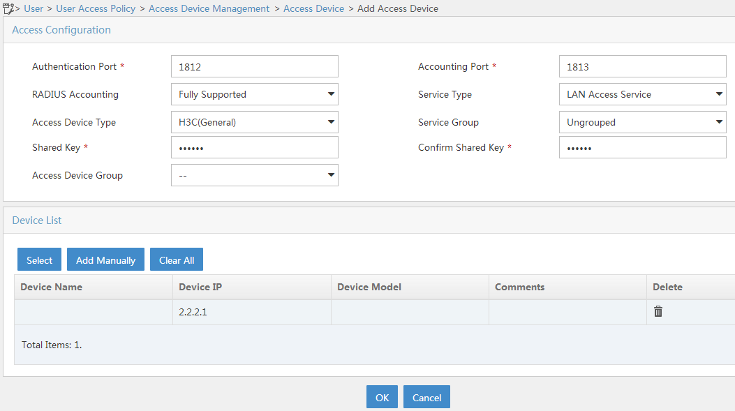
1. Add the AC to IMC as an access device:
a. Log in to IMC and click the User tab.
b. From the navigation pane, select User Access Policy > Access Device Management > Access Device.
c. Click Add.
The Add Access Device page opens.
d. In the Access Configuration area, configure the following parameters:
- Enter radius in the Shared Key and Confirm Shared Key fields. Make sure the key is the same as the key configured on the AC.
- Use the default values for other parameters.
e. In the Device List area, click Select or Add Manually to add the AC at 2.2.2.1 as an access device.
f. Click OK.
Figure 2 Adding the AC to IMC as an access device
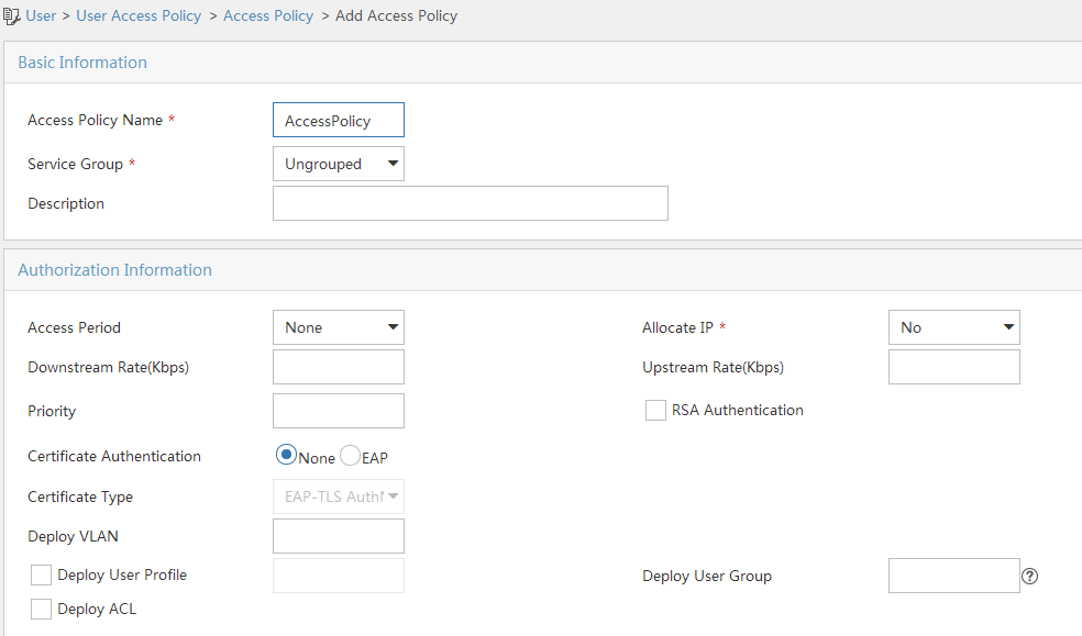
2. Add an access policy.
a. Click the User tab.
b. From the navigation pane, select User Access Policy > Access Policy.
c. Click Add.
d. Enter the access policy name. In this example, the name is AccessPolicy.
e. Select a service group. In this example, the group is Ungrouped.
f. Use the default settings for other parameters.
Figure 3 Adding an access policy
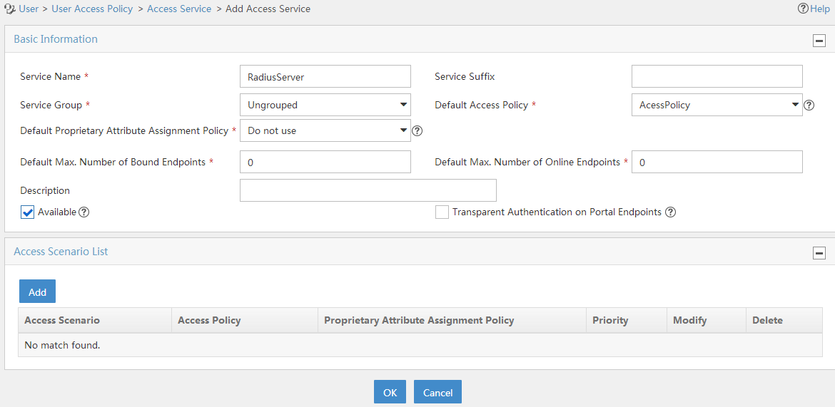
3. Add an access service.
a. Click the User tab.
b. From the navigation pane, select User Access Policy > Access Service.
c. Click Add.
d. Enter the service name. In this example, the service name is RadiusServer.
e. Select AccessPolicy.
f. Use the default settings for other parameters.
g. Click OK.
Figure 4 Adding an access service
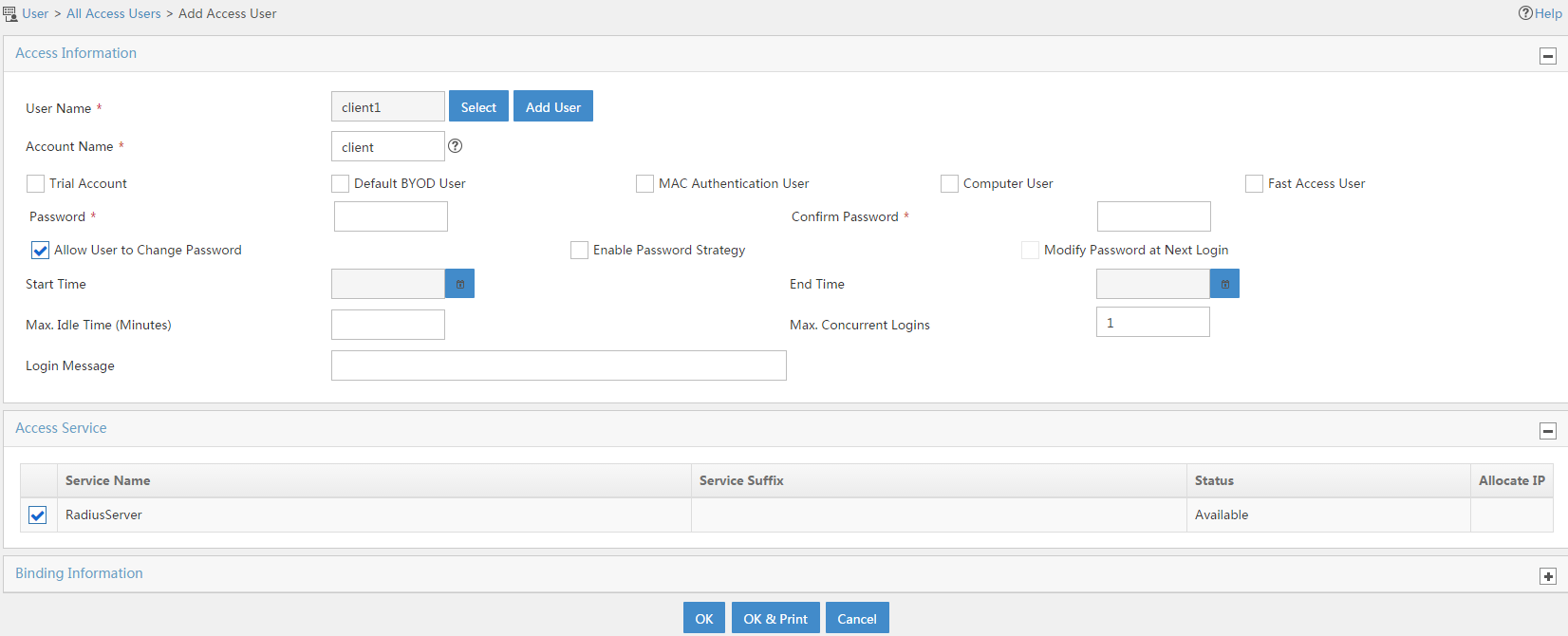
4. Add an access user.
b. From the navigation pane, select Access User > All Access Users.
c. Click Add.
d. Select an existing access user or click Add User to add a new access user.
e. Specify the account name. In this example, the name is client.
f. Set the password.
g. Select service RadiusServer.
h. Use the default settings for other parameters.
i. Click OK.
Figure 5 Adding an access user
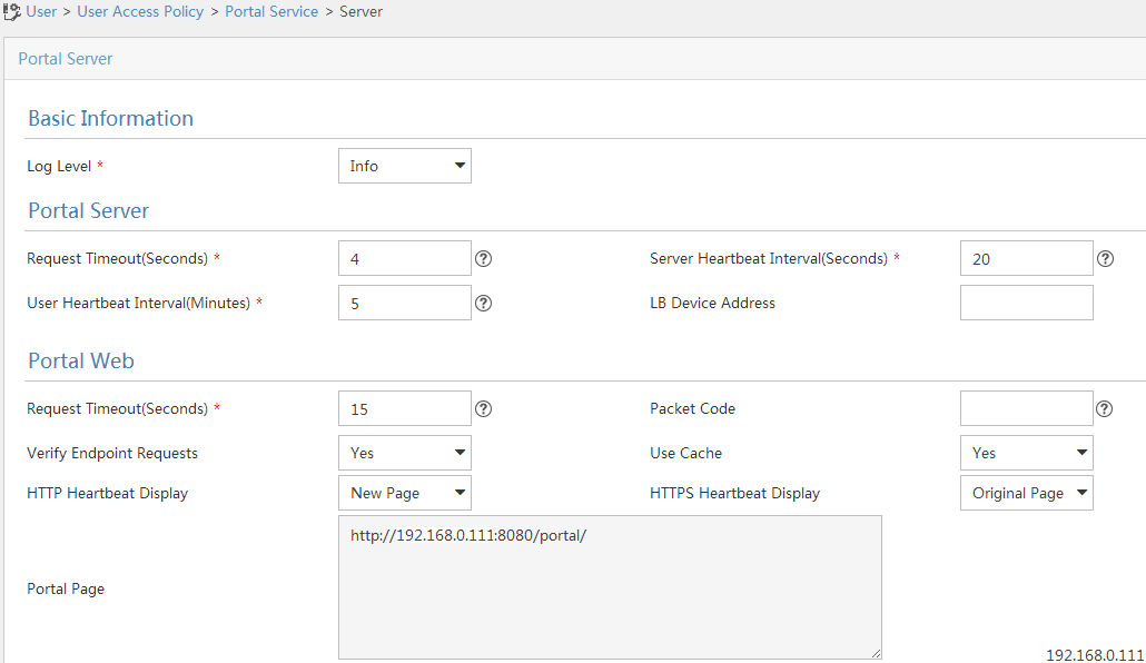
Configuring the portal server
1. Configure portal authentication:
a. Click the User tab.
b. Select User Access Policy > Portal Service > Server from the navigation tree to open the portal server configuration page.
c. Configure the portal server parameters as needed.
This example uses the default settings.
d. Click OK.
Figure 6 Portal authentication server configuration
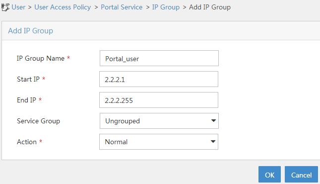
2. Configure the IP address group:
a. Select User Access Policy > Portal Service > IP Group from the navigation tree to open the portal IP address group configuration page.
b. Click Add to open the page as shown in Figure 7.
c. Enter the IP group name. In this example, the name is Portal_user.
d. Enter the start IP address and end IP address of the IP group.
Make sure the client IP address is in the IP group.
e. Select a service group.
This example uses the default group Ungrouped.
f. Select Normal from the Action list.
g. Click OK.
Figure 7 Adding an IP address group
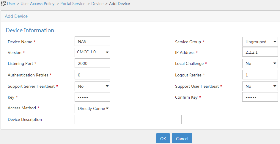
3. Add the AC as a portal device:
a. Select User Access Policy > Portal Service > Device from the navigation tree to open the portal device configuration page.
b. Click Add to open the page as shown in Figure 8.
c. Enter the device name.
d. Specify the version as CMCC 1.0.
e. Enter the IP address of the AC's interface connected to the client.
f. Set whether to support the portal server heartbeat and user heartbeat functions.
In this example, select No for both Support Server Heartbeat and Support User Heartbeat.
g. Enter the key, which must be the same as that configured on the AC.
h. Select Directly Connected from the Access Method list.
i. Use the default settings for other parameters.
j. Click OK.
Figure 8 Adding a portal device
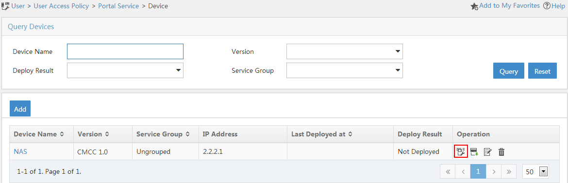
4. Associate the AC with the IP address group:
a. As shown in Figure 9,
click the Port Group Information Management icon ![]() for the device to
open the port group configuration page.
for the device to
open the port group configuration page.
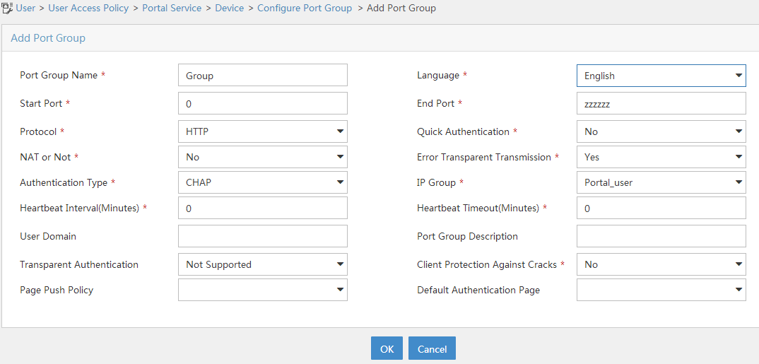
b. Click Add to open the page as shown in Figure 10.
c. Enter the port group name. In this example, the name is Group.
d. Select the configured IP address group.
The IP address used by the user to access the network must be within this IP address group.
e. Use the default settings for other parameters.
f. Click OK.
5. From the navigation pane, select User Access Policy > Service Parameters > Validate System Configuration to commit the configuration changes.
Verifying the configuration
# Verify that all Web requests are redirected to the portal authentication page (http://192.168.0.111:8080/portal) before you pass portal authentication, and you can access Internet resources after being authenticated.
# Execute the display portal user all command on the AC to view online portal user information.
[AC] display portal user all
Total portal users: 1
Username: Client
AP name: office
Radio ID: 2
SSID: service
Portal server: newpt
State: Online
VPN instance: N/A
MAC IP VLAN Interface
0021-6330-0933 2.2.2.2 200 WLAN-BSS1/0/2
Authorization information:
DHCP IP pool: N/A
User profile: N/A
Session group profile: N/A
ACL number: N/A
Inbound CAR: N/A
Outbound CAR: N/A
Web URL: N/A
Configuration files
· AC (anchor AP):
#
vlan 100
#
vlan 200
#
wlan service-template st1
ssid service
vlan 200
akm mode psk
preshared-key pass-phrase cipher $c$3$cMOqsKWekOExvNKyRX/31VXEXHb+gSgn3D2S
cipher-suite ccmp
security-ie rsn
portal enable method direct
portal domain dm1
portal bas-ip 2.2.2.1
portal apply web-server newpt
service-template enable
#
interface Vlan-interface100
ip address 2.2.1.1 255.255.255.0
#
interface Vlan-interface200
ip address 2.2.2.1 255.255.255.0
#
interface GigabitEthernet1/0/1
port link-type trunk
port trunk permit vlan 1 100 200
#
ip route-static 192.168.0.0 24 2.2.2.100
#
radius session-control enable
#
radius scheme rs1
primary authentication 192.168.0.111
primary accounting 192.168.0.111
key authentication cipher $c$3$Sqgqz7lDs4XPnethmAgyAKVlke7qwEkYbQ==
key accounting cipher $c$3$4J/JBRGwqB4F213furJMkB6JWYXBFjWE6g==
user-name-format without-domain
nas-ip 2.2.2.1
#
radius dynamic-author server
client ip 192.168.0.111 key cipher $c$3$AkTEB7OgMYnCqsfDeplhoAgXUek/rVrLZw==
#
domain dm1
authorization-attribute idle-cut 15 1024
authentication portal radius-scheme rs1
authorization portal radius-scheme rs1
accounting portal radius-scheme rs1
#
portal host-check enable
portal free-rule 0 destination ip 192.168.0.0 255.255.255.0
portal free-rule 1 destination ip any udp 53
portal free-rule 2 destination ip any tcp 53
#
portal roaming enable
undo portal refresh arp enable
#
portal web-server newpt
url http://192.168.0.111:8080/portal
server-type cmcc
url-parameter ssid ssid
url-parameter wlanacname value AC
url-parameter wlanuserip source-address
#
portal server newpt
ip 192.168.0.111 key cipher $c$3$AkTEB7OgMYnCqsfDeplhoAgXUek/rVrLZw==
server-type cmcc
#
wlan ap office model WA6638
serial-id 219801A24F8198E00042
map-configuration flash:/map.txt
radio 1
radio 2
radio enable
service-template st1
#
· Switch:
#
dhcp enable
#
vlan 2
#
vlan 100
#
vlan 200
#
dhcp server ip-pool 100
gateway-list 2.2.1.100
network 2.2.1.0 mask 255.255.255.0
forbidden-ip 2.2.1.1
#
dhcp server ip-pool 200
gateway-list 2.2.2.100
network 2.2.2.0 mask 255.255.255.0
dns-list 2.2.2.100
forbidden-ip 2.2.2.1
#
interface Vlan-interface2
ip address 192.168.0.100 255.255.255.0
#
interface Vlan-interface100
ip address 2.2.1.100 255.255.255.0
#
interface Vlan-interface200
ip address 2.2.2.100 255.255.255.0
#
interface GigabitEthernet1/0/1
port link-type trunk
port trunk permit vlan 1 100 200
#
interface GigabitEthernet1/0/2
port link-type trunk
port trunk permit vlan 1 100 200
port trunk pvid vlan 100
poe enable
#
Related documentation
· User Access and Authentication Command Reference in H3C Access Points Anchor AC Mode Command References
· User Access and Authentication Configuration Guide in H3C Access Points Anchor AC Mode Configuration Guides
· WLAN Access Command Reference in H3C Access Points Anchor AC Mode Command References
· WLAN Access Configuration Guide in H3C Access Points Anchor AC Mode Configuration Guides