- Table of Contents
-
- H3C Anchor Access Points in AC Mode Configuration Examples-6W100
- 00-Preface
- 01-H3C Anchor AC Mode Local Forwarding Configuration Examples
- 02-H3C Anchor AC Mode Dual-Link Backup Configuration Examples
- 03-H3C Anchor AC Mode Internal-to-External Access Through NAT Configuration Examples
- 04-H3C Anchor AC Mode Remote Portal Auth in Local Forwarding Configuration Examples
- 05-H3C Anchor AC Mode Remote Portal Auth in Centralized Forwarding Configuration Examples
- 06-H3C Anchor AC Mode Remote 802.1X Auth in Local Forwarding Configuration Examples
- 07-H3C Anchor AC Mode Remote 802.1X Auth in Centralized Forwarding Configuration Examples
- 08-H3C Anchor AC Mode Remote AP Configuration Examples
- Related Documents
-
| Title | Size | Download |
|---|---|---|
| 03-H3C Anchor AC Mode Internal-to-External Access Through NAT Configuration Examples | 79.07 KB |
|
|
|
H3C Anchor Access Points in AC Mode |
|
Internal-to-External Access Through NAT |
|
Configuration Examples |
Copyright © 2022 New H3C Technologies Co., Ltd. All rights reserved.
No part of this manual may be reproduced or transmitted in any form or by any means without prior written consent of New H3C Technologies Co., Ltd.
Except for the trademarks of New H3C Technologies Co., Ltd., any trademarks that may be mentioned in this document are the property of their respective owners.
The information in this document is subject to change without notice.
Introduction
The following information provides examples for configuring NAT to allow internal users to access the external network.
Prerequisites
This document applies to Comware 7-based access controllers and access points. Procedures and information in the examples might be slightly different depending on the software or hardware version of the access controllers and access points.
The configuration examples in this document were created and verified in a lab environment, and all the devices were started with the factory default configuration. When you are working on a live network, make sure you understand the potential impact of every command on your network.
This document assumes that you have basic knowledge of NAT and WLAN.
Example: Configuring NAT to allow internal users to access the external network
The AC in this example is an anchor AP that operates as an AC.
Network configuration
As shown in Figure 1, the AP and the clients obtain IP addresses through DHCP. Configure dynamic NAT on the AC's interface that connects to the external network to allow only the clients at the 192.168.1.0/24 to access the Internet.
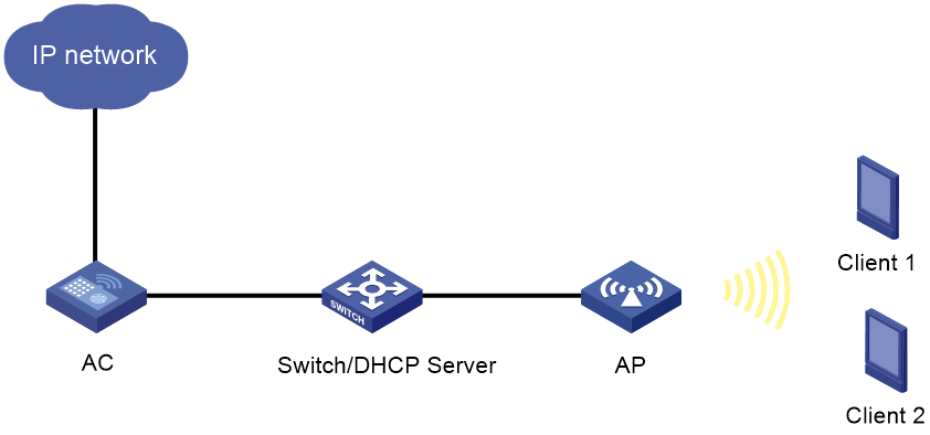
Table 1 Interface and IP address assignment
|
Device |
Interface |
IP address |
Device |
Interface |
IP address |
|
AC |
Vlan-int100 |
192.168.0.1/24 |
Switch |
Vlan-int100 |
192.168.0.2/24 |
|
|
Vlan-int200 |
192.168.1.1/24 |
|
Vlan-int200 |
192.168.1.2/24 |
|
|
Vlan-int300 |
202.38.1.1/24 |
|
|
|
Restrictions and guidelines
When you configure NAT to allow internal users to access the external network, follow these restrictions and guidelines:
· If you configure NAT on VLAN interfaces, use the address group as a best practice for dynamic NAT.
· Do not add the public IP address of the VLAN interface to the NAT address group.
· If the AC uses only one public IP address of the VLAN interface for dynamic NAT, use the port-range command to specify a proper port range. As a best practice, use the port range from 10000 to 65535 to ensure that the service ports on the AC are not used by NAT.
· Make sure the devices can reach each other. In this example, the routing configuration is not shown.
Procedures
Configuring the AC
Configuring the interfaces on the AC
# Create VLAN 100 and configure VLAN-interface 100. The AC will use this IP address to establish a CAPWAP tunnel with the AP.
<AC> system-view
[AC] vlan 100
[AC-vlan100] quit
[AC] interface vlan-interface 100
[AC-Vlan-interface100] ip address 192.168.0.1 24
[AC-Vlan-interface100] quit
# Create VLAN 200 and configure VLAN-interface 200. The clients will access the WLAN network through this VLAN.
[AC] vlan 200
[AC-vlan200] quit
[AC] interface vlan-interface 200
[AC-Vlan-interface200] ip address 192.168.1.1 24
[AC-Vlan-interface200] quit
# Create VLAN 300 and configure VLAN-interface 300. The AC will use this VLAN for dynamic address translation.
[AC] vlan 300
[AC-vlan300] quit
[AC] interface vlan-interface 300
[AC-Vlan-interface300] ip address 202.38.1.1 24
[AC-Vlan-interface300] quit
# Configure XGE 1/0/1 on the AC that connects the AC to the switch, as a trunk port, and assign it to VLAN 100 and VLAN 200.
[AC] interface Ten-GigabitEthernet 1/0/1
[AC-Ten-GigabitEthernet1/0/1] port link-type trunk
[AC-Ten-GigabitEthernet1/0/1] port trunk permit vlan 100 200
[AC-Ten-GigabitEthernet1/0/1] quit
Configuring WLAN services
# Create service template 1 and enter its view.
[AC] wlan service-template 1
# Set the SSID to service.
[AC-wlan-st-1] ssid service
# Assign clients coming online through service template service to VLAN 200.
[AC-wlan-st-1] vlan 200
# Configure the AC to forward client data traffic.
[AC-wlan-st-1] client forwarding-location ac
# Set the authentication and key management mode to PSK, and configure simple string 12345678 as the PSK.
[AC-wlan-st-1] akm mode psk
[AC-wlan-st-1] preshared-key pass-phrase simple 12345678
# Set the CCMP cipher suite and enable the RSN IE in the beacon and probe responses.
[AC-wlan-st-1] cipher-suite ccmp
[AC-wlan-st-1] security-ie rsn
# Enable the service template.
[AC-wlan-st-1] service-template enable
[AC-wlan-st-1] quit
# Create AP 6630x with model WA6630X-JP, and set the serial ID to 210235A1GQC152001076.
[AC] wlan ap 6630x model WA6630X-JP
[AC-wlan-ap-6630x] serial-id 210235A1GQC152001076
# Enter radio view.
[AC-wlan-ap-6630x] radio 2
# Bind service template 1 to radio 2, and enable the radio.
[AC-wlan-ap-6630x-radio-2] service-template 1
[AC-wlan-ap-6630x-radio-2] radio enable
[AC-wlan-ap-6630x-radio-2] quit
[AC-wlan-ap-6630x] quit
Configuring dynamic NAT
# Configure address group 0. Add two public IP addresses 202.38.1.2 and 202.38.1.3 to the address group.
[AC] nat address-group 0
[AC-address-group-0] address 202.38.1.2 202.38.1.3
[AC-address-group-0] quit
# Configure ACL 2000 to identify packets sourced from 192.168.1.0/24.
[AC] acl basic 2000
[AC-acl-ipv4-basic-2000] rule permit source 192.168.1.0 0.0.0.255
[AC-acl-ipv4-basic-2000] quit
# Configure a default route to change the VLAN to which the packets belong from VLAN 200 to VLAN 300.
[AC] ip route-static 0.0.0.0 0.0.0.0 Vlan-interface 300
# Configure outbound dynamic IP and port translation on VLAN-interface 300 to translate the source IP address of outgoing packets permitted by ACL 2000 into addresses in address group 0.
[AC] interface vlan-interface 300
[AC-Vlan-interface300] nat outbound 2000 address-group 0
[AC-Vlan-interface300] quit
Configuring the switch
Configuring the interfaces on the switch
# Create VLAN 100, and assign an IP address to VLAN-interface 100. The switch will use this VLAN to forward traffic on the CAPWAP tunnel between the AC and AP.
<Switch> system-view
[Switch] vlan 100
[Switch-vlan100] quit
[Switch] interface vlan-interface 100
[Switch-Vlan-interface100] ip address 192.168.0.2 24
[Switch-Vlan-interface100] quit
# Create VLAN 200, and assign an IP address to VLAN-interface 200. This VLAN is used to forward packets from the clients.
[Switch] vlan 200
[Switch-vlan200] quit
[Switch] interface vlan-interface 200
[Switch-Vlan-interface200] ip address 192.168.1.2 24
[Switch-Vlan-interface200] quit
# Configure GigabitEthernet 1/0/1, the interface that connects to the AC, as a trunk port, and assign it to VLAN 100 and VLAN 200.
[Switch] interface gigabitethernet 1/0/1
[Switch-GigabitEthernet1/0/1] port link-type trunk
[Switch-GigabitEthernet1/0/1] port trunk permit vlan 100 200
[Switch-GigabitEthernet1/0/1] quit
# Configure GigabitEthernet 1/0/2, the interface that connects to the AP, as an access port, and assign it to VLAN 100.
[Switch] interface gigabitethernet 1/0/2
[Switch-GigabitEthernet1/0/2] port link-type access
[Switch-GigabitEthernet1/0/2] port access vlan 100
# Enable PoE.
[Switch-GigabitEthernet1/0/2] poe enable
[Switch-GigabitEthernet1/0/2] quit
Configuring DHCP services
# Enable DHCP.
[Switch] dhcp enable
# Configure DHCP address pool vlan100 to dynamically assign IP addresses on subnet 192.168.0.0/16 to the AP. Specify 192.168.0.1 as the excluded IP address and gateway address.
[Switch] dhcp server ip-pool vlan100
[Switch-dhcp-pool-vlan100] network 192.168.0.0 mask 255.255.0.0
[Switch-dhcp-pool-vlan100] forbidden-ip 192.168.0.1
[Switch-dhcp-pool-vlan100] gateway-list 192.168.0.1
[Switch-dhcp-pool-vlan100] quit
# Configure DHCP address pool vlan200 to dynamically assign IP addresses on subnet 192.168.1.0/24 to the clients. Specify 192.168.1.1 as the gateway address and DNS server address. Configure the DNS server address for clients based on the network plan. In this example, the DNS server address is the same as the gateway address.
[Switch] dhcp server ip-pool vlan200
[Switch-dhcp-pool-vlan200] network 192.168.1.0 mask 255.255.255.0
[Switch-dhcp-pool-vlan200] gateway-list 192.168.1.1
[Switch-dhcp-pool-vlan200] dns-list 192.168.1.1
[Switch-dhcp-pool-vlan200] quit
Verifying the configuration
# Verify that when a user on subnet 192.168.1.0/24 accesses the Internet, dynamic NAT is performed on the packets from the user. Execute the display nat session verbose command to display the NAT session information.
[AC] display nat session verbose
Slot 1:
Initiator:
Source IP/port: 192.168.1.10/1628
Destination IP/port: 202.38.1.100/21
DS-Lite tunnel peer: -
VPN instance/VLAN ID/Inline ID: -/-/-
Protocol: TCP(6)
Inbound interface: Vlan-interface200
Responder:
Source IP/port: 202.38.1.100/21
Destination IP/port: 202.38.1.2/1024
DS-Lite tunnel peer: -
VPN instance/VLAN ID/Inline ID: -/-/-
Protocol: TCP(6)
Inbound interface: Vlan-interface300
State: TCP_ESTABLISHED
Application: FTP
Start time: 2015-11-28 16:54:35 TTL: 2699s
Initiator->Responder: 1 packets 84 bytes
Responder->Initiator: 1 packets 84 bytes
Total sessions found: 1 s
Configuration files
#
vlan 100
#
vlan 200
#
vlan 300
#
wlan service-template 1
ssid service
vlan 200
client forwarding-location ac
akm mode psk
preshared-key pass-phrase simple 12345678
cipher-suite ccmp
security-ie rsn
service-template enable
#
interface Vlan-interface100
ip address 192.168.0.1 255.255.255.0
#
interface Vlan-interface200
ip address 192.168.1.1 255.255.255.0
#
interface Vlan-interface300
ip address 202.38.1.1 255.255.255.0
nat outbound 2000 address-group 0
#
interface Ten-GigabitEthernet1/0/1
port link-type trunk
port trunk permit vlan 100 200
#
ip route-static 0.0.0.0 0.0.0.0 Vlan-interface 300
#
acl basic 2000
rule 0 permit source 192.168.1.0 0.0.0.255
#
nat address-group 0
address 202.38.1.2 202.38.1.3
#
wlan ap 6630x model WA6630X-JP
serial-id 210235A1GQC152001076
radio 1
radio 2
radio enable
service-template 1
#
· Switch:
#
vlan 100
#
vlan 200
#
interface Vlan-interface100
ip address 192.168.0.2 255.255.255.0
#
interface Vlan-interface200
ip address 192.168.1.2 255.255.255.0
#
interface GigabitEthernet1/0/1
port link-type trunk
port trunk permit vlan 1 100 200
#
interface GigabitEthernet1/0/2
port link-type access
port access vlan 100
poe enable
#
dhcp server ip-pool vlan100
gateway-list 192.168.0.1
network 192.168.0.0 mask 255.255.0.0
forbidden-ip 192.168.0.1
#
dhcp server ip-pool vlan200
gateway-list 192.168.1.1
network 192.168.1.0 mask 255.255.255.0
dns-list 192.168.1.1
dhcp enable
Related documentation
· Network Connectivity Command Reference in H3C Access Points Anchor AC Mode Command References
· Network Connectivity Configuration Guide in H3C Access Points Anchor AC Mode Configuration Guides
· WLAN Access Command Reference in H3C Access Points Anchor AC Mode Command References
· WLAN Access Configuration Guide in H3C Access Points Anchor AC Mode Configuration Guides