- Table of Contents
- Related Documents
-
| Title | Size | Download |
|---|---|---|
| 03-H3C Scenario-Based WLAN Design and Deployment Guide | 1.49 MB |
|
|
|
|
|
H3C Scenario-Based |
|
WLAN Design and Deployment Guide |
|
|
|
New H3C Technologies Co., Ltd. http://www.h3c.com
Document version: 6W100-20220830 |
School wireless application scenarios
WLAN coverage analysis for functional areas
Optimization guidelines and best practices
Comprehensive office area scenarios
Optimization guidelines and best practices
802.1X users come online and go offline frequently
Large venue high-density coverage
WLAN coverage analysis for functional areas
Optimization guidelines and best practices
802.1X users come online and go offline frequently
WLAN coverage analysis for functional areas
Optimization guidelines and best practices
Indoor wireless deployment
Overview
|
|
IMPORTANT: For good signal coverage, use the following guidelines for indoor wireless deployment. · Deploy APs with a coverage radius of 20 m (65.62 ft) per AP. · Allow a maximum of 30 concurrent users for each 5G link. · Allow a maximum of 15 concurrent users for each 2.4G link. |
The indoor environment can be divided into the following four categories with respect to the wireless coverage area and number of access clients:
· Small coverage radius and small number of access clients—Such as small meeting rooms, bars, cafes, and households. Scenarios like student dormitories and hospital wards are composed of such individual scenarios.
· Small coverage radius and large number of access clients—Such as open office areas, large ladder classrooms, large and medium-sized conference rooms, large lecture halls, and large venues.
· Large coverage radius and small number of access clients—Such as hotel rooms, banking business outlets, village houses, village yards, and KTV rooms.
· Large coverage radius and large number of access clients—Such as airports, stadiums, railway station waiting halls, and popular scenic spots.
This document describes the WLAN deployment solution for the following scenarios:
· School wireless application scenarios—Include student dormitory and teaching area scenarios.
· Comprehensive office area scenarios—Include open office area, lecture hall, large and medium-sized conference room scenarios.
· Large venue high-density access scenarios—Include large conference hall, stadium, airport, and railway station scenarios.
· Wireless medical scenarios.
School wireless application scenarios
Building wireless campus networks and offering WLAN signal coverage on the campus has become the mainstream trend for education informationization. In a school, student dormitories and teaching areas have different requirements for WLAN signal coverage.
· Student dormitories
¡ Relatively fixed number of users.
¡ High bandwidth requirement.
¡ High proportion of large packets.
¡ Regular Internet access time.
¡ Widely varying types of wireless terminals (such as mobile phones, computers, and PADs).
· Teaching areas, including classrooms, faculty office areas, large ladder classrooms, libraries, stadiums, and other open venues.
¡ High user density.
¡ Large number of concurrent connections.
¡ Large AP co-channel interference.
WLAN coverage analysis for functional areas
In the school scenario, the main functional areas include office buildings, classrooms, student dormitories, libraries, and outdoor areas. These functional areas are different in user density, network usage frequency, building pattern, and bandwidth demand.
· Office buildings
¡ Characteristics
- The users are mainly teachers and postgraduates in the teaching and research section, dispersedly scattered in the building.
- Fixed working hours and network access time.
- Mainly mail and Internet services.
- Large area, thick walls, and with many metal objects such as file cabinets.
¡ WLAN deployment guidelines: Focus on bandwidth guarantee, sufficient number of APs, and appropriate AP Installation positions.
· Classrooms and libraries
¡ Characteristics
- Users are mainly students and teachers.
- Large number of concurrent connections from wireless terminals.
- Obstacles such as walls and bookshelves exist.
¡ WLAN deployment guidelines: Install APs in the room to ensure good signal coverage in the target area.
· Student dormitory
¡ Characteristics
- Users are mainly students.
- Area where most network activities are conducted.
- Increasing consumption activities over the network.
¡ WLAN deployment guidelines: Ensure bandwidth and signal strength.
· Outdoor venues
¡ Characteristics: Increasing users and network activities with the popularity of smart terminals.
¡ WLAN deployment guidelines: Ensure coverage signal strength and improve user access capacity (increasing the number of APs and reducing the outdoor coverage area of a single AP).
WLAN deployment schemes
Student dormitory
The student dormitory is composed of multiple rooms similar in size, pattern, and wall thickness. It is a typical scenario with a small coverage radius and few access terminals. You must consider the number of users in each room and signal attenuation by a single wall in designing the WLAN deployment scheme and make sure the scheme provides not only sufficient coverage and bandwidth and but also economy efficiency. Therefore, in the student dormitory scenario, use Wi-Fi signal coverage as an auxiliary means for network coverage to provide value-added wireless access in addition to wired access.
|
|
NOTE: In the student dormitory, design the WLAN coverage scheme independently for each floor, based on the user demand on the floor. |
Follow these guidelines for designing the WLAN coverage scheme for the student dormitory:
· Ensure effective WLAN signal interaction between APs and wireless terminals, and make sure all signal parameters meet the requirements.
· Provide effective bandwidth and guarantee bandwidth for access users.
· Consider not only the environmental pattern, but also the service features, usage habits, and specific needs of the users, and reflect these characteristics in the design.
Staff office area, ordinary classroom report hall, and large ladder classroom
You can take a staff office area, ordinary classroom report hall, or large ladder classroom as a conventional small and medium-sized indoor coverage scenario to design the WLAN coverage scheme. Based on the coverage area size and the number of access users, install one or more APs in the area as a best practice.
Library and Gymnasium
For open scenes such as libraries and gymnasiums, see H3C Comware 7 High-Density WLAN Deployment Guide for designing the WLAN deployment scheme.
WLAN deployment examples
Classroom
According to the classroom size, you can deploy one or multiple APs for wireless coverage as needed.
· Single AP coverage
The steel-concrete teaching building has thick load-bearing walls, partition walls, and doors that can greatly attenuate WLAN signals. Therefore, install and deploy APs in the classroom as a best practice.
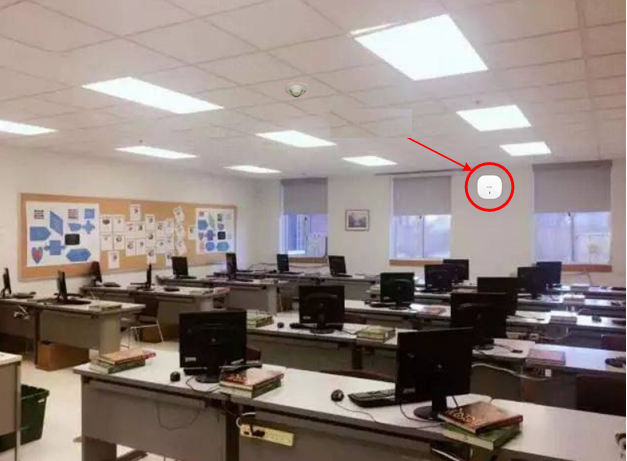
You can install the AP on the wall behind the main podium, or install the AP on the ceiling. Typically, the AP is installed on the wall because most ordinary classrooms do not have ceiling. Wireless signals can penetrate one layer of isolation wall to provide coverage.
A notice board with words such as "Wi-Fi signals in this area" can be installed in key coverage areas such as classrooms, to guide students in need to use the wireless services in this area.
Figure 1 Single AP coverage in a classroom
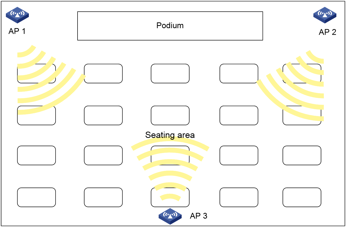
· Multiple AP coverage
In a large ladder classroom, multiple APs are usually installed because there are a large number of concurrent access users. Typically this kind of classroom does not have the components for ceiling-mounting APs. The APs are usually installed on the wall. To avoid co-channel interference, consider channel division between the APs. In addition, keep a certain distance between the AP installation positions.
As shown in Figure 2, install an AP on each side of the podium at the front of the classroom, and the third AP on the wall at the back of the classroom. The following is a channel deployment scheme for your reference:
¡ To use the 2.4G band, specify channel 1, 6, and 11 for AP 1, AP 2, and AP 3, respectively.
¡ To use the 20MHz bandwidth mode on the 5G band, you can specify low frequency and high frequency channels in combination for AP 1, AP 2 and AP 3, for example, channels 149, 153, 157; 36, 48, 149; or 36, 149, 165, respectively.
¡ To use the 40MHz bandwidth mode on the 5G band, specify any three of channels 36/40, 44/48, 149/153, and 157/161 for AP 1, AP 2 and AP 3.
Figure 2 Multiple AP coverage in a classroom
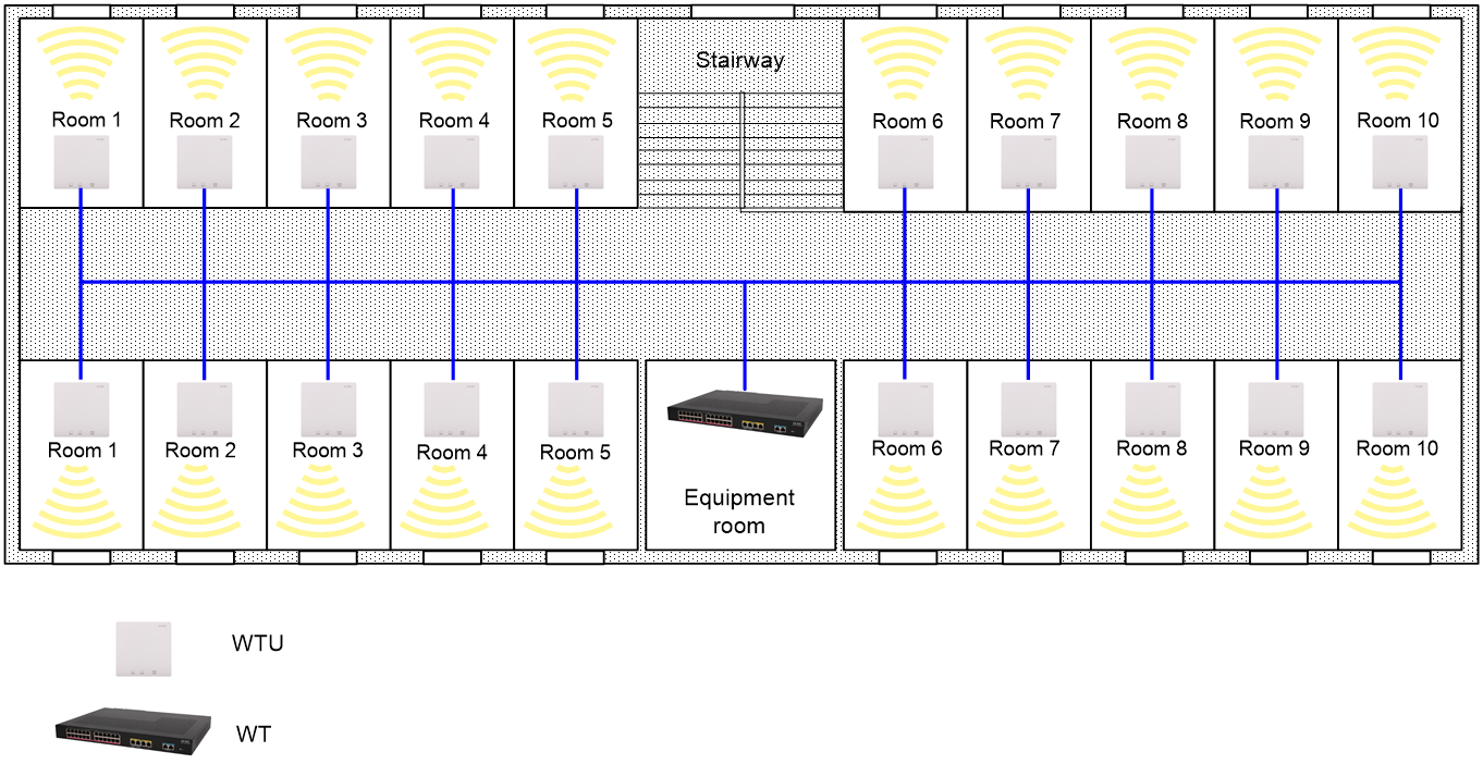
Student dormitory
As a best practice, use the wireless terminator (WT) solution for wireless coverage in the student dormitory.
As shown in Figure 3, when many wireless terminals exist in each room, install a WTU in each room of the dormitory as a best practice to ensure effective bandwidth and better online experience and improve the overall access capacity of the wireless network. Avoid overlapping of adjacent channels of the wireless terminal units (WTUs) and adjust the power appropriately to reduce mutual interference between the WTUs.
Figure 3 WT solution for the student dormitory
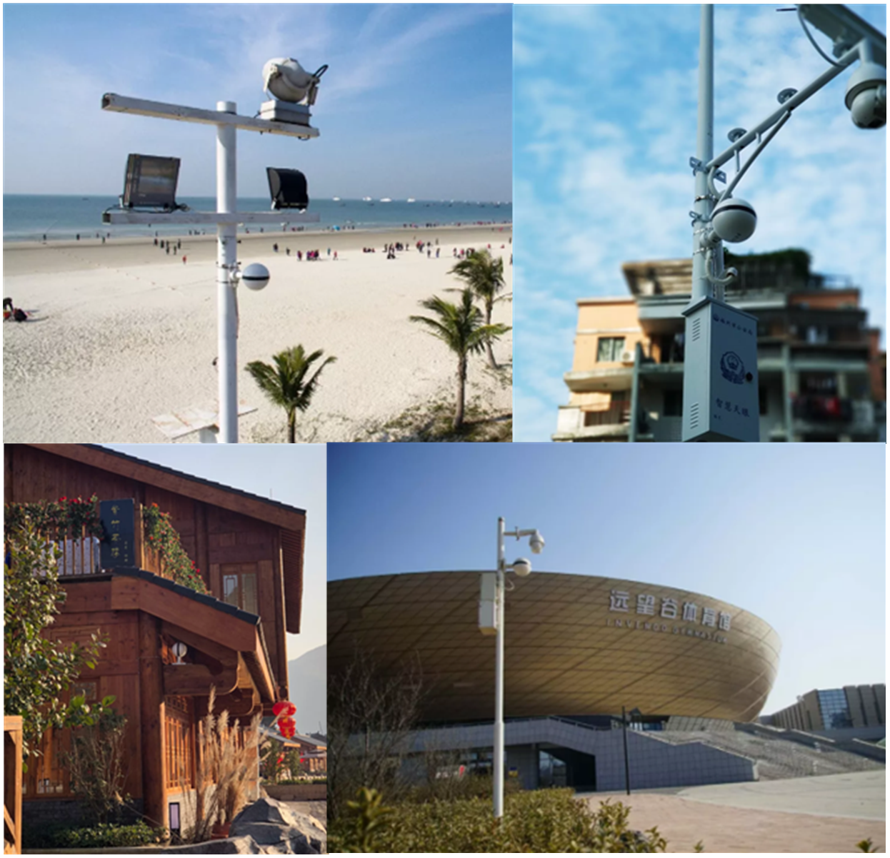
Outdoor venues
Outdoor venues mainly refer to playgrounds, lawns, and student activity areas. There are a small number of users that use small account of traffic in such areas. You must strictly follow outdoor equipment installation guidelines for the deployment and ensure optimal wireless coverage on the venue.
A directional plate antenna with a larger main lobe angle in the vertical direction is usually used for outdoor area coverage on the campus. For installation on the roof and wall, you need to adjust the antenna installation angle (generally downward tilt angle) for optimal coverage. The linear coverage distance in the main lobe direction of the antenna must reach 150 to 300 m (492.13 to 984.26 ft), without obstacles such as trees.
On a site survey for outdoor coverage, fully negotiate with the customer to determine the connection method for the power cords, data cables, and grounding cables, as well as the installation method of poles and lightning protection facilities. The outdoor equipment installation guidelines must be strictly followed to ensure optimal wireless coverage.
|
|
NOTE: For buildings with thick materials difficult for wireless signals to penetrate, you can consider to use outdoor wireless coverage from the opposite building to supplement and improve the wireless coverage near the windowsill of the building. |
Figure 4 Wireless coverage on outdoor venues
Recommended product models
Select APs as described in Table 1 for different WLAN coverage scenarios.
Table 1 Recommended product models for different WLAN coverage scenarios
|
Scenario |
Characteristics |
Recommended products |
WLAN deployment guidelines |
|
Student dormitory |
· Many rooms, regular layout, and thick walls. · Relatively fixed number of wireless terminals in each room. |
Wall jack APs WTUs |
Deploy one wall jack AP for each room or one WTU for every two rooms as required to ensure both bandwidth and signal strength. Avoid deploying APs in the corridor. As a best practice, install APs in the rooms and make full use of wall isolation of wireless signals to reduce mutual interference between APs and improve the overall performance of the wireless network. A WTU can be used only when the wall thickness of the dormitory room does not exceed 25 cm (9.84 in) |
|
Teaching district, staff office area |
· Large area, thick walls, many metal objects such as filing cabinets. · Users are dispersedly scattered in low density. · Mainly mail and Internet services |
Wall jack APs APs |
Ensure bandwidth, sufficient number of APs, and appropriate installation positions. |
|
Ordinary classroom |
· Has obstacles such as walls. · Large number and different types of wireless terminals such as mobile phones, pads, notebooks. · Large wireless access demand. |
APs |
Install the AP indoors to ensure good signal coverage in the target area. |
|
Library, canteen, gymnasium |
Large area and concurrent user accesses. |
Dual- or triple-radio APs |
See the deployment guidelines for office scenario or high-density meeting scenarios. |
|
Outdoor venue |
Increasing number of users. |
Outdoor APs |
Ensure signal coverage and allow high-density user access. You can reduce the outdoor coverage area of a single AP and increase the number of APs. |
Typical networking scheme
The school scenario has the following characteristics in terms of wireless services:
· Wireless services in students' dormitory are mainly used for Web page browsing, video playing, and game playing that are demanding for bandwidth and real-time performance.
· The number of wireless users in the whole network ranges from thousands to tens of thousands.
· A large number of concurrent accesses.
· Regular online time and high requirements for bandwidth.
As a best practice, use the following network scheme in the school scenario:
· Use local forwarding to reduce the workload on the AC. If a centralized forwarding network has been established, enable hardware forwarding mode on the high-end wireless controller to improve wireless traffic forwarding efficiency.
· Configure dual-link backup or IRF dual-device backup for the access controller. The medium and high-end devices, such as WX3500H and later, support AP license sharing.
· Configure strict account-based traffic limiting on the broadband access server (BAS). Enable H3C-proprietary smart flow control and user isolation on the wireless devices as required, and manually limit the number of access users according to the specific scenarios, bandwidth requirements, AP types, to match the actual network conditions.
· Use PSK encryption, 802.1x authentication, or portal authentication as a best practice for wireless user authentication.
· If multiple ACs are deployed, enable transparent portal authentication on ACs for seamless roaming between the ACs. To avoid repeated portal authentications on a terminal roaming between ACs, execute the client vlan-alloc dynamic command to assign the terminal to a VLAN manually to ensure that the VLAN and IP address of the terminal will not be changed.
Optimization guidelines and best practices
To help you select and deploy optimizations on an office WLAN, the optimization guidelines are categorized into the following types depending on their necessity:
· Required—Optimizations that you must deploy and in strict compliance with the requirements and guidelines.
· Strongly recommended—Top optimizations that help you improve network performance and user experience, especially when the WLAN performs poorly or requires high roaming experience. Deploy strongly recommended optimizations unless it has a negative impact on services or the customer requires to not deploy it.
· Recommended—Optimizations that might help you improve network performance and user experience. Deploy a recommended optimization unless it has a negative impact on services or the customer requires to not deploy it. After you deploy a recommended optimization, you must monitor the WLAN to make sure the deployment helps improve WLAN performance.
Increasing signal strength for the target coverage area (required)
Make sure the clients can receive a fair signal in the target coverage area.
The following are the minimum signal strengths for different types of clients:
· Laptops— -70 dBm.
· Smart clients— -65 dBm.
Use either of the following methods to obtain information about received signal strength on a client:
· Use a Wi-Fi network scanner application such as inSSIDer to obtain the accurate signal strength value of a client.
· Use the Wi-Fi icon on the client to determine its signal strength. Make sure the Wi-Fi icon shows three solid bars, which indicate signal strength higher than -70 dBm.
Make sure the client RSSI values are 25 or higher on the APs.
To identify the RSSI value of client signals on APs, execute the display wlan client mac-address mac-address verbose command on their AC, and then examine the RSSI field in the command output.
Using a hexagonal AP placement (required)
Wi-Fi signal propagation in space is three dimensional.
To improve WLAN performance:
1. Do a thorough site survey to identify the space environment.
2. Make an optimal AP placement plan. Take into full account the characteristics of Wi-Fi signal propagation in the particular space to minimize the signal interference between APs on the same channel. To begin with, avoid the leakage of control signal between floors.
Setting the channel plan and the working channels of APs (required)
The coverage areas of APs might overlap in a high-density environment, resulting in signal interference between APs. WLAN performance would be low if all its APs operate on the same channel to share frequency resources.
To avoid adjacent channel interference, assign non-overlapping channels to adjacent APs. For example, use non-overlapping channels 1, 6, and 11 for channel assignment to 2.4 GHz radios on APs.
To avoid CCI on the same floor and between floors, use a hexagonal pattern for vertical and horizontal AP layout.
Make sure CCI is minimized when you manually assign working channels to AP radios.
As a best practice to increase channel isolation and reuse for higher WLAN performance, use 20 MHz or 40 MHz bandwidth mode for 802.11ac radios.
The default bandwidth mode for 802.11ac radios is 80 MHz. To change the bandwidth mode, use the channel band-width command.
Setting the maximum transmit power of APs (required)
Tune AP transmit power on a per virtual WLAN basis.
By default, all APs transmit at the supported maximum transmit power.
To decrease co-channel interference between APs that operate on the same channel and maximize channel reuse, decrease the maximum transmit power of some APs on the same channel as appropriate.
As a best practice, do not enable transmit power control (TPC) to dynamically adapt AP transmit power to the real-time WLAN conditions. A client monitors all available signals for their signal strength. TPC might cause the clients to roam unnecessarily between APs, resulting in degraded user experience.
Using separate VLANs for WLAN services (required)
A WLAN is a Layer 2 network that is typically broadcast and multicast intensive and is directly connected to the wired network.
To prevent the large amount of broadcast and multicast traffic from impacting the wired network, and confine attacks and the spread of viruses, use separate VLANs for WLAN services.
Isolating the clients in a VLAN at Layer 2 (strongly recommended)
All APs in a VLAN receive the broadcast and multicast packets from all clients in that VLAN. Because a client typically sends broadcast and multicast packets at the minimum rate, user experience will decrease as the number of broadcasts increase to occupy radio resources.
Use the following best practices to reduce broadcast and multicast traffic on the WLAN for better performance:
· Configure the AC to disable the clients in the same VLAN to communicate directly with each other and enable all clients to communicate with each other through their respective gateways.
· Use the undo user-isolation permit-broadcast command to disable forwarding broadcast and multicast traffic from wired users to wireless users except the wired users specified by using the user-isolation vlan permit-mac command.
In this situation, the wireless clients can still send broadcast and multicast traffic to wired users.
When you configure intra-VLAN user isolation, use the following guidelines:
· If the network has a VRRP deployment, the permitted MAC list configured by using the user-isolation vlan permit-mac command must include the virtual and real MAC addresses of the VRRP gateway.
· When the APs or wireless terminators (WTs) on the WLAN perform local forwarding, you must issue intra-VLAN user isolation settings to the APs or the WTs.
· Configure the peer ports between the AC and the switches to permit only VLANs required for communication. Avoid using the permit vlan all command to assign the ports to all VLANs.
Port isolation
In order to achieve Layer 2 isolation between ports, you can add different ports to different VLANs, but the VLAN resources are limited. Port isolation allows you to add ports to the isolation group for Layer 2 isolation, to save VLAN resources.
Disabling low rates (strongly recommended)
Each WLAN standard supports a set of data rates. For example, 802.11g supports 1, 2, 5.5, 11, 6, 9, 12, 18, 24, 36, 48, and 54 Mbps. Typically, wireless devices (for example, clients and APs) send frames at a rate dynamically selected from the rate set supported on the WLAN. When sending broadcasts and management frames, they typically use the lowest data rate (1 Mbps). This mechanism causes inefficient use of radio resources and degraded user experience when a large amount of broadcast traffic is present.
To improve radio use efficiency for better experience:
· Disable low data rates 1, 2, 5.5, 6, and 9 Mbps in a typical indoor deployment.
Most indoor deployments provide a good signal to clients in the coverage area. Disabling low data rates are unlikely to cause packet drops that might occur because the received signal of clients is weak or the clients is far away from the APs.
· If some of the clients cannot associate with an AP even though they can detect the signal from that AP, restore the default transmission rate setting on the AP radio.
For example, an 802.11b radio supports 5.5 Mbps and 11Mbps by default. If disabling these two rates might prevent some clients from associating to the AP, restore the default transmission rate setting.
Rate-limiting clients (strongly recommended)
The bandwidth of an AP is shared among its associated clients. To prevent aggressive use of bandwidth by some clients from affecting other clients, set a rate limit on clients.
The wireless clients in the dormitory area of the school scenario have high bandwidth requirements and the online time is relatively concentrated. To prevent downloads of a single client from affecting the services of other clients. Use the client-rate-limit command to enable rate limiting on wireless clients.
When you configure client rate limiting, use the following guidelines:
· Use client rate limiting or intelligent bandwidth guarantee, but not both.
· You can configure a client rate limit both on a radio and in the service template bound to that radio. In this situation, the lower value between the two limit settings applies to the template-matching clients on that radio.
Downlink port isolation on wall jack APs/wireless terminator units (strongly recommended)
Broadcast storms caused by network cables between downlink ports or DHCP address allocation conflicts caused by private routers might occur on wall jack APs or wireless terminator units. These problems will reduce user experiences. Therefore, you need to configure Layer 2 isolation on the wired downlink ports of wall jack APs or wireless terminator units by assigning these ports to different VLANs. However, VLAN resources are limited, so configure the port isolation feature as a best practice. With port isolation, you only need to add the ports to the isolation groups to realize Layer 2 isolation between these ports. As a result, the VLAN resources are saved. As a best practice, enable port isolation on the downlink ports of all upstream switches of wall jack APs or wireless terminator units to avoid unnecessary flooding that occurs after the MAC address table resources are used up.
Enabling the idle-cut feature for portal users (strongly recommended)
If the AC provides portal services, execute the authorization-attribute idle-cut minutes command to enable the idle-cut feature in the ISP domain for portal users.
The minutes argument represents the idle timeout period. It must be less than half of the IP lease duration configured in DHCP.
This feature logs off a portal user when it detects that the traffic from that user is less than the minimum traffic size in the idle timeout period. When the portal user is logged off, the authentication table entry for the user is also removed. This feature brings the following benefits:
· Conserves system resources.
· Make sure the device removes the authentication entry for an online user after that user goes offline, without depending on the server to provide an idle-cut mechanism. IP conflict might occur to cause authentication failure if the device still retains the authentication entry when the user obtains a new IP address for reauthentication to come online.
Configuring encryption for increased performance (strongly recommended)
Encryption introduces time overheads for key negotiation.
To reduce encryption time overheads for better radio performance, do not use encryption on a radio.
If you must use encryption on an 802.11ac WLAN, use the following guidelines:
· Use the CCMP cipher suite in RSN security mode as a best practice.
· Avoid using the TKIP or a WEP cipher suite as long as possible.
TKIP and WEP cipher suites are insecure and the client's data rate cannot exceed 54 Mbps when WEP or TKIP encryption is used.
Troubleshooting
Stuck or slow wireless connection
· Symptom
The wireless connection is stuck or slow.
· Solution
When the network connection is stuck or slow, a large delay or packet loss has occurred. Typically, the wireless network experience is bad when the average delay is more than 100ms and the packet loss rate is more than 3%.
¡ If the issue is caused from the wireless side, carry out a detailed and thorough network optimization in strict accordance with V7 Wireless Product General Optimization Guidelines. An adequate network optimization can solve more than 95% of the issues that cause poor wireless experience.
¡ If the issue is caused from the wired side, abnormal broadcast or multicast traffic might exist on the wired network. You can identify the issue by checking relevant packet statistics on the device interfaces. Port isolation and VLAN-based Layer 2 isolation are the most effective ways to solve the abnormal broadcast or multicast traffic on a wired network.
|
|
TIP: How to determine whether the large delay and packet loss are caused from the wired side or the wireless side? Create an SSID on the AC, configure local forwarding mode, and then configure a static IP address in the service VLAN on the AP. Ping the IP address directly from the wireless terminal side to observe the delay and packet loss. If the delay is large and packet loss has occurred, an exception has occurred on the wireless side. If the delay is small and packet loss has occurred, an exception has occurred on the wired side. |
High-end wireless controllers are usually used in school scenarios because of large number of access users. A high-end wireless controller supports hardware forwarding, but only software forwarding is enabled by default. In centralized forwarding networking mode, the AC CPU will be heavily loaded when traffic on the whole network is large. Enable hardware forwarding on the AC at this time as a best practice, which can improve forwarding performance by more than double.
Individual user authentication failure
· Symptom
An individual user failed in authentication.
· Solution
Common troubleshooting methods include: terminal cross test (to confirm whether the issue is terminal type-related), debugging on the device to collect information about the authentication process, and packet capture on the terminal side, device side, or server side.
User authentication failure on the whole network
· Symptom
Users of the whole network failed in authentication.
· Solution
If the issue occurs when the network just begins running, the configuration might be incorrect. Check the configuration according to the configuration guide.
If the issue occurs after the network runs for a period of time, it might be an issue on the device side, the server side, or a configuration compatibility issue between the device side and the server side. First of all, determine whether there are any changes on the network before the failure.
Comprehensive office area scenarios
The comprehensive office area is a typical scenario with a small radius and large number of concurrent users. This area has the following characteristics:
· Open and not large area, with partitions and load-bearing columns.
· Dense terminal distribution, high-density users, and concurrent activities.
· High bandwidth requirements.
· High security requirements for authentication.
· Terminals different in performance.
· Sensitive to access experiences.
· Roaming capacity is required.
The deployment solution for this area should focus on satisfying bandwidth requirements and improving user access experience.
WLAN coverage analysis
The comprehensive office area is the most common scenario for indoor wireless access. These areas vary widely in external building shapes, internal layouts, decoration materials, functional area divisions, and terminal density. The deployment scheme should be designed based on the actual conditions of each area.
· The comprehensive office area might be bought or rented. The wireless businesses mainly involve e-mail, office software application, file copy, FTP, and instant messaging. This area has high traffic volumes, with large packets accounting for a large proportion.
· The wireless construction might be carried out by the area owner or a third-party. The third party generally refers to an integrator, network service provider, or property owner. The construction should focus on satisfying the needs of end users.
· The comprehensive office areas are typically indoors. The internal pattern might be closed, semi-closed, and open, and the wall might be made of wood, glass, gypsum boards, brick walls, or concrete. Therefore, the coverage scheme should be designed flexibly. Typically, install APs in the area to ensure signal coverage. You need also take measures to reduce co-channel interference. The office area generally has a highly sophisticated decoration and has higher aesthetic requirements. It is necessary to fully consider the AP installation method and location in the deployment design to meet the aesthetic requirements.
· The site survey carried out before decoration should fully assess signal attenuation by construction materials, evaluate user density in the target area, and determine the number of APs (consider a surplus of APs as a best practice).
· Wireless access terminals in the area are mainly notebooks, desktop computers, and smart terminals. At present, most terminals support dual bands. As a best practice, select dual-band or triple-band APs.
WLAN deployment guidelines
1. Conduct on-site surveys to analyze the environment and determine the distribution of APs. Because this area has a large number of access users, multiple APs are required. Use dual-band or triple-band APs and deploy them at physically isolated distances to expand the bandwidth, reduce the cellular size, and minimize co-channel interference.
2. If possible, prepare extra APs for emergency use in case of sudden increase of users. Before deploying an AP, know clear whether other civil WLAN devices or service providers' 4G devices exist at the site. Deploy the AP as far away as possible from these interference sources. If a service provider's 4G device called "small mushroom head" is deployed on the site, install the AP more than 5 m (16.40 ft) away from it to avoid mutual interference.
3. Fully use partitions and load-bearing walls to reduce co-channel interference. You can install the APs on walls or on the ceiling. For large and medium-sized conference rooms and lecture halls, install the APs on the walls. If the floor is not higher than 5 m (16.40 ft), you can also ceiling-mount the AP.
|
|
CAUTION: If the ceiling uses non-metallic materials, you can install the AP on the ceiling. If the ceiling uses metallic materials, you are not allowed to install the AP on the ceiling. |
WLAN deployment examples
First floor of an office building
As shown in Figure 5, the first floor of most office buildings is a large open space. Typically, it has a reception desk and guest rest area. The WLAN coverage solution for this area must ensure good signal coverage in the target area and avoid three-dimensional signal visibility.
Figure 5 First floor of an office building

Conference room
A conference room is the most common functional area in an office building. As a best practice, consider the coverage and capacity requirements and install APs separately for a conference room. For small-area conference rooms connected with the office area, you can design the coverage scheme for them together based on the actual situation.
Figure 6 Separate conference room

VIP Office
For separate offices of leaders or important personnel, install APs separately and flexibly according to the office pattern. If the office wall is made of light materials such as glass or gypsum board, providing coverage from outside the office can also be an option.
Figure 7 VIP office

Large fan-shaped office area
Restricted by the building shape, many office areas are fan-shaped or arc-shaped. The deployment scheme for this area must focus on signal coverage adequacy and continuity and make sure the signal strength at the target area meets the requirements. Considering that a curved pattern is likely to cause signal blind spots, increase wall jack APs for supplementary coverage.
Figure 8 Large fan-shaped office area
Linear office area
As shown in Figure 9, linear office areas are mostly semi-enclosed. Take partition materials and user density into consideration for signal coverage. The AP installation locations should be distributed evenly in a well-arranged order. As a best practice, choose more corner locations or intersection areas for economic efficiency.
One-sided office building
As shown in Figure 10, in some counties and cities, many office buildings use a single-sided layout with many relatively independent offices. This structure and wall obstructions increases the expenses for AP deployment. Considering the user density and bandwidth requirements, install wall jack APs in each office as a best practice. Do not deploy APs in corridors. This might cause signal crosstalk between floors.
Figure 10 One-sided and relatively independent office area
Closed office environment partitioned by glass or light materials
As shown in Figure 11, the offices are partitioned by glass, and the overall office area is small and closed. As a best practice, use an overlapping coverage scheme for AP installation to ensure good signal coverage without blind spots and satisfy user bandwidth requirements.
Figure 11 Closed office environment partitioned by glass or light materials

Place three APs at the positions shown in Figure 12. The coverage of each AP is outlined by the corresponding color dotted line. This deployment scheme achieves overlapping coverage on the whole area and at the same time satisfies the access requirements of a large number of users. You can use the following channel division scheme for this deployment to isolate the channels and ensure signal quality.
· To use the 2.4G band, specify channel 1, 6, and 11 for AP 1, AP 2, and AP 3, respectively.
· To use the 20MHz bandwidth mode on the 5G band, you can specify low frequency and high frequency channels in combination for AP 1, AP 2 and AP 3, for example, channels 149, 153, 157; 36, 48, 149; or 36, 149, 165, respectively.
· To use the 40MHz bandwidth mode on the 5G band, specify any three of channels 36/40, 44/48, 149/153, and 157/161 for AP 1, AP 2 and AP 3.
Figure 12 Overlapping coverage scheme
Recommended product models
Use wall jack APs or dual-band or triple-band APs for this scenario as a best practice. Before selecting AP models, learn about the types of wireless terminals and their support for dual bands. If the wireless terminals support only the 2.4GHz frequency band, make sure the number of access terminals that connect to the 2.4GHz frequency band does not exceed 15 and the user speed is limited as required because of limited bandwidth and susceptibility to co-channel interference of 2.4G GHz frequency band.
Since a large number of wireless terminals now support 2.4G and 5G dual bands, you can advise users to install 5G wireless network cards, to maximize 5G performance of the product and improve the user's access experience.
Typical networking scheme
Both centralized forwarding and local forwarding networking schemes can be used in this scenario. Typically, use centralized forwarding at the headquarter and local forwarding at branches and place the authentication server at the headquarter. As a best practice, configure 1+1 dual-link backup or IRF backup for the AC. WX3500H and above medium and high-end devices support AP license sharing.
· For scenarios with high security requirements such as office areas, use SSIDs in ciphertext as a best practice.
· Use MAC authentication, 802.1x authentication, or portal authentication for internal staff to access wireless services.
· Use plaintext+portal authentication or plaintext+SMS authentication to authenticate visitors. For separate wireless connection to dumb terminals such as printers, use MAC authentication+hidden SSID.
Optimization guidelines and best practices
To help you select and deploy optimizations on an office WLAN, the optimization guidelines are categorized into the following types depending on their necessity:
· Required—Optimizations that you must deploy and in strict compliance with the requirements and guidelines.
· Strongly recommended—Top optimizations that help you improve network performance and user experience, especially when the WLAN performs poorly or requires high roaming experience. Deploy strongly recommended optimizations unless it has a negative impact on services or the customer requires to not deploy it.
· Recommended—Optimizations that might help you improve network performance and user experience. Deploy a recommended optimization unless it has a negative impact on services or the customer requires to not deploy it. After you deploy a recommended optimization, you must monitor the WLAN to make sure the deployment helps improve WLAN performance.
Increasing signal strength for the target coverage area (required)
Make sure the clients can receive a fair signal in the target coverage area.
The following are the minimum signal strengths for different types of clients:
· Laptops— -70 dBm.
· Smart clients— -65 dBm.
Use either of the following methods to obtain information about received signal strength on a client:
· Use a Wi-Fi network scanner application such as inSSIDer to obtain the accurate signal strength value of a client.
· Use the Wi-Fi icon on the client to determine its signal strength. Make sure the Wi-Fi icon shows three solid bars, which indicate signal strength higher than -70 dBm.
Make sure the client RSSI values are 25 or higher on the APs.
To identify the RSSI value of client signals on APs, execute the display wlan client mac-address mac-address verbose command on their AC, and then examine the RSSI field in the command output.
Using a hexagonal AP placement (required)
Wi-Fi signal propagation in space is three dimensional.
To improve WLAN performance:
1. Do a thorough site survey to identify the space environment.
2. Make an optimal AP placement plan. Take into full account the characteristics of Wi-Fi signal propagation in the particular space to minimize the signal interference between APs on the same channel. To begin with, avoid the leakage of control signal between floors.
Setting the channel plan and the working channels of APs (required)
The coverage areas of APs might overlap in a high-density environment, resulting in signal interference between APs. WLAN performance would be low if all its APs operate on the same channel to share frequency resources.
To avoid adjacent channel interference, assign non-overlapping channels to adjacent APs. For example, use non-overlapping channels 1, 6, and 11 for channel assignment to 2.4 GHz radios on APs.
To avoid CCI on the same floor and between floors, use a hexagonal pattern for vertical and horizontal AP layout.
Make sure CCI is minimized when you manually assign working channels to AP radios.
As a best practice to increase channel isolation and reuse for higher WLAN performance, use 20 MHz or 40 MHz bandwidth mode for 802.11ac radios.
The default bandwidth mode for 802.11ac radios is 80 MHz. To change the bandwidth mode, use the channel band-width command.
Setting the maximum transmit power of APs (required)
Tune AP transmit power on a per virtual WLAN basis.
By default, all APs transmit at the supported maximum transmit power.
To decrease co-channel interference between APs that operate on the same channel and maximize channel reuse, decrease the maximum transmit power of some APs on the same channel as appropriate.
As a best practice, do not enable transmit power control (TPC) to dynamically adapt AP transmit power to the real-time WLAN conditions. A client monitors all available signals for their signal strength. TPC might cause the clients to roam unnecessarily between APs, resulting in degraded user experience.
Using separate VLANs for WLAN services (required)
A WLAN is a Layer 2 network that is typically broadcast and multicast intensive and is directly connected to the wired network.
To prevent the large amount of broadcast and multicast traffic from impacting the wired network, and confine attacks and the spread of viruses, use separate VLANs for WLAN services.
Isolating the clients in a VLAN at Layer 2 (strongly recommended)
All APs in a VLAN receive the broadcast and multicast packets from all clients in that VLAN. Because a client typically sends broadcast and multicast packets at the minimum rate, user experience will decrease as the number of broadcasts increase to occupy radio resources.
Use the following best practices to reduce broadcast and multicast traffic on the WLAN for better performance:
· Configure the AC to disable the clients in the same VLAN to communicate directly with each other and enable all clients to communicate with each other through their respective gateways.
· Use the undo user-isolation permit-broadcast command to disable forwarding broadcast and multicast traffic from wired users to wireless users except the wired users specified by using the user-isolation vlan permit-mac command.
In this situation, the wireless clients can still send broadcast and multicast traffic to wired users.
When you configure intra-VLAN user isolation, use the following guidelines:
· If the network has a VRRP deployment, the permitted MAC list configured by using the user-isolation vlan permit-mac command must include the virtual and real MAC addresses of the VRRP gateway.
· When the APs or wireless terminators (WTs) on the WLAN perform local forwarding, you must issue intra-VLAN user isolation settings to the APs or the WTs.
· Configure the peer ports between the AC and the switches to permit only VLANs required for communication. Avoid using the permit vlan all command to assign the ports to all VLANs.
Disabling low rates (strongly recommended)
Each WLAN standard supports a set of data rates. For example, 802.11g supports 1, 2, 5.5, 11, 6, 9, 12, 18, 24, 36, 48, and 54 Mbps. Typically, wireless devices (for example, clients and APs) send frames at a rate dynamically selected from the rate set supported on the WLAN. When sending broadcasts and management frames, they typically use the lowest data rate (1 Mbps). This mechanism causes inefficient use of radio resources and degraded user experience when a large amount of broadcast traffic is present.
To improve radio use efficiency for better experience:
· Disable low data rates 1, 2, 5.5, 6, and 9 Mbps in a typical indoor deployment.
Most indoor deployments provide a good signal to clients in the coverage area. Disabling low data rates are unlikely to cause packet drops that might occur because the received signal of clients is weak or the clients is far away from the APs.
· If some of the clients cannot associate with an AP even though they can detect the signal from that AP, restore the default transmission rate setting on the AP radio.
For example, an 802.11b radio supports 5.5 Mbps and 11Mbps by default. If disabling these two rates might prevent some clients from associating to the AP, restore the default transmission rate setting.
Rate-limiting clients (strongly recommended)
The bandwidth of an AP is shared among its associated clients. To prevent aggressive use of bandwidth by some clients from affecting other clients, set a rate limit on clients.
As a best practice, set client rate limits in the range of 2 Mbps to 8 Mbps in open office areas or for medium and large conferences.
When you configure client rate limiting, use the following guidelines:
· Use client rate limiting or intelligent bandwidth guarantee, but not both.
· You can configure a client rate limit both on a radio and in the service template bound to that radio. In this situation, the lower value between the two limit settings applies to the template-matching clients on that radio.
Enabling the idle-cut feature for portal users (strongly recommended)
If the AC provides portal services, execute the authorization-attribute idle-cut minutes command to enable the idle-cut feature in the ISP domain for portal users.
The minutes argument represents the idle timeout period. It must be less than half of the IP lease duration configured in DHCP.
This feature logs off a portal user when it detects that the traffic from that user is less than the minimum traffic size in the idle timeout period. When the portal user is logged off, the authentication table entry for the user is also removed. This feature brings the following benefits:
· Conserves system resources.
· Make sure the device removes the authentication entry for an online user after that user goes offline, without depending on the server to provide an idle-cut mechanism. IP conflict might occur to cause authentication failure if the device still retains the authentication entry when the user obtains a new IP address for reauthentication to come online.
Configuring encryption for increased performance (strongly recommended)
Encryption introduces time overheads for key negotiation.
To reduce encryption time overheads for better radio performance, do not use encryption on a radio.
If you must use encryption on an 802.11ac WLAN, use the following guidelines:
· Use the CCMP cipher suite in RSN security mode as a best practice.
· Avoid using the TKIP or a WEP cipher suite as long as possible.
TKIP and WEP cipher suites are insecure and the client's data rate cannot exceed 54 Mbps when WEP or TKIP encryption is used.
Troubleshooting
Stuck or slow wireless connection
· Symptom
The wireless connection is stuck or slow.
· Solution
When the wireless connection is stuck or slow, a large delay or packet loss has occurred. Typically, the wireless network experience is bad when the average delay is larger than 100ms and the packet loss rate exceeds 3%. The main reasons causing large delay and packet loss include weak wireless signals and severe co-channel interference between APs.
¡ Weak wireless signals
Verify that the wireless signal strength bar on your wireless terminal is full. If the bar is not full, adjust the RF power of the AP or check whether the wireless signals are blocked by obstacles, whether there is a coverage blind area, and whether you need to increase APs. You can also install Wi-Fi scanning software on the terminal to evaluate the received signal strength quantitatively. Typically, the received wireless signal strength cannot be lower than –70dBm on a PC or lower than –65dBm on a wireless terminal.
The signal strength bar on the terminal side shows the signal strength from the AP side to the terminal side. For two-way communication, the signal strength from the terminal side back to the AP side should also be considered. Poor communication occurs if an AP sends signals with a maximum power of 20 dBm to a terminal but the terminal returns back signals with weak strength due to limited transmit power of the network card. In this case, execute the display wlan client mac-address mac-address verbose command to check the RSSI values to identity the wireless signal strength returned by the terminal. Generally, the communication quality can be guaranteed only when the RSSI value of the wireless signal returned by the terminal is greater than 30. If the RSSI value is lower than 20, the wireless communication negotiation rate will drop sharply and the wireless services might be unavailable. If the RSSI value is not up to standard, check whether there are obstacles in the wireless signal propagation area and whether you need to increase APs.
¡ Severe co-channel interference between APs
AC and APs each support a command for checking co-channel interference between APs. On an AC, you can use the display wlan ap all command to view the channel usage of a radio interface. Professional operation and maintenance personnel can remotely log in to the AP and use the display ar5drv x channelbusy command in probe view to view the channel usage, where x represents radio ID.
[ap-probe] display ar5drv 2 channelbusy
ChannelBusy information
Ctl Channel: 01 Channel Band: 20M
Record Interval(s): 9
Date/Month/Year: 25/08/2019
Time(h/m/s): CtlBusy(%) TxBusy(%) RxBusy(%) ExtBusy(%)
01 14:56:58 4 1 2 0
02 14:56:49 4 1 2 0
03 14:56:40 7 2 2 0
04 14:56:31 6 1 2 0
05 14:56:22 6 1 2 0
06 14:56:13 5 1 2 0
07 14:56:04 5 1 2 0
08 14:55:55 5 1 2 0
09 14:55:46 5 1 2 0
10 14:55:37 4 2 2 0
11 14:55:28 5 2 2 0
12 14:55:19 3 1 2 0
13 14:55:10 4 2 2 0
14 14:55:01 4 1 2 0
15 14:54:52 4 1 2 0
16 14:54:43 6 2 2 0
17 14:54:34 7 1 2 0
18 14:54:25 8 2 3 0
19 14:54:16 6 1 2 0
20 14:54:07 7 1 3 0
For a 2.4GHz radio frequency, if Rx is high (> 40%), the co-channel interference between APs is large. You need to adjust AP deployment, channels, and power to reduce co-channel interference. If CtlBusy is much larger than the sum of TxBusy and RxBusy, non-WLAN interference exists. Check and remove the interference sources. Typically, the 5GHz frequency band is subject to less interference, and Rx is mostly below 20%. If it is higher than 30%, co-channel interference might have occurred.
Execute the display wlan client mac-address mac-address verbose command on the AC to check the Rx/Tx Rate which indicates the wireless packet sending/receiving rate between the terminal and the AP. If Rx/Tx Rate is always kept at a low value (for example, 1, 2, or 11), a serious delay or packet loss might have occurred. The most possible causes might be insufficient signal strength or severe co-channel interference. You need to conduct a detailed analysis to fix the issue.
Wireless terminal fails to roam smoothly
· Symptom
A wireless terminal fails to roam between APs smoothly.
· Solution
APs are usually densely deployed at an open office area to achieve full signal coverage. A terminal might stick to a remote AP with weaker signals for a long time and will not switch to a near AP with stronger signals. The WLAN network provides a roaming solution for mobile terminals, and solves the roaming issue of wireless terminals by providing a universal wireless access service on multiple APs. Roaming is controlled by the network card on a terminal. The network card chooses which AP to access and when to switch to another AP. The AP and AC cannot control the selection. The conditions for a terminal to choose roaming include signal strength, packet error rate, and packet loss rate, and different network cards behave differently.
Since the movement trajectory of wireless terminals is unpredictable, and the roaming characteristics of the network card cannot be controlled on the device side, consider roaming in initial design for WLAN network deployment.
If the terminal does not roam proactively, you can use the following two commands to optimize the roaming effect.
¡ Disable connection from weak signals.
# Use the option client reject enable command to disable connection from weak signals. When the signal strength of a wireless client is lower than the configured RSSI threshold value, the AP will deny access of the client.
<AC> system-view
[AC] wlan ap-group 1
[AC-wlan-ap-group-1] ap-model WA4320i-ACN
[AC-wlan-ap-group-1-ap-model-WA4320i-ACN] radio 1
[AC-wlan-ap-group-1-ap-model-WA4320i-ACN-radio-1] option client reject enable rssi 15
As a best practice, set the RSSI threshold in the range of 15 to 25. You can determine an appropriate RSSI threshold based on the actual environment.
¡ Trigger client reconnection
# Execute the option client reconnect enable command to trigger client reconnection. When the wireless client's signal strength continues to weaken and becomes lower than the configured RSSI threshold, the AP will actively send de-authentication frame to the wireless client, to enable the wireless client to reconnect or roam.
<AC> system-view
[AC] wlan ap-group 1
[AC-wlan-ap-group-1] ap-model WA4320i-ACN
[AC-wlan-ap-group-1-ap-model-WA4320i-ACN] radio 1
[AC-wlan-ap-group-1-ap-model-WA4320i-ACN-radio-1] option client reconnect enable rssi 15 interval 5
As a best practice, set the RSSI threshold in the range of 15 to 25. You can determine an appropriate RSSI threshold based on the actual environment. To avoid frequent terminal disconnections, do not set a too large RSSI threshold, especially in scenarios where 802.1 X authentication is performed.
For a PC terminal, adjusting the roaming sensitivity of the network card to the highest level can also significantly improve the roaming effect.
Frequent roaming causes packet loss
· Symptom
A wireless terminal loses packets frequently when roaming, and the Internet connection is stuck.
· Solution
If the wireless terminal loses packets frequently but the signal strength is strong and radio interface operates correctly, verify whether the terminal roams frequently between multiple APs. You can use the display wlan mobility roam-track mac-address mac-address command on the AC to view the roaming records of the terminal. If the terminal is roaming frequently, the AP might have a strong RF power and provides overlapping coverage, causing frequent roaming of the terminals. You need to reduce the AP RF transmit power appropriately to reduce the overlapped signal coverage area.
2.4GH radio overloaded with wireless terminals
· Symptom
Most of the terminals are associated with the 2.4GHz radio, and the number of terminals associated with the 5GHz radio is small.
· Solution
Some clients can work only in the 2.4GHz frequency band, and some clients support both the 2.4GHz and 5GHz frequency bands. If the clients supporting dual bands all work in the 2.4GHz radio, the 2.4GHz radio will be overloaded, and the 5GHz radio band will be relatively idle. In this case, you can enable band navigation on the device. Band navigation enables an AP to direct dual-band clients (2.4 GHz and 5 GHz) to the 5 GHz radio whenever possible to avoid congestion in the 2.4 GHz band. This can load balance the radios and improve network performance.
After band navigation is enabled, the AP will direct the clients that initiate the connection request evenly to different radios. If a client supports only 2.4GHz band, band navigation does not take effect and the client directly associates with the 2.4GHz radio. If the client supports dual bands, the AP will guide the client preferentially to the 5GHz radio. If the client supports only 5GHz band, it will be associated directly with the 5GHz radio. If the RSSI value of a dual-band client is lower than the threshold, the AP will not navigate the client to the 5GHz radio.
If the number of connected clients on the 5GHz radio reaches the threshold, and the client number gap between the 5GHz and 2.4GHz radios reaches or exceeds the threshold, the AP will reject the association request of the clients to the 5GHz radio and direct new clients to the 2.4GHz radio (dual-band clients will not be guided preferentially to the 5GHz radio). If the number of times that a 5 GHz radio rejects a client reaches the specified maximum number, the radio accepts the association request of the client.
802.1X users come online and go offline frequently
Symptom
A wireless client using 802.1X authentication comes online and goes offline frequently.
Solution
802.1X is a highly secure user authentication mode. During the authentication process, the access device will call the WMAC module, port security module, 802.1X module, AAA authentication module, and Radius authentication module. The access device, client, and server will exchange a large number of packets with one another during the authentication process. A client cannot pass 802.1X authentication in case of any packet failure. Therefore, 802.1X authentication has a high requirement on the wireless network quality.
A wireless client using 802.1X authentication will come online and go offline frequently in either of following conditions:
· Packet loss occurs because of low wireless signal strength or severe air interface interference. To resolve the problem, check the signal strength and co-channel interference information.
· The client roams frequently. To locate the problem, use another wireless client to perform a cross-test in a place where the signal strength is strong and the air interface interference is few.
Large venue high-density coverage
WLAN coverage analysis for functional areas
Large conference hall, press conference hall, and venue are typical scenarios with small coverage radius and large number of concurrent users. Most of the venues have high ceiling and a lot of audience seats, and the number and density of wireless terminals and wireless APs are large. Therefore, it is difficult to plan AP channels and co-channel interference is easy to occur. Functional areas include the rostrum, auditorium area, and some corridors, parking lots, entrance and exit areas. Consider both business demands of the functional areas and the environment and user distribution in these areas.
The following are the site characteristics to consider when you design and build WLANs in a large venue:
· Ensure Wi-Fi performance at the rostrum area preferentially, because it is the gathering area of VIP. Sometimes the rostrum can be used as press seats or as commentary. Basically, it is an area where business needs can be easily generated.
· Among the functional areas of large venues, the auditorium is an area with the largest number of people, and also an area with the greatest difficulty in WLAN coverage. The difficulty does not lie in signal coverage, but in user experience in case of large user density and quantity, including network access and Internet browsing.
· There are also a large number of indoor room areas in large venues. These areas are generally used for rest and office administration. You can design and deploy WLANs in this kind of functional areas based on general indoor coverage guidelines.
· For other areas in and around the venue, such as circular corridors, entrances and exits, parking lots, and some shops, you can design and deploy WLANs as required by customers.
Consider co-channel interference issues, which can cause poor user experience issues such as unstable signals, low access success rate, frequent disconnections, and low bandwidth.
Site survey
To deploy WLANs in the high-density areas in large venues, you must consider user bandwidth first and then signal coverage.
Typically, large venues have the following characteristics:
· High ceiling, a lot of load-bearing columns
· Co-channel interference exists between APs, which leads to low channel reuse.
· High user density, concurrent user traffic, high bandwidth requirement, and high user mobility.
· Some venues also have pre-existing WLANs, which have great interference on the 2.4G band.
· Aesthetics, security, anti-theft, and waterproof must also be considered.
Preparation
· Determine the coverage area, survey the plan of the coverage area, including the size of the coverage area, define the coverage requirements, and provide the plan of the coverage area.
· Survey the distribution of obstacles in the coverage area to analyze the interference of obstacles on signals.
· Balance data rate configurations and AP quantity based on customer requirements to achieve the best performance.
· Determine the power supply mode, installation positions, and installation method.
· Obtain user quantity and bandwidth requirements, and determine the structure of the wired network and egress resources.
· Identify the number and models of required network devices, accessories, and the accessory cost.
Site survey guidelines
· Identify whether WLANs already exist and whether the existing WLANs can be disabled.
· Lower the installation height as much as possible, or use obstacles to reduce interference and enhance channel capacity.
· As a best practice, place APs in the rostrum area or place directional antennas around this area to ensure sufficient signal coverage. At the same time, consider the number of access users to meet their bandwidth requirements.
· Deploy APs under seats or desks inside the venue, and wall-mount APs in other areas. Identify available power supply methods, cabling methods, installation positions, and installation methods. Take security and anti-theft into consideration no matter whether the devices are provided, borrowed, or rent by the customers.
· As a best practice, bring a fat AP and use a client installed with the Wuwei app to test WLAN coverage, signal attenuation, and channel usage, especially commonly used 2.4 GHz channels 1, 6, and 11. You can also use the cloud engineering survey feature provided by the Oasis platform to import or draw the layout of the site, set wall materials, and deploy APs of different models to simulate WLAN deployment.
· Human bodies might affect signal transmission in crowded areas of a large conference or exhibition hall. If possible, perform an on-site test to assess the effect.
· With a thorough site survey before deployment and WLAN optimization after deployment, ensure deployment effect without changing the physical structure of the site.
AP selection
As a best practice, use triple-band APs to expand the bandwidth, reduce the cell size, and reduce co-channel interference as much as possible.
Application scenarios
Before designing the deployment solution, communicate with the customers to identify their business demands, such as value-added applications, estimated user quantity, coverage, encryption, VIP user services, and session period. Then, analyze user characteristics, and provide initial networking, device selection, egress bandwidth, and application suggestions based on customers' demands. Make sure the suggestions meet availability, security, manageability, and expandability requirements. Take into account the wireless devices, wired devices, and servers provided by customers, rent from site survey providers, or venue supplies in network planning and design.
Select centralized forwarding or local forwarding based on the number of clients and traffic control requirements. As a best practice, deploy ACs in 1+1 dual-link backup mode. WX3500H and higher ACs support AP license synchronization.
Ensure feasibility and maintainability of value-added services such as ads push through portals, application download, data collection and analysis through IMC. For value-added services deployed for the first time, you must perform an on-site test to assess the effect on the existing network to avoid WLAN access.
Optimization guidelines and best practices
To help you select and deploy optimizations on an office WLAN, the optimization guidelines are categorized into the following types depending on their necessity:
· Required—Optimizations that you must deploy and in strict compliance with the requirements and guidelines.
· Strongly recommended—Top optimizations that help you improve network performance and user experience, especially when the WLAN performs poorly or requires high roaming experience. Deploy strongly recommended optimizations unless it has a negative impact on services or the customer requires to not deploy it.
· Recommended—Optimizations that might help you improve network performance and user experience. Deploy a recommended optimization unless it has a negative impact on services or the customer requires to not deploy it. After you deploy a recommended optimization, you must monitor the WLAN to make sure the deployment helps improve WLAN performance.
Increasing signal strength for the target coverage area (required)
Make sure the clients can receive a fair signal in the target coverage area.
The following are the minimum signal strengths for different types of clients:
· Laptops— -70 dBm.
· Smart clients— -65 dBm.
Use either of the following methods to obtain information about received signal strength on a client:
· Use a Wi-Fi network scanner application such as inSSIDer to obtain the accurate signal strength value of a client.
· Use the Wi-Fi icon on the client to determine its signal strength. Make sure the Wi-Fi icon shows three solid bars, which indicate signal strength higher than -70 dBm.
Make sure the client RSSI values are 25 or higher on the APs.
To identify the RSSI value of client signals on APs, execute the display wlan client mac-address mac-address verbose command on their AC, and then examine the RSSI field in the command output.
Using a hexagonal AP placement (required)
Wi-Fi signal propagation in space is three dimensional.
To improve WLAN performance:
1. Do a thorough site survey to identify the space environment.
2. Make an optimal AP placement plan. Take into full account the characteristics of Wi-Fi signal propagation in the particular space to minimize the signal interference between APs on the same channel. To begin with, avoid the leakage of control signal between floors.
Setting the channel plan and the working channels of APs (required)
The coverage areas of APs might overlap in a high-density environment, resulting in signal interference between APs. WLAN performance would be low if all its APs operate on the same channel to share frequency resources.
To avoid adjacent channel interference, assign non-overlapping channels to adjacent APs. For example, use non-overlapping channels 1, 6, and 11 for channel assignment to 2.4 GHz radios on APs.
To avoid CCI on the same floor and between floors, use a hexagonal pattern for vertical and horizontal AP layout.
Make sure CCI is minimized when you manually assign working channels to AP radios.
As a best practice to increase channel isolation and reuse for higher WLAN performance, use 20 MHz or 40 MHz bandwidth mode for 802.11ac radios.
The default bandwidth mode for 802.11ac radios is 80 MHz. To change the bandwidth mode, use the channel band-width command.
Setting the maximum transmit power of APs (required)
Tune AP transmit power on a per virtual WLAN basis.
By default, all APs transmit at the supported maximum transmit power.
To decrease co-channel interference between APs that operate on the same channel and maximize channel reuse, decrease the maximum transmit power of some APs on the same channel as appropriate.
As a best practice, do not enable transmit power control (TPC) to dynamically adapt AP transmit power to the real-time WLAN conditions. A client monitors all available signals for their signal strength. TPC might cause the clients to roam unnecessarily between APs, resulting in degraded user experience.
Using separate VLANs for WLAN services (required)
A WLAN is a Layer 2 network that is typically broadcast and multicast intensive and is directly connected to the wired network.
To prevent the large amount of broadcast and multicast traffic from impacting the wired network, and confine attacks and the spread of viruses, use separate VLANs for WLAN services.
Isolating the clients in a VLAN at Layer 2 (strongly recommended)
All APs in a VLAN receive the broadcast and multicast packets from all clients in that VLAN. Because a client typically sends broadcast and multicast packets at the minimum rate, user experience will decrease as the number of broadcasts increase to occupy radio resources.
Use the following best practices to reduce broadcast and multicast traffic on the WLAN for better performance:
· Configure the AC to disable the clients in the same VLAN to communicate directly with each other and enable all clients to communicate with each other through their respective gateways.
· Use the undo user-isolation permit-broadcast command to disable forwarding broadcast and multicast traffic from wired users to wireless users except the wired users specified by using the user-isolation vlan permit-mac command.
In this situation, the wireless clients can still send broadcast and multicast traffic to wired users.
When you configure intra-VLAN user isolation, use the following guidelines:
· If the network has a VRRP deployment, the permitted MAC list configured by using the user-isolation vlan permit-mac command must include the virtual and real MAC addresses of the VRRP gateway.
· When the APs or wireless terminators (WTs) on the WLAN perform local forwarding, you must issue intra-VLAN user isolation settings to the APs or the WTs.
· Configure the peer ports between the AC and the switches to permit only VLANs required for communication. Avoid using the permit vlan all command to assign the ports to all VLANs.
Disabling low rates (strongly recommended)
Each WLAN standard supports a set of data rates. For example, 802.11g supports 1, 2, 5.5, 11, 6, 9, 12, 18, 24, 36, 48, and 54 Mbps. Typically, wireless devices (for example, clients and APs) send frames at a rate dynamically selected from the rate set supported on the WLAN. When sending broadcasts and management frames, they typically use the lowest data rate (1 Mbps). This mechanism causes inefficient use of radio resources and degraded user experience when a large amount of broadcast traffic is present.
To improve radio use efficiency for better experience:
· Disable low data rates 1, 2, 5.5, 6, and 9 Mbps in a typical indoor deployment.
Most indoor deployments provide a good signal to clients in the coverage area. Disabling low data rates are unlikely to cause packet drops that might occur because the received signal of clients is weak or the clients is far away from the APs.
· If some of the clients cannot associate with an AP even though they can detect the signal from that AP, restore the default transmission rate setting on the AP radio.
For example, an 802.11b radio supports 5.5 Mbps and 11Mbps by default. If disabling these two rates might prevent some clients from associating to the AP, restore the default transmission rate setting.
Rate-limiting clients (strongly recommended)
The bandwidth of an AP is shared among its associated clients. To prevent aggressive use of bandwidth by some clients from affecting other clients, set a rate limit on clients.
As a best practice, set client rate limits in the range of 2 Mbps to 8 Mbps in open office areas or for medium and large conferences.
When you configure client rate limiting, use the following guidelines:
· Use client rate limiting or intelligent bandwidth guarantee, but not both.
· You can configure a client rate limit both on a radio and in the service template bound to that radio. In this situation, the lower value between the two limit settings applies to the template-matching clients on that radio.
Enabling the idle-cut feature for portal users (strongly recommended)
If the AC provides portal services, execute the authorization-attribute idle-cut minutes command to enable the idle-cut feature in the ISP domain for portal users.
The minutes argument represents the idle timeout period. It must be less than half of the IP lease duration configured in DHCP.
This feature logs off a portal user when it detects that the traffic from that user is less than the minimum traffic size in the idle timeout period. When the portal user is logged off, the authentication table entry for the user is also removed. This feature brings the following benefits:
· Conserves system resources.
· Make sure the device removes the authentication entry for an online user after that user goes offline, without depending on the server to provide an idle-cut mechanism. IP conflict might occur to cause authentication failure if the device still retains the authentication entry when the user obtains a new IP address for reauthentication to come online.
Configuring encryption for increased performance (strongly recommended)
Encryption introduces time overheads for key negotiation.
To reduce encryption time overheads for better radio performance, do not use encryption on a radio.
If you must use encryption on an 802.11ac WLAN, use the following guidelines:
· Use the CCMP cipher suite in RSN security mode as a best practice.
· Avoid using the TKIP or a WEP cipher suite as long as possible.
TKIP and WEP cipher suites are insecure and the client's data rate cannot exceed 54 Mbps when WEP or TKIP encryption is used.
Enabling band navigation (recommended)
The 5GHz frequency band on the WLAN network has more abundant spectrum resources. When both 2.4GHz and 5GHz bands are used on a network, the 5GHz frequency band often does not carry enough wireless users. Band navigation enables the AP to direct the dual-band network card to preferentially associate with the 5GHz frequency band. This will improve the spectrum utilization efficiency on the network and ensure high user throughput. Because this feature provides more 5GHz connection opportunities to wireless terminals by rejecting current connection requests from wireless terminals, the wireless terminals might need to wait for a long time to access the network.
Disabling broadcast probe responses (strongly recommended)
A broadcast probe request message does not carry the SSID. After receiving a broadcast request, the AP encapsulates all service information in the probe response message to respond to the client. Disabling broadcast probe responses can reduce the number of probe response messages responded by the AP, enable the clients that send probe request messages with the SSID to access the wireless network more easily, and reduce the message overhead.
If permitted, disable broadcast probe responses. Then the AP will not respond to probe requests without an SSID, which can effectively reduce radio interface consumption and improve the entire WLAN network performance.
You can use the broadcast-probe reply enable command to enable an AP to respond to the probe requests with without an SSID. The broadcast-probe reply disable command disables broadcast probe responses on an AP.
Maximum client number (highly recommended)
The available bandwidth provided by an AP on the WLAN network is limited and shared by the connected wireless clients. In high-density access scenarios, you must limit the number of access client for each radio interface of the APs. In general, for best wireless experience, make sure the number of access terminals does not exceed 60 for a dual-radio AP or 100 or a triple-radio AP. The specific number depends on the wireless environment and specific services.
Roaming navigation (recommended)
When multiple APs provide wireless services simultaneously, some clients configured with a lower roaming-trigger RSSI threshold might remain connected with an AP with weak signal strength when an AP with better signal strength is available. To cope with this situation, you can enable roaming navigation.
Roaming is an action initiated by a wireless client after a self-assessment and selt–analysis. It proactively roams to a new AP at a time it considers appropriate. Roaming navigation is to produce some changes on the radio interface and influence the roaming timing through processing of management packets.
Troubleshooting
Stuck or slow wireless connection
· Symptom
The wireless connection is stuck or slow.
· Solution
When the wireless connection is stuck or slow, a large delay or packet loss has occurred. Typically, the wireless network experience is bad when the average delay is larger than 100ms and the packet loss rate exceeds 3%. The main reasons causing large delay and packet loss include weak wireless signals and severe co-channel interference between APs.
¡ Weak wireless signals
Verify that the wireless signal strength bar on your wireless terminal is full. If the bar is not full, adjust the RF power of the AP or check whether the wireless signals are blocked by obstacles, whether there is a coverage blind area, and whether you need to increase APs. You can also install Wi-Fi scanning software on the terminal to evaluate the received signal strength quantitatively. Typically, the received wireless signal strength cannot be lower than –70dBm on a PC or lower than –65dBm on a wireless terminal.
The signal strength bar on the terminal side shows the signal strength from the AP side to the terminal side. For two-way communication, the signal strength from the terminal side back to the AP side should also be considered. Poor communication occurs if an AP sends signals with a maximum power of 20 dBm to a terminal but the terminal returns back signals with weak strength due to limited transmit power of the network card. In this case, execute the display wlan client mac-address mac-address verbose command to check the RSSI values to identity the wireless signal strength returned by the terminal. Generally, the communication quality can be guaranteed only when the RSSI value of the wireless signal returned by the terminal is greater than 30. If the RSSI value is lower than 20, the wireless communication negotiation rate will drop sharply and the wireless services might be unavailable. If the RSSI value is not up to standard, check whether there are obstacles in the wireless signal propagation area and whether you need to increase APs.
¡ Severe co-channel interference between APs
AC and APs each support a command for checking co-channel interference between APs. On an AC, you can use the display wlan ap all command to view the channel usage of a radio interface. Professional operation and maintenance personnel can remotely log in to the AP and use the display ar5drv x channelbusy command in probe view to view the channel usage, where x represents radio ID.
[ap-probe] display ar5drv 2 channelbusy
ChannelBusy information
Ctl Channel: 01 Channel Band: 20M
Record Interval(s): 9
Date/Month/Year: 25/08/2019
Time(h/m/s): CtlBusy(%) TxBusy(%) RxBusy(%) ExtBusy(%)
01 14:56:58 4 1 2 0
02 14:56:49 4 1 2 0
03 14:56:40 7 2 2 0
04 14:56:31 6 1 2 0
05 14:56:22 6 1 2 0
06 14:56:13 5 1 2 0
07 14:56:04 5 1 2 0
08 14:55:55 5 1 2 0
09 14:55:46 5 1 2 0
10 14:55:37 4 2 2 0
11 14:55:28 5 2 2 0
12 14:55:19 3 1 2 0
13 14:55:10 4 2 2 0
14 14:55:01 4 1 2 0
15 14:54:52 4 1 2 0
16 14:54:43 6 2 2 0
17 14:54:34 7 1 2 0
18 14:54:25 8 2 3 0
19 14:54:16 6 1 2 0
20 14:54:07 7 1 3 0
For the 2.4GHz radio, if Rx is high (> 40%), the co-channel interference between APs is large. You need to adjust AP deployment, channels, and power to reduce co-channel interference. If CtlBusy is much larger than the sum of TxBusy and RxBusy, non-WLAN interference exists. Check and remove the interference sources. Typically, the 5GHz radio is subject to less interference, and Rx is mostly below 20%. If it is higher than 30%, co-channel interference might have occurred.
Execute the display wlan client mac-address mac-address verbose command on the AC to check the Rx/Tx Rate which indicates the wireless packet sending/receiving rate between the terminal and the AP. If Rx/Tx Rate is always kept at a low value (for example, 1, 2, or 11), a serious delay or packet loss might have occurred. The most possible causes might be insufficient signal strength or severe co-channel interference. You need to conduct a detailed analysis to fix the issue.
Wireless terminal fails to roam smoothly
· Symptom
A wireless terminal fails to roam between APs smoothly.
· Solution
APs are usually densely deployed at an open office area to achieve full signal coverage. A terminal might stick to a remote AP with weaker signals for a long time and will not switch to a near AP with stronger signals. The WLAN network provides a roaming solution for mobile terminals, and solves the roaming issue of wireless terminals by providing a universal wireless access service on multiple APs. Roaming is controlled by the network card on a terminal. The network card chooses which AP to access and when to switch to another AP. The AP and AC cannot control the selection. The conditions for a terminal to choose roaming include signal strength, packet error rate, and packet loss rate, and different network cards behave differently.
Since the movement trajectory of wireless terminals is unpredictable, and the roaming characteristics of the network card cannot be controlled on the device side, take roaming into consideration in initial design for WLAN network deployment.
If the terminal does not roam proactively, you can use the following two commands to optimize the roaming effect.
¡ Disable connection from weak signals.
# Use the option client reject enable command to disable connection from weak signals. When the signal strength of a wireless client is lower than the configured RSSI threshold value, the AP will deny access of the client.
<AC> system-view
[AC] wlan ap-group 1
[AC-wlan-ap-group-1] ap-model WA4320i-ACN
[AC-wlan-ap-group-1-ap-model-WA4320i-ACN] radio 1
[AC-wlan-ap-group-1-ap-model-WA4320i-ACN-radio-1] option client reject enable rssi 15
As a best practice, set the RSSI threshold in the range of 15 to 25. You can determine an appropriate RSSI threshold based on the actual environment.
¡ Trigger client reconnection
# Execute the option client reconnect enable command to trigger client reconnection. When the wireless client's signal strength continues to weaken and becomes lower than the configured RSSI threshold, the AP will actively send de-authentication frame to the wireless client, to enable the wireless client to reconnect or roam.
<AC> system-view
[AC] wlan ap-group 1
[AC-wlan-ap-group-1] ap-model WA4320i-ACN
[AC-wlan-ap-group-1-ap-model-WA4320i-ACN] radio 1
[AC-wlan-ap-group-1-ap-model-WA4320i-ACN-radio-1] option client reconnect enable rssi 15 interval 5
As a best practice, set the RSSI threshold in the range of 15 to 25. You can determine an appropriate RSSI threshold based on the actual environment. To avoid frequent terminal disconnections, do not set a too large RSSI threshold, especially in scenarios where 802.1 X authentication is performed.
For a PC terminal, adjusting the roaming sensitivity of the network card to the highest level can also significantly improve the roaming effect.
Frequent roaming causes packet loss
· Symptom
A wireless terminal loses packets frequently when roaming, and the Internet connection is stuck.
· Solution
If the wireless terminal loses packets frequently but the signal strength is strong and radio interface operates correctly, verify whether the terminal roams frequently between multiple APs. You can use the display wlan mobility roam-track mac-address mac-address command on the AC to view the roaming records of the terminal. If the terminal is roaming frequently, the APs might have a strong RF power and overlapping coverage, causing frequent roaming of the terminals. You need to decrease the AP RF transmit power appropriately to reduce the overlapped signal coverage area.
2.4GH radio overloaded with wireless terminals
· Symptom
Most of the terminals are associated with the 2.4GHz radio, and the number of terminals associated with the 5GHz radio is small.
· Solution
Some clients can work only in the 2.4GHz frequency band, and some clients support both the 2.4GHz and 5GHz frequency bands. If the clients supporting dual bands all work in the 2.4GHz radio, the 2.4GHz radio will be overloaded, and the 5GHz radio band will be relatively idle. In this case, you can enable band navigation on the device. Band navigation enables an AP to direct dual-band clients (2.4 GHz and 5 GHz) to the 5 GHz radio whenever possible to avoid congestion in the 2.4 GHz band. This can load balance the radios and improve network performance.
After band navigation is enabled, the AP will direct the clients that initiate the connection request evenly to different radios. If a client supports only 2.4GHz band, band navigation does not take effect and the client directly associates with the 2.4GHz radio. If the client supports dual bands, the AP will guide the client preferentially to the 5GHz radio. If the client supports only 5GHz band, it will be associated directly with the 5GHz radio. If the RSSI value of a dual-band client is lower than the threshold, the AP will not navigate the client to the 5GHz radio.
If the number of connected clients on the 5GHz radio reaches the threshold, and the client number gap between the 5GHz and 2.4GHz radios reaches or exceeds the threshold, the AP will reject the association request of the clients to the 5GHz radio and direct new clients to the 2.4GHz radio (dual-band clients will not be guided preferentially to the 5GHz radio). If the number of times that a 5 GHz radio rejects a client reaches the specified maximum number, the radio accepts the association request of the client.
802.1X users come online and go offline frequently
Symptom
A wireless client using 802.1X authentication comes online and goes offline frequently.
Solution
802.1X is a highly secure user authentication mode. During the authentication process, the access device will call the WMAC module, port security module, 802.1X module, AAA authentication module, and Radius authentication module. The access device, client, and server will exchange a large number of packets with one another during the authentication process. A client cannot pass 802.1X authentication in case of any packet failure. Therefore, 802.1X authentication has a high requirement on the wireless network quality.
A wireless client using 802.1X authentication will come online and go offline frequently in either of following conditions:
· Packet loss occurs because of low wireless signal strength or severe air interface interference. To resolve the problem, check the signal strength and co-channel interference information.
· The client roams frequently. To locate the problem, use another wireless client to perform a cross-test in a place where the signal strength is strong and the air interface interference is few.
Wireless medical scenarios
WLAN coverage analysis for functional areas
With the popularization of computer networks in hospitals and the improvement of medical information systems, many hospitals have established powerful medical information management systems, such as hospital information system (HIS) and picture archiving and communication system (PACS). Medical personnel can access these management systems through wired networks to realize ward round, patient monitoring, dispensing and distribution, medical equipment management and monitoring, drug inventory management, and electronic medical record review. Wireless networks support mobile terminals and provide convenient access, and the wireless transmission rate has also been greatly increased with the development of wireless technologies. Therefore, more and more hospitals are deploying wireless networks to improve the work efficiency of doctors, nurses, and administrators.
For wireless medical scenarios, signal coverage needs can be analyzed based on application scenarios.
Ward round
During ward rounds, doctors often need to retrieve patients' electronic medical records and give medical advices according to patients' conditions.
In such application scenarios, doctors need to inquire about patients' information through smart terminals (such as tablet computers and PDAs) and roam frequently between the ward and the nurse station, while maintaining service uninterrupted. There are not many concurrently connected wireless terminals in such areas, but the reception capability of the tablet computers and PDAs is low, so seamless and continuous coverage is required in such areas.
Medical device management
Medical equipment is not only a prerequisite for medical treatment, teaching, and scientific research, but also a material basis and prerequisite for improving medical quality. The wireless location technology can track the location of medical devices in hospitals in real time, monitor the usage of medical devices according to their locations, and generate statistical reports, which greatly optimize medical device management.
In such application scenarios, valuable medical devices to be located are usually moved between different departments such as operating rooms and examination rooms. The location feature requires the interaction between devices and APs, so the AP density cannot be too low and continuous signal coverage is required in the possible movement areas of devices.
Special patient management
Special patients include infant patients, children patients, mental patients, disabled patients, and patients with sudden illness. These patients have poor self-management ability, so they need more thorough and meticulous care from the hospital.
The combination of Wi-Fi and radio frequency identification technologies can realize real-time location monitoring, emergency alarms, important area management, and safe area definition, which improve the hospital management level.
The location difference between these applications and medical devices is that these applications are more mobile and more important. Therefore, to deploy these applications, continuous signal coverage without blind spots in the entire hospital and a certain range around the hospital is required. In terms of coverage, the combination of indoor deployment and outdoor coverage is adopted, with thick indoor density and thin outdoor density.
Wireless infusion
Many medical accidents are caused by errors in the infusion process. Therefore, how to effectively manage the infusion of patients, especially outpatients, is a difficult problem to most hospitals. The wireless infusion management system based on Wi-Fi technology can solve the problem of patient infusion in complex environments with limited space and high mobility of people. Nurses use wireless PDAs with the scanning function to perform all the checking work during the infusion. The entire infusion process including medicine collection, dispensing, and infusion are supported by professional systems.
In such application scenarios, vertical signals coverage is required to prevent the mobile crowd from blocking the signals. The terminal density is not high and the roaming range is limited in such application scenarios, so you can focus on ensuring that the signal strength is high enough for the terminals to detect.
Wireless triage
Long queues in outpatient department and poor medical environment are common problems in hospitals. After the deployment of wireless networks, doctors can transmit the number of patients received or waiting to the triage personnel's computer through tablet computer or PDA, so that the triage personnel can be aware of the reception status of each outpatient doctor and allocate resources in time. When prescribing, doctors can check drug types and quantity in real time through wireless devices.
Such application scenarios have high requirements for roaming as handheld terminals complete information registration and query during movement and the roaming area is relatively large. Therefore, the signal coverage must be continuous without blind spots and the signals must be highly visible to terminals to prevent the crowd from affecting the signal strength.
Project survey schemes
Each ward can be regarded as a unit within the coverage radius of a single AP and having a small number of users, and the whole ward area contains multiple such units. In actual survey and design, a comprehensive coverage scheme must be provided from a macro perspective. Hospital ward scenarios usually have the following service characteristics:
· Low user density.
· Potential interference among different signal systems.
· Strong correlation between bandwidth demand and service.
· High requirements for signal strength and coverage.
· Rich terminal types.
· Strong demand for roaming.
These characteristics determine that the deployment plan must focus on ensuring the signal continuity and quality.
In actual survey schemes, select antenna type, deployment mode, AP type, and AP position based on the number of users in a single room, the signal attenuation caused by walls, and the project and product information. Follow these restrictions and guidelines during site survey:
· Based on the networking plan and site survey, list the required network devices and auxiliary materials, and specify the model, quantity, and cost of the devices and auxiliary materials, including APs, antennas, load plugs, PoE switches, and network cables.
· Check whether the site contains service carriers' 4G devices or other civilian wireless devices. If the site contains such devices, verify whether the devices can be shut down to avoid signal interference. If these devices cannot be shut down, deploy APs at least 5 meters away from these devices to avoid signal interference.
· As a best practice, keep the feeder cable length within 10 meters. The longer the feeder cable, the greater the signal attenuation. To use feeder cables longer than 10 meters, make sure the output signal strength of the feeder cables is strong enough and the feeder cables are not bent forcibly. As a best practice, coil the feeder cables clockwise with a diameter of 50 centimeters.
· Vacant antenna ports or RF ports must be blocked with load plugs. Unblocked antenna ports or RF ports might reflect and absorb signals, and the echoes will affect signal stability. The load of the plugs must be 50 Ohm.
· Site engineers must verify that hardware installation conforms to the specification and all connectors are tightened.
· During construction and deployment, use wireless terminals to test the signal strength of the target area. The signal strength detected by handheld terminals cannot be lower than -65 dBm.
Project survey examples
In wireless medical scenarios, signal coverage of the ward area is relatively complicated. Signal coverage of other indoor environments can be implemented based on indoor coverage principles, ensuring signal strength and bandwidth. Medical terminals have high requirements on roaming. Wireless signal coverage in roaming areas must be continuous because of the following reasons:
· There is a keepalive interaction between wireless clients and application servers and wireless clients will terminate the connections when the link is interrupted. Therefore, many application systems require a re-login when the link is interrupted.
· After a signal interruption, some wireless terminals cannot restore the connection or it takes a long time for them to restore the connection, which users cannot tolerate.
Therefore, pay special attention to the above two problems during site deployment. If the two problems do not exist, you can reduce the signal requirements in some areas, which makes the deployment much easier.
This section uses the signal coverage of ward areas as an example. The key point of all solutions is how to well extend wireless signals into rooms and ensure that signals are continuously and smoothly covered between rooms and corridors.
Socket AP deployment
Socket APs can be wall jack APs or wireless terminator units.
Socket AP deployment is applicable to the deployment of new networks, and the APs can be installed during weak current cable routing. After installation, the APs can be barely noticed as they look like sockets. To deploy socket APs during network transformation, existing wired ports need to be modified, so feasibility assessment is required before the deployment.
Socket AP deployment can ensure a good signal quality in wards, but you need to check whether there is a need to adjust the signal power to reduce signal leakage. Considering the roaming needs of mobile terminals, APs must be deployed separately in corridors to ensure continuous signal coverage from wards to corridors.
Figure 13 Socket AP deployment
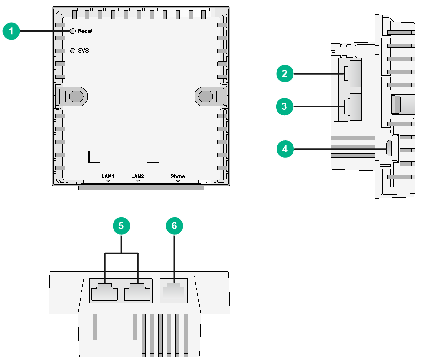
|
2: Uplink port (RJ-45) |
3: Uplink phone port |
|
|
4: Micro USB port |
5: 100M Ethernet port |
6: Downlink phone port |
Recommended device models
As a best practice, use wireless terminators and wireless terminator units, wall jack APs.
Typical networking schemes
Wireless medical scenarios have high requirements for signal coverage continuity and signal quality. Common applications in wireless medical scenarios include Internet access demands of ward users, wireless ward rounds, wireless device management, and handheld terminal applications. Though different handheld terminals have different NIC features and applications, they all have high requirements for wireless signal quality, stability, and seamless roaming.
In wireless medical scenarios, conventional networking or seamless roaming scheme can be used.
Medical staff access usually uses the ciphertext mode, and other access services can use plaintext or ciphertext mode.
Optimization guidelines and best practices
To help you select and deploy optimizations on an office WLAN, the optimization guidelines are categorized into the following types depending on their necessity:
· Required—Optimizations that you must deploy and in strict compliance with the requirements and guidelines.
· Strongly recommended—Top optimizations that help you improve network performance and user experience, especially when the WLAN performs poorly or requires high roaming experience. Deploy strongly recommended optimizations unless it has a negative impact on services or the customer requires to not deploy it.
· Recommended—Optimizations that might help you improve network performance and user experience. Deploy a recommended optimization unless it has a negative impact on services or the customer requires to not deploy it. After you deploy a recommended optimization, you must monitor the WLAN to make sure the deployment helps improve WLAN performance.
Increasing signal strength for the target coverage area (required)
Make sure the clients can receive a fair signal in the target coverage area. The minimum signal strength for medical clients is -65 dBm. Make sure the client RSSI values are 30 or higher on the APs.
To identify the RSSI value of client signals on APs, execute the display wlan client mac-address mac-address verbose command on their AC, and then examine the RSSI field in the command output.
Setting the channel plan and the working channels of APs (required)
Method 1 (hexagonal deployment):
This method is applicable to scenarios that have much traffic, much air interface resources, and few interference signals.
The coverage areas of APs might overlap in a high-density environment, resulting in signal interference between APs. WLAN performance would be low if all its APs operate on the same channel to share frequency resources.
To avoid adjacent channel interference, assign non-overlapping channels to adjacent APs. For example, use non-overlapping channels 1, 6, and 11 for channel assignment to 2.4 GHz radios on APs.
To avoid CCI on the same floor and between floors, use a hexagonal pattern for vertical and horizontal AP layout.
Make sure CCI is minimized when you manually assign working channels to AP radios.
As a best practice to increase channel isolation and reuse for higher WLAN performance, use 20 MHz or 40 MHz bandwidth mode for 802.11ac radios.
The default bandwidth mode for 802.11ac radios is 80 MHz. To change the bandwidth mode, use the channel band-width command.
Method 2 (channel-sharing deployment):
This method is applicable to scenarios that do not have much traffic but have many interference signals.
In actual deployment, some hospitals might have a large number of interference signals (such as service carrier devices, wireless monitoring devices, and private APs), which occupy many channel resources. If these interference signals cannot be avoided, you can configure APs on the same floor to use one channel with little interference. This deployment mode reduces the throughput but provides good roaming experience.
Setting the maximum transmit power of APs (required)
Tune AP transmit power on a per virtual WLAN basis.
By default, all APs transmit at the supported maximum transmit power.
To decrease co-channel interference between APs that operate on the same channel and maximize channel reuse, decrease the maximum transmit power of some APs on the same channel as appropriate.
As a best practice, do not enable transmit power control (TPC) to dynamically adapt AP transmit power to the real-time WLAN conditions. A client monitors all available signals for their signal strength. TPC might cause the clients to roam unnecessarily between APs, resulting in degraded user experience.
Using separate VLANs for WLAN services (required)
|
IMPORTANT: Wireless devices are mainly used for wireless access services. As a best practice, do not use wireless access controllers as the gateways of service VLANs in large integrated networks. |
A WLAN is a Layer 2 network that is typically broadcast and multicast intensive and is directly connected to the wired network.
To prevent the large amount of broadcast and multicast traffic from impacting the wired network, and confine attacks and the spread of viruses, use separate VLANs for WLAN services.
For clear network planning, use the WLAN as an access network, and monitor and control all traffic and access services through the existing wired network devices. Use wireless access controllers to configure the WLAN and manage wireless client access, and use existing wired devices as the gateways of service VLANs.
Downlink port isolation on wall jack APs/wireless terminator units (strongly recommended)
Broadcast storms caused by network cables between downlink ports or DHCP address allocation conflicts caused by private routers might occur on wall jack APs or wireless terminator units. These problems will reduce user experiences. Therefore, you need to configure Layer 2 isolation on the wired downlink ports of wall jack APs or wireless terminator units by assigning these ports to different VLANs. However, VLAN resources are limited, so configure the port isolation feature as a best practice. With port isolation, you only need to add the ports to the isolation groups to realize Layer 2 isolation between these ports. As a result, the VLAN resources are saved. As a best practice, enable port isolation on the downlink ports of all upstream switches of wall jack APs or wireless terminator units to avoid unnecessary flooding that occurs after the MAC address table resources are used up.
Enabling roaming navigation (strongly recommended)
Wireless protocols do not provide a roaming mechanism, so the roaming time and method are completely determined by a wireless client itself. A wireless client can listen to beacon frames to select an AP when roaming. To select the best AP to roam to, the client must listen to beacon frames for a beacon interval in each supported channel. A wireless client can also sends probe requests and then select the best AP to roam to based on the probe responses received from the APs.
The roaming navigation feature decreases the transmit power for beacons or probe responses of an AP to enable clients on the AP to roam to APs with better signal strength.
Isolating SSIDs of different floors (strongly recommended)
The key part of a medical scenario is the deployment of the ward area, and main users include nurses and doctors. Nurses usually use handheld terminals, which are time sensitive and have a small amount of data access and a fast movement speed. Doctors usually use trolleys, which are time insensitive and have a large amount of data access and a slow movement speed. At present, most handheld terminals have poor roaming quality. In a hospital, the wireless terminals of a department are usually used only in the ward area of the department and roaming across floors is barely required. As a best practice, isolate the SSIDs of different floors to prevent wireless terminals from roaming between floors.
· When the unified SSID mode is used, a wireless terminal will select an AP from all APs with the same SSID when roaming. Therefore, it is easy for wireless terminals to roam between floors in the unified SSID mode, but the roaming experience provided by this mode is poor.
· When the SSID isolation method is used, a wireless terminal will select an AP from only APs with the same SSID on the same floor when roaming, which greatly improves the roaming experience.
Isolating the clients in a VLAN at Layer 2 (strongly recommended)
All APs in a VLAN receive the broadcast and multicast packets from all clients in that VLAN. Because a client typically sends broadcast and multicast packets at the minimum rate, user experience will decrease as the number of broadcasts increase to occupy radio resources.
Use the following best practices to reduce broadcast and multicast traffic on the WLAN for better performance:
· Configure the AC to disable the clients in the same VLAN to communicate directly with each other and enable all clients to communicate with each other through their respective gateways.
· Use the undo user-isolation permit-broadcast command to disable forwarding broadcast and multicast traffic from wired users to wireless users except the wired users specified by using the user-isolation vlan permit-mac command.
In this situation, the wireless clients can still send broadcast and multicast traffic to wired users.
When you configure intra-VLAN user isolation, use the following guidelines:
· If the network has a VRRP deployment, the permitted MAC list configured by using the user-isolation vlan permit-mac command must include the virtual and real MAC addresses of the VRRP gateway.
· When the APs or wireless terminators (WTs) on the WLAN perform local forwarding, you must issue intra-VLAN user isolation settings to the APs or the WTs.
· Configure the peer ports between the AC and the switches to permit only VLANs required for communication. Avoid using the permit vlan all command to assign the ports to all VLANs.
Disabling low rates (strongly recommended)
Each WLAN standard supports a set of data rates. For example, 802.11g supports 1, 2, 5.5, 11, 6, 9, 12, 18, 24, 36, 48, and 54 Mbps. Typically, wireless devices (for example, clients and APs) send frames at a rate dynamically selected from the rate set supported on the WLAN. When sending broadcasts and management frames, they typically use the lowest data rate (1 Mbps). This mechanism causes inefficient use of radio resources and degraded user experience when a large amount of broadcast traffic is present.
To improve radio use efficiency for better experience:
· Disable low data rates 1, 2, 5.5, 6, and 9 Mbps in a typical indoor deployment.
Most indoor deployments provide a good signal to clients in the coverage area. Disabling low data rates are unlikely to cause packet drops that might occur because the received signal of clients is weak or the clients is far away from the APs.
· If some of the clients cannot associate with an AP even though they can detect the signal from that AP, restore the default transmission rate setting on the AP radio.
For example, an 802.11b radio supports 5.5 Mbps and 11Mbps by default. If disabling these two rates might prevent some clients from associating to the AP, restore the default transmission rate setting.
Rate-limiting clients (strongly recommended)
The bandwidth of an AP is shared among its associated clients. To prevent aggressive use of bandwidth by some clients from affecting other clients, set a rate limit on clients.
When you configure client rate limiting, use the following guidelines:
· Use client rate limiting or intelligent bandwidth guarantee, but not both.
· You can configure a client rate limit both on a radio and in the service template bound to that radio. In this situation, the lower value between the two limit settings applies to the template-matching clients on that radio.
Rejecting weak-signal clients (recommended)
|
IMPORTANT: · If the signal strength of a client becomes lower than the threshold after it is associated, the AP will not terminate the connection to the terminal. However, the client cannot reassociate with the AP after it goes offline. · In a wireless network using the 5.8 GHz technology, the 5.8 GHz signal strength of the APs is relatively weak. Therefore, you must analyze the signal strength (RSSI) of all wireless clients and then configure an appropriate threshold when configuring this feature. In scenarios that contain weak-signal clients, enabling this feature might cause client access failures. Please be cautious. |
Although wireless clients with weak signals can access the WLAN, the network performance and service quality that they can obtain are much worse than those with strong signals. If a wireless client with weak signals is downloading a large amount of data in the WLAN, the network performance of other wireless clients will be greatly affected.
This feature enables an AP to reject clients with an RSSI lower than the specified threshold to release channel resources and enhance WLAN performance.
Enabling AP-triggered client reassociation (recommended)
|
IMPORTANT: In a wireless network using the 5.8 GHz technology, the 5.8 GHz signal strength of the APs is relatively weak. Therefore, you must analyze the signal strength (RSSI) of all wireless clients and then configure an appropriate threshold when configuring this feature. In scenarios that contain weak-signal clients, enabling this feature might cause client access failures. Please be cautious. |
A client with a low signal strength can roam to another AP only when its signal strength is lower than the manufacturer-defined signal strength for triggering roaming. Therefore, the client cannot obtain good network experience and service quality.
After you enable AP-triggered client reassociation for an AP, the AP sends unsolicited deauthentication frames to a client when the signal strength of the client is lower than the specified RSSI threshold. Then, the client can reassociate with the AP or roam to another AP.
Probe frame and beacon frame control (recommended)
A wireless client can listen to beacon frames to select an AP when roaming. To select the best AP to roam to, the client must listen to beacon frames for a beacon interval in each supported channel. Therefore, you can reduce the beacon frame sending interval to enable wireless clients to roam quickly. A wireless client can also sends probe requests and then select the best AP to roam to based on the probe responses received from the APs.
· Reducing the beacon frame sending interval
By default, each SSID on a radio send a beacon frame every 100 TU to advertise its access service and synchronize information with the wireless NIC. To select the best AP to roam to, a wireless client must listen to beacon frames for a beacon interval in each supported channel. Therefore, you can reduce the beacon frame sending interval to 60 TU to enable wireless clients to roam quickly.
The air interface overhead will be increased after you reduce the beacon frame sending interval. As a best practice, do not configure more than two SSIDs on a radio.
To set the beacon frame sending interval, execute the beacon-interval command.
· Enabling APs to respond to broadcast probe requests
By default, an AP can respond to broadcast probe requests. To disable an AP from responding to broadcast probe requests, execute the broadcast-probe reply disable command.
|
|
NOTE: As a best practice, do not disable APs from responding to broadcast probe requests in medical scenarios as the H3C roaming navigation feature is implemented based on probe frames. |
Configuring encryption for increased performance (strongly recommended)
Encryption introduces time overheads for key negotiation.
To reduce encryption time overheads for better radio performance, do not use encryption on a radio.
If you must use encryption on an 802.11ac WLAN, use the following guidelines:
· Use the CCMP cipher suite in RSN security mode as a best practice.
· Avoid using the TKIP or a WEP cipher suite as long as possible.
TKIP and WEP cipher suites are insecure and the client's data rate cannot exceed 54 Mbps when WEP or TKIP encryption is used.
Troubleshooting
Weak signal from some APs or antennas
Symptom
The wireless signals received by clients associated with some APs or antennas are weak.
Solution
To resolve the issue: Identify the distance between the client and AP. Identify whether the client receives weak signals from a single antenna, single AP, or all APs. Check antenna installation or replace the antenna if the client receives weak signals from a single antenna. If the client receives weak signals from a single AP, examine the AP to verify that a load has been attached to the external antenna on the AP, or replace the AP. If the client receives weak signals from all APs, consider antenna type, antenna cable type, and cable length issues.
Outdoor deployment
You can deploy outdoor APs in wireless coverage mode (non mesh) or bridge mode (mesh).
Wireless coverage
To achieve wide coverage, you can use the wireless coverage mode in scenarios such as school playgrounds, open fields, parks, scenic spots, city streets, airports, train stations, stadiums, and wireless video surveillance.
Site survey guidelines
Choose outdoor APs as a best practice, and choose outdoor directional or omnidirectional antennas. Determine the most suitable antenna type and installation position based on coverage distance, coverage area, installable height, and AP spacing. Take cabling, pole reinforcement, grounding, weatherproofing, and lightning protection in full consideration.
Design considerations
The following are the items to consider when you design and build a WLAN with outdoor APs:
· Ensure effective signal transmission between the AP and the wireless endpoints. When the antenna transmit power is guaranteed and the received signal strength of the terminal is satisfied, you must also consider the signal strength of the wireless endpoints. In outdoor scenarios, smart terminals such as mobile phones are typically used, and they have higher signal strength and quality requirements than wireless network card terminals such as notebooks. As a best practice, increase AP density to ensure that the minimum RSSI at the cell boundaries is –65 dBm.
· Consider adjusting the azimuth and downtilt of the antennas in areas with overlapping signals.
· For better coverage, make sure the direction of the main beam of the antenna faces the coverage area directly.
· Avoid co-channel interference through natural environment attenuation such as walls and ceilings.
· To avoid interference caused by overlapping antenna main lobes of the same channel, adjust the antenna azimuth.
· Make sure the coverage area is as close to the antenna of the AP as possible, and there is a straight line of sight between the AP’s antenna and the coverage area.
Deployment methods
In outdoor deployment, antenna type, installation position and height, and AP layout affect the signal coverage. You can use the following deployment methods as needed:
· Install omnidirectional antennas at the center of the coverage area. This mode is applicable to generic coverage areas without specific coverage objects.
· Place an omnidirectional antenna at a high position and make sure the antenna has a certain downtilt angle. This mode is applicable to scenarios where wireless coverage is required on specific objects.
· Install a directional antenna on one building to cover the opposite building.
Site survey guidelines
· Perform an on-site survey and test with different parties.
· Determine the AP position, AP quantity and model, power supply mode, antenna type, and antenna installation position.
· Make sure all required accessories such as pole, mounting kit, power cable, network cable, and antenna cable have been prepared.
· Use weather-proof tapes or glues to weather proof the antenna ports and network ports by following the installation guide.
· You can install outdoor APs on a pole or on a wall through a wall mounting bracket. Select appropriate installation positions and heights as required by the installation site.
· Attach lightning protection equipment between an antenna and an AP, and take lightning protection measures by following the installation guide.
· Make sure the front of a directional antenna faces the wireless endpoints. As a best practice, install an omnidirectional antenna 5 m (16.40 ft) high, and a directional antenna 7 to 8 m (22.97 to 26.25 ft) high. Make sure there is an unobstructed line of sight between the antenna and wireless endpoints.
Use cases
Business streets


Business streets are the most active areas of Wi-Fi networks. Consider not only business model and customization requirements of stores but also signal interference, because the Wi-Fi networks deployed on business streets might be affected by the Wi-Fi networks deployed in the stores.
To mitigate signal interference, you can plan the working channels or make use of obstacles to isolate APs. In addition, you must consider aesthetics and blend the APs and antennas into the environment
WLAN deployment at business streets not only provides Internet access but also services such as product recommendation and guidance, geographic location guidance, public service resource inquiry, and online shopping.
Public leisure areas

Public leisure areas typically have an open space, and have dense trees in some places. Human activities are sometimes dense and sometimes sparse. Therefore, deploy APs at places where people are easy to gather, as well as places where people can stop and rest. You can install APs on nearby buildings, street lights, and service provider signal towers, or on a pole. Use directional antennas, and make sure the main lobes face the target coverage area.
WLAN deployment in public leisure areas not only satisfies Internet access requirements but also provides city security control functions such as wireless monitoring and asset positioning.
Urban arteries

WLAN deployment on urban arteries can help police patrol, monitoring, and Internet access on buses.
In addition to deploying APs for client access, you can also deploy mesh APs that support MLSP used for subway WLAN deployment. This deployment mode has rather high cost but provides more stable wireless links. If you use MLSP, select the 5 GHz band as a best practice.
Urban scenic areas

Taking into account aesthetics, culture, and value of the relics, avoid damage as much as possible when installing APs. You can hide APs or install APs outside the scenic spot and use directional antennas to achieve signal coverage. You can use ANT-2503CM indoor antennas to meet the aesthetic requirements.
Urban viaducts and belt highways

Bridges, viaducts, and belt highways have large traffic flows. In this scenario, WLANs can be deployed for monitoring, ETC, and highway patrol. Select appropriate installation positions and directional antennas and consider AP spacing and engineering requirements when deploying APs.
Urban residential streets

In this scenario, applications such as parking area management, wireless monitoring, and public information inquiry can not only improve informatization of the city, but also help improve the security protection and control capabilities such as anti-terrorism and emergency sheltering.
AP and antenna selection
Order outdoor APs as a best practice. For some APs, you must also order external antennas.
· Ordering APs
In a high-density environment, for example, entrance of scenic spot, railway station, airport, and waiting hall, select dual-band or triple-band APs because more and more wireless endpoints support 5G.
· Ordering antennas
Use omnidirectional antennas if you provide Wi-Fi coverage for multiple wireless endpoints and these wireless endpoints are located at multiple directions from the AP. Use directional antennas if they are located in the same direction of the AP. In addition, you must consider antenna connector compatibility with APs and whether the gains of the antennas meet the requirement.
Troubleshooting
A client goes offline frequently
Symptom
A client goes offline frequently.
Solution
To resolve the issue:
a. View the signal strength of the client and make sure the client has a minimum of medium level signal (3 bars) and verify that the RSSI value of the client is not lower than 20 on the AP.
b. If the signal strength of the endpoint or AP is weak, move the endpoint closer to the AP. If the signal strength has an obvious increase, the designed coverage of the AP might be too large or the NIC of the endpoint has a low power and you must add more APs. In an open environment, the coverage of an outdoor AP installed with a directional antenna is 50 to 100 meters.
c. Move the wireless endpoint within the coverage of the AP. If the signal strength is strong in some directions but weak in other directions, the azimuth of the antenna might be incorrect. Change the azimuth and try again.
d. Verify that the antenna is installed correctly and antenna type is correct if the signal strength of the client remains weak.
An AP goes offline frequently
Symptom
An AP goes offline frequently.
Solution
To resolve the issue:
a. Execute the display wlan ap name ap-name verbose command on the AC to verify that the Online time and System up time are the same. If they are not the same, check the Last reboot reason and Tunnel down reason fields for the AP restart reason and registration tunnel down reason.
[AC] display wlan ap name ap1 verbose
AP name : ap1
AP ID : 1
AP group name : default-group
State : Run
Backup type : Master
Online time : 7 days 1 hours 25 minutes 12 seconds
System uptime : 7 days 2 hours 22 minutes 12 seconds
……
Last reboot reason : User soft reboot
Last reboot reason (AP check) : The radio physical status was down
Last reboot reason (AC check) : The radio physical status was down
Latest IP address : 10.1.0.2
Current AC IP : 192.168.1.1
Tunnel down reason : Request wait timer expired
……
b. Determine the AP offline reason based on the registration tunnel down reason. If the device had restarted, you must check detailed device restart reason.
c. If the last reboot reason of the AP is Power on, consider whether the power source can provide sufficient and stable power supply.
Outdoor APs can be powered through PoE or a local power source. Outdoor APs are typically deployed far from equipment rooms. Therefore, they are typically powered through a local power source. To ensure stable power supply to outdoor APs through PoE, use PoE+ or PoE++.
d. Verify that grounding measures have been taken for outdoor antennas. Poor grounding might cause frequent wired port up and down.
Wireless bridging
In this mode, APs are configured to build a wireless mesh network where wired network cabling is not available. Wireless bridging connects two independent LANs through wireless bridges to transmit data between them. Wireless bridging provides the following benefits:
· Low cost and high performance.
· Expandable, without requiring new wired connections and more APs.
· Applicable to subways, companies, large warehouses, manufacturing industry, and harbors.
Site survey
Pre-survey check
Perform the following tasks before a site survey.
· Determine the link distance and whether external antennas are required. Select appropriate antennas based on the gain and lobe coverage. You can test antennas with different gains and select an optimal one.
· Determine whether obstacles exist in the coverage of the mesh network and whether WLAN access service is required.
· Determine the working mode of mesh APs: mesh link establishment between fat APs, between fit APs, or between fat AP and fit AP. Determine whether there is high-speed movement of APs at either end. If yes, consider fast switching of bridge signals.
· Determine wired traffic size and make sure no other signals exist at the 5 GHz band.
· Determine the power supply mode, PoE or local of the APs at the two ends of a mesh link.
· Select appropriate network cables or fibers.
Site survey guidelines
· Ensure an unobstructed line of sight between two APs in a point-to-point bridging deployment. For long-haul bridging, you can use the LEDs on APs to help adjust the azimuth of the APs or you can use some auxiliary methods, for example, use telescopes, flashlights, or even professional signal analysis equipment for point-to-point connection debugging.
· Take grounding and lightning protection measures and use weather-proof tapes or glue to weather proof the antenna ports and network ports by following the installation guide.
· You can install outdoor APs on a pole or on a wall through a wall mounting bracket. Select appropriate installation positions and heights as required by the installation site.
· Prepare test terminals and Wi-Fi analysis software to test interference at the site.
AP and antenna selection
For short-distance bridging, you can select both indoor APs and outdoor APs.
For long-distance bridging, select outdoor APs as a best practice. For some APs, you must also order outdoor antennas.
For the rail transportation scenario, order APs dedicated for rail transportation.
Application scenarios
Wireless bridge mode requires link stability and bandwidth. You can select antennas with different gains for mesh links with different distances. As a best practice, use point-to-point bridging.
Using fat APs to establish mesh links for multiple deployments will increase maintenance complexity and workload. As a best practice, use fit APs for WLAN mesh deployment.
In a scenario where the APs at one end are moving and the APs at the other end are not, for example, in a subway deployment, select the fat-fit AP mode. Deploy fat APs at the moving end, and connect them to wired devices such as switches and servers. Deploy fit APs at the other end, and connect them to the access controller through a wired network. The fit APs establish wireless connections with the fat APs through mesh links to transmit wired traffic from the fat APs to the fit APs. In this scenario, fat APs are moving and will connect and disconnect from different fit APs frequently. You must ensure smooth mesh link switching and avoid loops between fit APs.
Troubleshooting
No mesh link can be established
Symptom
No mesh links can be established in a WLAN mesh network.
Solution
To resolve the issue:
a. Verify that the basic settings are correct.
b. Verify that the blacklist and whitelist configured using the mesh peer-mac-address command are correct.
c. Perform the following steps to debug the mesh link establishment process:
d. Verify that the interface for mesh link establishment can send Beacon frames and receive wireless frames successfully.
e. Execute the display ar5drv 1 statistics command multiple times to identify whether the values of RxFrameCnt and BeaconIntCnt increase.
- If the value of BeaconIntCnt increases, the basic settings at the local end are correct. If the value of RxFrameCnt increases, the local AP might have received frames sent by the peer end.
- If the value of BeaconIntCnt does not increase, the local settings are not correct.
- If the value of RxFrameCnt does not increase or is always 0, the settings of the peer end might be incorrect or the antenna installation or direction of the peer end might be incorrect.
[AP-hidecmd]display ar5drv 1 statistics
Radio statistics:
Transmit statistics
TxFrameAllCnt : 130376
TxFrameAllBytes : 14294996
……………………………………………………………………………………………………
Receive statistics
RxFrameAllCnt : 372824
RxFrameCnt : 151777
RxFrameBytes : 15289882
InDiscards : 0
InputErrs : 221047
FcsErrCnt : 101
TooLongErrs : 0
UnderrunErrs : 0
OverrunErrs : 0
ReachRxTail : 0
DecryptErr : 0
DecryptCRCErrs : 0
KeyCacheMiss : 0
MichaelErrs : 0
Beacon statistics
BeaconIntCnt : 102975
BeaconBusyCnt : 1
BeaconErrCnt : 0
………………………………………………………………………………
f. Execute the debugging wlan mesh { all | error | event | frame { send | receive } [ verbose ] | fsm | ha | security | timer } command.
If other links are running, enable debugging functions except for frame.
g. Use AirMagnet Survey to scan mesh signals. The scanned signal represents an Ad-hoc device. You can verify the MAC address of the device or use AirMagnet Survey to capture packets to determine whether the device has sent packets successfully. If no packets can be received, the settings at the peer end are incorrect, the antenna is connected incorrectly, or the direction of the antenna is incorrect. If signals can be received, you can identify whether the signal strength is reasonable.
Use Omnipeek to capture packets at the end that cannot find a neighbor to determine whether probe requests and beacon frames can be captured.
For example, if two APs cannot establish mesh links, you can configure a radio of one AP to provide access service, and use a laptop where the other AP is located to test whether it can receive signals from the AP.
If the laptop cannot discover the network, the settings at the peer end are incorrect, the antenna is connected incorrectly, or the direction of the antenna is incorrect.
Mesh links are disconnected frequently
Symptom
Mesh links are disconnected frequently.
Solution
To resolve the issue:
a. Execute the display wlan mesh-link command to display the signal strength of mesh links.
<AP> display wlan mesh-link
Peer MAC RSSI BSSID Interface Link state Online time
4a1b-517d-23ff 22 6a3b-cc5a-e215 WLAN-MeshLink1 Active(an) 00h 08m 31s
For a stable mesh link to be established, the RSSI must be greater than 20. If the RSSI remains at a low value, verify the antenna azimuth and installation.
b. Execute the display ar5drv 1 channelbusy command in probe view to identify whether a channel is busy.
[ap-hidecmd]display ar5drv 1 channelbusy
ChannelBusy information
Ctl Channel:11 Channel Band:20M
Ext Channel:
Record Interval(s): 9
Date/Month/Year:09/02/2017
Time(h/m/s): CtlBusy(%) TxBusy(%) RxBusy(%) ExtBusy(%)
01 13:37:39 19 2 15 0
02 13:37:30 18 2 13 0
03 13:37:22 17 2 13 0
04 13:37:13 18 2 14 0
05 13:37:04 20 2 16 0
06 13:36:54 18 2 14 0
07 13:36:45 16 2 12 0
08 13:36:36 12 2 8 0
09 13:36:27 14 2 10 0
10 13:36:18 12 2 8 0
11 13:36:09 15 2 12 0
12 13:36:00 12 2 8 0
13 13:35:51 21 2 17 0
14 13:35:42 24 1 18 0
As a best practice, establish mesh links at the 5 GHz band because the 2.4 GHz band is easy to be interfered. If the value of Rxbusy exceeds 20%, co-channel interference has occurred. Change to another channel to identify whether a mesh link can be established.
Workaround
· To avoid interference, use the 5 GHZ band as a best practice.
· Avoid using radar channels 52, 56, 60, and 64.
· Make sure the RSSI of the APs is greater than 30.
