- Table of Contents
- Related Documents
-
| Title | Size | Download |
|---|---|---|
| 02-H3C WLAN Star-Topology IRF Deployment Guide | 224.72 KB |
|
H3C WLAN Star-Topology IRF |
|
Deployment Guide |
New H3C Technologies Co., Ltd.
http://www.h3c.com
Document version: 6W100-20220830
Software and hardware compatibility with star-topology IRF
IRF fabric of directly connected two ACs
IRF fabric of Layer 2 network connected AC devices
AC module IRF fabric hosted in chassis
How many member devices can an AC IRF fabric contain?
What are the requirements for the software version of member devices in an IRF fabric?
In what situations should I use intermediate devices to connect IRF member devices?
What are the requirements for IRF topo-domain IDs?
Introduction
Overview
Star-topology IRF virtualizes multiple ACs that have Layer 2 connectivity into one virtual node called an IRF fabric. The IRF fabric unifies the hardware resources and software processing capabilities of the ACs, and enables unified management and uninterrupted maintenance.
An IRF fabric appears as one node and is accessible at a single IP address on the network. You can use this IP address to log in at any member device to manage all the members of the IRF fabric.
As a best practice to streamline the topology and decrease administrative complexity in a complex network environment, use star-topology IRF instead of the dual-AC link backup solution.
Concepts
IRF member roles
IRF uses two member roles: master and standby.
When devices form an IRF fabric, they elect a master to manage and control the IRF fabric, and all the other devices back up the master. When the master device fails, the other devices automatically elect a new master.
IRF member ID
An IRF fabric uses member IDs to uniquely identify and manage its members.
Two devices cannot form an IRF fabric if they use the same member ID. A device cannot join an IRF fabric if its member ID has been used in the IRF fabric.
Member priority
Member priority determines the possibility of a member device to be elected the master. A member with higher priority is more likely to be elected the master.
IRF port
An IRF port is a logical interface that forwards data and IRF control packets between IRF member devices.
Every IRF-capable device has one IRF port. The IRF port is numbered by the IRF member ID of the device.
An IRF port must contain a minimum of one channel to send data and control packets.
IRF links
Links of the network interfaces bound to IRF ports are called IRF links.
You can configure an IRF link as one of the following channels:
· Control channel—The link forwards only IRF control packets between member devices.
· Data channel—The link forwards only data packets between member devices.
· Hybrid channel—The link forwards both control and data packets.
IRF topo-domain ID
An IRF topo-domain ID uniquely identifies an IRF fabric. Devices must have the same IRF topo-domain ID to form one IRF fabric.
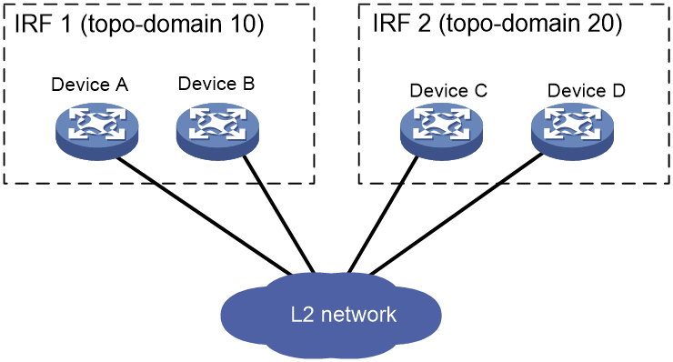
As shown in Figure 1, IRF fabric 1 contains Device A and Device B, and IRF fabric 2 contains Device C and Device D. The IRF fabrics can reach each other at Layer 2. When a member device receives a packet from an IRF link, it checks the topo-domain ID to determine whether the packet is from the local IRF fabric. Then, the member device can handle the packet correctly.
Figure 1 A network that contains two IRF topo-domains
IRF merge and split
IRF merge occurs when two split IRF fabrics reunite or when two independent IRF fabrics are united.
IRF split occurs when an IRF fabric breaks up into multiple IRF fabrics when Layer 2 connectivity is lost. The split IRF fabrics operate with the same IP address. IRF split causes routing and forwarding issues on the network.
Configuration synchronization
An IRF fabric runs with the running configuration on the master device. The master device synchronizes its running configuration to all other IRF member devices.
IRF configuration synchronization includes batch synchronization at initialization and real-time synchronization during the runtime.
IRF multi-active detection
Star-topology IRF provides MAD mechanisms by extending LACP to detect multi-active collisions.
The IRF member devices send extended LACPDUs that convey a MAD domain ID and an active ID (the member ID of the master). The intermediate device transparently forwards the extended LACPDUs received from one member device to all the other member devices.
· If the MAD domain IDs and active IDs sent by all the member devices are the same, the IRF fabric is integrated.
· If the extended LACPDUs convey the same MAD domain ID but different active IDs, a split has occurred.
IRF software auto-update
IRF provides the software auto-update feature. With this feature, you do not need to manually update a device with the software version running on an IRF fabric before you add the device to the IRF fabric. The device will automatically update the software as long as its software version is compatible with the one running on the IRF fabric.
When you add the device to the IRF fabric, the device compares its software version with that of the master. If the versions are not the same, it automatically downloads startup software images from the master, reboots with the new startup software images, and joins the IRF fabric again.
If the device does not support software auto-update, you must manually update it with the software version running on the IRF fabric before you add it to the IRF fabric.
Network model
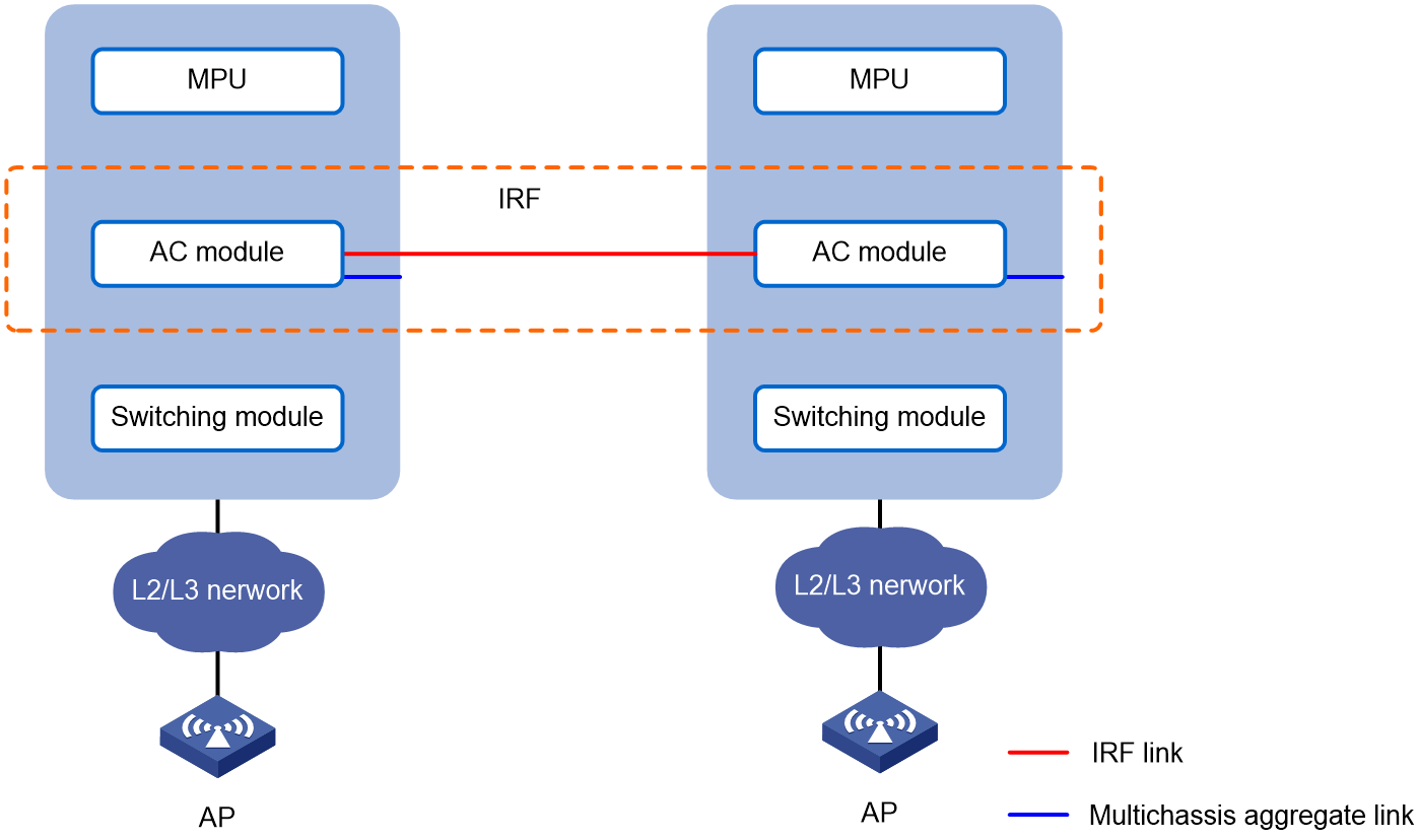
On an IRF fabric, the master device manages and controls the resources on all member devices.
Figure 2 IRF network model

Software and hardware compatibility with star-topology IRF
|
|
IMPORTANT: Support for device models varies by country and region. For more information, contact local H3C representatives or engineers. |
License sharing
The ACs in an IRF fabric share their licenses. The licenses running before a master/standby switchover continue to take effect after the switchover.
If the IRF fabric splits, the shared licenses will continue to take effect on the member ACs for 30 days. If the member ACs do not merge after 30 days, they will run only their own licenses.
Deployment models
An AC comes in the form of a standalone device or a service module.
The following are typical deployments for AC devices or AC modules:
· IRF fabric of directly connected two ACs
· IRF fabric of Layer 2 network connected AC devices
· AC module IRF fabric hosted in chassis
IRF fabric of directly connected two ACs
Network configuration
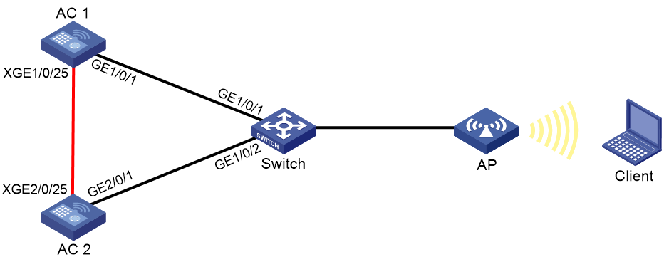
As shown in Figure 3:
· Set up a direct IRF connection between two AC devices.
· Establish a dynamic dual-AC link aggregation with the remote switch to run LACP MAD.
Figure 3 IRF fabric of directly connected two ACs
Procedure
Configuring the switch
# Create Layer 2 aggregate interface Bridge-Aggregation 1, and configure the aggregation group of the aggregate interface to operate in dynamic mode.
<Switch> system-view
[Switch] interface bridge-aggregation 1
[Switch-Bridge-Aggregation1] link-aggregation mode dynamic
[Switch-Bridge-Aggregation1] quit
# Assign GigabitEthernet 1/0/1 to aggregation group 1.
[Switch] interface gigabitethernet 1/0/1
[Switch-GigabitEthernet1/0/1] port link-aggregation group 1
[Switch-GigabitEthernet1/0/1] quit
# Assign GigabitEthernet 1/0/2 to aggregation group 1.
[Switch] interface gigabitethernet 1/0/2
[Switch-GigabitEthernet1/0/2] port link-aggregation group 1
[Switch-GigabitEthernet1/0/2] quit
# Enable link-aggregation traffic redirection.
[Switch] link-aggregation lacp traffic-redirect-notification enable
Configuring AC 1
# Assign Ten-GigabitEthernet 1/0/25 to IRF-port 1.
<AC1> system-view
[AC1] irf-port 1
[AC1-irf-port1] port group interface ten-gigabitethernet 1/0/25
[AC1-irf-port1] quit
# Set the member priority to 2. AC 1 will be the master device.
[AC1] irf member 1 priority 2
# Save the configuration.
[AC1] save
The current configuration will be written to the device. Are you sure? [Y/N]:y
Please input the file name(*.cfg)[cfa0:/startup.cfg]
(To leave the existing filename unchanged, press the enter key):
Validating file. Please wait...
Saved the current configuration to mainboard device successfully.
# Activate the IRF port configuration.
[AC1] irf-port-configuration active
Configuring AC 2
# Change the IRF member ID to 2.
<AC2> system-view
[AC2] irf member 1 renumber 2
Renumbering the member ID may result in configuration change or loss. Continue?[
Y/N]:y
[AC2] quit
# Reboot the AC for the new member ID to take effect.
<AC2> reboot
Start to check configuration with next startup configuration file, please wait..
.......DONE!
Current configuration may be lost after the reboot, save current configuration?
[Y/N]:y
Please input the file name(*.cfg)[cfa0:/startup.cfg]
(To leave the existing filename unchanged, press the enter key):
cfa0:/startup.cfg exists, overwrite? [Y/N]:y
Validating file. Please wait...
Saved the current configuration to mainboard device successfully.
This command will reboot the device. Continue? [Y/N]:y
Now rebooting, please wait...
# Assign Ten-GigabitEthernet 2/0/25 to the IRF port.
<AC2> system-view
[AC2] irf-port 2
[AC2-irf-port2] port group interface ten-gigabitethernet 2/0/25
[AC2-irf-port2] quit
# Save the configuration.
[AC2] save
The current configuration will be written to the device. Are you sure? [Y/N]:y
Please input the file name(*.cfg)[cfa0:/startup.cfg]
(To leave the existing filename unchanged, press the enter key):
Validating file. Please wait...
Saved the current configuration to mainboard device successfully.
# Activate the IRF port configuration.
[AC2] irf-port-configuration active
System is starting...
AC 1 and AC 2 perform master election. AC 2 fails master election and reboots to form an IRF fabric with AC 1.
Configuring the IRF fabric
# Change the name of the IRF fabric to IRF.
<AC1> system-view
[AC1] system-name IRF
# Configure descriptions for AC 1 and AC 2.
[IRF] irf member 1 description AC 1
[IRF] irf member 2 description AC 2
# Create a Layer 2 aggregate interface named Bridge-Aggregation 1, and set the aggregation mode to dynamic mode.
[IRF] interface bridge-aggregation 1
[IRF-Bridge-Aggregation1] link-aggregation mode dynamic
# Enable LACP MAD on the aggregate interface.
[IRF-Bridge-Aggregation1] mad enable
[IRF-Bridge-Aggregation1] quit
# Enable link-aggregation traffic redirection.
[IRF] link-aggregation lacp traffic-redirect-notification enable
# Assign GigabitEthernet 1/0/1 to aggregation group 1.
[IRF] interface gigabitethernet 1/0/1
[IRF-GigabitEthernet1/0/1] port link-aggregation group 1
[IRF-GigabitEthernet1/0/1] quit
# Assign GigabitEthernet 2/0/1 to aggregation group 1.
[IRF] interface gigabitethernet 2/0/1
[IRF-GigabitEthernet2/0/1] port link-aggregation group 1
[IRF-GigabitEthernet2/0/1] quit
Verifying the configuration
# Display IRF information. Verify that AC 1 is the master device.
[IRF] display irf
Member ID Role Priority CPU MAC Description
*1 Master 2 50da-0051-2608 AC 1
+2 Standby 1 50da-0051-2670 AC 2
--------------------------------------------------
The asterisk (*) indicates the master.
The plus sign (+) indicates the device through which you are logged in.
The right angle bracket (>) indicates the device's stack capability is disabled.
Bridge MAC of the IRF: 50da-0051-2608
Auto upgrade : Enabled
MAC persistence : 6 min
Topo-domain ID : 0
Auto merge : Enabled
# Display IRF link information. Verify that the IRF network interfaces on both member devices are up.
[IRF] display irf link
Member ID Member Interfaces Status
1 XGE1/0/25(ctrl&data) Up
2 XGE2/0/25(ctrl&data) Up
# On the IRF fabric, display detailed information about aggregation groups. Verify that GigabitEthernet 1/0/1 and GigabitEthernet 2/0/1 are in aggregation group 1 and in Selected state.
[IRF] display link-aggregation verbose
Loadsharing Type: Shar -- Loadsharing, NonS -- Non-Loadsharing
Port Status: S -- Selected, U -- Unselected, I -- Individual
Flags: A -- LACP_Activity, B -- LACP_Timeout, C -- Aggregation,
D -- Synchronization, E -- Collecting, F -- Distributing,
G -- Defaulted, H -- Expired
Aggregate Interface: Bridge-Aggregation1
Aggregation Mode: Dynamic
Loadsharing Type: Shar
System ID: 0x8000, 50da-0051-2608
Local:
Port Status Priority Oper-Key Flag
--------------------------------------------------------------------------------
GE1/0/1 S 32768 1 {ACDEF}
GE2/0/1 S 32768 1 {ACDEF}
Remote:
Actor Partner Priority Oper-Key SystemID Flag
--------------------------------------------------------------------------------
GE1/0/1 1 32768 1 0x8000, 3897-d633-f3c6 {ACDEF}
GE2/0/1 2 32768 1 0x8000, 3897-d633-f3c6 {ACDEF}
# On the switch, display detailed information about aggregation groups. Verify that GigabitEthernet 1/0/1 and GigabitEthernet 1/0/2 are in aggregation group 1 and in Selected state.
[Switch] display link-aggregation verbose
Loadsharing Type: Shar -- Loadsharing, NonS -- Non-Loadsharing
Port Status: S -- Selected, U -- Unselected,
I -- Individual, * -- Management port
Flags: A -- LACP_Activity, B -- LACP_Timeout, C -- Aggregation,
D -- Synchronization, E -- Collecting, F -- Distributing,
G -- Defaulted, H -- Expired
Aggregate Interface: Bridge-Aggregation1
Aggregation Mode: Dynamic
Loadsharing Type: Shar
Management VLAN : None
System ID: 0x8000, 3897-d633-f3c6
Local:
Port Status Priority Oper-Key Flag
--------------------------------------------------------------------------------
GE1/0/1 S 32768 1 {ACDEF}
GE1/0/2 S 32768 1 {ACDEF}
Remote:
Actor Partner Priority Oper-Key SystemID Flag
--------------------------------------------------------------------------------
GE1/0/1 2 32768 1 0x8000, 50da-0051-2608 {ACDEF}
GE1/0/2 31 32768 1 0x8000, 50da-0051-2608 {ACDEF}
IRF fabric of Layer 2 network connected AC devices
Network configuration
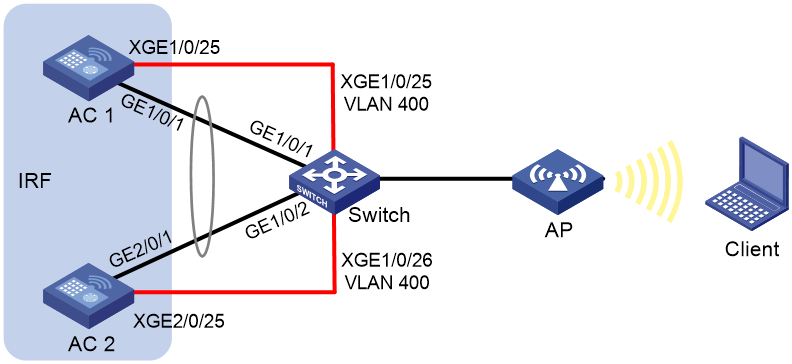
As shown in Figure 4:
· Set up an IRF connection between two AC devices over a switch.
· Establish a dynamic dual-AC downlink aggregation with the switch to run LACP MAD.
To isolate traffic, assign the IRF link and the aggregate link for user connectivity to different VLANs. In this example, the IRF link is assigned to VLAN 400.
Figure 4 IRF fabric of Layer 2 network connected AC devices
Procedure
Configuring the switch
1. Configure links for interfaces connected to the IRF network interfaces:
# Create VLAN 400 and assign the physical interfaces on IRF links to the VLAN.
<Switch> system-view
[Switch] vlan 400
[Switch-vlan400] port ten-gigabitethernet 1/0/25
[Switch-vlan400] port ten-gigabitethernet 1/0/26
[Switch-vlan400] quit
# Disable the spanning tree feature on Ten-GigabitEthernet 1/0/25 and Ten-GigabitEthernet 1/0/26.
[Switch] interface ten-gigabitethernet 1/0/25
[Switch-Ten-GigabitEthernet1/0/25] undo stp enable
[Switch-Ten-GigabitEthernet1/0/25] quit
[Switch] interface ten-gigabitethernet 1/0/26
[Switch-Ten-GigabitEthernet1/0/26] undo stp enable
[Switch-Ten-GigabitEthernet1/0/26] quit
2. Configure links used for transmitting LACP MAD packets:
# Create Layer 2 aggregate interface Bridge-Aggregation 1, and set the aggregation mode to dynamic mode.
[Switch] interface bridge-aggregation 1
[Switch-Bridge-Aggregation1] link-aggregation mode dynamic
[Switch-Bridge-Aggregation1] quit
# Assign GigabitEthernet 1/0/1 to aggregation group 1.
[Switch] interface gigabitethernet 1/0/1
[Switch-GigabitEthernet1/0/1] port link-aggregation group 1
[Switch-GigabitEthernet1/0/1] quit
# Assign GigabitEthernet 1/0/2 to aggregation group 1.
[Switch] interface gigabitethernet 1/0/2
[Switch-GigabitEthernet1/0/2] port link-aggregation group 1
[Switch-GigabitEthernet1/0/2] quit
3. Enable link-aggregation traffic redirection.
[Switch] link-aggregation lacp traffic-redirect-notification enable
Configuring AC 1
# Assign Ten-GigabitEthernet 1/0/25 to the IRF port.
<AC1> system-view
[AC1] irf-port 1
[AC1-irf-port1] port group interface ten-gigabitethernet 1/0/25
[AC1-irf-port1] quit
# Set the member priority to 2. AC 1 will be the master device.
[AC1] irf member 1 priority 2
#Save the configuration.
[AC1] save
The current configuration will be written to the device. Are you sure? [Y/N]:y
Please input the file name(*.cfg)[cfa0:/startup.cfg]
(To leave the existing filename unchanged, press the enter key):
Validating file. Please wait...
Saved the current configuration to mainboard device successfully.
# Activate the IRF port configuration.
[AC1] irf-port-configuration active
Configuring AC 2
# Change the IRF member ID to 2.
<AC2> system-view
[AC2] irf member 1 renumber 2
Renumbering the member ID may result in configuration change or loss. Continue?[
Y/N]:y
[AC2] quit
# Reboot the AC for the new member ID to take effect.
<AC2> reboot
Start to check configuration with next startup configuration file, please wait..
.......DONE!
Current configuration may be lost after the reboot, save current configuration?
[Y/N]:y
Please input the file name(*.cfg)[cfa0:/startup.cfg]
(To leave the existing filename unchanged, press the enter key):
cfa0:/startup.cfg exists, overwrite? [Y/N]:y
Validating file. Please wait...
Saved the current configuration to mainboard device successfully.
This command will reboot the device. Continue? [Y/N]:y
Now rebooting, please wait...
# Assign Ten-GigabitEthernet 2/0/25 to the IRF port.
<AC2> system-view
[AC2] irf-port 2
[AC2-irf-port2] port group interface ten-gigabitethernet 2/0/25
[AC2-irf-port2] quit
# Save the configuration.
[AC2] save
The current configuration will be written to the device. Are you sure? [Y/N]:y
Please input the file name(*.cfg)[cfa0:/startup.cfg]
(To leave the existing filename unchanged, press the enter key):
Validating file. Please wait...
Saved the current configuration to mainboard device successfully.
# Activate the IRF port configuration.
[AC2] irf-port-configuration active
AC 1 and AC 2 perform master election. AC 2 fails the master election and reboots to form an IRF fabric with AC 1.
Configuring the IRF fabric
# Change the name of the IRF fabric to IRF.
<AC1> system-view
[AC1] system-name IRF
# Configure descriptions for AC 1 and AC 2.
[IRF] irf member 1 description AC 1
[IRF] irf member 2 description AC 2
# Create Layer 2 aggregate interface Bridge-Aggregation 1, and set the aggregation mode to dynamic mode.
[IRF] interface bridge-aggregation 1
[IRF-Bridge-Aggregation1] link-aggregation mode dynamic
# Enable LACP MAD on Bridge-Aggregation 1.
[IRF-Bridge-Aggregation1] mad enable
[IRF-Bridge-Aggregation1] quit
# Enable link-aggregation traffic redirection.
[IRF] link-aggregation lacp traffic-redirect-notification enable
# Assign GigabitEthernet 1/0/1 to aggregation group 1.
[IRF] interface gigabitethernet 1/0/1
[IRF-GigabitEthernet1/0/1] port link-aggregation group 1
[IRF-GigabitEthernet1/0/1] quit
# Assign GigabitEthernet 2/0/1 to aggregation group 1.
[IRF] interface gigabitethernet 2/0/1
[IRF-GigabitEthernet2/0/1] port link-aggregation group 1
[IRF-GigabitEthernet2/0/1] quit
Verifying the configuration
# Display IRF information. Verify that AC 1 is the master device.
[IRF] display irf
Member ID Role Priority CPU MAC Description
*1 Master 2 50da-0051-2608 AC 1
+2 Standby 1 50da-0051-2670 AC 2
--------------------------------------------------
The asterisk (*) indicates the master.
The plus sign (+) indicates the device through which you are logged in.
The right angle bracket (>) indicates the device's stack capability is disabled.
Bridge MAC of the IRF: 50da-0051-2608
Auto upgrade : Enabled
MAC persistence : 6 min
Topo-domain ID : 0
Auto merge : Enabled
# Display IRF link information. Verify that the IRF network interfaces on both member devices are up.
[IRF] display irf link
Member ID Member Interfaces Status
1 XGE1/0/25(ctrl&data) Up
2 XGE2/0/25(ctrl&data) Up
# On the IRF fabric, display detailed information about aggregation groups. Verify that GigabitEthernet 1/0/1 and GigabitEthernet 2/0/1 are in aggregation group 1 and are in Selected state.
[IRF] display link-aggregation verbose
Loadsharing Type: Shar -- Loadsharing, NonS -- Non-Loadsharing
Port Status: S -- Selected, U -- Unselected, I -- Individual
Flags: A -- LACP_Activity, B -- LACP_Timeout, C -- Aggregation,
D -- Synchronization, E -- Collecting, F -- Distributing,
G -- Defaulted, H -- Expired
Aggregate Interface: Bridge-Aggregation1
Aggregation Mode: Dynamic
Loadsharing Type: Shar
System ID: 0x8000, 50da-0051-2608
Local:
Port Status Priority Oper-Key Flag
--------------------------------------------------------------------------------
GE1/0/1 S 32768 1 {ACDEF}
GE2/0/1 S 32768 1 {ACDEF}
Remote:
Actor Partner Priority Oper-Key SystemID Flag
--------------------------------------------------------------------------------
GE1/0/1 1 32768 1 0x8000, 3897-d633-f3c6 {ACDEF}
GE2/0/1 2 32768 1 0x8000, 3897-d633-f3c6 {ACDEF}
# On the switch, display detailed information about aggregation groups. Verify that GigabitEthernet 1/0/1 and GigabitEthernet 1/0/2 are in aggregation group 1 and are in Selected state.
[Switch] display link-aggregation verbose
Loadsharing Type: Shar -- Loadsharing, NonS -- Non-Loadsharing
Port Status: S -- Selected, U -- Unselected,
I -- Individual, * -- Management port
Flags: A -- LACP_Activity, B -- LACP_Timeout, C -- Aggregation,
D -- Synchronization, E -- Collecting, F -- Distributing,
G -- Defaulted, H -- Expired
Aggregate Interface: Bridge-Aggregation1
Aggregation Mode: Dynamic
Loadsharing Type: Shar
Management VLAN : None
System ID: 0x8000, 3897-d633-f3c6
Local:
Port Status Priority Oper-Key Flag
--------------------------------------------------------------------------------
GE1/0/1 S 32768 1 {ACDEF}
GE1/0/2 S 32768 1 {ACDEF}
Remote:
Actor Partner Priority Oper-Key SystemID Flag
--------------------------------------------------------------------------------
GE1/0/1 2 32768 1 0x8000, 50da-0051-2608 {ACDEF}
GE1/0/2 31 32768 1 0x8000, 50da-0051-2608 {ACDEF}
AC module IRF fabric hosted in chassis
Network configuration
You can deploy an AC module IRF fabric in a standalone switch chassis or in a switch IRF fabric.
· As shown in Figure 5, install two AC modules in a switch chassis and establish an IRF connection between their internal ports.
· As shown in Figure 6, install the AC modules in different chassis in a switch IRF fabric to establish an AC module IRF fabric.
Use the remaining internal ports of the AC modules to establish a dynamic link aggregation for user connectivity with the chassis.
To isolate traffic, assign the IRF link and the aggregate link for user connectivity to different VLANs. In this example, the IRF link is assigned to VLAN 400.
Figure 5 AC module IRF fabric hosted in a chassis
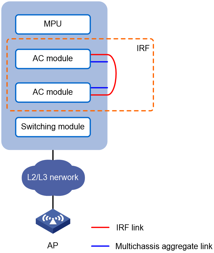
Figure 6 AC module IRF fabric hosted in different chassis
Procedure
In this example, the AC module IRF fabric is hosted in the same chassis.
Configuring the switch
1. Configure links for interfaces connected to the IRF network interfaces of the AC modules:
# Create Layer 2 aggregate interface Bridge-Aggregation 1 for AC 1 IRF connection.
<Switch> system-view
[Switch] interface bridge-aggregation 1
[Switch-Bridge-Aggregation1] quit
# Assign internal port Ten-GigabitEthernet 2/2/0/1 to aggregation group 1.
[Switch] interface ten-gigabitethernet 2/2/0/1
[Switch-Ten-GigabitEthernet2/2/0/1] port link-aggregation group 1
[Switch-Ten-GigabitEthernet2/2/0/1] quit
# Assign internal port Ten-GigabitEthernet 2/2/0/3 to aggregation group 1.
[Switch] interface ten-gigabitethernet 2/2/0/3
[Switch-Ten-GigabitEthernet2/2/0/3] port link-aggregation group 1
[Switch-Ten-GigabitEthernet2/2/0/3] quit
# Create Layer 2 aggregate interface Bridge-Aggregation 2 for AC 2 IRF connection.
[Switch] interface bridge-aggregation 2
[Switch-Bridge-Aggregation2] quit
# Assign internal port Ten-GigabitEthernet 2/5/0/1 to aggregation group 2.
[Switch] interface ten-gigabitethernet 2/5/0/1
[Switch-Ten-GigabitEthernet2/5/0/1] port link-aggregation group 2
[Switch-Ten-GigabitEthernet2/5/0/1] quit
# Assign internal port Ten-GigabitEthernet 2/5/0/3 to aggregation group 2.
[Switch]interface ten-gigabitethernet 2/5/0/3
[Switch-Ten-GigabitEthernet2/5/0/3] port link-aggregation group 2
[Switch-Ten-GigabitEthernet2/5/0/3] quit
# Create VLAN 400 and assign the aggregate interfaces to the VLAN. The VLAN will transmit IRF traffic.
[Switch] vlan 400
[Switch-vlan400] port bridge-aggregation 1
[Switch-vlan400] port bridge-aggregation 2
[Switch-vlan400] quit
# Disable the spanning tree feature on Bridge-Aggregation 1 and Bridge-Aggregation 2.
[Switch] interface bridge-aggregation 1
[Switch-Bridge-Aggregation1] undo stp enable
[Switch-Bridge-Aggregation1] quit
[Switch] interface bridge-aggregation 2
[Switch-Bridge-Aggregation2] undo stp enable
[Switch-Bridge-Aggregation2] quit
2. Configure links used for transmitting LACP MAD packets:
# Create Layer 2 aggregate interface Bridge-Aggregation 3, and configure the aggregation group of the aggregate interface to operate in dynamic mode.
[Switch] interface bridge-aggregation 3
[Switch-Bridge-Aggregation3] link-aggregation mode dynamic
[Switch-Bridge-Aggregation3] quit
# Assign internal port Ten-GigabitEthernet 2/2/0/2 to aggregation group 3.
[Switch] interface ten-gigabitethernet 2/2/0/2
[Switch-Ten-GigabitEthernet2/2/0/2] port link-aggregation group 3
[Switch-Ten-GigabitEthernet2/2/0/2] quit
# Assign internal port Ten-GigabitEthernet 2/2/0/4 to aggregation group 3.
[Switch] interface ten-gigabitethernet 2/2/0/4
[Switch-Ten-GigabitEthernet2/2/0/4] port link-aggregation group 3
[Switch-Ten-GigabitEthernet2/2/0/4] quit
# Assign internal port Ten-GigabitEthernet 2/5/0/2 to aggregation group 3.
[Switch] interface ten-gigabitethernet 2/5/0/2
[Switch-Ten-GigabitEthernet2/5/0/2] port link-aggregation group 3
[Switch-Ten-GigabitEthernet2/5/0/2] quit
# Assign internal port Ten-GigabitEthernet 2/5/0/4 to aggregation group 3.
[Switch] interface ten-gigabitethernet 2/5/0/4
[Switch-Ten-GigabitEthernet2/5/0/4] port link-aggregation group 3
[Switch-Ten-GigabitEthernet2/5/0/4] quit
3. Enable link-aggregation traffic redirection.
[Switch] link-aggregation lacp traffic-redirect-notification enable
Configuring AC 1
# Assign internal ports Ten-GigabitEthernet 1/0/1 and Ten-GigabitEthernet 1/0/3 to the IRF port.
<AC1> system-view
[AC1] irf-port 1
[AC1-irf-port1] port group interface ten-gigabitethernet 1/0/1
You must perform the following tasks for a successful IRF setup:
Save the configuration after completing IRF configuration.
Execute the \"irf-port-configuration active\" command to activate the IRF ports.
[AC1-irf-port1] port group interface ten-gigabitethernet 1/0/3
You must perform the following tasks for a successful IRF setup:
Save the configuration after completing IRF configuration.
Execute the \"irf-port-configuration active\" command to activate the IRF ports.
[AC1-irf-port1] quit
# Set the member priority to 2. AC 1 will be the master device.
[AC1] irf member 1 priority 2
# Save the configuration.
[AC1] save
The current configuration will be written to the device. Are you sure? [Y/N]:y
Please input the file name(*.cfg)[cfa0:/startup.cfg]
(To leave the existing filename unchanged, press the enter key):irf.cfg
Validating file. Please wait...
Saved the current configuration to mainboard device successfully.
# Activate the IRF port configuration.
[AC1] irf-port-configuration active
Configuring AC 2
# Change the IRF member ID to 2.
<AC2> system-view
[AC2] irf member 1 renumber 2
Renumbering the member ID may result in configuration change or loss. Continue?[
Y/N]:y
[AC2] quit
# Reboot AC 2 for the new member ID to take effect.
<AC2> reboot
Start to check configuration with next startup configuration file, please wait..
.......DONE!
Current configuration may be lost after the reboot, save current configuration?
[Y/N]:y
Please input the file name(*.cfg)[cfa0:/startup.cfg]
(To leave the existing filename unchanged, press the enter key):irf.cfg
cfa0:/startup.cfg exists, overwrite? [Y/N]:y
Validating file. Please wait...
Saved the current configuration to mainboard device successfully.
This command will reboot the device. Continue? [Y/N]:y
Now rebooting, please wait...
# Assign internal ports Ten-GigabitEthernet 2/0/1 and Ten-GigabitEthernet 2/0/3 to the IRF port.
<AC2> system-view
[AC2] irf-port 2
[AC2-irf-port2] port group interface ten-gigabitethernet 2/0/1
You must perform the following tasks for a successful IRF setup:
Save the configuration after completing IRF configuration.
Execute the \"irf-port-configuration active\" command to activate the IRF ports.
[AC2-irf-port2] port group interface ten-gigabitethernet 2/0/3
You must perform the following tasks for a successful IRF setup:
Save the configuration after completing IRF configuration.
Execute the \"irf-port-configuration active\" command to activate the IRF ports.
[AC2-irf-port2] quit
# Save the configuration.
[AC2] save
The current configuration will be written to the device. Are you sure? [Y/N]:y
Please input the file name(*.cfg)[cfa0:/ irf.cfg]
(To leave the existing filename unchanged, press the enter key):
Validating file. Please wait...
Saved the current configuration to mainboard device successfully.
# Activate the IRF port configuration.
[AC2] irf-port-configuration active
AC 1 and AC 2 perform master election. AC 2 fails the master election and reboots to form an IRF fabric with AC 1.
Configuring the IRF fabric
# Change the name of the IRF fabric to IRF.
<AC1> system-view
[AC1] system-name IRF
# Configure descriptions for AC 1 and AC 2.
[IRF] irf member 1 description AC 1
[IRF] irf member 2 description AC 2
# Delete the system-defined aggregate interface named Bridge-Aggregation 1. The member ports will automatically leave the aggregation group of Bridge-Aggregation 1.
[IRF] undo interface bridge-aggregation 1
# Create Layer 2 aggregate interface Bridge-Aggregation 3, and set the aggregation mode to dynamic mode.
[IRF] interface bridge-aggregation 3
[IRF-Bridge-Aggregation3] link-aggregation mode dynamic
# Enable LACP MAD on Bridge-Aggregation 3.
[IRF-Bridge-Aggregation3] mad enable
[IRF-Bridge-Aggregation3] quit
# Enable link-aggregation traffic redirection.
[IRF] link-aggregation lacp traffic-redirect-notification enable
# Assign internal port Ten-GigabitEthernet 1/0/2 to aggregation group 3.
[IRF] interface ten-gigabitethernet 1/0/2
[IRF-Ten-GigabitEthernet1/0/2] port link-aggregation group 3
[IRF-Ten-GigabitEthernet1/0/2] quit
# Assign internal port Ten-GigabitEthernet 1/0/4 to aggregation group 3.
[IRF] interface ten-gigabitethernet 1/0/4
[IRF-Ten-GigabitEthernet1/0/4] port link-aggregation group 3
[IRF-Ten-GigabitEthernet1/0/4] quit
# Assign internal port Ten-GigabitEthernet 2/0/2 to aggregation group 3.
[IRF] interface ten-gigabitethernet 2/0/2
[IRF-Ten-GigabitEthernet2/0/2] port link-aggregation group 3
[IRF-Ten-GigabitEthernet2/0/2] quit
# Assign internal port Ten-GigabitEthernet 2/0/4 to aggregation group 3.
[IRF] interface ten-gigabitethernet 2/0/4
[IRF-Ten-GigabitEthernet2/0/4] port link-aggregation group 3
[IRF-Ten-GigabitEthernet2/0/4] quit
Verifying the configuration
# Display IRF information. Verify that AC 1 is the master device.
[IRF] display irf
Member ID Role Priority CPU MAC Description
*+1 Master 2 50da-005b-8b98 AC 1
2 Standby 1 70f9-6d17-2e37 AC 2
--------------------------------------------------
The asterisk (*) indicates the master.
The plus sign (+) indicates the device through which you are logged in.
The right angle bracket (>) indicates the device's stack capability is disabled.
Bridge MAC of the IRF: 50da-005b-8b98
Auto upgrade : Enabled
MAC persistence : 6 min
Topo-domain ID : 0
Auto merge : Enabled
# Display IRF link information. Verify that the IRF network interfaces on both member devices are up.
[IRF] display irf link
Member ID Member Interfaces Status
1 XGE1/0/1(ctrl&data) Up
XGE1/0/3(ctrl&data) Up
2 XGE2/0/1(ctrl&data) Up
XGE2/0/3(ctrl&data) Up
# On the IRF fabric, display detailed information about aggregation groups. Verify that Ten-GigabitEthernet 1/0/2, Ten-GigabitEthernet 1/0/4, Ten-GigabitEthernet 2/0/2, and Ten-GigabitEthernet 2/0/4 are in aggregation group 3 and in Selected state.
[IRF] display link-aggregation verbose
Loadsharing Type: Shar -- Loadsharing, NonS -- Non-Loadsharing
Port Status: S -- Selected, U -- Unselected, I -- Individual
Flags: A -- LACP_Activity, B -- LACP_Timeout, C -- Aggregation,
D -- Synchronization, E -- Collecting, F -- Distributing,
G -- Defaulted, H -- Expired
Aggregate Interface: Bridge-Aggregation3
Aggregation Mode: Dynamic
Loadsharing Type: NonS
System ID: 0x8000, 50da-005b-8b98
Local:
Port Status Priority Oper-Key Flag
--------------------------------------------------------------------------------
XGE1/0/2 S 32768 1 {ACDEF}
XGE1/0/4 S 32768 1 {ACDEF}
XGE2/0/2 S 32768 1 {ACDEF}
XGE2/0/4 S 32768 1 {ACDEF}
Remote:
Actor Partner Priority Oper-Key SystemID Flag
--------------------------------------------------------------------------------
XGE1/0/2 1943 32768 3 0x8000, 741f-4a56-9890 {ACDEF}
XGE1/0/4 1944 32768 3 0x8000, 741f-4a56-9890 {ACDEF}
XGE2/0/2 2234 32768 3 0x8000, 741f-4a56-9890 {ACDEF}
XGE2/0/4 2235 32768 3 0x8000, 741f-4a56-9890 {ACDEF}
# On the switch, display detailed information about aggregation groups. Verify the link aggregation settings and verify that all member ports in the aggregation groups are in Selected state.
[Switch]display link-aggregation verbose
Loadsharing Type: Shar -- Loadsharing, NonS -- Non-Loadsharing
Port Status: S -- Selected, U -- Unselected, I -- Individual
Flags: A -- LACP_Activity, B -- LACP_Timeout, C -- Aggregation,
D -- Synchronization, E -- Collecting, F -- Distributing,
G -- Defaulted, H -- Expired
Aggregate Interface: Bridge-Aggregation1
Aggregation Mode: Static
Loadsharing Type: Shar
Port Status Priority Oper-Key
--------------------------------------------------------------------------------
XGE2/2/0/1 S 32768 1
XGE2/2/0/3 S 32768 1
Aggregate Interface: Bridge-Aggregation2
Aggregation Mode: Static
Loadsharing Type: Shar
Port Status Priority Oper-Key
--------------------------------------------------------------------------------
XGE2/5/0/1 S 32768 2
XGE2/5/0/3 S 32768 2
Aggregate Interface: Bridge-Aggregation3
Aggregation Mode: Dynamic
Loadsharing Type: Shar
System ID: 0x8000, 741f-4a56-9890
Local:
Port Status Priority Oper-Key Flag
--------------------------------------------------------------------------------
XGE2/2/0/2 S 32768 3 {ACDEF}
XGE2/2/0/4 S 32768 3 {ACDEF}
XGE2/5/0/2 S 32768 3 {ACDEF}
XGE2/5/0/4 S 32768 3 {ACDEF}
Remote:
Actor Partner Priority Oper-Key SystemID Flag
--------------------------------------------------------------------------------
XGE2/2/0/2 5 32768 1 0x8000, 50da-005b-8b98 {ACDEF}
XGE2/2/0/4 6 32768 1 0x8000, 50da-005b-8b98 {ACDEF}
XGE2/5/0/2 11 32768 1 0x8000, 50da-005b-8b98 {ACDEF}
XGE2/5/0/4 12 32768 1 0x8000, 50da-005b-8b98 {ACDEF}
FAQ
How many member devices can an AC IRF fabric contain?
An AC IRF fabric can contain a maximum of two member devices.
What are the requirements for the software version of member devices in an IRF fabric?
All IRF member devices must run the same software image version as the master. For software synchronization, make sure the software auto-update feature is enabled.
The software auto-update feature automatically synchronizes the current software images of the master to devices that are attempting to join the IRF fabric.
You must manually update the new device with the software images running on the IRF fabric if software auto-update is disabled.
What are the requirements for the bridge MAC addresses of member devices that will join the same IRF fabric?
Make sure each member device has a unique bridge MAC address. Member devices cannot join the same IRF fabric if they have the same bridge MAC address.
How do I make the APs associate with the active AC quickly after the AC IRF fabric recovers from a split?
Use the irf mac-address persistent always command to enable the IRF fabric to retain the bridge MAC address permanently even if the address owner has left the fabric.
Do I need to disable the spanning tree feature on the ports connected to IRF network interfaces on the intermediate devices?
Yes.
In what situations should I use intermediate devices to connect IRF member devices?
You can directly connect the IRF member devices or through switching devices as needed. There are no special scenarios that require intermediate switches.
What are the requirements for IRF topo-domain IDs?
To form an IRF fabric, all member devices must have the same topo-domain ID. Only devices that use the same topo-domain ID can join the same IRF fabric.
Are there any configuration restrictions and guidelines for an IRF fabric after the IRF fabric is set up?
Follow these restrictions and guidelines:
· You cannot use the shutdown command on the IRF standby device to shut down an IRF network interface if the interface is the only control channel available on the device. To shut down the IRF link in this situation, shut down the IRF network interface on the master device.
· To remove a network interface from an IRF port, you must first shut down the IRF network interface.
· On the Layer 2 intermediate devices, do not configure per-packet load sharing on a Layer 2 aggregate interface connected to multiple member devices of the IRF fabric.
Related documentation
· Network Connectivity Configuration Guide in H3C Access Controllers Configuration Guides
· Network Connectivity Command Reference in H3C Access Controllers Command References
· IRF Configuration Guide in H3C Access Controllers Configuration Guides
· IRF Command Reference in H3C Access Controllers Command References
· H3C Access Controllers Comware 7 IRF Setup with Members Directly Connected Configuration Examples in H3C Access Controllers Comware 7 Configuration Examples
· H3C Access Controllers Comware 7 IRF Setup with Members Not Directly Connected Configuration Examples in H3C Access Controllers Comware 7 Configuration Examples
· H3C Access Controller Modules Comware 7 IRF Setup with Members in One Chassis Configuration Examples in H3C Access Controllers Comware 7 Configuration Examples
· H3C Access Controller Modules Comware 7 IRF Setup with Members in Different Chassis Configuration Examples in H3C Access Controllers Comware 7 Configuration Examples
