- Table of Contents
- Related Documents
-
| Title | Size | Download |
|---|---|---|
| 03-Reth interface and redundancy group configuration | 262.36 KB |
Restrictions: Hardware compatibility with Reth interface
Restrictions and guidelines: Reth interface configuration
Restrictions and guidelines: Reth interface configuration
Configuring basic parameters for a Reth interface
Enabling fast traffic switchover on a Reth interface
Configuring a Reth subinterface
Restoring default settings for a Reth interface or subinterface
Displaying and maintaining Reth interfaces
Operating mechanism of a redundancy group
Restrictions: Hardware compatibility with redundancy group
Redundancy group configuration tasks at a glance
Configuring a redundancy group node
Assigning physical Ethernet interfaces to a redundancy group
Assigning Reth interfaces to a redundancy group
Configuring the switchover timers
Performing a manual switchover to the low-priority node
Performing a manual switchover back to the high-priority node
Enabling SNMP notifications for redundancy groups
Displaying and maintaining redundancy groups
Redundancy group configuration examples
Example: Configuring a redundancy group with Layer 3 interface members
Example: Configuring a redundancy group with Reth interface members
Configuring Reth interfaces
About Reth interfaces
A redundant Ethernet (Reth) interface is a virtual Layer 3 interface that uses two member interfaces to ensure link availability. One member interface is active and the other is inactive. When the active interface fails, the inactive interface becomes active. The member interface switchover does not interrupt traffic.
Operating mechanism
A member interface of a Reth interface can be in either of the following states:
· Active—The interface can forward packets. A Reth interface can have only one active member interface.
· Inactive—The interface cannot forward packets.
A Reth interface determines the state of its member interfaces by using the following rules:
· When the member interfaces are physically up, the member interface with the higher priority is active. The other member interface is inactive. The priority of an interface is user configurable.
· When the member interfaces are physically down, both interfaces are inactive.
· When the active member interface goes down physically, the inactive interface automatically becomes active to forward packets.
If the Reth interface is added to a redundancy group, the member interface states are determined by the redundancy group. For more information, see "Configuring redundancy groups."
The switchover between the Reth member interfaces is not visible to the network and does not cause network topology changes. For the upstream and downstream devices, they are connected to the Reth interface and learn only the MAC address of the Reth interface.
Application scenario
The Reth interface feature is typically used with the redundancy group feature. For more information, see "Configuring redundancy groups."
Reth subinterfaces
To transmit and receive VLAN-tagged packets on a Reth interface, you can create subinterfaces for the Reth interface. A Reth subinterface is a Layer 3 logical interface and can be assigned an IP address. Packets from different VLANs can be forwarded by different Reth subinterfaces, which improves the interface efficiency and networking flexibility. For more information about VLAN-tagged packet processing on a Reth subinterface, see VLAN termination in Layer 2—LAN Switching Configuration Guide.
Restrictions: Hardware compatibility with Reth interface
|
F1000 series |
Models |
Reth interface compatibility |
|
F1000-X-G5 series |
F1000-A-G5, F1000-C-G5, F1000-C-G5-LI, F1000-E-G5, F1000-H-G5, F1000-S-G5 |
Yes |
|
F1000-X-G3 series |
F1000-A-G3, F1000-C-G3, F1000-E-G3, F1000-S-G3 |
Yes |
|
F1000-X-G2 series |
F1000-A-G2, F1000-C-G2, F1000-E-G2, F1000-S-G2 |
Yes |
|
F1000-9X0-AI series |
F1000-9390-AI, F1000-9385-AI, F1000-9380-AI, F1000-9370-AI, F1000-9360-AI, F1000-9350-AI, F1000-9330-AI, F1000-9320-AI, F1000-990-AI, F1000-980-AI, F1000-970-AI, F1000-960-AI, F1000-950-AI, F1000-930-AI, F1000-920-AI |
Yes |
|
F1000-910-AI, F1000-905-AI |
No |
|
|
F1000-C83X0 series |
F1000-C8395, F1000-C8390, F1000-C8385, F1000-C8380, F1000-C8370, F1000-C8360, F1000-C8350, F1000-C8330 |
Yes |
|
F1000-C81X0 series |
F1000-C8180, F1000-C8170, F1000-C8160 |
Yes |
|
F1000-C8150, F1000-C8130, F1000-C8120, F1000-C8110 |
No |
|
|
F1000-7X0-HI series |
F1000-770-HI, F1000-750-HI, F1000-740-HI, F1000-730-HI |
Yes |
|
F1000-720-HI, F1000-710-HI |
No |
|
|
F1000-C-X series |
F1000-C-EI, F1000-C-HI, F1000-C-XI, F1000-E-XI |
Yes |
|
F1000-V series |
F1000-E-VG |
Yes |
|
F1000-S-VG |
No |
|
|
SecBlade IV |
LSPM6FWD8, LSQM2FWDSC8 |
Yes |
|
F100 series |
Models |
Reth interface compatibility |
|
F100-X-G5 series |
F100-A-G5, F100-E-G5 |
Yes |
|
F100-C-G5, F100-M-G5, F100-S-G5 |
No |
|
|
F100-X-G3 series |
F100-A-G3, F100-E-G3 |
Yes |
|
F100-C-G3, F100-M-G3, F100-S-G3 |
No |
|
|
F100-X-G2 series |
F100-A-G2, F100-E-G2 |
Yes |
|
F100-C-G2, F100-M-G2, F100-S-G2 |
No |
|
|
F100-WiNet series |
F100-A91-WiNet, F100-A81-WiNet, F100-A80-WiNet |
Yes |
|
F100-C80-WiNet, F100-C60-WiNet, F100-C50-WiNet, F100-S80-WiNet |
No |
|
|
F100-C-A series |
F100-C-A6, F100-C-A5, F100-C-A3, F100-C-A2, F100-C-A1, F100-C-A6-WL, F100-C-A5-W, F100-C-A3-W |
No |
|
F100-X-XI series |
F100-A-EI, F100-A-HI, F100-A-SI, F100-E-EI |
Yes |
|
F100-C-EI, F100-C-HI, F100-C-XI, F100-S-HI, F100-S-XI |
No |
Restrictions and guidelines: Reth interface configuration
During master/subordinate switchover in an IRF fabric, do not delete the aggregate interface from the Reth interface.
Configuring a Reth interface
Restrictions and guidelines: Reth interface configuration
Supported member interface types
A Reth interface can use the following interfaces and their subinterfaces as member interfaces:
· Layer 3 Ethernet interfaces.
|
|
IMPORTANT: If a Layer 3 Ethernet interface is marked as a bypass interface on the panel or has the bypass feature enabled, do not use that interface as a member interface of a Reth interface. If you do so, communication errors will occur. For more information about the bypass feature, see "Configuring bridge forwarding." |
· Layer 3 aggregate interfaces.
Member interface configuration
When you configure a Reth interface, follow these restrictions and guidelines:
· You can assign a maximum of two member interfaces to a Reth interface. The member interfaces must have different priorities.
· You cannot assign member interfaces to a Reth subinterface.
· You cannot assign subinterfaces or interfaces that have subinterfaces to a Reth interface if the Reth interface has Reth subinterfaces.
· You can assign an interface or subinterface to only one Reth interface.
· As a best practice, assign interfaces of the same type and speed to a Reth interface.
· If both member interfaces of a Reth interface are subinterfaces, make sure they are on different main interfaces and terminate the same VLAN ID. For more information about VLAN termination, see Layer 2—LAN Switching Configuration Guide.
· Do not specify a Reth interface as the outgoing interface in IPv6 static neighbor entries if its member interfaces contain subinterfaces. For more information about IPv6 static neighbor entries, see Layer 3—IP Services Configuration Guide.
· Settings made on the member interfaces of a Reth interface will not take effect until they are removed from the Reth interface.
Member interface deletion
Before you delete a Reth interface, make sure all its member interfaces have been removed.
Configuring basic parameters for a Reth interface
1. Enter system view.
system-view
2. Create a Reth interface and enter its view.
interface reth interface-number
By default, no Reth interfaces exist.
3. Assign a member interface to the Reth interface.
member interface interface-type interface-number priority priority
By default, a Reth interface does not have member interfaces.
4. (Optional.) Configure the expected bandwidth for the Reth interface.
bandwidth bandwidth-value
By default, the expected bandwidth is 10000 kbps.
The expected bandwidth is an informational parameter used only by higher-layer protocols for calculation. You cannot adjust the actual bandwidth of an interface by using this command.
5. (Optional.) Configure the description of the Reth interface.
description text
The default description of a Reth interface is interface-name Interface (for example, Reth1 Interface).
6. (Optional.) Set the MTU of the Reth interface.
mtu size
By default, the MTU of a Reth interface is 1500 bytes.
7. (Optional.) Assign a MAC address to the Reth interface.
mac-address mac-address
By default, Reth interfaces use the bridge MAC address of the device.
Reth interfaces use the same default MAC address. To avoid communication errors, manually assign unique MAC addresses to the Reth interfaces.
8. Bring up the Reth interface.
undo shutdown
By default, a Reth interface is not manually shut down.
Setting the parameters for retransmitting advertisement messages after a Reth member interface switchover
About this task
After you configure the parameters for retransmitting advertisement messages, a Reth interface performs the following operations when a Reth member interface switchover occurs on it:
1. Sends advertisement messages (including gratuitous ARP messages and NA messages) to neighbors immediately.
2. Retransmits the advertisement messages according to the number of retransmissions and the retransmission interval you have configured.
Restrictions and guidelines
If a Reth interface has subinterfaces, the subinterfaces also send advertisement messages upon a Reth member interface switchover. To save CPU resources, the parameters for retransmitting advertisement messages take effect only on Reth interfaces. Reth subinterfaces are not controlled by these parameters.
Procedure
1. Enter system view.
system-view
2. Set the parameters for retransmitting advertisement messages to neighbors after a Reth member interface switchover.
reth advertise retransmit times interval seconds
By default, after a Reth member interface switchover, a Reth interface retransmits advertisement messages to neighbors five times at an interval of 1 second.
Enabling fast traffic switchover on a Reth interface
About fast traffic switchover
|
|
IMPORTANT: This feature introduces low possibility of forwarding traffic on the inactive member interface while the system is operating correctly. Make sure you understand this impact on your services when you use this feature. |
This feature enables faster traffic switchover between Reth member interfaces than the standard switchover mechanism of Reth when the master device is powered off or reboots unexpectedly.
This feature implements fast switchover by allowing the inactive member interface to forward packets. In rare cases, the neighbor device might learn MAC address entries on the link connected to the inactive interface and sends traffic to the inactive interface.
Hardware and feature compatibility
|
F1000 series |
Models |
Feature compatibility |
|
F1000-X-G5 series |
F1000-A-G5, F1000-C-G5, F1000-C-G5-LI, F1000-E-G5, F1000-H-G5, F1000-S-G5 |
Yes |
|
F1000-X-G3 series |
F1000-A-G3, F1000-C-G3, F1000-E-G3, F1000-S-G3 |
Yes |
|
F1000-X-G2 series |
F1000-A-G2, F1000-C-G2, F1000-E-G2, F1000-S-G2 |
Yes |
|
F1000-9X0-AI series |
F1000-9390-AI, F1000-9385-AI, F1000-9380-AI, F1000-9370-AI, F1000-9360-AI, F1000-9350-AI, F1000-990-AI, F1000-980-AI, F1000-970-AI, F1000-960-AI, F1000-950-AI, F1000-930-AI, F1000-920-AI |
Yes |
|
F1000-9330-AI, F1000-9320-AI, F1000-910-AI, F1000-905-AI |
No |
|
|
F1000-C83X0 series |
F1000-C8395, F1000-C8390, F1000-C8385, F1000-C8380, F1000-C8370, F1000-C8360, F1000-C8350 |
Yes |
|
F1000-C8330 |
No |
|
|
F1000-C81X0 series |
F1000-C8180, F1000-C8170, F1000-C8160 |
Yes |
|
F1000-C8150, F1000-C8130, F1000-C8120, F1000-C8110 |
No |
|
|
F1000-7X0-HI series |
F1000-770-HI, F1000-750-HI, F1000-740-HI |
Yes |
|
F1000-730-HI, F1000-720-HI, F1000-710-HI |
No |
|
|
F1000-C-X series |
F1000-C-EI, F1000-C-HI, F1000-C-XI, F1000-E-XI |
Yes |
|
F1000-V series |
F1000-E-VG |
Yes |
|
F1000-S-VG |
No |
|
|
SecBlade IV |
LSPM6FWD8, LSQM2FWDSC8 |
Yes |
|
F100 series |
Models |
Feature compatibility |
|
F100-X-G5 series |
F100-A-G5, F100-C-G5, F100-M-G5, F100-S-G5 |
No |
|
F100-E-G5 |
Yes |
|
|
F100-X-G3 series |
F100-A-G3, F100-E-G3 |
Yes |
|
F100-C-G3, F100-M-G3, F100-S-G3 |
No |
|
|
F100-X-G2 series |
F100-A-G2, F100-E-G2 |
Yes |
|
F100-C-G2, F100-M-G2, F100-S-G2 |
No |
|
|
F100-WiNet series |
F100-A91-WiNet, F100-A80-WiNet |
Yes |
|
F100-A81-WiNet, F100-C80-WiNet, F100-C60-WiNet, F100-C50-WiNet, F100-S80-WiNet |
No |
|
|
F100-C-A series |
F100-C-A6, F100-C-A5, F100-C-A3, F100-C-A2, F100-C-A1, F100-C-A6-WL, F100-C-A5-W, F100-C-A3-W |
No |
|
F100-X-XI series |
F100-A-EI, F100-A-HI, F100-A-SI, F100-E-EI |
Yes |
|
F100-C-EI, F100-C-HI, F100-C-XI, F100-S-HI, F100-S-XI |
No |
Restrictions and guidelines
For this feature to take effect and operate effectively, follow these restrictions and guidelines:
· Make sure the Reth member interfaces are physical interfaces.
· Enable fast switchover on both the Reth interface for uplink traffic and the Reth interface for downlink traffic.
· Assign the downlink and uplink Reth interfaces to a redundancy group.
· Make sure the high-priority Reth member interfaces are on the master device (high-priority redundancy group node).
· To minimize the chance of receiving traffic on the inactive interface, use the arp timer aging command on the neighbor device to shorten the ARP entry aging timer.
Procedure
1. Enter system view.
system-view
2. Enter Reth interface view.
interface reth interface-number
3. Enable fast traffic switchover.
fast-switch enable
By default, fast traffic switchover is disabled.
Configuring a Reth subinterface
About this task
You can create Reth subinterfaces and configure VLAN termination on the Reth subinterfaces to process VLAN-tagged packets.
Restrictions and guidelines
When you configure a Reth subinterface, follow these restrictions and guidelines:
· To create a Reth subinterface, create the Reth interface first.
· You cannot create subinterfaces for a Reth interface in any of the following situations:
¡ The members of the Reth interface are Layer 3 Ethernet subinterfaces or Layer 3 aggregate subinterfaces.
¡ A minimum of one subinterface is created on the member interfaces of the Reth interface.
Procedure
1. Enter system view.
system-view
2. Create a Reth subinterface and enter its view.
interface reth interface-number.subnumber
By default, no Reth subinterfaces exist.
If the specified Reth subinterface already exists, this command enters the view of the Reth subinterface.
3. (Optional.) Configure the expected bandwidth for the Reth subinterface.
bandwidth bandwidth-value
By default, the expected bandwidth is 10000 kbps.
4. (Optional.) Configure a description for the Reth subinterface.
description text
The default description of a Reth subinterface is interface-name Interface (for example, Reth1.1 Interface).
5. (Optional.) Set the MTU of the Reth subinterface.
mtu size
By default, the MTU of a Reth subinterface is 1500 bytes.
6. Return to system view.
quit
7. Enter Reth interface view.
interface reth interface-number
8. Enable subinterface rate statistics collection on the Reth interface.
sub-interface rate-statistic
By default, subinterface rate statistics collection is disabled on a Reth interface.
After you execute this command, the device periodically refreshes subinterface rate statistics for the Reth interface. The statistics is displayed in the Last 300 seconds input rate and Last 300 seconds output rate fields of the command output from the display interface reth command.
9. Return to system view.
quit
10. Enter Reth subinterface view.
interface reth interface-number.subnumber
11. Bring up the Reth subinterface.
undo shutdown
By default, a Reth subinterface is not manually shut down.
Restoring default settings for a Reth interface or subinterface
Restrictions and guidelines
|
|
CAUTION: The default command might interrupt ongoing network services. Make sure you are fully aware of the impacts of this command when you execute it on a live network. |
This command might fail to restore the default settings for some commands for reasons such as command dependencies and system restrictions.
To resolve this issue:
1. Use the display this command in interface view to identify these commands.
2. Use their undo forms or follow the command reference to restore their default settings.
3. If the restoration attempt still fails, follow the error message instructions to resolve the issue.
Procedure
1. Enter system view.
system-view
2. Enter a Reth interface or subinterface view.
interface reth { interface-number | interface-number.subnumber }
3. Restore the default settings for the Reth interface.
default
Displaying and maintaining Reth interfaces
Execute display commands in any view and reset commands in user view.
|
Task |
Command |
|
Display Reth interface traffic statistics. |
display counters { inbound | outbound } interface [ reth [ interface-number ] ] |
|
Display traffic rate statistics for Reth interfaces in up state during the most recent statistics polling interval. |
display counters rate { inbound | outbound } interface [ reth [ interface-number ] ] |
|
Display Reth interface or subinterface information. |
display interface [ reth [ interface-number | interface-number.subnumber ] ] [ brief [ description | down ] ] |
|
Display information about the member interfaces of a Reth interface. |
display reth interface interface-type interface-number |
|
Clear statistics for Reth interfaces. |
reset counters interface [ reth [ interface-number ] ] |
Configuring redundancy groups
About redundancy groups
A redundancy group works on IRF fabrics. It allows traffic to enter and leave an IRF fabric through the same member device.
Operating mechanism of a redundancy group
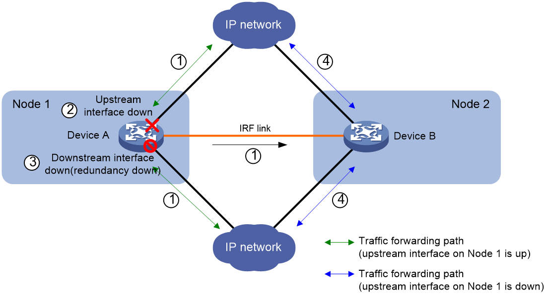
As shown in Figure 1, a redundancy group has two redundancy group nodes. Each node is bound to an IRF member device.
A redundancy group node is a collection of objects on its bound IRF member device. The objects include member interfaces of Reth interfaces and individual physical Ethernet interfaces. The state of the objects is consistent with the state of the node.
In a redundancy group, one node is in primary state, and the other node is in secondary state. Only the primary node forwards traffic. When the primary node fails, the redundancy group switches over to the secondary node. This mechanism ensures path symmetry for traffic.
As shown in Figure 1, a redundancy group performs a switchover as follows:
1. When both IRF member devices are operating correctly, the redundancy group forwards traffic through Node 1 (Device A) and backs up services and data (such as NAT) to Node 2 (Device B).
2. When the upstream interface on Device A fails, the redundancy group shuts down the downstream interface on Device A and switches traffic over to Device B.
Figure 1 Redundancy group operating mechanism
Redundancy group node states
A redundancy group node can act as the primary or secondary node. Only the primary node can forward traffic.
When both nodes are operating correctly, the primary node is selected in the following order:
1. The node with higher node priority.
2. The node with smaller ID if the two nodes have the same priority.
When the primary node fails, the secondary node takes over the primary role to forward traffic. For more information about the state monitoring and switchover mechanisms, see "Redundancy group switchover."
Redundancy group members
Application scenarios of redundancy group members
Redundancy group members can be physical Ethernet interfaces and Reth interfaces that are located on the IRF member devices bound to the group's nodes.
You can assign physical Ethernet interfaces or Reth interfaces to a redundancy group for symmetric traffic forwarding, as shown in Table 1.
Table 1 Application scenarios of physical Ethernet interfaces and Reth interfaces
|
Member type |
Application scenarios |
Supported interfaces |
|
Physical Ethernet interfaces |
Dynamic routing protocols run between the IRF fabric and its upstream and downstream devices. |
Layer 2 Ethernet interfaces. Later 3 Ethernet interfaces. |
|
Reth interfaces |
No dynamic routing protocol runs between the IRF fabric and its upstream and downstream devices. |
A Reth interface can use the following interfaces and their subinterfaces as member interfaces: · Layer 3 Ethernet interfaces. · Layer 3 aggregate interfaces. |
Using physical Ethernet interfaces in a redundancy group
You assign physical Ethernet interfaces to a redundancy group by binding them to their respective redundancy group nodes.
For symmetric traffic switchover, you must bind a minimum of one downlink interface and a minimum of one uplink interface with each node of the redundancy group.
The state of the member physical Ethernet interfaces changes with the state of the redundancy group nodes. Only the member interfaces on the primary node can forward traffic.
As shown in Figure 2, Interface A1 and Interface A2 are on Node 1, and Interface B1 and Interface B2 are on Node 2. When Node 1 is in primary state, Interface A1 and Interface A2 are up to forward traffic, while Interface B1 and Interface B2 do not forward traffic.
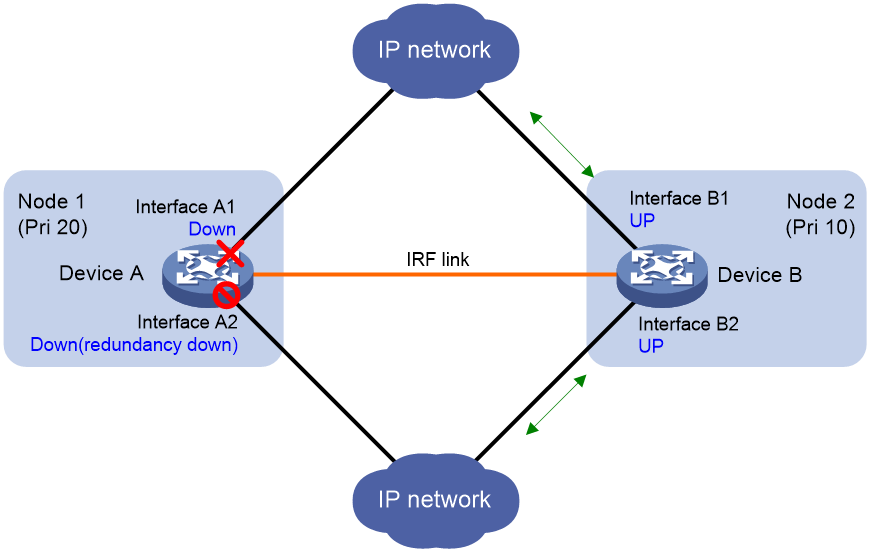
When Interface A1 goes down, the Reth module places Node 1 in secondary state. Node 2 changes to the primary state, and Interface B1 and Interface B2 take over to forward traffic, as shown in Figure 3.
Figure 2 States of the member interfaces when both nodes are operating correctly
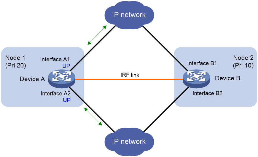
Figure 3 States of the member interfaces after a switchover
Using Reth interfaces in a redundancy group
To use Reth interfaces for symmetric forwarding, you must assign two Reth interfaces to a redundancy group: one for uplink traffic and the other for downlink traffic. The Reth interfaces must meet the following requirements:
· The Reth interface for uplink traffic contains one uplink port on each redundancy group node.
· The Reth interface for downlink traffic contains one downlink port on each redundancy group node.
· The high-priority member of each Reth interface belongs to the high-priority node.
The state of each Reth interface's members depends on the state of the redundancy group nodes.
· When the high-priority node is in primary state, the high-priority member is active.
· When the low-priority node is in primary state, the low-priority member is active.
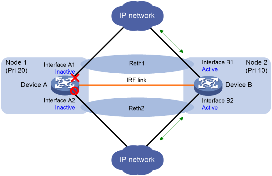
As shown in Figure 4, redundancy group 1 contains Reth 1 for uplink traffic and Reth 2 for downlink traffic. Reth 1 contains Interface A1 (on Node 1) and Interface B1 (on Node 2). Reth 2 contains Interface A2 (on Node 1) and Interface B2 (on Node 2).
When Node 1 is in primary state, Interface A1 in Reth 1 and Interface A2 in Reth 2 are active to forward uplink and downlink traffic, respectively.
When Interface A1 fails, the Reth module places Node 1 in secondary state and shuts down Interface A2, as shown in Figure 5. Node 2 changes to the primary state, and Interface B1 and Interface B2 become active to forward uplink and downlink traffic.
Figure 4 States of each Reth interface's members when both nodes are operating correctly
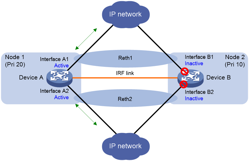
Figure 5 States of each Reth interface's members after a switchover
Redundancy group switchover
Switchover types
Redundancy group switchovers include automatic switchovers and manual switchovers.
Automatic switchover timers
Timers for automatic switchovers include the hold-down timer and the preemption delay timer.
· Hold-down timer—The hold-down timer specifies the minimum interval between two switchovers to prevent frequent switchovers. The timer starts when a switchover is finished. The redundancy group can perform the next switchover only after the hold-down timer expires.
· Preemption delay timer—The preemption delay timer specifies the delay for a switchover back to the high-priority node. The preemption delay timer starts when the switchover is triggered. The redundancy group performs the switchover only after the timer expires. The delay allows the system to process events (such as interface state changes) required for the switchover.
Automatic switchover
A redundancy group cooperates with the Track module to monitor link and interface status for automatic switchovers.
A redundancy group node has a weight of 255 (not configurable). Each redundancy group node is associated with one or multiple track entries that have a user-configurable weight decrement rate. When the state of a track entry changes, the weight of the associated node is reduced or increased, as follows:
· When the track entry changes to the NotReady or Negative state, the node weight is reduced by the weight decrement rate of the track entry.
· When the track entry changes to the Positive state, the node weight is increased by the weight decrement rate of the track entry.
When the node weight decreases to 0 or a lower value, a switchover request is triggered.
· Switchover to the low-priority node occurs when the hold-down timer expires.
· Switchover to the high-priority node occurs when the preemption delay timer expires.
Manual switchover
You can issue a manual switchover request in one of the following situations:
· An automatic switchover to the high-priority node cannot be performed when no tracked interfaces are excluded from the shutdown action by the Reth module.
· Switchovers are required when both redundancy group nodes operate correctly. For example, component replacement is required on the high-priority node.
Automatic switchover to the high-priority node is not allowed if the preemption delay timer is set to 0, even when both nodes are operating correctly. You can perform only manual switchover.
Restrictions: Hardware compatibility with redundancy group
|
F1000 series |
Models |
Redundancy group compatibility |
|
F1000-X-G5 series |
F1000-A-G5, F1000-C-G5, F1000-C-G5-LI, F1000-E-G5, F1000-H-G5, F1000-S-G5 |
Yes |
|
F1000-X-G3 series |
F1000-A-G3, F1000-C-G3, F1000-E-G3, F1000-S-G3 |
Yes |
|
F1000-X-G2 series |
F1000-A-G2, F1000-C-G2, F1000-E-G2, F1000-S-G2 |
Yes |
|
F1000-9X0-AI series |
F1000-9390-AI, F1000-9385-AI, F1000-9380-AI, F1000-9370-AI, F1000-9360-AI, F1000-9350-AI, F1000-9330-AI, F1000-9320-AI, F1000-990-AI, F1000-980-AI, F1000-970-AI, F1000-960-AI, F1000-950-AI, F1000-930-AI, F1000-920-AI |
Yes |
|
F1000-910-AI, F1000-905-AI |
No |
|
|
F1000-C83X0 series |
F1000-C8395, F1000-C8390, F1000-C8385, F1000-C8380, F1000-C8370, F1000-C8360, F1000-C8350, F1000-C8330 |
Yes |
|
F1000-C81X0 series |
F1000-C8180, F1000-C8170, F1000-C8160 |
Yes |
|
F1000-C8150, F1000-C8130, F1000-C8120, F1000-C8110 |
No |
|
|
F1000-7X0-HI series |
F1000-770-HI, F1000-750-HI, F1000-740-HI, F1000-730-HI |
Yes |
|
F1000-720-HI, F1000-710-HI |
No |
|
|
F1000-C-X series |
F1000-C-EI, F1000-C-HI, F1000-C-XI, F1000-E-XI |
Yes |
|
F1000-V series |
F1000-E-VG |
Yes |
|
F1000-S-VG |
No |
|
|
SecBlade IV |
LSPM6FWD8, LSQM2FWDSC8 |
Yes |
|
F100 series |
Models |
Redundancy group compatibility |
|
F100-X-G5 series |
F100-A-G5, F100-E-G5 |
Yes |
|
F100-C-G5, F100-M-G5, F100-S-G5 |
No |
|
|
F100-X-G3 series |
F100-A-G3, F100-E-G3 |
Yes |
|
F100-C-G3, F100-M-G3, F100-S-G3 |
No |
|
|
F100-X-G2 series |
F100-A-G2, F100-E-G2 |
Yes |
|
F100-C-G2, F100-M-G2, F100-S-G2 |
No |
|
|
F100-WiNet series |
F100-A91-WiNet, F100-A81-WiNet, F100-A80-WiNet |
Yes |
|
F100-C80-WiNet, F100-C60-WiNet, F100-C50-WiNet, F100-S80-WiNet |
No |
|
|
F100-C-A series |
F100-C-A6, F100-C-A5, F100-C-A3, F100-C-A2, F100-C-A1, F100-C-A6-WL, F100-C-A5-W, F100-C-A3-W |
No |
|
F100-X-XI series |
F100-A-EI, F100-A-HI, F100-A-SI, F100-E-EI |
Yes |
|
F100-C-EI, F100-C-HI, F100-C-XI, F100-S-HI, F100-S-XI |
No |
Redundancy group configuration tasks at a glance
To configure a redundancy group, perform the following tasks:
1. Creating a redundancy group
2. Configuring a redundancy group node
3. Assigning members to the redundancy group
¡ Assigning physical Ethernet interfaces to a redundancy group
This task is applicable to the network scenario where a dynamic routing protocol runs between the IRF fabric and its upstream and downstream devices.
¡ Assigning Reth interfaces to a redundancy group
This task is applicable to the network scenario where no dynamic routing protocol runs between the IRF fabric and its upstream and downstream devices.
4. Configuring the switchover timers
5. (Optional.) Performing a manual switchover
6. (Optional.) Performing a manual switchover back to the high-priority node
7. (Optional.) Enabling SNMP notifications for redundancy groups
Creating a redundancy group
Restrictions and guidelines
Before you delete a redundancy group, you must remove all its Reth interfaces and redundancy group nodes.
Procedure
1. Enter system view.
system-view
2. Create a redundancy group and enter its view.
redundancy group group-name
By default, no redundancy groups exist.
Configuring a redundancy group node
Restrictions and guidelines
You can configure a maximum of two nodes for a redundancy group. Nodes in different redundancy groups can use the same ID.
You can bind a redundancy group node to one IRF member device. An IRF member device cannot be bound to multiple redundancy group nodes. You cannot change the binding for a node if it has member interfaces or is associated with track entries.
When you associate a track entry with a redundancy group node, follow these restrictions and guidelines:
· You cannot associate a track entry with both nodes in a redundancy group.
· For correct interface state recovery, you must exclude a tracked interface from the shutdown action by the Reth module if the interface has one of the following roles:
¡ Member interface in the redundancy group.
¡ Member of a Reth interface in the redundancy group.
· On the high-priority node, do not exclude a subinterface from the shutdown action by the Reth module if its main interface has one of the following roles:
¡ Member interface of the redundancy group.
¡ Member of a Reth interface in the redundancy group.
When the Reth module shuts down the main interface, the subinterface is also shut down. The shutdown subinterface cannot recover automatically to trigger an automatic switchover.
Prerequisites
Before you associate a track entry with a redundancy group, you must configure the track entry. For more information about configuring track entries, see Network Management and Monitoring Configuration Guide.
Procedure
1. Enter system view.
system-view
2. Enter redundancy group view.
redundancy group group-name
3. Create a redundancy group node and enter its view.
node node-id
By default, no redundancy group nodes exist.
4. Set the priority of the redundancy group node.
priority priority
By default, the priority of a redundancy group node is 1.
5. Bind the redundancy group node with an IRF member device.
bind slot slot-number
By default, a node is not bound with an IRF member device.
6. Associate an existing track entry with the redundancy group node.
track track-entry-number [ reduced weight-reduced ] [ interface interface-type interface-number ]
By default, a node is not associated with track entries.
Assigning physical Ethernet interfaces to a redundancy group
Restrictions and guidelines
For symmetric traffic switchover, you must bind a minimum of one uplink interface and a minimum of one downlink interface with each node of the redundancy group.
You can bind a physical Ethernet interface with only one redundancy group node.
You cannot bind a member of a Reth interface with a redundancy group node.
Procedure
1. Enter system view.
system-view
2. Enter redundancy group view.
redundancy group group-name
3. Enter redundancy group node view.
node node-id
4. Bind a physical Ethernet interface with the redundancy group node.
node-member interface interface-type interface-number
By default, a physical Ethernet interface is not bound with a redundancy group node.
Assigning Reth interfaces to a redundancy group
Restrictions and guidelines
To use Reth interfaces for symmetric forwarding, you must assign two Reth interfaces to a redundancy group: one for uplink traffic and the other for downlink traffic. The Reth interfaces must meet the following requirements:
· The Reth interface for uplink traffic contains one uplink port on each redundancy group node.
· The Reth interface for downlink traffic contains one downlink port on each redundancy group node.
· The high-priority member of each Reth interface belongs to the high-priority node.
Procedure
1. Enter system view.
system-view
2. Create a Reth interface and enter its view.
interface reth interface-number
3. Assign a member interface to the Reth interface.
member interface interface-type interface-number priority priority
By default, a Reth interface does not have member interfaces.
Repeat this step to assign two member interfaces to the Reth interface. Assign a higher priority for the priority argument to the member interface on the high-priority redundancy node.
4. Return to system view.
quit
5. Enter redundancy group view.
redundancy group group-name
6. Assign the Reth interface to the redundancy group.
member interface reth interface-number [ quick-fallback ]
By default, a redundancy group does not contain Reth interfaces.
Configuring the switchover timers
1. Enter system view.
system-view
2. Enter redundancy group view.
redundancy group group-name
3. Set the hold-down timer for the redundancy group.
hold-down-interval second
By default, the hold-down timer is 1 second.
4. Set the preemption delay timer for the redundancy group.
preempt-delay seconds sec
By default, the preemption delay timer is 1 minute (60 seconds).
If you set this timer to 0 seconds, automatic switchover to the high-priority node is disabled. You can perform only manual switchover.
Performing a manual switchover to the low-priority node
1. Enter system view.
system-view
2. Enter redundancy group view.
redundancy group group-name
3. Request a switchover to the low-priority node.
switchover request
Performing a manual switchover back to the high-priority node
1. Enter system view.
system-view
2. Enter redundancy group view.
redundancy group group-name
3. Request a switchover back to the high-priority node.
switchover reset
Enabling SNMP notifications for redundancy groups
About this task
This feature enables SNMP notifications for the following events:
· A manual switchover is performed.
· An interface goes down.
· A faulty interface is recovered.
To send the event notifications to an NMS, you must also configure SNMP as described in Network Management and Monitoring Configuration Guide.
Procedure
1. Enter system view.
system-view
2. Enable SNMP notifications for redundancy groups.
snmp-agent trap enable rddc
By default, SNMP notifications are enabled for redundancy groups.
Displaying and maintaining redundancy groups
Execute display commands in any view.
|
Task |
Command |
|
Display redundancy group information. |
display redundancy group [ group-name ] |
Redundancy group configuration examples
Example: Configuring a redundancy group with Layer 3 interface members
Network configuration
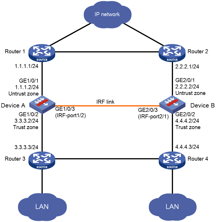
As shown in Figure 6, Device A (member ID 1) and Device B (member ID 2) form an IRF fabric.
Configure a redundancy group on the IRF fabric to ensure that traffic is forwarded along the Router 1—Device A—Router 3 path when the path is available. When a link or device failure occurs on the path, switch traffic to the Router 2—Device B—Router 4 path.
Procedure
a. Configure Device A:
# Bind GigabitEthernet 1/0/3 to IRF port 1/2, and save the configuration.
<DeviceA> system-view
[DeviceA] interface GigabitEthernet 1/0/3
[DeviceA-GigabitEthernet1/0/3] shutdown
[DeviceA-GigabitEthernet1/0/3] quit
[DeviceA] irf-port 1/2
[DeviceA-irf-port1/2] port group interface GigabitEthernet 1/0/3
You must perform the following tasks for a successful IRF setup:
Save the configuration after completing IRF configuration.
Execute the "irf-port-configuration active" command to activate the IRF ports.
[DeviceA-irf-port1/2] quit
[DeviceA] interface GigabitEthernet 1/0/3
[DeviceA-GigabitEthernet1/0/3] undo shutdown
[DeviceA-GigabitEthernet1/0/3] quit
[DeviceA] save
The current configuration will be written to the device. Are you sure? [Y/N]:y
Please input the file name(*.cfg)[flash:/startup.cfg]
(To leave the existing filename unchanged, press the enter key):irf-port-configu
ration active
The configuration file is invalid or not exist.
# Assign member priority 2 to Device A for it to becomes the IRF master, and activate the IRF port configuration.
[DeviceA] irf member 1 priority 2
[DeviceA] irf-port-configuration active
b. Configure Device B:
# Change the member ID of Device B to 2, and reboot the device to validate the change.
<DeviceB> system-view
[DeviceB] irf member 1 renumber 2
Renumbering the member ID may result in configuration change or loss. Continue? [Y/N]:y
[DeviceB] quit
<DeviceB> reboot
Start to check configuration with next startup configuration file, please wait..
.......DONE!
This command will reboot the device. Continue? [Y/N]:y
# Connect Device B to Device A (see Figure 6).
# Log in to Device B. (Details not shown.)
# Bind GigabitEthernet 2/0/3 to IRF port 2/1, save the configuration, and activate the IRF port configuration.
<DeviceB> system-view
[DeviceB] interface gigabitethernet 2/0/3
[DeviceB-GigabitEthernet2/0/3] shutdown
[DeviceB-GigabitEthernet2/0/3] quit
[DeviceB] irf-port 2/1
[DeviceB-irf-port2/1] port group interface GigabitEthernet 2/0/3
You must perform the following tasks for a successful IRF setup:
Save the configuration after completing IRF configuration.
Execute the "irf-port-configuration active" command to activate the IRF ports.
[DeviceB-irf-port2/1] quit
[DeviceB] interface GigabitEthernet 2/0/3
[DeviceB-GigabitEthernet2/0/3] undo shutdown
[DeviceB-GigabitEthernet2/0/3] quit
[DeviceB] save
[DeviceB] irf-port-configuration active
2. Create track entries to monitor the physical layer state of the interfaces.
<DeviceA> system-view
[DeviceA] track 1 interface gigabitethernet 1/0/1 physical
[DeviceA-track-1] quit
[DeviceA] track 2 interface gigabitethernet 1/0/2 physical
[DeviceA-track-2] quit
[DeviceA] track 3 interface gigabitethernet 2/0/1 physical
[DeviceA-track-3] quit
[DeviceA] track 4 interface gigabitethernet 2/0/2 physical
[DeviceA-track-4] quit
3. Configure a redundancy group:
# Create redundancy group aaa and create node 1 for the redundancy group.
[DeviceA] redundancy group aaa
[DeviceA] redundancy-group-aaa] node 1
# Bind node 1 to Device A.
[DeviceA-redundancy-group-aaa-node1] bind slot 1
# Set the priority of node 1 to 100.
[DeviceA-redundancy-group-aaa-node1] priority 100
# Assign GigabitEthernet 1/0/1 and GigabitEthernet 1/0/2 to node 1.
[DeviceA-redundancy-group-aaa-node1] node-member interface gigabitethernet 1/0/1
[DeviceA-redundancy-group-aaa-node1] node-member interface gigabitethernet 1/0/2
# Associate track entries 1 and 2 with node 1. Exclude GigabitEthernet 1/0/1 and GigabitEthernet 1/0/2 from the shutdown action by the Reth module.
[DeviceA-redundancy-group-aaa-node1] track 1 interface gigabitethernet 1/0/1
[DeviceA-redundancy-group-aaa-node1] track 2 interface gigabitethernet 1/0/2
[DeviceA-redundancy-group-aaa-node1] quit
# Create node 2 for redundancy group aaa.
[DeviceA] redundancy-group-aaa] node 2
# Bind node 2 to Device B.
[DeviceA-redundancy-group-aaa-node2] bind slot 2
# Set the priority of node 2 to 50.
[DeviceA-redundancy-group-aaa-node2] priority 50
# Assign GigabitEthernet 2/0/1 and GigabitEthernet 2/0/2 to node 2.
[DeviceA-redundancy-group-aaa-node2] node-member interface gigabitethernet 2/0/1
[DeviceA-redundancy-group-aaa-node2] node-member interface gigabitethernet 2/0/2
# Associate track entries 3 and 4 with node 2. Exclude GigabitEthernet 2/0/1 and GigabitEthernet 2/0/2 from the shutdown action by the Reth module.
[DeviceA-redundancy-group-aaa-node2] track 3 interface gigabitethernet 2/0/1
[DeviceA-redundancy-group-aaa-node2] track 4 interface gigabitethernet 2/0/2
[DeviceA-redundancy-group-aaa-node2] quit
[DeviceA-redundancy-group-aaa] quit
4. Assign IP addresses to interfaces:
# Assign an IP address to interface GigabitEthernet 1/0/1.
[DeviceA] interface gigabitethernet 1/0/1
[DeviceA-GigabitEthernet1/0/1] ip address 1.1.1.2 255.255.255.0
[DeviceA-GigabitEthernet1/0/1] quit
# Assign IP addresses to other interfaces in the same way. (Details not shown.)
5. Configure settings for routing.
This example configures static routes, and the next hops in the routes are 1.1.1.1, 2.2.2.1, 3.3.3.3, and 4.4.4.3.
[DeviceA] ip route-static 0.0.0.0 0 1.1.1.1
[DeviceA] ip route-static 0.0.0.0 0 2.2.2.1 preference 80
[DeviceA] ip route-static 5.5.5.0 24 3.3.3.3
[DeviceA] ip route-static 5.5.5.0 24 4.4.4.3 preference 80
6. Add interfaces to security zones.
[DeviceA] security-zone name untrust
[DeviceA-security-zone-Untrust] import interface gigabitethernet 1/0/1
[DeviceA-security-zone-Untrust] import interface gigabitethernet 2/0/1
[DeviceA-security-zone-Untrust] quit
[DeviceA] security-zone name trust
[DeviceA-security-zone-Trust] import interface gigabitethernet 1/0/2
[DeviceA-security-zone-Trust] import interface gigabitethernet 2/0/2
[DeviceA-security-zone-Trust] quit
7. Configure a security policy. Configure a rule named trust-untrust to permit the packets between the LANs and the external network.
[DeviceA] security-policy ip
[DeviceA-security-policy-ip] rule name trust-untrust
[DeviceA-security-policy-ip-1-trust-untrust] source-zone trust
[DeviceA-security-policy-ip-1-trust-untrust] destination-zone untrust
[DeviceA-security-policy-ip-1-trust-untrust] source-ip-subnet 5.5.5.0 24
[DeviceA-security-policy-ip-1-trust-untrust] action pass
[DeviceA-security-policy-ip-1-trust-untrust] quit
[DeviceA-security-policy-ip] quit
Verifying the configuration
# Verify that node 1 is the primary node in redundancy group aaa. The member interfaces are up on both node 1 and node 2.
[DeviceA] display redundancy group aaa
Redundancy group aaa (ID 1):
Node ID Slot Priority Status Track weight
1 Slot1 100 Primary 255
2 Slot2 50 Secondary 255
Preempt delay time remained : 0 min
Preempt delay timer setting : 1 min
Remaining hold-down time : 0 sec
Hold-down timer setting : 1 sec
Manual switchover request : No
Node 1:
Node member Physical status
GE1/0/1 UP
GE1/0/2 UP
Track info:
Track Status Reduced weight Interface
1 Positive 255 GE1/0/1
2 Positive 255 GE1/0/2
Node 2:
Node member Physical status
GE2/0/1 UP
GE2/0/2 UP
Track info:
Track Status Reduced weight Interface
3 Positive 255 GE2/0/1
4 Positive 255 GE2/0/2
# Shut down GigabitEthernet 1/0/2.
[DeviceA] quit
[DeviceA] interface gigabitethernet 1/0/2
[DeviceA-GigabitEthernet1/0/2] shutdown
# Verify that node 2 has become the primary node in redundancy group aaa. GigabitEthernet 1/0/1 has been shut down by the Reth module. The member interfaces on node 2 are up.
[DeviceA-GigabitEthernet1/0/2] display redundancy group aaa
Redundancy group aaa (ID 1):
Node ID Slot Priority Status Track weight
1 Slot1 100 Secondary -255
2 Slot2 50 Primary 255
Preempt delay time remained : 0 min
Preempt delay timer setting : 1 min
Remaining hold-down time : 0 sec
Hold-down timer setting : 1 sec
Manual switchover request : No
Node 1:
Node member Physical status
GE1/0/1 DOWN(redundancy down)
GE1/0/2 DOWN
Track info:
Track Status Reduced weight Interface
1 Negative 255 GE1/0/1
2 Negative 255 GE1/0/2 (Fault)
Node 2:
Node member Physical status
GE2/0/1 UP
GE2/0/2 UP
Track info:
Track Status Reduced weight Interface
3 Positive 255 GE2/0/1
4 Positive 255 GE2/0/2
Example: Configuring a redundancy group with Reth interface members
Network configuration
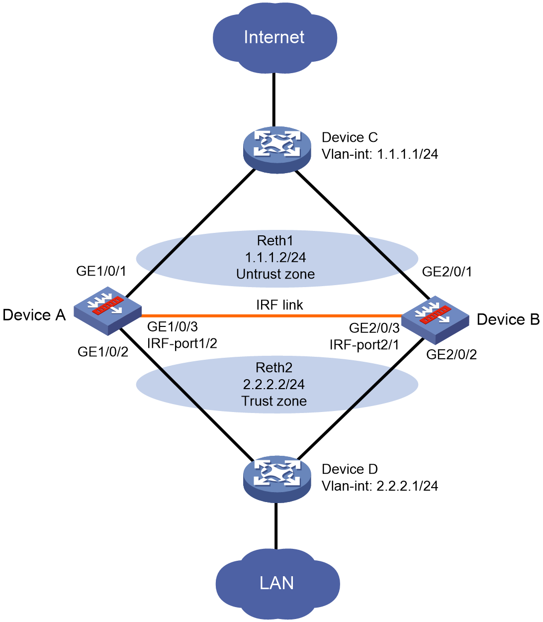
As shown in Figure 7, Device A (member ID 1) and Device B (member ID 2) form an IRF fabric. The IRF fabric connects to Device C and Device D through Reth 1 and Reth 2, respectively. Device C and Device D each use a VLAN interface to communicate with the IRF fabric.
Configure a redundancy group on the IRF fabric to ensure that traffic is forwarded along the Device C—Device A—Device D path when the path is available. When a link or device failure occurs on the path, traffic is switched to the Device C—Device B—Device D path.
This configuration example provides only redundancy group configuration. For more information about IRF fabric setup, see Virtual Technologies Configuration Guide.
Procedure
1. Configure IRF as described in "Example: Configuring a redundancy group with Layer 3 interface members."
2. Configure Reth interfaces:
# Create Reth 1 and enter its view.
<DeviceA> system-view
[DeviceA] interface reth 1
# Assign an IP address to Reth 1.
[DeviceA-Reth1] ip address 1.1.1.2 24
# Assign GigabitEthernet 1/0/1 and GigabitEthernet 2/0/1 to Reth 1, and set their priority to 255 and 50, respectively.
[DeviceA-Reth1] member interface gigabitethernet 1/0/1 priority 255
[DeviceA-Reth1] member interface gigabitethernet 2/0/1 priority 50
[DeviceA-Reth1] quit
# Create Reth 2 and enter its view.
[DeviceA] interface reth 2
# Assign an IP address to Reth 2.
[DeviceA-Reth2] ip address 2.2.2.2 24
# Assign GigabitEthernet 1/0/2 and GigabitEthernet 2/0/2 to Reth 2, and set their priority to 255 and 50, respectively.
[DeviceA-Reth2] member interface gigabitethernet 1/0/2 priority 255
[DeviceA-Reth2] member interface gigabitethernet 2/0/2 priority 50
[DeviceA-Reth2] quit
3. Create track entries to monitor the link state of the interfaces.
[DeviceA] track 1 interface gigabitethernet 1/0/1 physical
[DeviceA-track-1] quit
[DeviceA] track 2 interface gigabitethernet 1/0/2 physical
[DeviceA-track-2] quit
[DeviceA] track 3 interface gigabitethernet 2/0/1 physical
[DeviceA-track-3] quit
[DeviceA] track 4 interface gigabitethernet 2/0/2 physical
[DeviceA-track-4] quit
4. Configure a redundancy group:
# Create redundancy group aaa and create node 1 for the redundancy group.
[DeviceA] redundancy group aaa
[DeviceA-redundancy-group-aaa] node 1
# Bind node 1 to Device A.
[DeviceA-redundancy-group-aaa-node1] bind slot 1
# Set the priority of node 1 to 100.
[DeviceA-redundancy-group-aaa-node1] priority 100
# Associate track entries 1 and 2 with node 1. Exclude GigabitEthernet 1/0/1 and GigabitEthernet 1/0/2 from the shutdown action by the Reth module.
[DeviceA-redundancy-group-aaa-node1] track 1 interface gigabitethernet 1/0/1
[DeviceA-redundancy-group-aaa-node1] track 2 interface gigabitethernet 1/0/2
[DeviceA-redundancy-group-aaa-node1] quit
# Create node 2 for redundancy group aaa.
[DeviceA-redundancy-group-aaa] node 2
# Bind node 2 to Device B.
[DeviceA-redundancy-group-aaa-node2] bind slot 2
# Set the priority of node 2 to 50.
[DeviceA-redundancy-group-aaa-node2] priority 50
# Associate track entries 3 and 4 with node 2. Exclude GigabitEthernet 2/0/1 and GigabitEthernet 2/0/2 from the shutdown action by the Reth module.
[DeviceA-redundancy-group-aaa-node2] track 3 interface gigabitethernet 2/0/1
[DeviceA-redundancy-group-aaa-node2] track 4 interface gigabitethernet 2/0/2
[DeviceA-redundancy-group-aaa-node2] quit
# Assign Reth 1 and Reth 2 to redundancy group aaa.
[DeviceA-redundancy-group-aaa] member interface reth 1
[DeviceA-redundancy-group-aaa] member interface reth 2
[DeviceA-redundancy-group-aaa] quit
5. Configure settings for routing.
This example configures static routes, and the next hops in the routes are 1.1.1.1 and 2.2.2.1.
[DeviceA] ip route-static 0.0.0.0 0 1.1.1.1
[DeviceA] ip route-static 3.3.3.0 24 2.2.2.1
6. Add interfaces to security zones.
[DeviceA] security-zone name untrust
[DeviceA-security-zone-Untrust] import interface reth 1
[DeviceA-security-zone-Untrust] quit
[DeviceA] security-zone name trust
[DeviceA-security-zone-Trust] import interface reth 2
[DeviceA-security-zone-Trust] quit
7. Configure a security policy. Configure a rule named trust-untrust to permit the packets between the LAN and the external network.
[DeviceA] security-policy ip
[DeviceA-security-policy-ip] rule 1 name trust-untrust
[DeviceA-security-policy-ip-1-trust-untrust] source-zone trust
[DeviceA-security-policy-ip-1-trust-untrust] destination-zone untrust
[DeviceA-security-policy-ip-1-trust-untrust] source-ip-subnet 3.3.3.0 24
[DeviceA-security-policy-ip-1-trust-untrust] action pass
[DeviceA-security-policy-ip-1-trust-untrust] quit
[DeviceA-security-policy-ip] quit
Verifying the configuration
# Verify that node 1 is the primary node in redundancy group aaa.
[DeviceA] display redundancy group aaa
Redundancy group aaa (ID 1):
Node ID Slot Priority Status Track weight
Node1 Slot1 100 Primary 255
Node2 Slot2 50 Secondary 255
Preempt delay time remained : 0 min
Preempt delay timer setting : 1 min
Remaining hold-down time : 0 sec
Hold-down timer setting : 300 sec
Manual switchover request : No
Node 1:
Track info:
Track Status Reduced weight Interface
1 Positive 255 GE1/0/1
2 Positive 255 GE1/0/2
Node 2:
Track info:
Track Status Reduced weight Interface
3 Positive 255 GE2/0/1
4 Positive 255 GE2/0/2
# Verify that GigabitEthernet 1/0/1 of Reth 1 and GigabitEthernet 1/0/2 of Reth 2 are active.
[DeviceA] display reth interface reth 1
Reth1 :
Redundancy group : aaa
Member Physical status Forwarding status Presence status
GE1/0/1 UP Active Normal
GE2/0/1 UP Inactive Normal
[DeviceA] display reth interface reth 2
Reth2 :
Redundancy group : aaa
Member Physical status Forwarding status Presence status
GE1/0/2 UP Active Normal
GE2/0/2 UP Inactive Normal
# Shut down GigabitEthernet 1/0/2.
[DeviceA] interface gigabitethernet 1/0/2
[DeviceA-GigabitEthernet1/0/2] shutdown
# Verify that node 2 has become the primary node in redundancy group aaa.
[DeviceA-GigabitEthernet1/0/2] display redundancy group aaa
Redundancy group aaa (ID 1):
Node ID Slot Priority Status Track weight
Node1 Slot1 100 Secondary -255
Node2 Slot2 50 Primary 255
Preempt delay time remained : 0 min
Preempt delay timer setting : 1 min
Remaining hold-down time : 0 sec
Hold-down timer setting : 300 sec
Manual switchover request : No
Node 1:
Track info:
Track Status Reduced weight Interface
1 Negative 255 GE1/0/1
2 Negative(Faulty) 255 GE1/0/2(Fault)
Node 2:
Track info:
Track Status Reduced weight Interface
3 Positive 255 GE2/0/1
4 Positive 255 GE2/0/2
# Verify that GigabitEthernet 1/0/1 has been shut down by the Reth module, and GigabitEthernet 2/0/1 and GigabitEthernet 2/0/2 are active.
[DeviceA-GigabitEthernet1/0/2] display reth interface reth 1
Reth1 :
Redundancy group : aaa
Member Physical status Forwarding status Presence status
GE1/0/1 DOWN(redundancy down) Inactive Normal
GE2/0/1 UP Active Normal
[DeviceA-GigabitEthernet1/0/2] display reth interface reth 2
Reth2 :
Redundancy group : aaa
Member Physical status Forwarding status Presence status
GE1/0/2 DOWN Inactive Normal
GE2/0/2 UP Active Normal
