- Table of Contents
- Related Documents
-
| Title | Size | Download |
|---|---|---|
| 02-Context configuration | 237.83 KB |
Contents
Default context and non-default contexts
Restrictions: Hardware compatibility with context configuration
Restrictions and guidelines: Context configuration
Assigning interfaces and VLANs to a context
Assigning interfaces to a context
Limiting resource use for a context
Setting the outbound throughput threshold
Setting the maximum number of security policy rules
Setting the maximum number of concurrent unicast sessions
Setting the upper limit of the session establishment rate
Setting the maximum number of SSL VPN users
Assigning CPU, disk, and memory resources to a context
About CPU, disk, and memory resources assignment
Specifying a CPU weight for a context
Specifying a disk space percentage for a context
Specifying a memory space percentage for a context
Configuring inbound rate limiting for contexts
Configuring inbound broadcast rate limiting
Configuring inbound multicast rate limiting
Enabling logging for packets dropped because of rate limiting
Setting the CPU usage threshold per CPU core for attack prevention
Archiving log messages for contexts
Configuring a context to support inter-VPC connectivity
Display and maintenance commands for contexts
Context configuration examples
Example: Configuring a context to support inter-VPC connectivity
Example: Configuring contexts to act as gateways in a cloud computing center
Configuring contexts
About contexts
A physical device or an IRF fabric can be virtualized into multiple logical devices called contexts. Each context is assigned separate hardware and software resources, and operates independently of other contexts. From the user's perspective, a context is a standalone device.
Context applications
With context technology, you can meet device requirements from different branches or companies by using a single physical device.
As shown in Figure 1, LAN 1, LAN 2, and LAN 3 are connected to the Internet through the same device. To provide secure access services for the three LANs, you can deploy a single physical device and configure a context for each LAN on the device. The administrator of each LAN can only log in to and manage its own context without affecting other LANs. This has the same effect as deploying a separate device for each LAN.
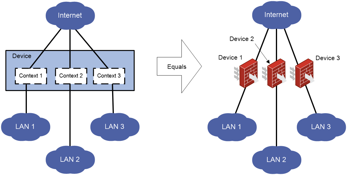
Default context and non-default contexts
A device supporting contexts is considered to be a context. This context is called the default context (for example, Device in Figure 1). The default context always uses the name Admin and the ID 1. You cannot delete it or change its name or ID.
When you log in to the physical device, you are logged in to the default context. On the default context, you can perform the following tasks:
· Manage the entire physical device.
· Create and delete non-default contexts (for example, Context 1, Context 2, and Context 3 in Figure 1).
· Assign resources to non-default contexts. These resources include CPU resources, disk spaces, memory spaces, interfaces, and VLANs.
Administrators of non-default contexts can only use resources assigned to their own contexts. They cannot use free resources or create other contexts. Resources that are not assigned to any non-default context belong to the default context.
A non-default context does not support packet capture on shared interfaces. For more information about packet capture, see Network Management and Monitoring Configuration Guide.
Restrictions: Hardware compatibility with context configuration
|
F1000 series |
Models |
Context compatibility |
|
F1000-X-G5 series |
F1000-A-G5, F1000-C-G5, F1000-C-G5-LI, F1000-E-G5, F1000-H-G5, F1000-S-G5 |
Yes |
|
F1000-X-G3 series |
F1000-A-G3, F1000-C-G3, F1000-E-G3, F1000-S-G3 |
Yes |
|
F1000-X-G2 series |
F1000-A-G2, F1000-C-G2, F1000-E-G2, F1000-S-G2 |
Yes |
|
F1000-9X0-AI series |
F1000-9390-AI, F1000-9385-AI, F1000-9380-AI, F1000-9370-AI, F1000-9360-AI, F1000-9350-AI, F1000-990-AI, F1000-980-AI, F1000-970-AI, F1000-960-AI, F1000-950-AI, F1000-930-AI, F1000-920-AI |
Yes |
|
F1000-9330-AI, F1000-9320-AI, F1000-910-AI, F1000-905-AI |
No |
|
|
F1000-C83X0 series |
F1000-C8395, F1000-C8390, F1000-C8385, F1000-C8380, F1000-C8370, F1000-C8360, F1000-C8350 |
Yes |
|
F1000-C8330 |
No |
|
|
F1000-C81X0 series |
F1000-C8180, F1000-C8170, F1000-C8160 |
Yes |
|
F1000-C8150, F1000-C8130, F1000-C8120, F1000-C8110 |
No |
|
|
F1000-7X0-HI series |
F1000-770-HI, F1000-750-HI, F1000-740-HI |
Yes |
|
F1000-730-HI, F1000-720-HI, F1000-710-HI |
No |
|
|
F1000-C-X series |
F1000-C-EI, F1000-C-HI, F1000-C-XI, F1000-E-XI |
Yes |
|
F1000-V series |
F1000-E-VG |
Yes |
|
F1000-S-VG |
No |
|
|
SecBlade IV |
LSPM6FWD8, LSQM2FWDSC8 |
Yes |
|
F100 series |
Models |
Context compatibility |
|
F100-X-G5 series |
F100-A-G5, F100-C-G5, F100-M-G5, F100-S-G5 |
No |
|
F100-E-G5 |
Yes |
|
|
F100-X-G3 series |
F100-A-G3, F100-E-G3 |
Yes |
|
F100-C-G3, F100-M-G3, F100-S-G3 |
No |
|
|
F100-X-G2 series |
F100-A-G2, F100-E-G2 |
Yes |
|
F100-C-G2, F100-M-G2, F100-S-G2 |
No |
|
|
F100-WiNet series |
F100-A91-WiNet, F100-A80-WiNet |
Yes |
|
F100-A81-WiNet, F100-C80-WiNet, F100-C60-WiNet, F100-C50-WiNet, F100-S80-WiNet |
No |
|
|
F100-C-A series |
F100-C-A6, F100-C-A5, F100-C-A3, F100-C-A2, F100-C-A1, F100-C-A6-WL, F100-C-A5-W, F100-C-A3-W |
No |
|
F100-X-XI series |
F100-A-EI, F100-A-HI, F100-A-SI, F100-E-EI |
Yes |
|
F100-C-EI, F100-C-HI, F100-C-XI, F100-S-HI, F100-S-XI |
No |
Restrictions and guidelines: Context configuration
All commands in this chapter are supported on the default context. On a non-default context, only the display context interface, display context reboot, and reset context reboot commands are supported.
DPI services on non-default contexts use the DPI engine on the default context for packet matching. Creating, deleting, stopping, or restarting a non-default context re-activates the DPI engine on the default context. Before the DPI engine on the default context operates correctly, no contexts can provide DPI services.
Context tasks at a glance
To configure contexts, perform the following tasks:
2. (Optional.) Assigning interfaces and VLANs to a context
¡ Assigning interfaces to a context
¡ Assigning VLANs to a context
3. (Optional.) Limiting resource use for a context
¡ Setting the outbound throughput threshold
¡ Setting the maximum number of security policy rules
¡ Setting the maximum number of concurrent unicast sessions
¡ Setting the upper limit of the session establishment rate
¡ Setting the maximum number of SSL VPN users
5. (Optional.) Assigning CPU, disk, and memory resources to a context
¡ Specifying a CPU weight for a context
¡ Specifying a disk space percentage for a context
¡ Specifying a memory space percentage for a context
7. (Optional.) Configuring inbound rate limiting for contexts
8. (Optional.) Setting the CPU usage threshold per CPU core for attack prevention
9. (Optional.) Archiving log messages for contexts
10. (Optional.) Configuring a context to support inter-VPC connectivity
Creating contexts
Restrictions and guidelines
When you create a context, you can assign it the VLAN-unshared attribute as required.
· A context with the VLAN-unshared attribute has its own VLAN resources (VLAN 2 through VLAN 4094). It does not share VLAN resources with any other context. To create VLANs for the context, log in to the context and use the vlan command. VLAN 1 is system defined. You cannot create or delete VLAN 1.
· All contexts without the VLAN-unshared attribute share the same VLAN resources (VLAN 1 through VLAN 4094). You can create VLANs on the default context and use the allocate vlan command to assign VLANs to the contexts. A VLAN can be assigned only to one context. VLAN 1 is system defined. It belongs to the default context. You cannot assign it to a non-default context.
For a context without the VLAN-unshared attribute, you cannot perform the following tasks:
¡ Change the link mode of Layer 3 Ethernet interfaces on the context to Layer 2.
¡ Assign a Layer 2 Ethernet interface exclusively to the context.
Procedure
1. Enter system view.
system-view
2. Create a context and enter context view.
context context-name [ id context-id ] [ vlan-unshared ]
By default, a default context exists. The context name is Admin and the context ID is 1.
3. Configure a description for the context.
description text
By default, the default context uses the description DefaultContext, and a non-default context does not have a description.
Assigning interfaces and VLANs to a context
Assigning interfaces to a context
About this task
By default, all interfaces belong to the default context. A non-default context cannot use any interfaces. To enable a non-default context to communicate, you must assign it interfaces.
You can assign interfaces to contexts in exclusive or shared mode:
· Exclusive mode—You assign an interface exclusively to a context, and only the context can use the interface. The administrator of the context can see the interface and use all commands supported on the interface.
· Shared mode—You assign an interface to multiple contexts in shared mode, and the system creates a virtual interface for each context. The virtual interfaces use the same name as the physical interface but have different MAC addresses and IP addresses. They forward and receive packets through the physical interface. The shared mode improves interface usage.
You can see the physical interface and perform all commands supported on the interface from the default context. The administrator of a context can only see the context's virtual interface and use the shutdown, description, and network- and security-related commands.
Restrictions and guidelines
Do not assign IRF physical interfaces to a non-default context.
Do not assign member interfaces of an aggregate interface to a non-default context.
If a subinterface of a Layer 3 interface is a member interface of a Reth interface, do not assign the Layer 3 interface to a non-default context.
A logical interface (for example, a subinterface or aggregate interface) can be assigned to a context only in shared mode.
After assigning a subinterface to a context, you cannot assign its primary interface to a context. After assigning a primary interface to a context, you cannot assign its subinterfaces to a context.
After assigning an interface to contexts in shared mode, you cannot assign the interface to contexts in exclusive mode before reclaiming the interface.
For non-default contexts to communicate with each other, you must assign physical or logical interfaces to the non-default contexts in shared mode on the default context.
Procedure
1. Enter system view.
system-view
2. Enter context view.
context context-name
3. Assign interfaces to the context.
¡ Assign individual interfaces to the context.
allocate interface { interface-type interface-number }&<1-24> [ share ]
¡ Assign a range of interfaces to the context.
allocate interface interface-type interface-number1 to interface-type interface-number2 [ share ]
By default, all interfaces belong to the default context. A non-default context cannot use any interfaces.
Assigning VLANs to a context
Restrictions and guidelines
For contexts without the VLAN-unshared attribute, you can only assign VLANs to them and cannot use the vlan command to create VLANs for them. Before the assignment, you must create the VLANs on the default context. A VLAN can be assigned only to one context.
You cannot assign the following VLANs to a context without the VLAN-unshared attribute:
· VLAN 1.
· Default VLANs of interfaces.
· VLANs for which you have created VLAN interfaces.
Procedure
1. Enter system view.
system-view
2. Enter context view.
context context-name
3. Assign VLANs to the context.
¡ Assign individual VLANs to the context.
allocate vlan vlan-id&<1-24>
¡ Assign a range of VLANs to the context.
allocate vlan vlan-id1 to vlan-id2
By default, no VLANs are assigned to a context.
Limiting resource use for a context
Setting the outbound throughput threshold
About this task
This feature limits the outbound throughput for a context to prevent it from occupying too many shared resources on a security engine.
Procedure
1. Enter system view.
system-view
2. Enter context view.
context context-name
3. Set the outbound throughput threshold on the context.
capability throughput { kbps | pps } value
By default, the outbound throughput is not limited on a context.
Setting the maximum number of security policy rules
About this task
A large number of rules occupy too much memory, affecting other features on the context. This feature limits the number of security policy rules for a context. When the maximum number is reached, you cannot add new rules. For information about security policies, see Security Configuration Guide.
Restrictions and guidelines
If the maximum number you set is smaller than the number of existing security policy rules, this setting takes effect. The context does not delete extra existing security policy rules and allows new security policy rules to be created only when the number of security policy rules drops below the maximum number.
Procedure
1. Enter system view.
system-view
2. Enter context view.
context context-name
3. Set the maximum number of security policy rules.
capability security-policy-rule maximum max-value
By default, the number of security policy rules is not limited for a context.
Setting the maximum number of concurrent unicast sessions
About this task
A large number of sessions occupy too much memory, affecting establishment of sessions on other contexts. This feature limits the number of concurrent unicast sessions for a context. When the maximum number is reached, you cannot establish additional unicast sessions.
This feature does not affect local traffic, such as FTP traffic, Telnet traffic, SSH traffic, HTTP traffic, and HTTP-based load balancing traffic.
Restrictions and guidelines
If the maximum number you set is smaller than the number of existing concurrent unicast sessions, this setting takes effect. The context does not delete extra existing concurrent unicast sessions and allows new unicast sessions to be created only when the number of concurrent unicast sessions drops below the maximum number.
Procedure
1. Enter system view.
system-view
2. Enter context view.
context context-name
3. Set the maximum number of concurrent unicast sessions.
capability session maximum max-number
By default, the number of concurrent unicast sessions is not limited.
Setting the upper limit of the session establishment rate
About this task
Establishing sessions too frequently consumes too much CPU resources. If a context establishes sessions too frequently, other contexts will not be able to establish sessions. This feature limits the number of sessions that can be established per second for a context. When the upper limit is reached for a context, no additional sessions can be established.
This feature does not affect local traffic, such as FTP traffic, Telnet traffic, SSH traffic, HTTP traffic, and HTTP-based load balancing traffic.
Procedure
1. Enter system view.
system-view
2. Enter context view.
context context-name
3. Set the upper limit of the session establishment rate.
capability session rate max-value
By default, the session establishment rate is not limited for a context.
Setting the maximum number of SSL VPN users
About this task
The maximum number of SSL VPN users allowed on the device is license-restricted. If the number of logged-in users in a context already reaches the total upper limit, other contexts cannot accept login requests. This feature limits the number of SSL VPN users that can log in to a context. When the maximum number is reached, the context will reject the login requests of new SSL VPN users.
Restrictions and guidelines
If the maximum number you set is smaller than the number of SSL VPN users that already have logged in to a context, this setting takes effect. The context does not log out the currently logged-in users and allows new users to log in only when the number of the logged-in users drops below the maximum number.
Procedure
1. Enter system view.
system-view
2. Enter context view.
context context-name
3. Set the maximum number of SSL VPN users.
capability sslvpn-user maximum max-number
By default, the number of SSL VPN users is not limited for a context. The number is determined by the usage of the SSL VPN licenses installed on the device.
Starting a context
About this task
You must perform this task to initialize a newly created context. You can configure a context only after it is started.
When a context starts, the device examines whether requirements for starting the context are met to ensure status consistency between the master and backup contexts and correct operation of the context.
In an IRF fabric, memory insufficiency might occur during master and backup switchover or configuration recovery. Some contexts will stay in updating or inactive status because of status inconsistency between master and backup processes although they can process services. Use the context start force command to forcibly start these contexts after the memory becomes sufficient. The device will recover the abnormal context processes without service interruption.
Restrictions and guidelines
Before using the context start force command, you can use the following commands to display the context running information:
· display context
· display system internal context configuration-status
· display system internal context id context-id running-status
Procedure
1. Enter system view.
system-view
2. Enter context view.
context context-name
3. Start the context.
context start [ force ]
By default, a context is not started.
Assigning CPU, disk, and memory resources to a context
About CPU, disk, and memory resources assignment
When you assign a context to a security engine group, the system automatically assigns CPU, disk space, and memory space resources on the security engines to the context. All contexts residing on the same security engine share and compete for the engine's free CPU, disk, and memory resources. To prevent one context from occupying too many resources, assign CPU, disk space resources, and memory space resources to the contexts. To assign resources to a context, specify a CPU weight, disk space percentage, and memory space percentage for the context.
Specifying a CPU weight for a context
About this task
When the CPU resources on a security engine cannot meet the processing requirements from contexts, the system allocates CPU resources on the engine as follows:
1. Identifies the CPU weights of all contexts on the engine.
2. Calculates the percentage of each context's CPU weight among the CPU weights of all contexts.
3. Allocates CPU resources to contexts based on their CPU weight percentages.
For example, three contexts share the same CPU. You can assign a weight of 2 to the key context and a weight of 1 to each of the other two contexts. When the system is running out of CPU resources, the key context can use approximately two times of the CPU resources that each of the other two contexts can use.
Procedure
1. Enter system view.
system-view
2. Enter context view.
context context-name
3. Specify a CPU weight for the context.
limit-resource cpu weight weight-value
By default, each context has a CPU weight of 10.
Specifying a disk space percentage for a context
Restrictions and guidelines
Before a context starts, its disk space usage is 0. If the configured disk space limit is smaller than the disk space required for starting the context, the context might not start correctly. As a best practice, make sure the context is started correctly before specifying a disk space percentage for a context.
Hardware and feature compatibility
|
F1000 series |
Models |
Feature compatibility |
|
F1000-X-G5 series |
F1000-A-G5, F1000-C-G5, F1000-C-G5-LI, F1000-E-G5, F1000-H-G5, F1000-S-G5 |
No |
|
F1000-X-G3 series |
F1000-A-G3, F1000-C-G3, F1000-E-G3, F1000-S-G3 |
No |
|
F1000-X-G2 series |
F1000-A-G2, F1000-C-G2, F1000-E-G2, F1000-S-G2 |
Yes |
|
F1000-9X0-AI series |
F1000-990-AI, F1000-980-AI, F1000-970-AI, F1000-960-AI, F1000-950-AI, F1000-930-AI, F1000-920-AI |
Yes |
|
F1000-9390-AI, F1000-9385-AI, F1000-9380-AI, F1000-9370-AI, F1000-9360-AI, F1000-9350-AI, F1000-9330-AI, F1000-9320-AI, F1000-910-AI, F1000-905-AI |
No |
|
|
F1000-C83X0 series |
F1000-C8395, F1000-C8390, F1000-C8385, F1000-C8380, F1000-C8370, F1000-C8360, F1000-C8350, F1000-C8330 |
No |
|
F1000-C81X0 series |
F1000-C8180, F1000-C8170, F1000-C8160 |
Yes |
|
F1000-C8150, F1000-C8130, F1000-C8120, F1000-C8110 |
No |
|
|
F1000-7X0-HI series |
F1000-770-HI, F1000-750-HI, F1000-740-HI, F1000-730-HI, F1000-720-HI, F1000-710-HI |
No |
|
F1000-C-X series |
F1000-C-EI, F1000-C-HI |
Yes |
|
F1000-C-XI, F1000-E-XI |
No |
|
|
F1000-V series |
F1000-E-VG |
Yes |
|
F1000-S-VG |
No |
|
|
SecBlade IV |
LSPM6FWD8, LSQM2FWDSC8 |
Yes |
|
F100 series |
Models |
Feature compatibility |
|
F100-X-G5 series |
F100-A-G5, F100-C-G5, F100-E-G5, F100-M-G5, F100-S-G5 |
No |
|
F100-X-G3 series |
F100-A-G3, F100-E-G3 |
Yes |
|
F100-C-G3, F100-M-G3, F100-S-G3 |
No |
|
|
F100-X-G2 series |
F100-A-G2, F100-E-G2 |
Yes |
|
F100-C-G2, F100-M-G2, F100-S-G2 |
No |
|
|
F100-WiNet series |
F100-A80-WiNet |
Yes |
|
F100-A91-WiNet, F100-A81-WiNet, F100-C80-WiNet, F100-C60-WiNet, F100-C50-WiNet, F100-S80-WiNet |
No |
|
|
F100-C-A series |
F100-C-A6, F100-C-A5, F100-C-A3, F100-C-A2, F100-C-A1, F100-C-A6-WL, F100-C-A5-W, F100-C-A3-W |
No |
|
F100-X-XI series |
F100-A-EI, F100-A-HI, F100-A-SI, F100-E-EI |
Yes |
|
F100-C-EI, F100-C-HI, F100-C-XI, F100-S-HI, F100-S-XI |
No |
Procedure
1. Enter system view.
system-view
2. Enter context view.
context context-name
3. Display the amount of disk space that has been used by the context.
display context resource disk
4. Specify a disk space percentage for the context.
limit-resource disk slot slot-number cpu cpu-number ratio limit-ratio
By default, all contexts share the memory space in the system. A context can use all free disk space.
The setting takes effect on all the storage media.
Support for this command depends on device model.
Specifying a memory space percentage for a context
Restrictions and guidelines
To prevent a context from start failures because of memory space insufficiency, specify a memory space percentage for the context after the context has started correctly.
After the context starts, make sure the configured memory space limit meets the memory space needs of the services provided by the context.
Procedure
1. Enter system view.
system-view
2. Enter context view.
context context-name
3. Display the amount of memory space that has been used by the context.
display context resource memory
4. Specify a memory space percentage for the context.
limit-resource memory slot slot-number cpu cpu-number ratio limit-ratio
By default, all contexts share the memory space in the system. A context can use all free memory space.
Accessing a context
About this task
From the system view of the default context, you can log in to a non-default context and enter the context's user view.
You can also access a context by using Telnet and SSH.
Procedure
1. Enter system view.
system-view
2. Log in to a context.
switchto context context-name
To return to the default context, use the quit command.
Configuring inbound rate limiting for contexts
Configuring inbound broadcast rate limiting
About this task
Inbound broadcast rate limiting controls the rates of incoming broadcast packets on contexts. This feature can prevent a context from using too many resources and degrading the service processing capabilities of other contexts.
Inbound broadcast rate limiting uses the following types of limits:
· Per-context broadcast rate limit—Limit on the rate of incoming broadcast packets on a single context.
· Total broadcast rate limit—Limit on the total rate of incoming broadcast packets on all contexts.
When both a per-context broadcast rate limit and the total broadcast rate limit are reached, the device drops subsequent broadcast packets that arrive at the context.
Restrictions and guidelines
This feature applies only to inbound broadcast packets.
This feature takes effect only on active contexts that share interfaces with other contexts.
Setting the total inbound broadcast rate limit to 0 disables the inbound broadcast rate limiting feature.
Procedure
1. Enter system view.
system-view
2. Set the total inbound broadcast rate limit.
context-capability inbound broadcast total pps threshold
The default setting varies by device model. For more information, see the command reference.
3. Set the inbound broadcast rate limit for the default context.
context-capability inbound broadcast single pps threshold
By default, the inbound broadcast rate limit for the default context is the total rate limit divided by the number of active contexts that share interfaces with other contexts.
4. Enter the view of a non-default context.
context context-name
5. Set the inbound broadcast rate limit for the context.
context-capability inbound broadcast single pps threshold
By default, the inbound broadcast rate limit for a non-default context is the total rate limit divided by the number of active contexts that share interfaces with other contexts.
Configuring inbound multicast rate limiting
About this task
Inbound multicast rate limiting controls the rates of incoming multicast packets on contexts. This feature can prevent a context from using too many resources and degrading the service processing capabilities of other contexts.
Inbound multicast rate limiting uses the following types of limits:
· Per-context multicast rate limit—Limit on the rate of incoming multicast packets on a single context.
· Total multicast rate limit—Limit on the total rate of incoming multicast packets on all contexts.
When both a per-context inbound multicast rate limit and the total inbound multicast rate limit are reached, the device drops subsequent multicast packets that arrive at the context.
Restrictions and guidelines
This feature applies only to inbound multicast packets.
This feature takes effect only on active contexts that share interfaces with other contexts.
Setting the total inbound multicast rate limit to 0 disables the inbound multicast rate limiting feature.
Procedure
1. Enter system view.
system-view
2. Set the total inbound multicast rate limit.
context-capability inbound multicast total pps threshold
The default setting varies by device model. For more information, see the command reference.
3. Set the inbound multicast rate limit for the default context.
context-capability inbound multicast single pps threshold
By default, the inbound multicast rate limit for the default context is the total rate limit divided by the number of active contexts that share interfaces with other contexts.
4. Enter the view of a non-default context.
context context-name
5. Set the multicast rate limit for the context.
context-capability inbound multicast single pps threshold
By default, the inbound multicast rate limit for a non-default context is the total rate limit divided by the number of active contexts that share interfaces with other contexts.
Enabling logging for packets dropped because of rate limiting
About this task
This logging feature generates and sends a log message to the information center when an incoming packet is dropped because of rate limiting on contexts. For more information about how the information center manages log messages, see information center configuration in Network Management and Monitoring Configuration Guide.
Procedure
1. Enter system view.
system-view
2. Enable logging for incoming packets dropped because of rate limiting on contexts.
context-capability inbound drop-logging enable
By default, logging is disabled for incoming packets that are dropped because of rate limiting on contexts.
Setting the CPU usage threshold per CPU core for attack prevention
About this task
Perform this task to set the CPU usage threshold per CPU core for all inbound packets from all contexts. The specified threshold applies to all inbound packets, including broadcast, unicast, and multicast packets.
If the shared queue in the driver is full when the total usage of a CPU core reaches the specified threshold, the system determines that an attack risk is present. Then, it takes the attack prevention action configured by using the attack-defense cpu-core action command until the attack risk is eliminated. For more information about the attack-defense cpu-core action command, see attack detection and prevention commands in Security Command Reference.
Hardware and feature compatibility
|
F1000 series |
Models |
Feature compatibility |
|
F1000-X-G5 series |
F1000-A-G5, F1000-E-G5, F1000-H-G5, F1000-S-G5 |
Yes |
|
F1000-C-G5, F1000-C-G5-LI |
No |
|
|
F1000-X-G3 series |
F1000-A-G3, F1000-C-G3, F1000-E-G3, F1000-S-G3 |
Yes |
|
F1000-X-G2 series |
F1000-A-G2, F1000-C-G2, F1000-E-G2, F1000-S-G2 |
No |
|
F1000-9X0-AI series |
F1000-9390-AI, F1000-9385-AI, F1000-9380-AI, F1000-9370-AI |
Yes |
|
F1000-9360-AI, F1000-9350-AI, F1000-9330-AI, F1000-9320-AI, F1000-990-AI, F1000-980-AI, F1000-970-AI, F1000-960-AI, F1000-950-AI, F1000-930-AI, F1000-920-AI, F1000-910-AI, F1000-905-AI |
No |
|
|
F1000-C83X0 series |
F1000-C8395, F1000-C8390, F1000-C8385, F1000-C8380 |
Yes |
|
F1000-C8370, F1000-C8360, F1000-C8350, F1000-C8330 |
No |
|
|
F1000-C81X0 series |
F1000-C8180, F1000-C8170, F1000-C8160, F1000-C8150, F1000-C8130, F1000-C8120, F1000-C8110 |
No |
|
F1000-7X0-HI series |
F1000-770-HI |
Yes |
|
F1000-750-HI, F1000-740-HI, F1000-730-HI, F1000-720-HI, F1000-710-HI |
No |
|
|
F1000-C-X series |
F1000-C-EI, F1000-C-HI, F1000-C-XI |
No |
|
F1000-E-XI |
Yes |
|
|
F1000-V series |
F1000-E-VG, F1000-S-VG |
No |
|
SecBlade IV |
LSPM6FWD8, LSQM2FWDSC8 |
No |
|
F100 series |
Models |
Feature compatibility |
|
F100-X-G5 series |
F100-A-G5, F100-C-G5, F100-E-G5, F100-M-G5, F100-S-G5 |
No |
|
F100-X-G3 series |
F100-A-G3, F100-C-G3, F100-E-G3, F100-M-G3, F100-S-G3 |
No |
|
F100-X-G2 series |
F100-A-G2, F100-C-G2, F100-E-G2, F100-M-G2, F100-S-G2 |
No |
|
F100-WiNet series |
F100-A91-WiNet, F100-A81-WiNet, F100-A80-WiNet, F100-C80-WiNet, F100-C60-WiNet, F100-C50-WiNet, F100-S80-WiNet |
No |
|
F100-C-A series |
F100-C-A6, F100-C-A5, F100-C-A3, F100-C-A2, F100-C-A1, F100-C-A6-WL, F100-C-A5-W, F100-C-A3-W |
No |
|
F100-X-XI series |
F100-A-EI, F100-A-HI, F100-A-SI, F100-C-EI, F100-C-HI, F100-C-XI, F100-E-EI, F100-S-HI, F100-S-XI |
No |
Procedure
1. Enter system view.
system-view
2. Set the CPU usage threshold per CPU core for all inbound packets from all contexts for attack prevention.
context-capability inbound unicast total cpu-usage threshold
By default, the CPU usage threshold per CPU core is 95%.
Archiving log messages for contexts
About this task
This feature archives all files in the logfile directory and diagfile directory.
Procedure
To archive log messages for contexts, execute this command in the user view:
tar context [ name context-name ] log file filename
Configuring a context to support inter-VPC connectivity
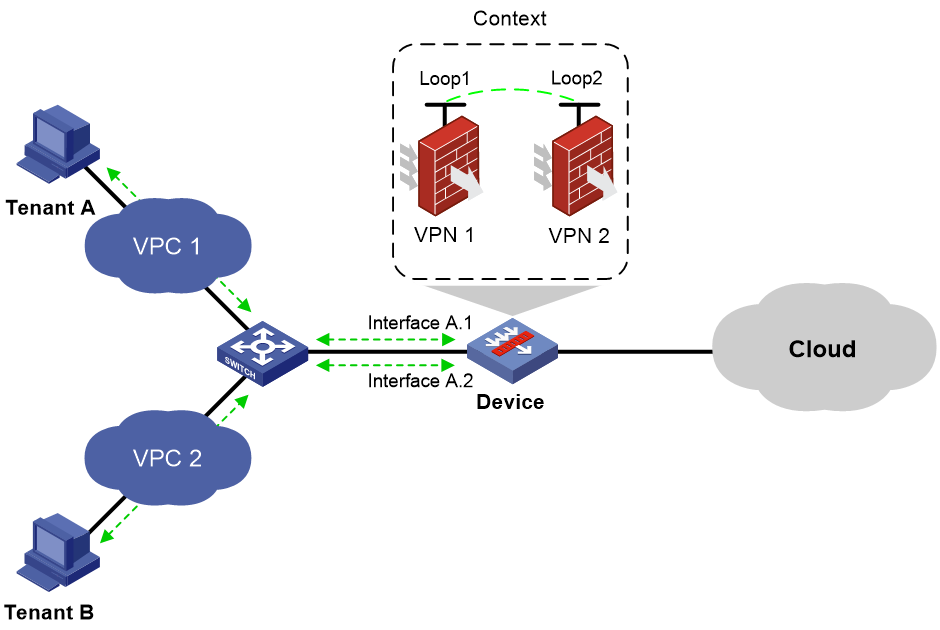
About this task
In a virtual private cloud (VPC) scenario, the following tasks are required for tenant isolation and inter-VPC connectivity:
· Configure VPN instances, each of which corresponds to a VPC, thus isolating traffic of tenants in different VPCs.
· Configure static routes for the VPN instances to implement interconnectivity of VPCs. In the static routes, loopback interfaces are specified as the output interfaces.
Figure 2 Inter-VPC connectivity
Restrictions and guidelines
If a context is configured to support inter-VPC connectivity, make sure you configure only compatible related services on the context. Compatibility of related services with inter-VPC connectivity is as follows:
· Packet filtering services such as security policy are supported. However, services that will change the IP address of packets such as NAT and load balancing are not supported.
· Static routing is supported.
As a best practice, use subinterfaces for the device to communicate with tenants in VPCs.
Procedure
1. Enter system view.
system-view
2. Create VPN instances and associate an interface with each VPN instance.
For more information, see VPN instance configuration in VPN Instance Configuration Guide.
3. Configure static routes for the VPN instances and specify loopback interfaces as the output interfaces for the static routes.
For more information, see static routing configuration and IPv6 static routing configuration in Layer 3—IP Routing Configuration Guide.
Display and maintenance commands for contexts
Execute display commands in any view on the default context.
Execute reset commands in user view on the default context.
|
Task |
Command |
|
Display contexts. |
display context [ name context-name ] [ verbose ] |
|
Display usage of allocable service resources for contexts. |
display context [ name context-name ] capability [ security-policy | session [ slot slot-number ] | sslvpn-user ] |
|
Display the inbound broadcast rate limit statitiscs for a context. |
display context name context-name capability inbound broadcast slot slot-number |
|
Display the inbound multicast rate limit statitiscs for a context. |
display context name context-name capability inbound multicast slot slot-number |
|
Display attack prevention statistics for CPU cores. |
display capability inbound unicast slot slot-number |
|
Display context configuration information. |
display context [ name context-name ] configuration [ file filename ] |
|
Display interfaces assigned to contexts. |
display context [ name context-name ] interface |
|
Display CPU, disk space, and memory usage of contexts. |
display context [ name context-name ] resource [ cpu | disk | memory ] [ slot slot-number cpu cpu-number ] |
|
Display resource statistics for contexts. |
display context [ name context-name ] statistics [ file filename ] |
|
Display non-default context reboot information. |
display context name context-name reboot show-number [ offset ] |
|
Display the number of online SSL VPN users on all contexts. |
display context online-users sslvpn |
|
Display VLAN lists for contexts. |
display context [ name context-name ] vlan |
|
Clear the inbound broadcast rate limit statistics for a context. |
reset context name context-name capability inbound broadcast slot slot-number |
|
Clear the inbound multicast rate limit statistics for a context. |
reset context name context-name capability inbound multicast slot slot-number |
|
Clear non-default context reboot information. |
reset context [ name context-name ] reboot |
Execute display commands in any view and reset commands in user view on a non-default context:
|
Task |
Command |
|
Display interfaces assigned to the context. |
display context [ name context-name ] interface |
|
Display reboot information about the current context. |
display context reboot show-number [ offset ] |
|
Clear reboot information about the current context. |
reset context reboot |
Context configuration examples
Example: Configuring contexts
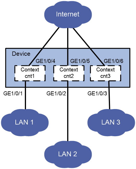
Network configuration
As shown in Figure 3, LAN 1, LAN 2, and LAN 3 use 192.168.1.0/24, 192.168.2.0/24, and 192.168.3.0/24, respectively.
Configure contexts for the LANs as follows:
· Configure context cnt1 for LAN 1. Assign 60% disk space and 60% memory space to the context and set the CPU weight to 8.
· Configure context cnt2 for LAN 2. Leave the context to use the default amount of disk space and the default amount of memory space.
· Configure context cnt3 for LAN 3. Set the CPU weight to 2.
Procedure
1. Configure context cnt1 for LAN 1.
# Create a context named cnt1 and configure a description for it.
[Device] context cnt1
[Device-context-2-cnt1] description context-1
# Set both the disk space percentage and memory space percentage to 60% and set the CPU weight to 8 for the context.
[Device-context-2-cnt1] limit-resource disk slot 1 cpu 0 ratio 60
[Device-context-2-cnt1] limit-resource memory slot 1 cpu 0 ratio 60
[Device-context-2-cnt1] limit-resource cpu weight 8
# Assign GigabitEthernet 1/0/1 and GigabitEthernet 1/0/4 to the context.
[Device-context-2-cnt1] allocate interface gigabitethernet 1/0/1 gigabitethernet 1/0/4
Configuration of the interfaces will be lost. Continue? [Y/N]:y
# Start the context.
[Device-context-2-cnt1] context start
It will take some time to start the context...
Context started successfully.
[Device-context-2-cnt1] quit
# Log in to the context from the default context.
[Device] switchto context cnt1
******************************************************************************
* Copyright (c) 2004-2021 New H3C Technologies Co., Ltd. All rights reserved.*
* Without the owner's prior written consent, *
* no decompiling or reverse-engineering shall be allowed. *
******************************************************************************
<H3C> system-view
# Configure Telnet login to enable remote context management. (Details not shown. For more information about Telnet login configuration, see login management in Fundamentals Configuration Guide.)
# Change the device name to cnt1 for easy identification of the context.
[H3C] sysname cnt1
# Assign IP address 192.168.1.251/24 to GigabitEthernet 1/0/1.
[cnt1] interface gigabitethernet 1/0/1
[cnt1-GigabitEthernet1/0/1] ip address 192.168.1.251 24
# Return to the default context.
[cnt1-GigabitEthernet1/0/1] return
<cnt1> quit
[Device]
2. Configure context cnt2 for LAN 2.
# Create a context named cnt2 and configure a description for it.
[Device-context-3-cnt2] description context-2
# Assign GigabitEthernet 1/0/2 and GigabitEthernet 1/0/5 to the context.
[Device-context-3-cnt2] allocate interface gigabitethernet 1/0/2 gigabitethernet 1/0/5
Configuration of the interfaces will be lost. Continue? [Y/N]:y
# Start the context.
[Device-context-3-cnt2] context start
It will take some time to start the context...
Context started successfully.
[Device-context-3-cnt2] quit
# Log in to the context from the default context.
[Device] switchto context cnt2
******************************************************************************
* Copyright (c) 2004-2021 New H3C Technologies Co., Ltd. All rights reserved.*
* Without the owner's prior written consent, *
* no decompiling or reverse-engineering shall be allowed. *
******************************************************************************
<H3C> system-view
# Configure Telnet login to enable remote context management. (Details not shown. For more information about Telnet login configuration, see login management in Fundamentals Configuration Guide.)
# Change the device name to cnt2 for easy identification of the context.
[H3C] sysname cnt2
# Assign IP address 192.168.2.251/24 to GigabitEthernet 1/0/2.
[cnt2] interface gigabitethernet 1/0/2
[cnt2-GigabitEthernet1/0/2] ip address 192.168.2.251 24
# Return to the default context.
[cnt2-GigabitEthernet1/0/2] return
<cnt2> quit
[Device]
3. Configure context cnt3 for LAN 3.
# Create a context named cnt3 and configure a description for it.
[Device-context-4-cnt3] description context-3
# Set the CPU weight to 2 for the context.
[Device-context-4-cnt3] limit-resource cpu weight 2
# Assign GigabitEthernet 1/0/3 and GigabitEthernet 1/0/6 to the context.
[Device-context-4-cnt3] allocate interface gigabitethernet 1/0/3 gigabitethernet 1/0/6
Configuration of the interfaces will be lost. Continue? [Y/N]:y
# Start the context.
[Device-context-4-cnt3] context start
It will take some time to start the context...
Context started successfully.
[Device-context-4-cnt3] quit
# Log in to the context from the default context.
[Device] switchto context cnt3
******************************************************************************
* Copyright (c) 2004-2021 New H3C Technologies Co., Ltd. All rights reserved.*
* Without the owner's prior written consent, *
* no decompiling or reverse-engineering shall be allowed. *
******************************************************************************
<H3C> system-view
# Configure Telnet login to enable remote context management. (Details not shown. For more information about Telnet login configuration, see login management in Fundamentals Configuration Guide.)
# Change the context name to cnt3 for easy identification of the context.
[H3C] sysname cnt3
# Assign IP address 192.168.3.251/24 to GigabitEthernet 1/0/3.
[cnt3] interface gigabitethernet 1/0/3
[cnt3-GigabitEthernet1/0/3] ip address 192.168.3.251 24
# Return to the default context.
[cnt3-GigabitEthernet1/0/3] return
<cnt3> quit
[Device]
Verifying the configuration
# Verify that the device has four contexts and all contexts are in active state.
[Device] display context
ID Name Status Description
1 Admin active DefaultContext
2 cnt1 active context-1
3 cnt2 active context-2
4 cnt3 active context-3
# Telnet to context cnt1 and view the running configuration on the context.
C:\> telnet 192.168.1.251
******************************************************************************
* Copyright (c) 2004-2021 New H3C Technologies Co., Ltd. All rights reserved.*
* Without the owner's prior written consent, *
* no decompiling or reverse-engineering shall be allowed. *
******************************************************************************
<cnt1> display current-configuration
...
Example: Configuring a context to support inter-VPC connectivity
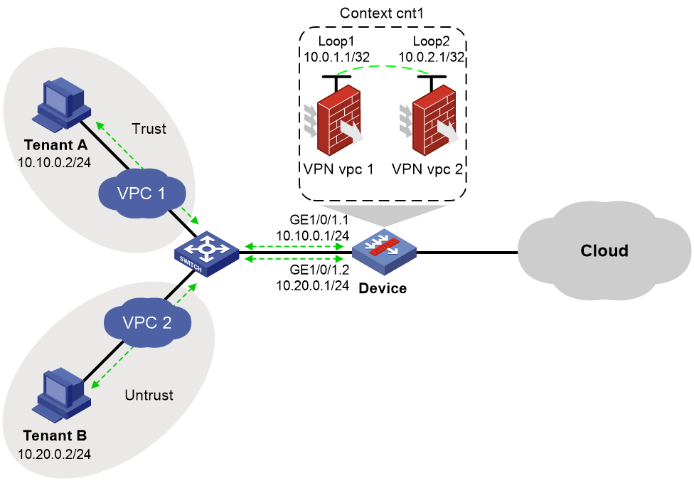
Network configuration
As shown in Figure 4, configure a context to provide security data access to the public cloud for tenants in VPCs as well as interconnectivity between the VPCs.
Procedure
1. Create a context.
# Create context cnt1, and assign CPU, memory, disk space, and interface resources to the context. For more information, see "Example: Configuring contexts." (Details not shown.)
2. Log in to context cnt1 from the default context.
<Device> system-view
[Device] switchto context cnt1
******************************************************************************
* Copyright (c) 2004-2020 New H3C Technologies Co., Ltd. All rights reserved.*
* Without the owner's prior written consent, *
* no decompiling or reverse-engineering shall be allowed. *
******************************************************************************
<H3C> system-view
# Configure Telnet to ensure that users can log in to the context. For more information, see login management configuration in Fundamentals Configuration Guide. (Details not shown.)
# Set the name of context cnt1 to cnt1.
[H3C] sysname cnt1
3. Create VPN instances, and associate interfaces with the VPN instances.
# Create VPN instances, configure loopback interfaces and Ethernet subinterfaces, and configure Ethernet subinterfaces to terminate VLAN-tagged packets with the specified outermost VLAN IDs.
[cnt1] ip vpn-instance vpc1
[cnt1-vpn-instance-vpc1] quit
[cnt1] ip vpn-instance vpc2
[cnt1-vpn-instance-vpc2] quit
[cnt1] interface loopback 1
[cnt1-LoopBack1] ip binding vpn-instance vpc1
[cnt1-LoopBack1] ip address 10.0.1.1 255.255.255.255
[cnt1-LoopBack1] quit
[cnt1] interface loopback 2
[cnt1-LoopBack2] ip binding vpn-instance vpc2
[cnt1-LoopBack2] ip address 10.0.2.1 255.255.255.255
[cnt1-LoopBack2] quit
[cnt1] interface gigabitethernet 1/0/1.1
[cnt1-GigabitEthernet 1/0/1.1] ip binding vpn-instance vpc1
[cnt1-GigabitEthernet 1/0/1.1] ip address 10.10.0.1 255.255.255.0
[cnt1-GigabitEthernet 1/0/1.1] vlan-type dot1q vid 10
[cnt1-GigabitEthernet 1/0/1.1] quit
[cnt1] interface gigabitethernet 1/0/1.2
[cnt1-GigabitEthernet 1/0/1.2] ip binding vpn-instance vpc2
[cnt1-GigabitEthernet 1/0/1.2] ip address 10.20.0.1 255.255.255.0
[cnt1-GigabitEthernet 1/0/1.2] vlan-type dot1q vid 20
[cnt1-GigabitEthernet 1/0/1.2] quit
4. Configure settings for routing.
This example configures static routes to ensure that the VPCs can reach each other.
[cnt1] ip route-static vpn-instance vpc1 10.20.0.0 24 loopback1 10.0.2.1
[cnt1] ip route-static vpn-instance vpc2 10.10.0.0 24 loopback2 10.0.1.1
5. Configure security zones.
# Add loopback interfaces and Ethernet subinterfaces to security zones.
[cnt1] security-zone name trust
[cnt1-security-zone-Trust] import interface loopback1
[cnt1-security-zone-Trust] import interface gigabitethernet 1/0/1.1
[cnt1-security-zone-Trust] quit
[cnt1] security-zone name untrust
[cnt1-security-zone-Untrust] import interface loopback2
[cnt1-security-zone-Untrust] import interface gigabitethernet 1/0/1.2
[cnt1-security-zone-Untrust] quit
6. Configure a security policy to ensure that traffic can be forwarded between the VPCs.
[cnt1] security-policy ip
[cnt1-security-policy-ip] rule name vpc1
[cnt1-security-policy-ip-0-vpc1] action pass
[cnt1-security-policy-ip-0-vpc1] vrf vpc1
[cnt1-security-policy-ip-0-vpc1] source-zone trust
[cnt1-security-policy-ip-0-vpc1] destination-zone untrust
[cnt1-security-policy-ip-0-vpc1] quit
[cnt1-security-policy-ip] rule name vpc2
[cnt1-security-policy-ip-1-vpc2] action pass
[cnt1-security-policy-ip-1-vpc2] vrf vpc2
[cnt1-security-policy-ip-1-vpc2] source-zone untrust
[cnt1-security-policy-ip-1-vpc2] destination-zone trust
[cnt1-security-policy-ip-1-vpc2] quit
[cnt1-security-policy-ip] quit
Verifying the configuration
# Ping Tenant B from Tenant A.
C:\> ping 10.20.0.2
Pinging 10.20.0.2 with 32 bytes of data:
Reply from 10.20.0.2: bytes=32 time=19ms TTL=254
Reply from 10.20.0.2: bytes=32 time<1ms TTL=254
Reply from 10.20.0.2: bytes=32 time<1ms TTL=254
Reply from 10.20.0.2: bytes=32 time<1ms TTL=254
Ping statistics for 10.20.0.2:
Packets: Sent = 4, Received = 4, Lost = 0 (0% loss),
Approximate round trip times in milli-seconds:
Minimum = 0ms, Maximum = 19ms, Average = 4ms
The output shows that Tenant B can ping Tenant A.
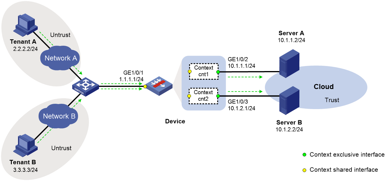
Example: Configuring contexts to act as gateways in a cloud computing center
Network configuration
As shown in Figure 5, Device is the gateway in the cloud computing center for internal information protection. The device has only one public network interface, which is GigabitEthernet 1/0/1. For Tenant A and Tenant B to independently access computing resources in the center, perform the following tasks:
· Create two contexts on the device, one is cnt1 and the other is cnt2.
· Assign interfaces to the contexts for Tenant A and Tenant B to access the center.
¡ Assign GigabitEthernet 1/0/1 to context cnt1 in shared mode and GigabitEthernet 1/0/2 to the context in exclusive mode.
¡ Assign GigabitEthernet 1/0/1 to context cnt2 in shared mode and GigabitEthernet 1/0/3 to the context in exclusive mode.
· On the shared interface GigabitEthernet 1/0/1, configure a NAT internal server for Tenant A and Tenant B to use independent public IP addresses to access Server A and Server B, respectively.
Procedure
1. Assign an IP address to GigabitEthernet 1/0/1.
<Device> system-view
[Device] interface gigabitethernet 1/0/1
[Device-GigabitEthernet1/0/1] ip address 1.1.1.1 24
[Device-GigabitEthernet1/0/1] quit
2. Create and configure context cnt1 for Tenant A:
# Create context cnt1 and configure a description for the context.
[Device] context cnt1
[Device-context-2-cnt1] description context-1
# Assign GigabitEthernet 1/0/1 to context cnt1 in shared mode.
[Device-context-2-cnt1] allocate interface gigabitethernet 1/0/1 share
# Assign GigabitEthernet 1/0/2 to context cnt1 in exclusive mode.
[Device-context-2-cnt1] allocate interface gigabitethernet 1/0/2
Configuration of the interfaces will be lost. Continue? [Y/N]:y
# Start context cnt1.
[Device-context-2-cnt1] context start
It will take some time to start the context...
Context started successfully.
[Device-context-2-cnt1] quit
# Log in to context cnt1.
[Device] switchto context cnt1
******************************************************************************
* Copyright (c) 2004-2021 New H3C Technologies Co., Ltd. All rights reserved.*
* Without the owner's prior written consent, *
* no decompiling or reverse-engineering shall be allowed. *
******************************************************************************
<H3C> system-view
# Change the system name of the context to cnt1.
[H3C] sysname cnt1
# Assign IP address 10.1.1.1/24 to interface GigabitEthernet 1/0/2.
[cnt1] interface gigabitethernet 1/0/2
[cnt1-GigabitEthernet1/0/2] ip address 10.1.1.1 24
[cnt1-GigabitEthernet1/0/2] quit
# Assign interfaces GigabitEthernet 1/0/1 and GigabitEthernet 1/0/2 to security zones Untrust and Trust, respectively.
[cnt1] security-zone name untrust
[cnt1-security-zone-Untrust] import interface gigabitethernet 1/0/1
[cnt1-security-zone-Untrust] quit
[cnt1] security-zone name trust
[cnt1-security-zone-Trust] import interface gigabitethernet 1/0/2
[cnt1-security-zone-Trust] quit
# Configure the IPv4 security policy to ensure that Tenant A can access Server A.
[cnt1] security-policy ip
[cnt1-security-policy-ip] rule name untrust-trust
[cnt1-security-policy-ip-0-untrust-trust] action pass
[cnt1-security-policy-ip-0-untrust-trust] source-zone untrust
[cnt1-security-policy-ip-0-untrust-trust] destination-zone trust
[cnt1-security-policy-ip-0-untrust-trust] source-ip-host 2.2.2.2
[cnt1-security-policy-ip-0-untrust-trust] destination-ip-host 10.1.1.2
[cnt1-security-policy-ip-0-untrust-trust] quit
[cnt1-security-policy-ip] quit
# Return to the default context from context cnt1.
[cnt1] quit
<cnt1> quit
[Device]
3. Create and configure context cnt2 for Tenant B:
# Create context cnt2 and configure a description for the context.
[Device] context cnt2
[Device-context-3-cnt2] description context-2
# Assign GigabitEthernet 1/0/1 to context cnt2 in shared mode.
[Device-context-3-cnt2] allocate interface gigabitethernet 1/0/1 share
# Assign GigabitEthernet 1/0/3 to context cnt2 in exclusive mode.
[Device-context-3-cnt2] allocate interface gigabitethernet 1/0/3
Configuration of the interfaces will be lost. Continue? [Y/N]:y
# Start context cnt2.
[Device-context-3-cnt2] context start
It will take some time to start the context...
Context started successfully.
[Device-context-3-cnt2] quit
# Log in to context cnt2.
[Device] switchto context cnt2
******************************************************************************
* Copyright (c) 2004-2021 New H3C Technologies Co., Ltd. All rights reserved.*
* Without the owner's prior written consent, *
* no decompiling or reverse-engineering shall be allowed. *
******************************************************************************
<H3C> system-view
# Change the system name of the context to cnt2.
[H3C] sysname cnt2
# Assign IP address 10.1.2.1/24 to interface GigabitEthernet 1/0/3.
[cnt2] interface gigabitethernet 1/0/3
[cnt2-GigabitEthernet1/0/3] ip address 10.1.2.1 24
[cnt2-GigabitEthernet1/0/3] quit
# Assign interfaces GigabitEthernet 1/0/1 and GigabitEthernet 1/0/3 to security zones Untrust and Trust, respectively.
[cnt2] security-zone name untrust
[cnt2-security-zone-Untrust] import interface gigabitethernet 1/0/1
[cnt2-security-zone-Untrust] quit
[cnt2] security-zone name trust
[cnt2-security-zone-Trust] import interface gigabitethernet 1/0/3
[cnt2-security-zone-Trust] quit
# Configure the IPv4 security policy to ensure that Tenant B can access Server B.
[cnt2] security-policy ip
[cnt2-security-policy-ip] rule name untrust-trust
[cnt2-security-policy-ip-0-untrust-trust] action pass
[cnt2-security-policy-ip-0-untrust-trust] source-zone untrust
[cnt2-security-policy-ip-0-untrust-trust] destination-zone trust
[cnt2-security-policy-ip-0-untrust-trust] source-ip-host 3.3.3.3
[cnt2-security-policy-ip-0-untrust-trust] destination-ip-host 10.1.2.2
[cnt2-security-policy-ip-0-untrust-trust] quit
[cnt2-security-policy-ip] quit
# Return to the default context from context cnt2.
[cnt2] quit
<cnt2> quit
[Device]
4. On GigabitEthernet 1/0/1, configure a NAT internal server to allow the external network to access Server A by using address http://1.1.1.2:8080 and access Server B by using address http://1.1.1.3:8080.
[Device] interface gigabitethernet 1/0/1
[Device-GigabitEthernet1/0/1] nat server protocol tcp global 1.1.1.2 8080 inside 10.1.1.2 http
[Device-GigabitEthernet1/0/1] nat server protocol tcp global 1.1.1.3 8080 inside 10.1.2.2 http
[Device-GigabitEthernet1/0/1] quit
Verifying the configuration
1. Verify that the contexts are created successfully and running correctly. The device has three contexts in active state.
[Device] display context
ID Name Status Description
1 Admin active DefaultContext
2 cnt1 active context-1
3 cnt2 active context-2
2. Verify that Tenant A can access Server A by using address http://1.1.1.2:8080 and Tenant B can access Server B by using address http://1.1.1.3:8080.
