- Table of Contents
- Related Documents
-
| Title | Size | Download |
|---|---|---|
| 03-Dial program configuration | 423.25 KB |
Contents
Restrictions: Hardware compatibility with dial programs
Restrictions: Licensing requirements for dial programs
Example: Configuring caller control
Configuring caller group control
Configuring a subscriber group
Configuring a subscriber group on a voice entity
Enabling private line auto ring-down
Configuring a number match mode
Example: Configuring a number match mode
Setting the maximum number of calls allowed by a voice entity
Configuring number substitution
Configuring a number substitution rule list
Applying a number substitution rule list globally
Applying a number substitution rule list to a voice entity
Applying a number substitution rule list to a voice interface
Example: Configuring number substitution
Setting the priority for a voice entity
Configuring the voice entity selection order
Configuring a number sending mode
About the number sending modes
Example: Configuring the number sending mode
Dial program configuration examples
Example: Configuring number substitution
Example: Configuring caller group control
Example: Setting the maximum number of calls
Configuring dial programs
About dial programs
Dial programs define call control policies such as caller control, number substitution, call sending, and number match policies. You can use dial programs to manage call numbers in a unified way and to customize different dial-up schemes.
Restrictions: Hardware compatibility with dial programs
|
Hardware |
Dial program compatibility |
|
MSR810, MSR810-W, MSR810-W-DB, MSR810-LM, MSR810-W-LM, MSR810-10-PoE, MSR810-LM-HK, MSR810-W-LM-HK, MSR810-LM-CNDE-SJK, MSR810-CNDE-SJK |
Yes for only number substitution |
|
MSR810-LMS, MSR810-LUS |
No |
|
MSR810-LMS-EA, MSR810-LME |
No |
|
MSR1004S-5G |
No |
|
MSR2600-6-X1, MSR2600-15-X1 |
No |
|
MSR2600-10-X1 |
Yes |
|
MSR 2630 |
Yes |
|
MSR3600-28, MSR3600-51 |
Yes |
|
MSR3600-28-SI, MSR3600-51-SI |
No |
|
MSR3600-28-X1, MSR3600-28-X1-DP, MSR3600-51-X1, MSR3600-51-X1-DP |
No |
|
MSR3610-I-DP, MSR3610-IE-DP, MSR3610-IE-ES, MSR3610-IE-EAD, MSR-EAD-AK770, MSR3610-I-IG, MSR3610-IE-IG |
No |
|
MSR3610-X1, MSR3610-X1-DP, MSR3610-X1-DC, MSR3610-X1-DP-DC, MSR3620-X1, MSR3640-X1 |
Yes |
|
MSR 3610, MSR 3620, MSR 3620-DP, MSR 3640, MSR 3660 |
Yes |
|
MSR3610-G, MSR3620-G |
No |
|
MSR3640-X1-HI |
Yes |
|
Hardware |
Dial program compatibility |
|
MSR810-W-WiNet, MSR810-LM-WiNet |
Yes for only number substitution |
|
MSR830-4LM-WiNet |
No |
|
MSR830-5BEI-WiNet, MSR830-6EI-WiNet, MSR830-10BEI-WiNet |
No |
|
MSR830-6BHI-WiNet, MSR830-10BHI-WiNet |
No |
|
MSR2600-6-WiNet |
No |
|
MSR2600-10-X1-WiNet |
Yes |
|
MSR2630-WiNet |
Yes |
|
MSR3600-28-WiNet |
Yes |
|
MSR3610-X1-WiNet |
Yes |
|
MSR3610-WiNet, MSR3620-10-WiNet, MSR3620-DP-WiNet, MSR3620-WiNet, MSR3660-WiNet |
Yes |
|
Hardware |
Dial program compatibility |
|
MSR2630-XS |
No |
|
MSR3600-28-XS |
No |
|
MSR3610-XS |
Yes |
|
MSR3620-XS |
Yes |
|
MSR3610-I-XS |
No |
|
MSR3610-IE-XS |
No |
|
MSR3620-X1-XS |
Yes |
|
MSR3640-XS |
Yes |
|
MSR3660-XS |
Yes |
|
Hardware |
Dial program compatibility |
|
MSR810-LM-GL |
Yes for number substituition |
|
MSR810-W-LM-GL |
Yes for number substituition |
|
MSR830-6EI-GL |
No |
|
MSR830-10EI-GL |
No |
|
MSR830-6HI-GL |
No |
|
MSR830-10HI-GL |
No |
|
MSR1004S-5G-GL |
No |
|
MSR2600-6-X1-GL |
No |
|
MSR3600-28-SI-GL |
No |
Restrictions: Licensing requirements for dial programs
To support dial programs, some device models require the Voice Software License. For more information, see license management in Fundamentals Configuration Guide.
Configuring caller control
About caller control
Caller control allows you to filter outgoing calls on the calling side or filter incoming calls on the called side based on calling numbers. A call can be placed only when the calling number matches a permitted calling number.
Procedure
1. Enter system view.
system-view
2. Enter voice view.
voice-setup
3. Enter dial program view.
dial-program
4. Create a voice entity and enter its view.
entity entity-number { ivr | pots | voip }
5. Configure permitted calling numbers.
caller-permit calling-string
By default, a voice entity permits all calling numbers.
The calling-string argument is in the format of { [ + ] string [ $ ] } | $. For more information about the format, see dial program commands in Voice Command Reference.
Example: Configuring caller control
Network configuration
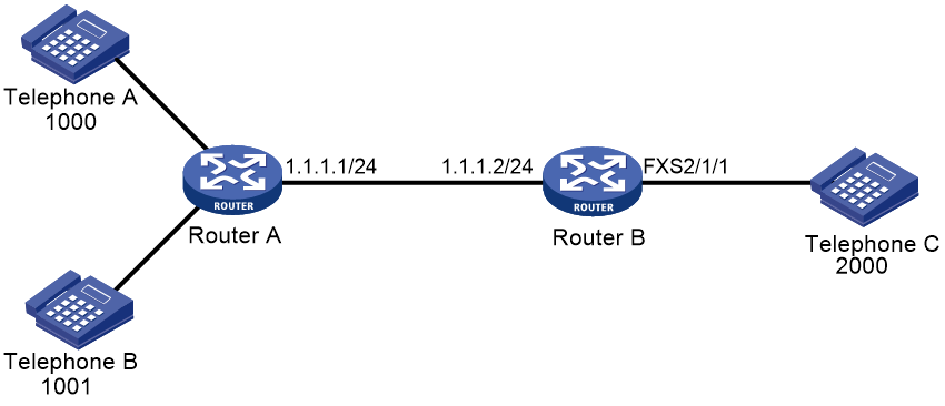
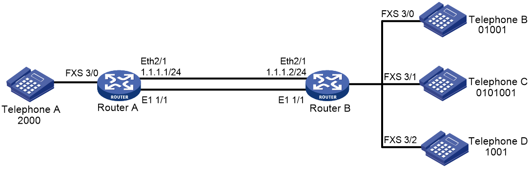
As shown in Figure 1, configure caller control to permit only the number 1000 to call the number 2000.
Procedure
You can configure caller control either on the calling side or on the called side.
· Configure caller control on the calling side.
# Enter dial program view.
<RouterA> system-view
[RouterA] voice-setup
[RouterA-voice] dial-program
# Configure VoIP entity 2000 to permit only the calling number 1000 to call the number 2000.
[RouterA-voice-dial] entity 2000 voip
[RouterA-voice-dial-entity2000] match-template 2000
[RouterA-voice-dial-entity2000] address sip ip 1.1.1.2
[RouterA-voice-dial-entity2000] caller-permit 1000$
· Configure caller control on the called side.
# Enter dial program view.
<RouterB> system-view
[RouterB] voice-setup
[RouterB-voice] dial-program
# Configure POTS entity 2000 to permit only the calling number 1000 to call the number 2000.
[RouterB-voice-dial] entity 2000 pots
[RouterB-voice-dial-entity2000] match-template 2000
[RouterB-voice-dial-entity2000] caller-permit 1000$
[RouterB-voice-dial-entity2000] line 2/1/1
Configuring caller group control
About caller group control
Caller group control allows you to filter outgoing calls on the calling side or filter incoming calls on the called side based on caller groups. Caller group control is often used on the calling side.
A caller group references a subscriber group that defines the matching calling numbers. After you bind a caller group to a voice entity on the calling side, only the permitted calling numbers can call the called numbers on the voice entity.
Configuring a subscriber group
1. Enter system view.
system-view
2. Enter voice view.
voice-setup
3. Enter dial program view.
dial-program
4. Create a subscriber group and enter its view.
subscriber-group group-id
You can create a maximum of 10 subscriber groups.
5. (Optional.) Configure a description for the subscriber group.
description text
By default, no description is configured for a subscriber group.
6. Configure a match template for the subscriber group.
match-template match-string
By default, no match templates are configured for a subscriber group.
You can configure multiple match templates for a subscriber group.
Configuring a subscriber group on a voice entity
1. Enter system view.
system-view
2. Enter voice view.
voice-setup
3. Enter dial program view.
dial-program
4. Create a voice entity and enter its view.
entity entity-number { ivr | pots | voip }
5. Configure the voice entity to permit or deny the calling numbers in the specified subscriber group.
caller-group { deny | permit } group-id
By default, all calling numbers are permitted.
Enabling private line auto ring-down
About this task
The private line auto ring-down (PLAR) feature enables a subscriber line to automatically call the specified called number when the phone goes off-hook.
Procedure
1. Enter system view.
system-view
2. Enter voice interface view.
subscriber-line line-number
3. Enable PLAR for the specified called number.
private-line string
By default, PLAR is disabled.
Configuring a number match mode
About number match modes
Two number match modes are available: longest match and shortest match.
Suppose you have configured match-template 0106688 on a voice entity and match-template 01066880011 on another voice entity.
When a subscriber dials 01066880011, the following rules apply:
· If shortest match is used, the router matches and calls the number 0106688.
· If longest match is used, the router matches and calls the number 01066880011.
When a subscriber dials 0106688, the following rules apply:
· If shortest match is used, the router matches and calls the number 0106688.
· If longest match is used, the router waits until the dial timer expires. Then the router matches the received number against match templates. If a match is found, the router calls the matching number. If no match is found, the router releases the call.
You can configure a terminator that identifies the end of a number. For example, suppose the terminator is the pound sign #. When a subscriber dials 0106688#, the router immediately matches the number 0106688 with match templates regardless of whether or not longest match is used. If a match is found, the router calls the matching number.
Procedure
1. Enter system view.
system-view
2. Enter voice view.
voice-setup
3. Enter dial program view.
dial-program
4. Configure a number match mode.
number-match { longest | shortest }
By default, shortest match is used.
5. (Optional.) Configure a terminator.
terminator character
By default, no terminator is configured.
Example: Configuring a number match mode
Network configuration
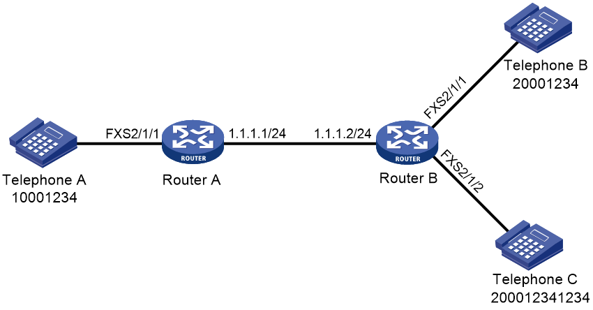
As shown in Figure 2, configure number match modes for calls from Telephone A to Telephones B and C.
Configuring shortest match
1. Configure Router A:
# Enter dial program view.
<RouterA> system-view
[RouterA] voice-setup
[RouterA-voice] dial-program
# Configure POTS entity 1000.
[RouterA-voice-dial] entity 1000 pots
[RouterA-voice-dial-entity1000] match-template 10001234$
[RouterA-voice-dial-entity1000] line 2/1/1
[RouterA-voice-dial-entity1000] quit
# Configure VoIP entity 2000 and VoIP entity 2001.
[RouterA-voice-dial] entity2000 voip
[RouterA-voice-dial-entity2000] match-template 20001234$
[RouterA-voice-dial-entity2000] address ip 1.1.1.2
[RouterA-voice-dial-entity2000] quit
[RouterA-voice-dial] entity2001 voip
[RouterA-voice-dial-entity2001] match-template 200012341234$
[RouterA-voice-dial-entity2001] address ip 1.1.1.2
[RouterA-voice-dial-entity2001] quit
2. Configure Router B:
# Enter dial program view.
<RouterB> system-view
[RouterB] voice-setup
[RouterB-voice] dial-program
# Configure POTS entity 2000 and POTS entity 2001.
[RouterB-voice-dial] entity 2000 pots
[RouterB-voice-dial-entity2000] match-template 20001234$
[RouterB-voice-dial-entity2000] line 2/1/1
[RouterB-voice-dial-entity2000] quit
[RouterB-voice-dial] entity2001 pots
[RouterB-voice-dial-entity2001] match-template 200012341234$
[RouterB-voice-dial-entity2001] line 2/1/2
After you dial number 20001234 at Telephone A, the number matches VoIP entity 2000 and Telephone B rings because the device uses shortest match mode by default.
Configuring longest match
# Configure the longest match mode on Router A.
[RouterA-voice-dial] number-match longest
After you dial number 20001234 at Telephone A and waits for a period of time, the number matches VoIP entity 2000 and Telephone B rings. If you dial 1234 during the waiting period (the dialed number is 200012341234), the number matches VoIP entity 2001 and Telephone C rings.
Configuring a terminator
# Configure the terminator # on Router A.
[RouterA-voice-dial] terminator #
After you dial 20001234# at Telephone A, the number immediately matches VoIP entity 2000 and Telephone B rings.
Setting the maximum number of calls allowed by a voice entity
About this task
You can limit the maximum number of calls allowed by a voice entity. The device stops establishing new calls when the limit is reached.
Procedure
1. Enter system view.
system-view
2. Enter voice view.
voice-setup
3. Enter dial program view.
dial-program
4. Enter voice entity view.
entity entity-number { ivr | pots | voip }
5. Set the maximum number of calls allowed by the voice entity.
max-conn max-number
By default, the number of calls allowed by a voice entity is not limited.
Configuring number substitution
About number substitution
A number substitution rule replaces a matching number with another number. You can configure number substation rules and then apply these rules globally or to voice entities and voice interfaces.
Number substitution process
A number substitution process is as follows:
1. The router first matches a number against the preferred number substitution rule. If they match, the router replaces the number based on the preferred rule.
2. If the match fails, the router matches the number against other number substitution rules in sequence. Once a rule is matched, the router replaces the number based on the matching rule and stops matching other number substitution rules.
If a number matches multiple types of substitution rules, the device performs substitution on the number in the sequence of global substitution, voice entity substitution, and voice interface substitution. For each type, the router performs only one substitution.
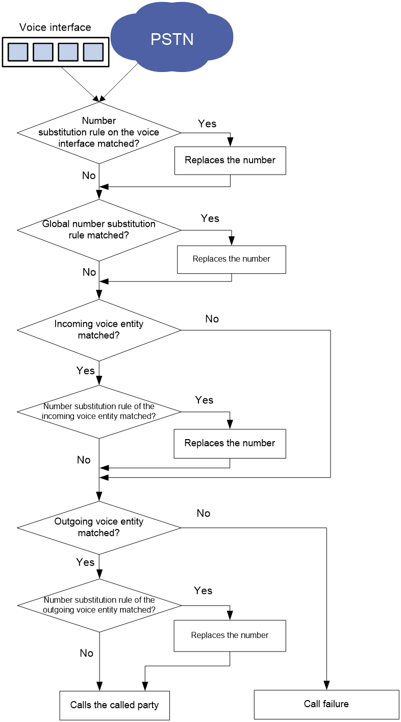
Number substitution on the calling router
As shown Figure 3, the calling router performs number substitution for a number as follows:
1. The router receives a call on a voice interface.
2. The router matches the calling or called number of the call against different types of number substitution rules in the following order:
a. Rules on the voice entity.
b. Global rules.
c. Rules on the incoming voice entity (if the number matches one).
d. Rules on the outgoing voice entity (if the number matches one).
If a match is found for a rule type, the router replaces the number, and matches the new number against the next rule type. If no match is found for a rule type, the router keeps matching the number against the next rule type. This matching process continues until all rule types are matched. For each rule type, the router performs only one number substitution.
3. The router places the call to the called party.
Figure 3 Flow chart for number substitution on the calling router
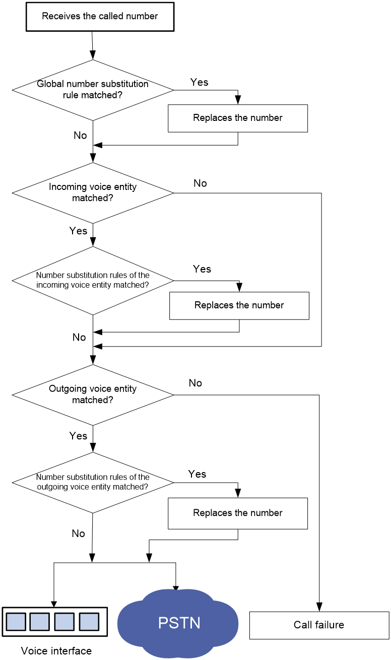
Number substitution on the called router
As shown Figure 4, the called router performs number substitution for a number as follows:
1. The router receives a call.
2. The router matches the called number against different types of number substitution rules in the following order:
a. Global rules.
b. Rules on the incoming voice entity (if the number matches one).
c. Rules on the outgoing voice entity (if the number matches one).
If a match is found for a rule type, the router replaces the number, and matches the new number against the next rule type. If no match is found for a rule type, the router keeps matching the number against the next rule type. The matching process continues until all rule types are matched. For each type, the router performs only one number substitution.
3. The router calls the called number if the called party is on a local voice interface, or initiates a call to the PSTN if the called party is in the PSTN.
Figure 4 Flow chart for number substitution on the called router
Configuring a number substitution rule list
system-view
2. Enter voice view.
voice-setup
3. Enter dial program view.
dial-program
4. Create a number substitution rule list and enter its view.
number-substitute list-number
5. Configure a dot-match rule.
dot-match { end-only | left-right | right-left }
By default, the dot match rule is end-only.
6. Configure a number substitution rule.
rule id input-template output-template [ number-type input-number-type output-number-type | numbering-plan input-numbering-plan output-numbering-plan ] *
By default, no number substitution rules are configured.
7. (Optional.) Configure the preferred number substitution rule.
first-rule id
By default, no preferred number substitution rule is configured.
Applying a number substitution rule list globally
1. Enter system view.
system-view
2. Enter voice view.
voice-setup
3. Enter dial program view.
dial-program
4. Apply a number substitution rule list to the calling or called number of incoming or outgoing calls.
substitute { incoming-call | outgoing-call } { called | calling } list-number
By default, no number substitution rule list is applied globally. No number substitution is performed.
Applying a number substitution rule list to a voice entity
1. Enter system view.
system-view
2. Enter voice view.
voice-setup
3. Enter dial program view.
dial-program
4. Enter voice entity view.
entity entity-number { ivr | pots |voip }
5. Apply a number substitution rule list to the voice entity.
substitute { called | calling } list-number
By default, no number substitution rule list is applied to a voice entity. The voice entity does not perform number substitution.
Applying a number substitution rule list to a voice interface
1. Enter system view.
system-view
2. Enter voice interface view.
subscriber-line line-number
3. Apply a number substitution rule list to the voice interface.
substitute { called | calling } list-number
By default, no number substitution rule list is applied to a voice interface. The voice interface does not perform number substitution.
Example: Configuring number substitution
Network configuration
Configure global number substitution, voice entity number substitution, and voice interface number substitution to replace the called numbers.
Figure 5 Network diagram

Configuring global number substitution
# Create number substitution rule list 1 and add a rule to the list.
<RouterA> system-view
[RouterA] voice-setup
[RouterA-voice] dial-program
[RouterA-voice-dial] number-substitute 1
[RouterA-voice-dial-substitute1] rule 0 ^010....$ ....
[RouterA-voice-dial-substitute1] quit
# Configure the destination address as 1.1.1.2 and the called number as 1001 for VoIP entity 1001.
[RouterA-voice-dial] entity 1001 voip
[RouterA-voice-dial-entity1001] address sip ip 1.1.1.2
[RouterA-voice-dial-entity1001] match-template 1001
[RouterA-voice-dial-entity1001] quit
# Apply number substitution rule list 1 to the called number of outgoing calls.
[RouterA-voice-dial] substitute outgoing-call called 1
When you use Telephone A to call number 0101001, Router A replaces 0101001 with 1001 and sends the call to the destination address 1.1.1.2. Then Telephone B rings.
Configuring voice entity number substitution
# Create number substitution rule list 1 and add a rule to the list.
<RouterA> system-view
[RouterA] voice-setup
[RouterA-voice] dial-program
[RouterA-voice-dial] number-substitute 1
[RouterA-voice-dial-substitute1] rule 0 ^010....$ ....
[RouterA-voice-dial-substitute1] quit
# Configure the destination address as 1.1.1.2 and the called number as 0101001 for VoIP entity 1001.
[RouterA-voice-dial] entity 1001 voip
[RouterA-voice-dial-entity1001] address sip ip 1.1.1.2
[RouterA-voice-dial-entity1001] match-template 0101001
# Apply number substitution rule list 1 to the called number on VoIP entity 1001.
[RouterA-voice-dial-entity1001] substitute called 1
When you use Telephone A to call number 0101001, VoIP entity 1001 replaces 0101001 with 1001 and sends the call to the destination address 1.1.1.2. Then Telephone B rings.
Configuring voice interface number substitution
# Create number substitution rule list 1 and add a rule to the list.
<RouterA> system-view
[RouterA] voice-setup
[RouterA-voice] dial-program
[RouterA-voice-dial] number-substitute 1
[RouterA-voice-dial-substitute1] rule 0 ^010....$ ....
[RouterA-voice-dial-substitute1] quit
# Configure the destination address as 1.1.1.2 and the called number as 1001 for VoIP entity 1001.
[RouterA-voice-dial] entity 1001 voip
[RouterA-voice-dial-entity1001] address sip ip 1.1.1.2
[RouterA-voice-dial-entity1001] match-template 1001
[RouterA-voice-dial-entity1001] quit
[RouterA-voice-dial] quit
[RouterA-voice] quit
# Apply number substitution rule list 1 to the called number on FXS interface 2/1/1.
[RouterA] subscriber-line 2/1/1
[RouterA-voice-line2/1/1] substitute called 1
When you use Telephone A to call number 0101001, FXS interface 2/1/1 replaces 0101001 with 1001 and sends the call to the destination address 1.1.1.2. Then Telephone B rings.
Setting the priority for a voice entity
About this task
If a number matches multiple voice entities, the router selects the voice entity with the highest priority.
Procedure
1. Enter system view.
system-view
2. Enter voice view.
voice-setup
3. Enter dial program view.
dial-program
4. Enter voice entity view.
entity entity-number { ivr | pots | voip }
5. Set the priority for the voice entity.
priority priority
By default, the priority for a voice entity is 0.
Configuring the voice entity selection order
About this task
If a number matches multiple voice entities, the router selects a voice entity based on the configured selection order.
Procedure
1. Enter system view.
system-view
2. Enter voice view.
voice-setup
3. Enter dial program view.
dial-program
4. Configure a voice entity selection order.
entity hunt hunt-number
The default hunt-number is 0, which specifies longest match, voice entity priority, and random selection.
Configuring a number sending mode
About the number sending modes
The number sending mode controls how the originating router sends a called number. The router supports the following number sending modes:
· Sends the least significant digits of a called number. The number of the least significant digits is specified by using the send-number digit-number command.
· Sends all the digits of a called number.
· Sends a truncated called number. When the match-template command configured for a voice entity contains dots (.), only the digits that match the dots are sent.
Procedure
1. Enter system view.
system-view
2. Enter voice view.
voice-setup
3. Enter dial program view.
dial-program
4. Enter POTS voice entity view.
entity entity-number pots
5. Configure a number sending mode.
send-number { digit-number | all | truncate }
By default, the truncate mode is used.
Example: Configuring the number sending mode
Network configuration
As shown in Figure 6, Router A and Router B connect to each other through an IP link and an E1 link. The telephones at two sides call each other through the E1 link. Configure number sending modes to achieve different call policies.
Procedure
1. Configure Router A:
# Configure a timeslot set using R2 signaling for controller E1 2/4/1.
<RouterA> system-view
[RouterA] controller e1 2/4/1
[RouterA-E1 2/4/1] timeslot-set 0 timeslot-list 1-31 signal r2
[RouterA-E1 2/4/1] quit
[RouterA] voice-setup
[RouterA-voice] dial-program
# Configure a match template to match 010….$ for POTS entity 1001 and bind line 2/4/1:0 to the entity.
[RouterA-voice-dial] entity 1001 pots
[RouterA-voice-dial-entity1001] match-template 010....$
[RouterA-voice-dial-entity1001] line 2/4/1:0
# Configure a local number 2000 for POTS entity 2000, and bind line 2/1/1 to the entity.
[RouterA-voice-dial] entity 2000 pots
[RouterA-voice-dial-entity2000] match-template 2000
[RouterA-voice-dial-entity2000] line 2/1/1
2. Configure Router B:
# Configure a timeslot set using R2 signaling for controller E1 2/4/1.
<RouterB> system-view
[RouterB] controller e1 2/4/1
[RouterB-E1 2/4/1] timeslot-set 0 timeslot-list 1-31 signal r2
[RouterB-E1 2/4/1] quit
# Configure a local number 01001 for POTS entity 1002, and bind line 2/1/1 to the entity.
[RouterB] voice-setup
[RouterB-voice] dial-program
[RouterB] voice-setup
[RouterB-voice] dial-program
[RouterB-voice-dial] entity 1002 pots
[RouterB-voice-dial-entity1002] match-template 01001
[RouterB-voice-dial-entity1002] line 2/1/1
[RouterB-voice-dial-entity1002] quit
# Configure a local number 0101001 for POTS entity 0101001, and bind line 2/1/2 to the entity.
[RouterB-voice-dial] entity 0101001 pots
[RouterB-voice-dial-entity101001] match-template 0101001
[RouterB-voice-dial-entity101001] line 2/1/2
[RouterB-voice-dial-entity101001] quit
# Configure a local number 1001 for POTS entity 1001, and bind line 2/1/3 to the entity.
[RouterB-voice-dial] entity 1001 pots
[RouterB-voice-dial-entity1001] match-template 1001
[RouterB-voice-dial-entity1001] line 2/1/3
[RouterB-voice-dial-entity1001] quit
3. Configuring number sending modes on Router A:
¡ Configure Router A to send the five least significant digits of a called number.
[RouterA-voice-dial-entity1001] send-number 5
If you use Telephone A to call 0101001, Router A sends the called number 01001, which are the five least significant digits. Then Telephone B rings.
¡ Configure Router A to send all the digits of a called number.
[RouterA-voice-dial-entity1001] send-number all
If you use Telephone A to call 0101001, Router A sends the complete called number 0101001. Then Telephone C rings.
¡ Configure Router A to send a truncated called number.
[RouterA-voice-dial-entity1001] send-number truncate
If you use Telephone A to call 0101001, Router A sends the called number 1001, which match the dots in "010….$". Then Telephone D rings.
Configuring a dial prefix
About this task
After you configure a dial prefix, the router adds the prefix before each called number. If the called number exceeds 31 digits, the router sends only the first 31 digits.
Procedure
1. Enter system view.
system-view
2. Enter voice view.
voice-setup
3. Enter dial program view.
dial-program
4. Enter POTS entity view.
entity entity-number pots
5. Configure a dial prefix.
dial-prefix string
By default, no dial prefix is configured.
Dial program configuration examples
Example: Configuring number substitution
Network configuration
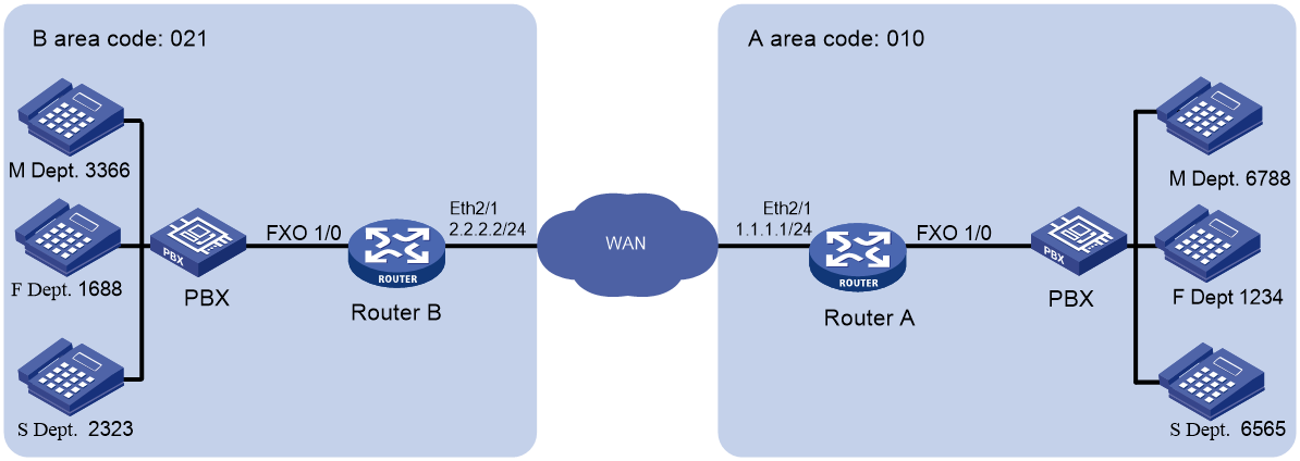
As shown in Figure 7, configure number substitution on the routers so departments in different areas can call each other by using the area code of the destination area plus a four-digit local number.
For example, to use phone 1688 of the F department in area B to call phone 6788 of the M department in area A, dial the number 0103366. The sequence 3366 is the number of the M department in area B.
On phone 6788, the calling number 1688 is displayed as 0211234, which is the area code of area A plus the number of the F department in area A.
Procedure
The following provides the number substitution configuration only for calls from area B to area A.
1. Configure Router B:
# Create number substitution rule list 21101 and add rules to the list.
<RouterB> system-view
[RouterB] voice-setup
[RouterB-voice] dial-program
[RouterB-voice-dial] number-substitute 21101
[RouterB-voice-dial-substitute21101] rule 1 ^0101688$ 0001
[RouterB-voice-dial-substitute21101] rule 2 ^0103366$ 0002
[RouterB-voice-dial-substitute21101] rule 3 ^0102323$ 0003
[RouterB-voice-dial-substitute21101] quit
# Create number substitution rule list 21102 and add rules to the list.
[RouterB-voice-dial] number-substitute 21102
[RouterB-voice-dial-substitute21102] rule 1 ^1688$ 0210001
[RouterB-voice-dial-substitute21102] rule 2 ^3366$ 0210002
[RouterB-voice-dial-substitute21102] rule 3 ^2323$ 0210003
[RouterB-voice-dial-substitute21102] quit
# Configure the match template 010.... to match called numbers, and set the destination IP address as 1.1.1.1 for VoIP entity 10.
[RouterB-voice-dial] entity 10 voip
[RouterB-voice-dial-entity10] match-template 010....
[RouterB-voice-dial-entity10] address sip ip 1.1.1.1
# Apply the number substitution rule list 21101 to called numbers on VoIP entity 10. This will change the called numbers 0101688, 0103366, and 0102323 into 0001, 0002, and 0003 respectively.
[RouterB-voice-dial-entity10] substitute called 21101
# Apply the number substitution rule list 21102 to calling numbers on VoIP entity 10. This will change the calling numbers 1688, 3366, and 2323 into 0210001, 0210002, and 0210003 respectively.
[RouterB-voice-dial-entity10] substitute calling 21102
2. Configure Router A:
# Create number substitution rule list 101 and add rules to the list.
<RouterA> system-view
[RouterA] voice-setup
[RouterA-voice] dial-program
[RouterA-voice-dial] number-substitute 101
[RouterA-voice-dial-substitute101] rule 1 ^0001$ 1234
[RouterA-voice-dial-substitute101] rule 2 ^0002$ 6788
[RouterA-voice-dial-substitute101] rule 3 ^0003$ 6565
[RouterA-voice-dial-substitute101] quit
# Create number substitution rule list 102 and add rules to the list.
[RouterA-voice-dial] number-substitute 102
[RouterA-voice-dial-substitute102] dot-match left-right
[RouterA-voice-dial-substitute102] rule 1 ^...0001$ ...1234
[RouterA-voice-dial-substitute102] rule 2 ^...0002$ ...6788
[RouterA-voice-dial-substitute102] rule 3 ^...0003$ ...6565
[RouterA-voice-dial-substitute102] quit
# Apply the number substitution rule list 101 to the called numbers of incoming calls. This will change the called numbers 0001, 0002, and 0003 into 1234, 6788, and 6565 respectively.
[RouterA-voice-dial] substitute incoming-call called 101
# Apply the number substitution rule list 102 to the calling numbers of incoming calls. This will change the called numbers 0210001, 0210002, and 0210003 into 0211234, 0216788, and 0216565 respectively.
[RouterA-voice-dial] substitute incoming-call calling 102
# Configure the match template …. for POTS entity 1010, bind line 2/1/1 to the entity, and configure the entity to send all the digits of a called number.
[RouterA-voice-dial] entity 1010 pots
[RouterA-voice-dial-entity1010] match-template ....
[RouterA-voice-dial-entity1010] line 2/1/1
[RouterA-voice-dial-entity1010] send-number all
Verifying the configuration
# Use phone 1688 to dial the number 0103366 to verify that phone 6788 rings and the displayed calling number is 0211234.
During the calling process, Router B changes the calling number 1688 into 0210001 and changes the called number 0103366 into 0002. Then Router A changes 0210001 into 0211234 and changes 0002 into 6788.
Example: Configuring caller group control
Network configuration
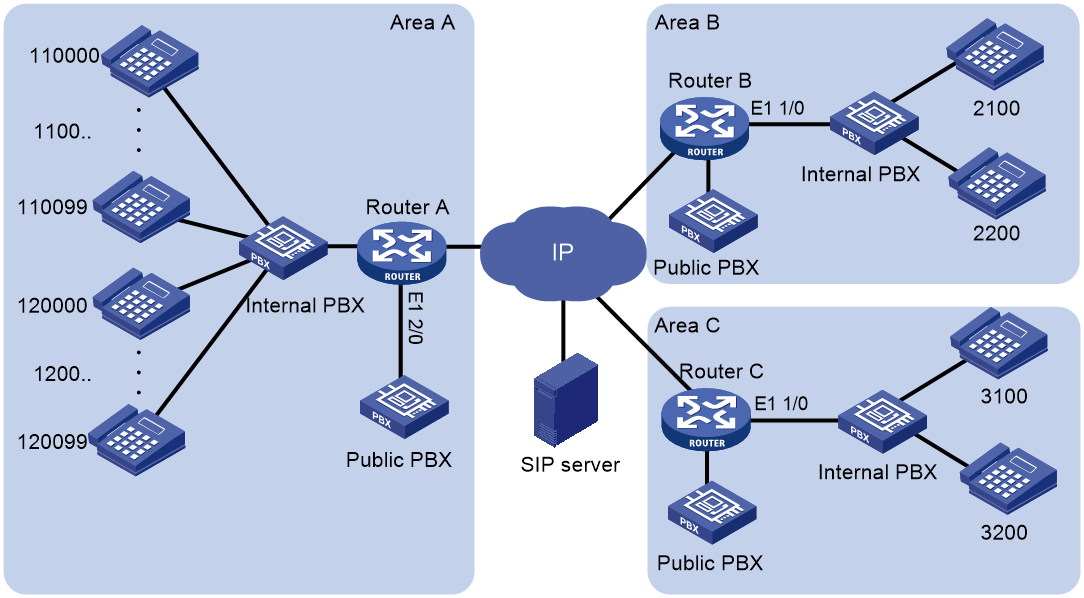
As shown in Figure 8, areas A, B, and C call each other through the SIP server. Configure caller group control on Router A so when the SIP server fails, the areas call each other though the public PBXs in PSTN as follows:
· The phone numbers starting with 1100 in area A can only call the phone numbers in area B.
· The phone numbers starting with 1200 in area A can call the phone numbers both in area B and area C.
Procedure
This example does not provide SIP server and digital voice interface configurations. For information about configuring SIP servers and digital voice interfaces, see "Configuring SIP" and "Configuring voice interfaces."
1. Configure Router A:
# Configure subscriber group 1 that matches calling numbers starting with 1100 and configure subscriber group 2 that matches calling numbers starting with 1200.
<RouterA> system-view
[RouterA] voice-setup
[RouterA-voice] dial-program
[RouterA-voice-dial] subscriber-group 1
[RouterA-voice-dial-group1] match-template 1100..
[RouterA-voice-dial-group1] quit
[RouterA-voice-dial] subscriber-group 2
[RouterA-voice-dial-group2] match-template 1200..
[RouterA-voice-dial-group2] quit
# Configure VoIP entity 2000 to use the SIP proxy server to find call destination addresses and to match called numbers in area B.
[RouterA-voice-dial] entity 2000 voip
[RouterA-voice-dial-entity2000] address sip proxy
[RouterA-voice-dial-entity2000] match-template 2...
[RouterA-voice-dial-entity2000] quit
# Configure VoIP entity 3000 to use the SIP proxy server to find call destination addresses and to match called numbers in area C.
[RouterA-voice-dial] entity 3000 voip
[RouterA-voice-dial-entity3000] address sip proxy
[RouterA-voice-dial-entity3000] match-template 3...
[RouterA-voice-dial-entity3000] quit
# Configure a caller group to permit subscriber groups 1 and 2 on POTS entity 2100 so the phone numbers starting with 1100 or 1200 in area A can call the phone numbers in area B.
[RouterA-voice-dial] entity 2100 pots
[RouterA-voice-dial-entity2100] line 2/0:15
[RouterA-voice-dial-entity2100] send-number all
[RouterA-voice-dial-entity2100] match-template 2...
[RouterA-voice-dial-entity2100] caller-group permit 1
[RouterA-voice-dial-entity2100] caller-group permit 2
[RouterA-voice-dial-entity2100] quit
# Configure a caller group to permit subscriber group 2 on POTS entity 3100 so the phone numbers starting with 1200 in area A can call the phone numbers in area C.
[RouterA-voice-dial] entity 3100 pots
[RouterA-voice-dial-entity3100] line 2/0:15
[RouterA-voice-dial-entity3100] send-number all
[RouterA-voice-dial-entity3100] match-template 3...
[RouterA-voice-dial-entity3100] caller-group permit 2
[RouterA-voice-dial] quit
# Configure POTS entity 2100 to match local numbers and bind line 2/1/1:15 to the entity.
[RouterA-voice-dial] entity 2100 pots
[RouterA-voice-dial-entity2100] line 2/1/1:15
[RouterA-voice-dial-entity2100] send-number all
[RouterA-voice-dial-entity2100] match-template 1.....
2. Configure Router B:
# Configure POTS entity 2100 to match local numbers and bind line 2/1/1:15 to the entity.
<RouterB> system-view
[RouterB] voice-setup
[RouterB-voice] dial-program
[RouterB-voice-dial] entity 2100 pots
[RouterB-voice-dial-entity2100] line 2/1/1:15
[RouterB-voice-dial-entity2100] send-number all
[RouterB-voice-dial-entity2100] match-template 2...
3. Configure Router C:
# Configure POTS entity 3100 to match local numbers and bind line 2/1/1:15 to the entity.
<RouterC> system-view
[RouterC] voice-setup
[RouterC-voice] dial-program
[RouterC-voice-dial] entity 3100 pots
[RouterC-voice-dial-entity3100] line 2/1/1:15
[RouterC-voice-dial-entity3100] send-number all
[RouterC-voice-dial-entity3100] match-template 3...
Verifying the configuration
# Place calls to verify that the phone numbers starting with 1100 in area A can only call the phone numbers in area B.
# Place calls to verify that the phone numbers starting with 1200 in area A can call the phone numbers both in area B and area C.
Example: Setting the maximum number of calls
Network configuration
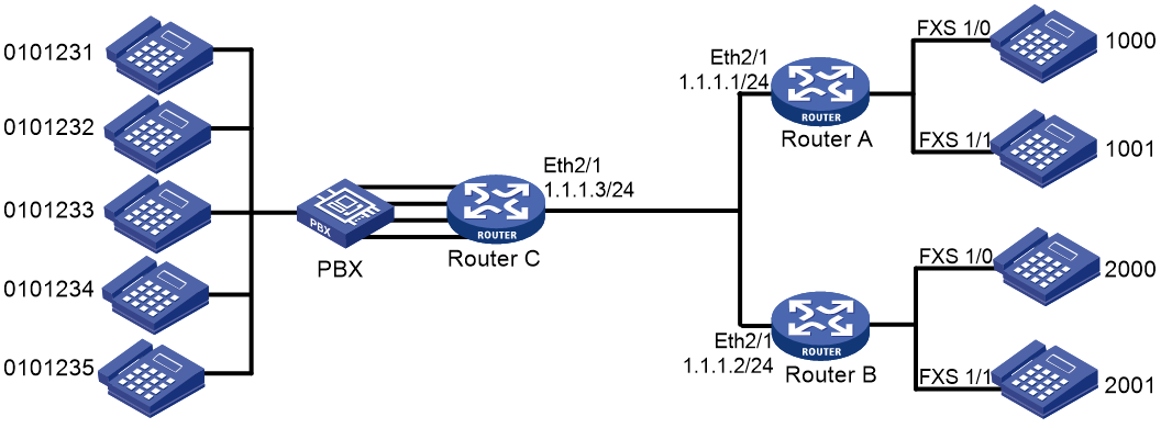
As shown in Figure 9, set the maximum number of calls placed from Router A and Router B to Router C.
Procedure
1. Configure Router A:
# Configure the called number template as 010…. for VoIP entity 2000, and configure the destination IP address as 1.1.1.3.
<RouterA> system-view
[RouterA] voice-setup
[RouterA-voice] dial-program
[RouterA-voice-dial] entity 2000 voip
[RouterA-voice-dial-entity2000] match-template 010....
[RouterA-voice-dial-entity2000] address sip ip 1.1.1.3
[RouterA-voice-dial-entity2000] quit
# Configure the local number as 1000 for POTS entity 1000, and bind FXS interface line 2/1/1 to the POTS entity.
[RouterA-voice-dial] entity 1000 pots
[RouterA-voice-dial-entity1000] match-template 1000
[RouterA-voice-dial-entity1000] line 2/1/1
[RouterA-voice-dial-entity1000] quit
# Configure the local number as 1001 for POTS entity 1001, and bind FXS interface line 1/1 to the POTS entity.
[RouterA-voice-dial] entity 1001 pots
[RouterA-voice-dial-entity1001] match-template 1001
[RouterA-voice-dial-entity1001] line 1/1
[RouterA-voice-dial-entity1001] quit
# Configure the maximum number of calls allowed by VoIP entity 2000 as 2.
[RouterA-voice-dial] entity 2000 voip
[RouterA-voice-dial-entity2000] max-conn 2
2. Configure Router B:
# Configure the called number template as 010…. for VoIP entity 1000, and configure the destination IP address as 1.1.1.3.
<RouterB> system-view
[RouterB] voice-setup
[RouterB-voice] dial-program
[RouterB-voice-dial] entity 1000 voip
[RouterB-voice-dial-entity1000] match-template 010....
[RouterB-voice-dial-entity1000] address sip ip 1.1.1.3
[RouterB-voice-dial-entity1000] quit
# Configure the local number as 2000 for POTS entity 2000, and bind FXS interface line 2/1/1 to the POTS entity.
[RouterB-voice-dial] entity 2000 pots
[RouterB-voice-dial-entity2000] match-template 2000
[RouterB-voice-dial-entity2000] line 2/1/1
[RouterB-voice-dial-entity2000] quit
# Configure the local number as 2001 for POTS entity 2001, and bind FXS interface line 1/1 to the POTS entity.
[RouterB-voice-dial] entity 2001 pots
[RouterB-voice-dial-entity2001] match-template 2001
[RouterB-voice-dial-entity2001] line 1/1
[RouterB-voice-dial-entity2001] quit
# Configure the maximum number of calls allowed by VoIP entity 1000 as 2.
[RouterB-voice-dial] entity 1000 voip
[RouterB-voice-dial-entity1000] max-conn 2
3. Configure Router C:
# Configure the local number template as 010…. for POTS entity 1000, bind FXO interface line 5/0 to the POTS entity, and configure the number sending mode as all.
<RouterC> system-view
[RouterC-voice-dial] entity 1000 pots
[RouterC-voice-dial-entity1000] match-template 010....
[RouterC-voice-dial-entity1000] line 5/0
[RouterC-voice-dial-entity1000] send-number all
[RouterC-voice-dial-entity1000] quit
# Configure the local number template as 010…. for POTS entity 1001, bind FXO interface line 5/1 to the POTS entity, and configure the number sending mode as all.
[RouterC-voice-dial] entity 1001 pots
[RouterC-voice-dial-entity1001] match-template 010....
[RouterC-voice-dial-entity1001] line 5/1
[RouterC-voice-dial-entity1001] send-number all
[RouterC-voice-dial-entity1001] quit
# Configure the local number template as 010…. for POTS entity 1002, bind FXO interface line 5/2 to the POTS entity, and configure the number sending mode as all.
[RouterC-voice-dial] entity 1002 pots
[RouterC-voice-dial-entity1002] match-template 010....
[RouterC-voice-dial-entity1002] line 5/2
[RouterC-voice-dial-entity1002] send-number all
[RouterC-voice-dial-entity1002] quit
# Configure the local number template as 010…. for POTS entity 1003, bind FXO interface line 5/3 to the POTS entity, and configure the number sending mode as all.
[RouterC-voice-dial] entity 1003 pots
[RouterC-voice-dial-entity1003] match-template 010....
[RouterC-voice-dial-entity1003] line 5/3
[RouterC-voice-dial-entity1003] send-number all
Verifying the configuration
# Initiate the maximum number of concurrent calls, for example, from 1000 and 1001. (Details not shown.)
# Initiate a call while the above calls are present to verify that the call is rejected. (Details not shown.)
