- Table of Contents
- Related Documents
-
| Title | Size | Download |
|---|---|---|
| 01-Voice interface configuration | 874.00 KB |
Configuring analog voice interfaces
Restrictions: Hardware compatibility with analog voice interfaces
Configuring basic settings for analog voice interfaces
Configuring the description for an analog voice interface
Bring up an analog voice interface
Restoring the default settings for an analog voice interface
Configuring call progress tones
Setting the electrical impedance
Configuring the packet loss compensation mode
Configuring an FXS interface to send LCFO signals
Configuring busy tone detection
Configuring ring detection parameters
Setting the electrical impedance
Configuring the packet loss compensation mode
Binding an FXS interface to an FXO interface
Configuring a start mode for E&M signaling
Configuring the E&M non-signaling mode
Enabling E&M control signals pass-through
Configuring the output gain of SLIC chip
Configuring DTMF tone detection
Adjusting parameters for analog voice interfaces
Enabling the comfortable noise feature
Display and maintenance commands for analog voice interfaces
Analog voice interface configuration examples
Example: Configuring two-dial for FXO interfaces
Example: Configuring PLAR for FXO interfaces
Example: Configuring E&M interfaces
Example: Configuring E&M non-signaling mode
Example: Configuring FXS&FXO 1:1 bindings
Configuring digital voice interfaces
About digital voice interfaces
Restrictions: Hardware compatibility with digital voice interfaces
Digital voice interface tasks at a glance
E1 and T1 interface tasks at a glance
BSV interface tasks at a glance
Configuring basic settings for digital voice interfaces
Configuring the description for a digital voice interface
Bring up a digital voice interface
Restoring the default settings for a digital voice interface
Configuring basic parameters for an E1 interface
Configuring a TDM clock source
Configuring parameters for an E1 interface
Restoring the default settings for an E1 interface
Configuring basic parameters for a T1 interface
Configuring a TDM clock source
Configuring parameters for a T1 interface
Restoring the default settings for a T1 interface
Restrictions and guidelines for BSV interface configuration
Configuring basic parameters for a BSV interface
Restoring the default settings for a BSV interface
Configuring a logical digital voice interface
Configuring basic R2 signaling parameters
Configuring R2 digital line signaling
Configuring R2 interregister signaling
Binding a digital voice interface to a POTS entity
Enabling the device to treat DISCONNECT messages with PI 8 as standard DISCONNECT messages
Adjusting parameters for digital voice interfaces
Enabling the comfortable noise feature
Display and maintenance commands for digital voice interfaces
Digital voice interface configuration examples
Example: Configuring R2 signaling
Example: Configuring E1 DSS1 signaling
Example: Configuring BSV DSS1 signaling
Configuring analog voice interfaces
About analog voice interfaces
Analog voice interfaces include FXS, FXO, and E&M interfaces.
FXS interface
A Foreign Exchange Station (FXS) interface connects to a standard telephone, fax machine, or a Private Branch Exchange (PBX) through an RJ-11 connector and a telephone cable. It provides ring, voltage, and dial tone based on level changes on the Tip/Ring line. An FXS interface can only connect to an FXO interface.
FXO interface
A foreign exchange office (FXO) interface connects to a PBX through an RJ-11 connector and a telephone cable. It provides ring, voltage, and dial tone based on level changes on the Tip/Ring line. An FXO interface can only connect to an FXS interface.
E&M interface
An ear & mouth or rEceive & transMit (E&M) interface is a common trunk line that connects to a PBX through an RJ-48 connector. The E&M interface supports E&M signaling. The E signaling receives signals from the peer, and the M signaling sends signals to the peer. An E&M interface can only connect to an E&M interface.
Restrictions: Hardware compatibility with analog voice interfaces
|
Hardware |
Analog voice interface compatibility |
|
MSR810, MSR810-W, MSR810-W-DB, MSR810-LM, MSR810-W-LM, MSR810-10-PoE, MSR810-LM-HK, MSR810-W-LM-HK, MSR810-LM-CNDE-SJK, MSR810-CNDE-SJK |
No |
|
MSR810-LMS, MSR810-LUS |
No |
|
MSR810-LMS-EA, MSR810-LME |
No |
|
MSR1004S-5G |
No |
|
MSR2600-6-X1, MSR2600-15-X1 |
No |
|
MSR2600-10-X1 |
Yes |
|
MSR 2630 |
Yes |
|
MSR3600-28, MSR3600-51 |
Yes |
|
MSR3600-28-SI, MSR3600-51-SI |
No |
|
MSR3600-28-X1, MSR3600-28-X1-DP, MSR3600-51-X1, MSR3600-51-X1-DP |
No |
|
MSR3610-I-DP, MSR3610-IE-DP, MSR3610-IE-ES, MSR3610-IE-EAD, MSR-EAD-AK770, MSR3610-I-IG, MSR3610-IE-IG |
No |
|
MSR3610-X1, MSR3610-X1-DP, MSR3610-X1-DC, MSR3610-X1-DP-DC, MSR3620-X1, MSR3640-X1 |
Yes |
|
MSR 3610, MSR 3620, MSR 3620-DP, MSR 3640, MSR 3660 |
Yes |
|
MSR3610-G, MSR3620-G |
No |
|
MSR3640-X1-HI |
Yes |
|
Hardware |
Analog voice interface compatibility |
|
MSR810-W-WiNet, MSR810-LM-WiNet |
No |
|
MSR830-4LM-WiNet |
No |
|
MSR830-5BEI-WiNet, MSR830-6EI-WiNet, MSR830-10BEI-WiNet |
No |
|
MSR830-6BHI-WiNet, MSR830-10BHI-WiNet |
No |
|
MSR2600-6-WiNet |
No |
|
MSR2600-10-X1-WiNet |
Yes |
|
MSR2630-WiNet |
Yes |
|
MSR3600-28-WiNet |
Yes |
|
MSR3610-X1-WiNet |
Yes |
|
MSR3610-WiNet, MSR3620-10-WiNet, MSR3620-DP-WiNet, MSR3620-WiNet, MSR3660-WiNet |
Yes |
|
Hardware |
Analog voice interface compatibility |
|
MSR2630-XS |
No |
|
MSR3600-28-XS |
No |
|
MSR3610-XS |
Yes |
|
MSR3620-XS |
Yes |
|
MSR3610-I-XS |
No |
|
MSR3610-IE-XS |
No |
|
MSR3620-X1-XS |
Yes |
|
MSR3640-XS |
Yes |
|
MSR3660-XS |
Yes |
|
Hardware |
Analog voice interface compatibility |
|
MSR810-LM-GL |
No |
|
MSR810-W-LM-GL |
No |
|
MSR830-6EI-GL |
No |
|
MSR830-10EI-GL |
No |
|
MSR830-6HI-GL |
No |
|
MSR830-10HI-GL |
No |
|
MSR1004S-5G-GL |
No |
|
MSR2600-6-X1-GL |
No |
|
MSR3600-28-SI-GL |
No |
Configuring basic settings for analog voice interfaces
Configuring the description for an analog voice interface
1. Enter system view.
system-view
2. Enter analog voice interface view.
subscriber-line line-number
3. Configure the description for the analog voice interface.
description text
By default, the description of an analog voice interface is interface name Interface.
Bring up an analog voice interface
1. Enter system view.
system-view
2. Enter analog voice interface view.
subscriber-line line-number
3. Bring up the analog voice interface.
undo shutdown
By default, an analog voice interface is up.
Restoring the default settings for an analog voice interface
|
|
IMPORTANT: This task might interrupt ongoing network services. Make sure you are fully aware of the impacts of this task before you perform it on a live network. |
Restrictions and guidelines
The default command might fail to restore the default settings for some commands because of reasons such as command dependencies or system restrictions. Use the display this command in interface view to identify these commands. Then use their undo forms or follow the command reference to restore their default settings. If your restoration attempt still fails, follow the error message instructions to resolve the problem.
Procedure
1. Enter system view.
system-view
2. Enter analog voice interface view.
subscriber-line line-number
3. Restore the default settings for the analog voice interface.
default
Configuring call progress tones
About this task
You can specify the call progress tones of a country or region or custom the call progress tones on the device.
This configuration takes effect on all voice interfaces on the device.
Procedure
1. Enter system view.
system-view
2. Enter voice view.
voice-setup
3. Configure call progress tones.
cptone { country-type locale | custom { busy-tone | congestion-tone | dial-tone | ringback-tone | special-dial-tone | waiting-tone } comb freq1 freq2 time1 time2 time3 time4 }
By default, the call progress tones of China are used.
4. (Optional.) Set the amplitude value for call progress tones.
cptone tone-type { all | busy-tone | congestion-tone | dial-tone | ringback-tone | special-dial-tone | waiting-tone } amplitude value
Defaults are:
¡ 1000 for busy tone and congestion tone.
¡ 400 for dial tone and special dial tone.
¡ 600 for ringback tone and waiting tone.
Configuring an FXS interface
Configuring CID
About this task
Caller identification (CID) enables called terminals to display the calling information, including the calling number, calling name, date, and time.
CID supports the following data formats:
· Single-data-message format—Contains date and time when the voice call occurs (MM DD hh:mm), and calling number.
· Multiple-data-message format—Contains date and time when the voice call occurs (MM DD hh:mm), calling number, and calling name.
The called telephone displays the calling number differently as follows:
· The called telephone displays the calling number if the terminating device is enabled with CID and can obtain the calling number.
· The called telephone displays the character "O" if the terminating device is enabled with CID but fails to obtain the calling number (for example, the originating device does not send the calling number).
· The called telephone displays the character "P" if CID is disabled on the terminating device.
|
|
NOTE: The CID feature must be configured on both FXS and FXO interfaces. For configuration on the FXO interface, see "Configuring CID." |
Restrictions and guidelines
· The PBX and called telephones must support CID.
· To ensure correct call time, make sure the router system time transmitted in data-message format stays synchronous with the local standard time.
· The FXS interface sends the CID to the called telephone through frequency shift keying (FSK) modulation between the first and second rings. For the CID to appear on the called telephone, the called user must pick up the handset after the second ring.
· For the CID feature to operate correctly, keep the cid send command enabled.
· When the originating device supports only one message format, you must use that message format on the terminating device.
Procedure
1. Enter system view.
system-view
2. Enter FXS interface view.
subscriber-line line-number
3. (Optional.) Configure the calling name for the FXS interface.
calling-name text
By default, no calling name is configured for an FXS interface.
The calling name can be sent only in the multiple-data-message format.
Use this command on the originating device.
4. Enable the FXS interface to send CID to the remote end.
cid send
By default, an FXS interface sends CID to the remote end.
Use this command on the originating device.
5. Configure the standard mode for sending CID.
cid standard-type { bellcore | brazil }
By default, the Bellcore mode is used.
Use this command on the terminating device, which encapsulates the CID by using the configured standard mode and sends it to the called telephone.
The message format configured by using the cid type command takes effect only when the Bellcore mode is used.
6. Configure the data message format.
cid type { complex | simple }
The default is complex.
Use this command on the terminating device.
7. Enable CID on the FXS interface.
cid display
By default, CID is enabled on an FXS interface.
Use this command on the terminating device.
Setting the electrical impedance
About this task
The electrical impedance setting must be subject to country specifications. Each country corresponds to an impedance value. You specify an impedance value while specifying a country.
Procedure
1. Enter system view.
system-view
2. Enter FXS interface view.
subscriber-line line-number
3. Set the electrical impedance.
impedance { country-name | r550 | r600 | r650 | r700 | r750 | r800 | r850 | r900 | r950 }
By default, the electrical impedance of China is used.
You must configure the same electrical impedance value on the originating and terminating devices.
Configuring the packet loss compensation mode
About this task
You can configure the packet loss compensation mode to alleviate the impact of packet loss on voice quality.
· For discrete packet loss, you can use the general compensation mode to reconstruct lost packets.
· For continuous packet loss, you can use the voice gateway-specific compensation mode to compensate for lost packets.
Procedure
1. Enter system view.
system-view
2. Enter FXS interface view.
subscriber-line line-number
3. Configure the packet loss compensation mode for the FXS interface.
plc-mode { general | specific }
By default, the specific algorithm provided by the voice gateway is used for an FXS interface.
Configuring an FXS interface to send LCFO signals
About this task
You can configure an FXS interface to send a loop current feed open (LCFO) signal to indicate a disconnection to the peer. This feature is used mainly in North America.
Procedure
1. Enter system view.
system-view
2. Enter FXS interface view.
subscriber-line line-number
3. Configure the FXS interface to send LCFO signals.
disconnect lcfo
By default, no LCFO signal is sent (a busy tone is played to the peer end).
4. Set the duration of the LCFO signal.
timer disconnect-pulse value
The default is 750 milliseconds.
Configuring an FXO interface
Configuring CID
|
|
NOTE: The CID feature must be configured on both the FXS and FXO interfaces. For information about configuring this feature on the FXS interface, see "Configuring CID." |
About this task
Execute the cid receive command to enable an FXO interface to receive the CID. The FXO interface detects the CID from the PBX between the first and second rings.
Execute the cid send command to enable an FXO interface to send the CID.
Restrictions and guidelines
For the CID feature to work correctly, enable both CID receiving and CID sending.
Enabling CID receiving for an FXO interface
1. Enter system view.
system-view
2. Enter FXO interface view.
subscriber-line line-number
3. Set the time for CID detection and the number of rings the FXO interface receives before going off-hook.
cid ring { 0 | 1 | 2 } [ times ]
By default, an FXO interface performs CID detection between the first and second rings, and it goes off-hook as soon as finishing the detection (cid ring 1 0).
4. Enable CID receiving for the FXO interface.
cid receive
By default, this feature is enabled.
Enabling CID sending for an FXO interface
1. Enter system view.
system-view
2. Enter FXO interface view.
subscriber-line line-number
3. Enable CID sending for the FXO interface.
cid send
By default, this feature is enabled.
Configuring busy tone detection
About this task
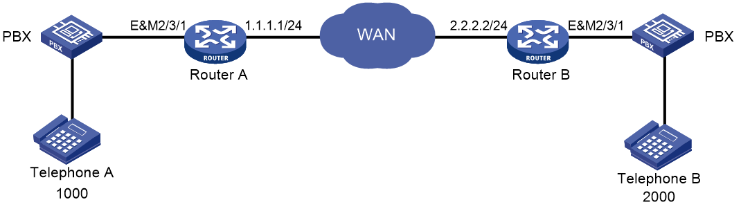
· Busy tone standards—PBX switches might use different busy tone standards. If a user on the PBX side hangs up, the router knows the on-hook operation by detecting a busy tone. If the router cannot correctly identify the played busy tones, the FXO interface on the router will remain seized or goes on-hook prematurely.
As shown in Figure 1, Telephone A establishes a call to Telephone B, and then Telephone A goes on-hook. The PBX plays busy tones to Router A after detecting the on-hook condition of Telephone A. If Router A cannot detect the played busy tones, the FXO interface on Router A will remain seized. To solve this problem, you can configure busy tone detection for the FXO interface.

Two busy tone standards are available: European and North American. After you specify a standard, the device uses a set of parameters compliant with that standard for busy tone detection. If the actual busy tone data do not completely match the set of parameters, the device can use customized busy tone parameters or automatic busy tone detection to accurately detect busy tones.
· Custom busy tone parameters—You can configure busy tone detection by customizing busy tone parameters or configuring automatic busy tone detection. If the tone that the router receives from the PBX matches the busy tone parameters, the router considers the tone as a busy tone and renders the FXO interface on-hook.
As shown in Figure 1, the procedure for automatic busy tone detection is as follows:
a. Place a call from Telephone A to Telephone B.
b. Hang up Telephone A first.
The PBX plays a busy tone to Router A after detecting the on-hook condition.
c. Execute the busytone-detect auto command on Router A to detect busy tones.
As a best practice to ensure that the FXO interface can capture the busy tones sent by the PBX, execute this command two seconds after Telephone A goes on-hook.
The console prompts that busy tone detection is in progress and prompts detection success when the detection is complete.
d. Check whether the detected busy tone parameters are valid by repeating steps 1 and 2.
After Telephone A goes on-hook, the PBX plays a busy tone to Router A. If Router A detects the busy tone, it shuts down the FXO interface.
· Busy tone sending—If the PBX does not play busy tones, configure the FXO interface to send busy tones.
· Silence detection-based automatic on-hook—If the device fails to detect busy tones or the PBX does not play busy tones, you can configure this feature to implement automatic on-hook.
When the duration of silence (whose volume is smaller than the configured threshold) exceeds the configured silence duration, the FXO interface automatically disconnects the call.
|
|
CAUTION: Improper configuration of this feature can lead to false on-hook. To avoid false on-hook, configure multiple sets of parameters and select the set of parameters that will quickly release the FXO interface. |
· Forced on-hook—In some countries, PBXs do not play busy tones, or the busy tones only last for a short period of time. When noise is present on a link, even the silence detection-based automatic on-hook feature (configured with silence-detect threshold) cannot detect the busy tones and fails to release a call after on-hook. To solve this problem, configure the forced on-hook feature.
|
|
NOTE: Forced on-hook disconnects a call when the specified time expires, even if the call is ongoing. |
Configuring a busy tone standard
1. Enter system view.
system-view
2. Enter voice view.
voice-setup
3. Specify a busy tone standard for all FXO interfaces.
area { europe | north-america }
By default, the European standard is used.
Customizing busy tone parameters
1. Enter system view.
system-view
2. Enter voice view.
voice-setup
3. Configure custom busy tone parameters for all FXO interfaces.
busytone-detect custom area-number index argu f1 f2 p1 p2 p3 p4 p5 p6 p7
4. Enable all FXO interfaces to use custom busy tone parameters.
area custom
By default, the European standard is used.
The customized busy tone parameters take effect only after you configure this command.
Configuring automatic busy tone detection
1. Enter system view.
system-view
2. Enter voice view.
voice-setup
3. Configure automatic busy tone detection for an FXO interface.
busytone-detect auto index line-number
4. Return to system view.
quit
5. Enter FXO interface view.
subscriber-line line-number
6. Set the number of busy tone detection periods.
busytone-detect period value
The default is 2.
Test multiple values to select the value that can ensure normal on-hook.
Configuring busy tone sending
1. Enter system view.
system-view
2. Enter FXO interface view.
subscriber-line line-number
3. Enable busy tone sending.
send-busytone enable
By default, this feature is disabled.
4. Set the busy tone duration.
send-busytone time seconds
The default is 3 seconds.
Configuring silence detection-based automatic on-hook
1. Enter system view.
system-view
2. Enter FXO interface view.
subscriber-line line-number
3. Configure silence detection-based automatic on-hook.
silence-detect threshold threshold time time-length
By default, the silence threshold is 20, and the silence duration is 7200 seconds (2 hours).
Configuring forced on-hook
1. Enter system view.
system-view
2. Enter FXO interface view.
subscriber-line line-number
3. Configure forced on-hook.
hookoff-time time
By default, forced on-hook is disabled.
If you configure this command on an FXO interface of a card, the configuration takes effect on all FXO subscriber lines of the card.
Configuring an on-hook delay
About this task
An FXO interface goes on-hook when detecting a busy tone. This will cause the user of an IP phone connected to the FXO interface to mistake the on-hook as a line problem because the user cannot hear the busy tones.
To solve this problem, you can configure a delay time. During the delay time, the FXO interface continues sending the busy tones to the IP phone.
Procedure
1. Enter system view.
system-view
2. Enter FXO interface view.
subscriber-line line-number
3. Set the delay time from when the FXO interface detects a busy tone to when the interface goes on-hook.
busytone-hookon delay-timer value
By default, the delay time is 0 seconds (the FXO interface goes on-hook immediately after detecting a busy tone).
Configuring the off-hook mode
About this task
The FXO interface supports the following off-hook modes:
· Immediate mode—Upon receiving a call, the FXO interface goes off-hook and sends a dial tone to the calling party. Then, the calling party dials the destination number.
· Delay mode—Upon receiving a call, the FXO interface places a call to the specified private line number. When the called party picks up the phone, the FXO goes off-hook. This mode needs to work with the private line auto ring-down (PLAR) feature. For more information about PLAR, see "Configuring dial programs."
Procedure
1. Enter system view.
system-view
2. Enter FXO interface view.
subscriber-line line-number
3. Configure the off-hook mode.
hookoff-mode { delay | immediate }
By default, the immediate mode is used.
Configuring ring detection parameters
About this task
PBXs from different vendors use different types of ring signals. By setting ring detection parameters, you can enable the FXO interface to detect ring signals of different frequencies and waveforms.
Restrictions and guidelines
Do not set the debounce time during a conversation.
Procedure
1. Enter system view.
system-view
2. Enter FXO interface view.
subscriber-line line-number
3. Set the debounce time for ring detection on the FXO interface.
ring-detect debounce value
The default is 10 milliseconds.
As a best practice to prevent line interference from causing false ring tone recognition, set the debounce time to be no less than 8 milliseconds.
If you configure this command on an FXO interface of a card, the configuration takes effect on all FXO subscriber lines of the card.
This command is supported only on the following interface modules:
¡ HMIM-4FXO.
¡ SIC-1FXO.
¡ SIC-2FXO.
4. Set the frequency value for ring detection.
ring-detect frequency value
The default is 40 Hz.
This command is supported only on the following interface modules:
¡ DSIC-4FXS1FXO.
¡ HMIM-8FXS8FXO.
¡ SIC-2FXS1FXO.
Setting the electrical impedance
About this task
The electrical impedance setting must be subject to country specifications. Each country corresponds to an impedance value. You specify an impedance value while specifying a country.
Procedure
1. Enter system view.
system-view
2. Enter FXO interface view.
subscriber-line line-number
3. Set the electrical impedance of a country.
impedance { country-name | r550 | r600 | r650 | r700 | r750 | r800 | r850 | r900 | r950 }
By default, the electrical impedance of China is used.
You must configure the same electrical impedance value on the originating and terminating devices.
Configuring the packet loss compensation mode
About this task
You can configure the packet loss compensation mode to alleviate the impact on voice quality.
· For discrete packet loss, you can use the general compensation mode to reconstruct lost packets.
· For continuous packet loss, you can use the voice gateway-specific compensation mode to reconstruct lost packets.
Procedure
1. Enter system view.
system-view
2. Enter FXO interface view.
subscriber-line line-number
3. Specify a packet loss compensation mode for the FXO interface.
plc-mode { general | specific }
By default, the voice gateway-specific compensation mode is used for an FXO interface.
Enabling online monitoring
Restrictions and guidelines
This feature monitors the physical states of all FXO interfaces on the device.
If this feature is disabled, the device does not detect the physical states of FXO interfaces. All FXO interfaces are always shown in up state.
Procedure
1. Enter system view.
system-view
2. Enter voice view.
voice-setup
3. Enable online monitoring.
monitor enable
By default, online monitoring is enabled.
Binding an FXS interface to an FXO interface
About this task
The one-to-one binding between FXS and FXO interfaces enhances the reliability of voice communication. By working with the PLAR feature, this feature enables the telephone connected to the FXS interface to exclusively use the bound FXO interface to place and receive calls.
The on-hook/off-hook state of the bound FXS and FXO interfaces is consistent. If the FXS interface receives a call when the bound FXS interface goes off-hook, the calling party will hear a busy tone.
Procedure
1. Enter system view.
system-view
2. Enter FXO interface view.
subscriber-line line-number
3. Bind an FXS interface to the FXO interface.
hookoff-mode delay bind fxs-subscriber [ ring-immediately ]
By default, no FXS interface is bound to an FXO interface.
4. Enable the PLAR feature.
private-line string
By default, the PLAR feature is disabled.
For more information about this command, see Voice Command Reference.
5. Set the interval between on-hook and off-hook.
timer hookoff-interval milliseconds
The default is 500 milliseconds.
Configuring an E&M interface
Configuring the cable type
Restrictions and guidelines
You must configure the same cable type for the E&M interfaces on the originating and terminating devices. Otherwise, only one-way voice communication can be implemented.
Procedure
1. Enter system view.
system-view
2. Enter E&M interface view.
subscriber-line line-number
3. Configure the cable type for the E&M interface.
cable { 2-wire | 4-wire }
The default is 4-wire.
Configuring the signal type
1. Enter system view.
system-view
2. Enter E&M interface view.
subscriber-line line-number
3. Configure a signal type for the E&M interface.
type { 1 | 2 | 3 | 5 }
The default is 5 (corresponding to V type signal).
You must configure the same signal type on the originating and terminating devices.
Configuring a start mode for E&M signaling
About this task
E&M signaling supports the following start modes:
· Immediate start—After off-hook, the originating side waits for a specified period of time to send the called number to the terminating side. During this period of time, the originating side does not check whether the terminating side is ready to receive the called number. The terminating side enters off-hook state after receiving the called number.
Figure 2 Immediate start

· Delay start—The originating side goes off-hook and seizes the trunk. After detecting the seizure signal from the originating side, the terminating side enters the off-hook state and remains in this state until it is ready to receive the called number. Then, the terminating side enters the on-hook state and sends a signal to indicate that the line is idle. After receiving the idle signal, the originating side sends the called number to the terminating side, which relays the call to the user phone.
Figure 3 Delay start

· Wink start—The terminating side remains in on-hook state until it receives the seizure signal from the originating side and then sends a wink to the originating side. After receiving the wink, the originating side sends the called number to the terminating side, which relays the call to the user phone.
Figure 4 Wink start

Restrictions and guidelines
You must configure the same start mode for E&M signaling on both the originating and terminating devices.
Configuring the immediate start mode
1. Enter system view.
system-view
2. Enter E&M interface view.
subscriber-line line-number
3. Configure the immediate start mode for the E&M interface.
signal immediate
The default is the immediate start mode.
4. Set a delay for the originating side to wait to send DTMF tones in immediate start mode.
delay send-dtmf milliseconds
The default is 300 milliseconds.
Use this command on the originating device.
Configuring the delay start mode
1. Enter system view.
system-view
2. Enter voice interface view.
subscriber-line line-number
3. Specify the delay start mode for the E&M interface.
signal delay
The default is the immediate start mode.
4. Set the seizure signal duration in delay start mode.
delay hold milliseconds
The default is 400 milliseconds.
Use this command on the terminating device.
5. Set the delay time from when the terminating side detects a seizure signal to when it sends the seizure signal in delay start mode.
delay rising milliseconds
The default is 300 milliseconds.
Use this command on the terminating device.
Configuring the wink start mode
1. Enter system view.
system-view
2. Enter voice interface view.
subscriber-line line-number
3. Specify the wink start mode for the E&M interface.
signal wink
The default is the immediate start mode.
4. Set the delay time from when the terminating side receives a seizure signal to when it sends a wink signal in the wink start mode.
delay send-wink milliseconds
The default is 200 milliseconds.
Use this command on the terminating device.
5. Set the duration of a wink signal sent by the terminating side in wink start mode.
delay wink-hold milliseconds
The default is 500 milliseconds.
Use this command on the terminating device.
6. Set the timeout time for the originating side to wait for a wink signal after sending a seizure signal in the wink start mode.
delay wink-rising milliseconds
The default is 2000 milliseconds.
Use this command on the originating device.
Configuring the E&M non-signaling mode
About this task
The E&M non-signaling mode is applied when the E&M interface of the peer device does not provide the M line and E line. In this mode, the E&M interface communicates with the peer device without signaling. You can configure the PLAR feature by using the private-line command to form a three-segment E&M virtual private line (E&M-VoIP-E&M). When a subscriber picks up the phone, the originating device directly dials the number specified by using the private-line command.
Procedure
1. Enter system view.
system-view
2. Enter voice interface view.
subscriber-line line-number
3. Specify the immediate start mode for the E&M interface.
signal immediate
The default is the immediate start mode.
4. Configure the E&M non-signaling mode.
open-trunk { caller [ monitor interval ] | called }
By default, E&M non-signaling mode is disabled.
Configure the open-trunk caller [ monitor interval ] command on the originating device.
Configure the open-trunk called command on the terminating device.
5. Enable the PLAR feature.
private-line string
Use this command on the originating device.
For more information about the PLAR feature, see "Configuring dial programs."
Enabling E&M control signals pass-through
About this task
This feature operates only when the E&M non-signaling mode is enabled. As shown in Figure 5, an E&M virtual private line is established between the tone generator and the radio. Enable E&M control signals pass-through for Router A and Router B so that they can send seize and idle signals for the E&M virtual line over the IP network.
Figure 5 E&M analog control signals pass-through

Procedure
1. Enter system view.
system-view
2. Enter voice interface view.
subscriber-line line-number
3. Enable E&M control signals pass-through.
passthrough
By default, this feature is disabled.
Configure this command on both the originating and terminating devices.
Configuring the output gain of SLIC chip
About this task
Perform this task to control signal amplification.
Procedure
1. Enter system view.
system-view
2. Enter voice interface view.
subscriber-line line-number
3. Set the output gain of the SLIC chip.
slic-gain { 0 | 1 }
The default is 0 (0.8 dB).
Enabling E&M call logging
About this task
E&M call logging enables the device to log call events on E&M interfaces and send the log messages to the information center. With the information center, you can set log message filtering and output rules, including output destinations. For more information about using the information center, see Network Management and Monitoring Configuration Guide.
Procedure
1. Enter system view.
system-view
2. Enter voice view.
voice-setup
3. Enable E&M call logging.
em log enable
By default, E&M call logging is disabled.
Configuring DTMF signaling
About DTMF signaling
Dual tone multifrequency signaling (DTMF signaling) uses a mixture of a high frequency tone and a lower frequency tone to represent a key on a keypad. Each column of keys is represented by a high frequency tone and each row of keys is represented by a low frequency tone. For example, as shown in Figure 6, the digit 1 is represented by the combination of a pure 697 Hz signal and a pure 1209 Hz signal. These DTMF tones offer good immunity to interference.
Figure 6 DTMF keypad frequencies

A DTMF tone must last a minimum of 45 milliseconds. A minimum interval of 23 milliseconds is required between two DTMF tones to make sure DTMF tones are recognizable. Such requirements are roughly the same in all countries. For more information, see the ITU-T Recommendation Q.24.
Configuring DTMF tone sending
1. Enter system view.
system-view
2. Enter voice view.
voice-setup
3. Set the duration of DTMF tones and the interval between DTMF tones.
dtmf time { interval | persist } milliseconds
The default duration and interval are both 120 milliseconds.
4. Set the amplitude of DTMF tones.
dtmf amplitude value
The default is –9.0 dBm.
Configuring DTMF tone detection
About this task
Perform this task to configure the threshold parameters and sensitivity level for DTMF tone detection.
· The threshold parameters are used to determine whether a DTMF tone is valid. The system calculates the spectrum shape of input DTMF signals and matches the spectrum shape with the threshold parameters. A DTMF tone is considered valid if it matches all threshold parameters.
· The sensitivity level is a trade-off between detection sensitivity and reliability. A higher DTMF detection sensitivity reduces the possibility of missing a true DTMF tone but increases the possibility of false detection. A lower DTMF detection sensitivity reduces the possibility of false detection but increases the possibility of missing a true DTMF tone.
Procedure
1. Enter system view.
system-view
2. Enter voice interface view.
subscriber-line line-number
3. Configure the threshold parameters for DTMF tone detection.
dtmf threshold analog index value
By default, indexes 0 to 12 correspond to 1400, 458, -9, -9, -9, -9, -3, -12, -12, 30, 300, 3200, and 375, respectively.
This command is used by professional personnel to adjust the device in the case of DTMF tone detection failure. Typically, the default value is used.
4. Set the DTMF tone detection sensitivity level.
dtmf sensitivity-level { high | low | medium [ frequency-tolerance value ] }
By default, the DTMF tone detection sensitivity is low.
This command applies only to FXS and FXO interfaces.
This command is supported only on the voice interfaces on the following modules:
¡ DSIC-4FXS1FXO.
¡ HMIM-4FXO.
¡ HMIM-8FXS8FXO.
¡ HMIM-16FXS.
¡ SIC-1FXO.
¡ SIC-2FXO
Adjusting parameters for analog voice interfaces
Adjusting gains
Restrictions and guidelines
You can adjust gains to control the amount of volume in the input or output direction. To avoid call failures, adjust gains only if necessary and do it under the guidance of technical engineers.
Procedure
1. Enter system view.
system-view
2. Enter analog voice interface view.
subscriber-line line-number
3. Set the input gain.
receive gain value
The default is 0 dB.
4. Set the output gain.
transmit gain value
The default is 0 dB.
Adjusting timing parameters
1. Enter system view.
system-view
2. Enter analog voice interface view.
subscriber-line line-number
3. Set the interval between off-hook and dialing the first digit.
timer first-dial seconds
The default is 10 seconds.
This command applies only to FXO and FXS interfaces.
4. Set the maximum interval for dialing the next digit.
timer dial-interval interval
The default is 10 seconds.
5. Set the maximum duration for playing ringback tones.
timer ring-back seconds
The default is 60 seconds.
6. Set the dial delay time.
delay start-dial seconds
The default is 1 second.
This command applies only to FXO and FXS interfaces.
7. Set the hookflash time range.
timer hookflash-detect hookflash-range
By default, the hookflash time range is 50 to 180 milliseconds. If an on-hook condition lasts for a period that falls within the hookflash time range, it is considered a hookflash.
This command applies only to FXS interfaces.
8. Set the maximum duration the terminating device waits for the first digit.
timer wait-digit { seconds | infinity }
The default is 5 seconds.
This command applies only to E&M interfaces.
Enabling the comfortable noise feature
About this task
You can enable this feature to generate comfortable background noise to replace the silent gaps during a conversation.
Procedure
1. Enter system view.
system-view
2. Enter analog voice interface view.
subscriber-line line-number
3. Enable the comfortable noise feature.
cng-on
By default, this feature is enabled.
Configuring echo cancellation
About echo cancellation
An echo is the sound of your own voice going back to the phone receiver when you are speaking. The echo cancellation feature can alleviate the echo problem.
The time when an echo occurs and the size of the echo are relatively fixed. As shown in Figure 7, there is a voice signal at time 0, and an echo occurs after about 40 milliseconds (ms). To cancel this echo, perform the following tasks:
· Set the echo cancellation delay (the time between when an interface sends out a signal and when the interface receives an echo) to 33 ms.
· Set the echo cancellation coverage to 16 ms.

Configuring the echo cancellation feature
1. Enter system view.
system-view
2. Enter analog voice interface view.
subscriber-line line-number
3. Enable the echo cancellation feature.
echo-canceler enable
By default, this feature is enabled.
4. Set the echo cancellation delay.
echo-canceler delay milliseconds
The default is 0 milliseconds.
5. Set the echo cancellation coverage.
echo-canceler tail-length milliseconds
The default is 128 milliseconds.
Adjusting echo cancellation parameters
1. Enter system view.
system-view
2. Enter voice view.
voice-setup
3. Adjust echo cancellation parameters.
echo-canceler { convergence-rate value | max-amplitude value | mix-proportion-ratio value | talk-threshold value }
By default:
¡ The convergence rate of comfort noise amplitude is 0.
¡ The maximum amplitude of comfort noise is 256.
¡ The comfort noise mixture proportion control factor is 100.
¡ The two-way judgment threshold is 1.
The following table describes how to adjust echo cancellation parameters for different symptoms.
|
Symptom |
Parameters adjusted |
|
A user hears echoes or loud background noises from the peer when speaking. |
Speed up the convergence of comfortable noise amplitudes. |
|
There are loud environment noises. |
Increase the maximum amplitude of comfortable noises. |
|
A user hears echoes when speaking. |
Enlarge the mixture proportion control factor of comfortable noises. |
|
There are echoes when both parties speak at the same time. |
Enlarge the two-way judgment threshold. |
Enabling the nonlinear feature of echo cancellation
1. Enter system view.
system-view
2. Enter analog voice interface view.
subscriber-line line-number
3. Enable the nonlinear feature of echo cancellation.
nlp-on
By default, this feature is enabled.
This command takes effect only when the echo-canceler enable command is configured.
After echo cancellation is enabled, nonlinear parts in the line can cause residual echo. The nonlinear feature (also called residual echo suppression) can remove the residual echo.
The following modules do not support this command:
¡ DSIC-4FXS1FXO.
¡ HMIM-8FXS8FXO.
¡ HMIM-16FXS.
Enabling PCM pass-through
Hardware and feature compatibility
|
Hardware |
Feature compatibility |
|
MSR810, MSR810-W, MSR810-W-DB, MSR810-LM, MSR810-W-LM, MSR810-10-PoE, MSR810-LM-HK, MSR810-W-LM-HK, MSR810-LM-CNDE-SJK, MSR810-CNDE-SJK |
No |
|
MSR810-LMS, MSR810-LUS |
No |
|
MSR810-LMS-EA, MSR810-LME |
No |
|
MSR1004S-5G |
No |
|
MSR2600-6-X1, MSR2600-10-X1, MSR2600-15-X1 |
No |
|
MSR 2630 |
No |
|
MSR3600-28, MSR3600-51 |
No |
|
MSR3600-28-SI, MSR3600-51-SI |
No |
|
MSR3600-28-X1, MSR3600-28-X1-DP, MSR3600-51-X1, MSR3600-51-X1-DP |
No |
|
MSR3610-I-DP, MSR3610-IE-DP, MSR3610-IE-ES, MSR3610-IE-EAD, MSR-EAD-AK770, MSR3610-I-IG, MSR3610-IE-IG |
No |
|
MSR3610-X1, MSR3610-X1-DP, MSR3610-X1-DC, MSR3610-X1-DP-DC, MSR3620-X1, MSR3640-X1 |
No |
|
MSR 3610, MSR 3620, MSR 3620-DP, MSR 3640, MSR 3660 |
Yes only on E&M interface modules that use the G.711 A-law codec |
|
MSR3610-G, MSR3620-G |
No |
|
MSR3640-X1-HI |
No |
|
Hardware |
Feature compatibility |
|
MSR810-W-WiNet, MSR810-LM-WiNet |
No |
|
MSR830-4LM-WiNet |
No |
|
MSR830-5BEI-WiNet, MSR830-6EI-WiNet, MSR830-10BEI-WiNet |
No |
|
MSR830-6BHI-WiNet, MSR830-10BHI-WiNet |
No |
|
MSR2600-6-WiNet, MSR2600-10-X1-WiNet |
No |
|
MSR2630-WiNet |
No |
|
MSR3600-28-WiNet |
No |
|
MSR3610-X1-WiNet |
No |
|
MSR3610-WiNet, MSR3620-10-WiNet, MSR3620-DP-WiNet, MSR3620-WiNet, MSR3660-WiNet |
Yes only on E&M interface modules that use the G.711 A-law codec |
|
Hardware |
Feature compatibility |
|
MSR2630-XS |
No |
|
MSR3600-28-XS |
No |
|
MSR3610-XS |
No |
|
MSR3620-XS |
Yes only on E&M interface modules that use the G.711 A-law codec |
|
MSR3610-I-XS |
No |
|
MSR3610-IE-XS |
No |
|
MSR3620-X1-XS |
No |
|
MSR3640-XS |
No |
|
MSR3660-XS |
No |
|
Hardware |
Feature compatibility |
|
MSR810-LM-GL |
No |
|
MSR810-W-LM-GL |
No |
|
MSR830-6EI-GL |
No |
|
MSR830-10EI-GL |
No |
|
MSR830-6HI-GL |
No |
|
MSR830-10HI-GL |
No |
|
MSR1004S-5G-GL |
No |
|
MSR2600-6-X1-GL |
No |
|
MSR3600-28-SI-GL |
No |
Restrictions and guidelines
This feature is supported only when G.711 A-Law is used. For this feature to take effect on a subcard, you must reboot the subcard.
Procedure
1. Enter system view.
system-view
2. Enter voice view.
voice-setup
3. Enable PCM pass-through.
In standalone mode:
pcm-passthrough subslot subslot-number
In IRF mode:
pcm-passthrough slot slot-number subslot subslot-number
By default, PCM pass-through is disabled.
4. Identify whether PCM pass-through takes effect.
display device verbose
Display and maintenance commands for analog voice interfaces
Execute display commands in any view.
|
Task |
Command |
|
Display information about analog voice interfaces. |
display voice subscriber-line |
Analog voice interface configuration examples
Example: Configuring two-dial for FXO interfaces
Network configuration
As shown in Figure 8, Router A and Router B are connected through an IP network and can reach each other. The PBX is configured with a trunk number 07552003.
Configure the two routers to enable Telephone B to establish a call with Telephone A through two dials.

Procedure
1. On Router A, configure the local number as 0101001 for POTS entity 1001, and bind FXS interface line 2/1/1 to the POTS entity.
<RouterA> system-view
[RouterA] voice-setup
[RouterA-voice] dial-program
[RouterA-voice-dial] entity 1001 pots
[RouterA-voice-dial-entity1001] match-template 0101001
[RouterA-voice-dial-entity1001] line 2/1/1
2. Configure Router B:
# Configure the called number as 0101001 for VoIP entity 010, and configure the destination IP address as 1.1.1.1.
<RouterB> system-view
[RouterB] voice-setup
[RouterB-voice] dial-program
[RouterB-voice-dial] entity 010 voip
[RouterB-voice-dial-entity10] match-template 0101001
[RouterB-voice-dial-entity10] address sip ip 1.1.1.1
[RouterB-voice-dial-entity10] quit
# Configure the local number as 07552001 for POTS entity 2001, and bind FXO interface line 2/1/1 to POTS entity 2001.
[RouterB-voice-dial] entity 2001 pots
[RouterB-voice-dial-entity2001] match-template 07552001
[RouterB-voice-dial-entity2001] line 2/1/1
# Configure the number sending mode as all.
[RouterB-voice-dial-entity2001] send-number all
Verifying the configuration
# Dial 07552003 from Telephone B.
# After hearing a dial tone, dial 0101001 (Telephone A) from Telephone B to verify that Telephone B can establish calls with Telephone A through two dials.
Example: Configuring PLAR for FXO interfaces
Network configuration
As shown in Figure 9, Router A and Router B are connected through an IP network and can reach each other. The PBX is configured with a trunk number 07552003.
Configure PLAR for the FXO interface of Router B. When the user of Telephone B dials 07552003, the FXO interface automatically calls Telephone A.

Procedure
1. On Router A, configure the local number as 0101001 for POTS entity 1001, and bind FXS interface line 2/1/1 to the POTS entity.
<RouterA> system-view
[RouterA] voice-setup
[RouterA-voice] dial-program
[RouterA-voice-dial] entity 1001 pots
[RouterA-voice-dial-entity1001] match-template 0101001
[RouterA-voice-dial-entity1001] line 2/1/1
2. Configure Router B:
# Configure the called number as 0101001 for VoIP entity 010, and configure the destination IP address as 1.1.1.1.
<RouterB> system-view
[RouterB] voice-setup
[RouterB-voice] dial-program
[RouterB-voice-dial] entity 010 voip
[RouterB-voice-dial-entity10] match-template 0101001
[RouterB-voice-dial-entity10] address sip ip 1.1.1.1
[RouterB-voice-dial-entity10] quit
# Configure the local number as 07552001 for POTS entity 2001, and bind FXO interface line 2/1/1 to the POTS entity.
[RouterB-voice-dial] entity 2001 pots
[RouterB-voice-dial-entity2001] match-template 07552001
[RouterB-voice-dial-entity2001] line 2/1/1
# Configure the number sending mode as all.
[RouterB-voice-dial-entity2001] send-number all
# Enable the PLAR feature and configure the delay off-hook mode for the FXO interface.
[RouterB] subscriber-line 2/1/1
[RouterB-subscriber-line2/1/1] private-line 0101001
[RouterB-subscriber-line2/1/1] hookoff-mode delay
Verifying the configuration
# Dial 07552003 from Telephone B to verify that Telephone B can automatically establish calls with Telephone A through the PLAR feature.
Example: Configuring E&M interfaces
Network configuration
As shown in Figure 10, Router A and Router B are connected through an IP network and can reach each other.
Configure the two routers to enable Telephone A and Telephone B to establish calls.

Procedure
1. Configure Router A:
# Configure the called number as 07552001 for VoIP entity 0755, and configure the destination IP address as 2.2.2.2.
<RouterA> system-view
[RouterA] voice-setup
[RouterA-voice] dial-program
[RouterA-voice-dial] entity 0755 voip
[RouterA-voice-dial-entity755] match-template 07552001
[RouterA-voice-dial-entity755] address sip ip 2.2.2.2
[RouterA-voice-dial-entity755] quit
# Configure the local number as 0101001 for POTS entity 1001, and bind FXS interface line 2/1/1 to the POTS entity.
[RouterA-voice-dial] entity 1001 pots
[RouterA-voice-dial-entity1001] match-template 0101001
[RouterA-voice-dial-entity1001] line 2/1/1
2. Configure Router B:
# Configure the called number as 0101001 for VoIP entity 010, and configure the destination IP address as 1.1.1.1.
<RouterB> system-view
[RouterB] voice-setup
[RouterB-voice] dial-program
[RouterB-voice-dial] entity 010 voip
[RouterB-voice-dial-entity10] match-template 0101001
[RouterB-voice-dial-entity10] address sip ip 1.1.1.1
[RouterB-voice-dial-entity10] quit
# Configure the local number as 07552001 for POTS entity 2001, and bind E&M interface line 2/3/1 to the POTS entity.
[RouterB-voice-dial] entity 2001 pots
[RouterB-voice-dial-entity2001] match-template 07552001
[RouterB-voice-dial-entity2001] send-number all
[RouterB-voice-dial-entity2001] line 2/3/1
[RouterB-voice-dial-entity2001] return
# Enter the view of E&M interface 5/0. The E&M interface must have the same configuration as the connected PBX.
<RouterB> system-view
[RouterB] subscriber-line 2/3/1
# Configure the wink start mode.
[RouterB-subscriber-line2/3/1] signal wink
# Configure the 4-wire cable type (optional, because the default is the 4-wire cable type).
[RouterB-subscriber-line2/3/1] cable 4-wire
# Configure the signal type as 5 (optional, because the default is 5).
[RouterB-subscriber-line2/3/1] type 5
Verifying the configuration
# Dial 07552001 (Telephone B) from Telephone A to verify that Telephone A can establish calls with Telephone B.
# Dial 0101001 (Telephone A) from Telephone B to verify that Telephone B can establish calls with Telephone A.
Example: Configuring E&M non-signaling mode
Network configuration
As shown in Figure 11, configure the PLAR mode for the E&M interface on Router A. When the user of Telephone A picks up the handset, the E&M interface automatically calls Telephone B.
Procedure
1. Configure Router A:
# Configure the called number as 2000 for VoIP entity 2000, and configure the destination IP address as 2.2.2.2.
<RouterA> system-view
[RouterA] voice-setup
[RouterA-voice] dial-program
[RouterA-voice-dial] entity 2000 voip
[RouterA-voice-dial-entity2000] match-template 2000
[RouterA-voice-dial-entity2000] address sip ip 2.2.2.2
[RouterA-voice-dial-entity2000] quit
# Configure the local number as 1000 for POTS entity 1000, and bind E&M interface line 2/3/1 to the POTS entity.
[RouterA-voice-dial] entity 1000 pots
[RouterA-voice-dial-entity1000] match-template 1000
[RouterA-voice-dial-entity1000] line 2/3/1
[RouterA-voice-dial-entity1000] return
# Enter the view of the E&M interface line 2/3/1.
<RouterA> system-view
[RouterA] subscriber-line 2/3/1
# Configure the immediate start mode (optional, because the default is the immediate start mode).
[RouterA-subscriber-line2/3/1] signal immediate
# Enable the PLAR feature.
[RouterA-subscriber-line2/3/1] private-line 2000
# Enable the E&M non-signaling mode.
[RouterA-subscriber-line2/3/1] open-trunk caller
# Enable E&M control signals pass-through.
[RouterA-subscriber-line2/3/1] passthrough
# Disable the echo cancellation feature.
[RouterA-subscriber-line2/3/1] undo echo-canceler enable
2. Configure Router B:
# Configure the called number as 1000 for VoIP entity 1000, and configure the destination IP address as 1.1.1.1.
<RouterB> system-view
[RouterB] voice-setup
[RouterB-voice] dial-program
[RouterB-voice-dial] entity 1000 voip
[RouterB-voice-dial-entity1000] match-template 1000
[RouterB-voice-dial-entity1000] address sip ip 1.1.1.1
[RouterB-voice-dial-entity1000] quit
# Configure the local number as 2000 for POTS entity 2000, and bind E&M interface line 2/3/1 to the POTS entity.
[RouterB-voice-dial] entity 2000 pots
[RouterB-voice-dial-entity2000] match-template 2000
[RouterB-voice-dial-entity2000] line 2/3/1
[RouterB-voice-dial-entity2000] return
# Enter the view of the E&M interface line 2/3/1.
<RouterB> system-view
[RouterB] subscriber-line 2/3/1
# Configure the immediate start mode. The default is the immediate start mode.
[RouterB-subscriber-line2/3/1] signal immediate
# Enable the E&M non-signaling mode.
[RouterB-subscriber-line2/3/1] open-trunk called
# Enable E&M control signals pass-through.
[RouterB-subscriber-line2/3/1] passthrough
# Disable the echo cancellation feature.
[RouterB-subscriber-line2/3/1] undo echo-canceler enable
Verifying the configuration
# Pick up the handset of Telephone A to verify that Telephone A can automatically establish calls with Telephone B through the PLAR feature.
Example: Configuring FXS&FXO 1:1 bindings
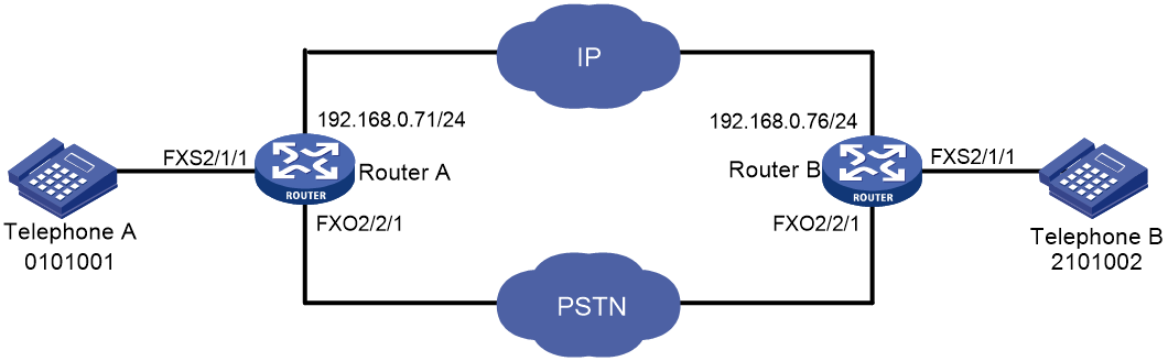
Network configuration
As shown in Figure 12, Telephone A calls Telephone B through the IP network. When the IP network is unavailable, Telephone A uses the bound FXO interface to call Telephone B through the PSTN network.
Procedure
1. Configure Router A:
# Configure the called number template as 210…. for VoIP entity 210, and configure the destination IP address as 192.168.0.76.
<RouterA> system-view
[RouterA] voice-setup
[RouterA-voice] dial-program
[RouterA-voice-dial] entity 210 voip
[RouterA-voice-dial-entity210] match-template 210....
[RouterA-voice-dial-entity210] address sip ip 192.168.0.76
[RouterA-voice-dial-entity210] quit
# Configure the local number as 0101001 for POTS entity 0101001, and bind the FXS interface line 2/1/1 to the POTS entity.
[RouterA-voice-dial] entity 0101001 pots
[RouterA-voice-dial-entity101001] match-template 0101001
[RouterA-voice-dial-entity101001] line 2/1/1
[RouterA-voice-dial-entity101001] quit
# Configure the called number template as .T for POTS entity 211 used for call backup on FXO interface line 2/2/1, and configure the permitted calling number as 0101001.
[RouterA-voice-dial] entity 211 pots
[RouterA-voice-dial-entity211] match-template .T
[RouterA-voice-dial-entity211] line 2/2/1
[RouterA-voice-dial-entity211] send-number all
[RouterA-voice-dial-entity211] caller-permit 0101001
[RouterA-voice-dial-entity211] quit
[RouterA-voice-dial] quit
[RouterA-voice] quit
# Enable the PLAR feature for the FXO interface line 2/2/1, and bind the FXS interface line 2/1/1 to the FXO interface line 2/2/1.
[RouterA] subscriber-line 2/2/1
[RouterA-subscriber-line2/2/1] private-line 0101001
[RouterA-subscriber-line2/2/1] hookoff-mode delay bind 2/1/1
2. Configure Router B:
# Configure the called number template as 010…. for VoIP entity 010, and configure the destination IP address as 192.168.0.71.
<RouterB> system-view
[RouterB] voice-setup
[RouterB-voice] dial-program
[RouterB-voice-dial] entity 010 voip
[RouterB-voice-dial-entity10] match-template 010....
[RouterB-voice-dial-entity10] address sip ip 192.168.0.71
[RouterB-voice-dial-entity10] quit
# Configure the local number as 2101002 for POTS entity 2101002, and bind the FXS interface line 2/1/1 to the POTS entity.
[RouterB-voice-dial] entity 2101002 pots
[RouterB-voice-dial-entity2101002] match-template 2101002
[RouterB-voice-dial-entity2101002] line 2/1/1
[RouterB-voice-dial-entity2101002] quit
# Configure the called number template as .T for POTS entity 011 used for call backup on FXO interface line 2/2/1, and configure the permitted calling number as 2101002.
[RouterB-voice-dial] entity 011 pots
[RouterB-voice-dial-entity11] match-template .T
[RouterB-voice-dial-entity11] line 2/2/1
[RouterB-voice-dial-entity11] send-number all
[RouterB-voice-dial-entity11] caller-permit 2101002
[RouterB-voice-dial-entity11] quit
[RouterB-voice-dial] quit
[RouterB-voice] quit
# Enable the PLAR feature for the FXO interface line 2/2/1, and bind the FXS interface line 2/1/1 to the FXO interface line 2/2/1.
[RouterB] subscriber-line 2/2/1
[RouterB-subscriber-line2/2/1] private-line 2101002
[RouterB-subscriber-line2/2/1] hookoff-mode delay bind 1/0
Verifying the configuration
# When the IP network is available, place a call to verify that the call is established through the IP network.
# When the IP network is unavailable, place a call to verify that the call is established through the PSTN.
Configuring digital voice interfaces
About digital voice interfaces
Digital voice interfaces include E1, T1, and BSV interfaces.
E1 and T1 interfaces
E1 interfaces (also called VE1 interfaces) and T1 interfaces (also called VT1 interfaces) can connect to the PSTN as trunk interfaces. An E1 interface provides 32 timeslots and 2.048 Mbps bandwidth. A T1 interface provides 24 timeslots and 1.544 Mbps bandwidth. ITU-T E1 is used mainly in Europe and China. ANSI T1 is used mainly in America, Canada, and Japan.
E1/T1 voice transmission allows a router to provide more communication channels, which improves router utilization.
Figure 13 shows a typical network for E1/T1 interfaces.

BSV interfaces
BRI S/T voice (BSV) interfaces can compress, send, receive, and decompress voice packets. BSV interfaces connect to PBXs as trunk interfaces. A BSV interface provides two B channels and one D channel (2B+D) and supports only DSS1 signaling.
Restrictions: Hardware compatibility with digital voice interfaces
|
Hardware |
Digital voice interface compatibility |
|
MSR810, MSR810-W, MSR810-W-DB, MSR810-LM, MSR810-W-LM, MSR810-10-PoE, MSR810-LM-HK, MSR810-W-LM-HK, MSR810-LM-CNDE-SJK, MSR810-CNDE-SJK |
No |
|
MSR810-LMS, MSR810-LUS |
No |
|
MSR810-LMS-EA, MSR810-LME |
No |
|
MSR1004S-5G |
No |
|
MSR2600-6-X1, MSR2600-15-X1 |
No |
|
MSR2600-10-X1 |
Yes |
|
MSR 2630 |
Yes |
|
MSR3600-28, MSR3600-51 |
Yes |
|
MSR3600-28-SI, MSR3600-51-SI |
No |
|
MSR3600-28-X1, MSR3600-28-X1-DP, MSR3600-51-X1, MSR3600-51-X1-DP |
No |
|
MSR3610-I-DP, MSR3610-IE-DP, MSR3610-IE-ES, MSR3610-IE-EAD, MSR-EAD-AK770, MSR3610-I-IG, MSR3610-IE-IG |
No |
|
MSR3610-X1, MSR3610-X1-DP, MSR3610-X1-DC, MSR3610-X1-DP-DC, MSR3620-X1, MSR3640-X1 |
No |
|
MSR 3610, MSR 3620, MSR 3620-DP, MSR 3640, MSR 3660 |
No |
|
MSR3610-G, MSR3620-G |
Yes |
|
MSR3640-X1-HI |
No |
|
Hardware |
Digital voice interface compatibility |
|
MSR810-W-WiNet, MSR810-LM-WiNet |
No |
|
MSR830-4LM-WiNet |
No |
|
MSR830-5BEI-WiNet, MSR830-6EI-WiNet, MSR830-10BEI-WiNet |
No |
|
MSR830-6BHI-WiNet, MSR830-10BHI-WiNet |
No |
|
MSR2600-6-WiNet |
No |
|
MSR2600-10-X1-WiNet |
Yes |
|
MSR2630-WiNet |
Yes |
|
MSR3600-28-WiNet |
Yes |
|
MSR3610-X1-WiNet |
No |
|
MSR3610-WiNet, MSR3620-10-WiNet, MSR3620-DP-WiNet, MSR3620-WiNet, MSR3660-WiNet |
Yes |
|
Hardware |
Digital voice interface compatibility |
|
MSR2630-XS |
No |
|
MSR3600-28-XS |
No |
|
MSR3610-XS |
No |
|
MSR3620-XS |
Yes |
|
MSR3610-I-XS |
No |
|
MSR3610-IE-XS |
No |
|
MSR3620-X1-XS |
No |
|
MSR3640-XS |
No |
|
MSR3660-XS |
No |
|
Hardware |
Digital voice interface compatibility |
|
MSR810-LM-GL |
No |
|
MSR810-W-LM-GL |
No |
|
MSR830-6EI-GL |
No |
|
MSR830-10EI-GL |
No |
|
MSR830-6HI-GL |
No |
|
MSR830-10HI-GL |
No |
|
MSR1004S-5G-GL |
No |
|
MSR2600-6-X1-GL |
No |
|
MSR3600-28-SI-GL |
No |
Digital voice interface tasks at a glance
E1 and T1 interface tasks at a glance
To configure E1 and T1 interfaces, perform the following tasks:
1. (Optional.) Configuring basic settings for digital voice interfaces
2. Configuring basic parameters for an E1 or T1 interface
¡ Configuring basic parameters for an E1 interface
¡ Configuring basic parameters for a T1 interface
b. Configuring a logical digital voice interface
You must configure a timeslot set when you use R2 signaling and configure features for the logical digital voice interface associated with the timeslot set.
4. Configuring signaling
Perform one of the following tasks:
¡ Configuring the ISDN protocol
5. Binding a digital voice interface to a POTS entity
6. (Optional.) Configuring reverse charging
7. (Optional.) Enabling the device to treat DISCONNECT messages with PI 8 as standard DISCONNECT messages
8. (Optional.) Adjusting parameters for digital voice interfaces
BSV interface tasks at a glance
To configure BSV interfaces, perform the following tasks:
1. Configuring a BSV interface
2. Configuring the ISDN protocol
3. Binding a digital voice interface to a POTS entity
4. (Optional.) Configuring reverse charging
5. (Optional.) Enabling the device to treat DISCONNECT messages with PI 8 as standard DISCONNECT messages
6. (Optional.) Adjusting parameters for digital voice interfaces
Configuring basic settings for digital voice interfaces
Configuring the description for a digital voice interface
1. Enter system view.
system-view
2. Enter digital voice interface view.
subscriber-line line-number:{ ts-set-number | 15 | 23 }
3. Configure the description for the digital voice interface.
description text
By default, the description of a digital voice interface is interface name Interface.
Bring up a digital voice interface
1. Enter system view.
system-view
2. Enter digital voice interface view.
subscriber-line line-number:{ ts-set-number | 15 | 23 }
3. Bring up the digital voice interface.
undo shutdown
By default, a digital voice interface is up.
Restoring the default settings for a digital voice interface
|
|
IMPORTANT: This task might interrupt ongoing network services. Make sure you are fully aware of the impacts of this task before you perform it on a live network. |
Restrictions and guidelines
The default command might fail to restore the default settings for some commands because of reasons such as command dependencies or system restrictions. Use the display this command in interface view to identify these commands. Then use their undo forms or follow the command reference to restore their default settings. If your restoration attempt still fails, follow the error message instructions to resolve the problem.
Procedure
1. Enter system view.
system-view
2. Enter digital voice interface view.
subscriber-line line-number:{ ts-set-number | 15 | 23 }
3. Restore the default settings for the digital voice interface.
default
Configuring basic parameters for an E1 interface
Configuring a TDM clock source
About this task
E1 interfaces must use a common TDM clock source during timeslot interchange to prevent frame slips and bit errors.
When both E1 and T1 interface modules are present on a device, all the E1 or T1 SIC interface modules are a subsystem, and each E1 or T1 HMIM interface module is a subsystem. Each subsystem determines the clock source according to the following rules:
· If the line keyword is specified for all interfaces, the clock on the interface with the lowest number is used. If the interface goes down, the clock on the interface with the second lowest number is used.
· If the line and primary keywords are specified for one interface and the line or internal keyword is specified for all other interfaces, the clock on that one interface is used.
· If the line keyword is specified for one interface and the internal keyword is specified for all other interfaces, the clock on that one interface is used.
· The clock source of only one interface can be set to line primary.
Restrictions and guidelines
The TDM clock sources on the local and peer devices must match. For example, if you set the clock source to line for a subsystem on the local device, you must set the clock source to internal on the peer device, and vice versa.
Procedure
1. Enter system view.
system-view
2. Enter E1 interface view.
controller e1 number
3. Configure a TDM clock source for the E1 interface.
tdm-clock { internal | line [ primary ] }
The default is internal.
Configuring parameters for an E1 interface
1. Enter system view.
system-view
2. Enter E1 interface view.
controller e1 number
3. Configure the description for the E1 interface.
description text
The default is interface name Interface.
4. Configure the framing format for the E1 interface.
frame-format { crc4 | no-crc4 }
The default is no-crc4.
5. Set the line coding format for the E1 interface.
code { ami | hdb3 }
The default is hdb3.
6. Set the cable type for the E1 interface.
cable { long | short }
The default is long.
7. Configure the link idle code type for the E1 interface.
idle-code { 7e | ff }
The default is 0x7E.
8. Set the interframe filling tag type for the E1 interface.
itf type { 7e | ff }
The default is 0x7E.
9. (Optional.) Enable loopback and set the loopback mode for the E1 interface.
loopback { local | payload | remote }
By default, loopback is disabled.
10. Bring up the E1 interface.
undo shutdown
By default, an E1 interface is up.
For more information about the commands in this task, see WAN interface commands in Interface Command Reference.
Restoring the default settings for an E1 interface
|
|
IMPORTANT: This task might interrupt ongoing network services. Make sure you are fully aware of the impacts of this task before you perform it on a live network. |
Restrictions and guidelines
The default command might fail to restore the default settings for some commands because of reasons such as command dependencies or system restrictions. Use the display this command in interface view to identify these commands. Then use their undo forms or follow the command reference to restore their default settings. If your restoration attempt still fails, follow the error message instructions to resolve the problem.
Procedure
1. Enter system view.
system-view
2. Enter E1 interface view.
controller e1 number
3. Restore the default settings for the E1 interface.
default
Configuring basic parameters for a T1 interface
Configuring a TDM clock source
About this task
A T1 interface has the same TDM clock source configuration as an E1 interface. For more information, see "Configuring a TDM clock source."
Procedure
1. Enter system view.
system-view
2. Enter T1 interface view.
controller t1 number
3. Configure a TDM clock source for the T1 interface.
tdm-clock { internal | line [ primary ] }
The default is internal.
Configuring parameters for a T1 interface
1. Enter system view.
system-view
2. Enter T1 interface view.
controller t1 number
3. (Optional.) Configure the description for the T1 interface.
description text
The default is interface name Interface.
4. Configure the framing format for the T1 interface.
frame-format { esf | sf }
The default is esf.
5. Set the line coding format for the T1 interface.
code { ami | b8zs }
The default is b8zs.
6. Set the cable type for the T1 interface.
cable { long | 0db | -7.5db | -15db | -22.5db | short | 133ft | 266ft | 399ft | 533ft | 655ft }
The default is long 0db.
7. Set the interframe filling tag type for the T1 interface.
itf type { 7e | ff }
The default is 0x7E.
8. Set alarm thresholds for the T1 interface.
alarm-threshold { ais { level-1 | level-2 } | lfa { level-1 | level-2 | level-3 | level-4 } | los { pulse-detection | pulse-recovery } value }
By default:
¡ For LOS alarms, the threshold of pulse-detection is 176 and the threshold of pulse-recovery is 22. If the number of pulses detected during the total length of 176 pulse detection intervals is smaller than 22 (the pulse-recovery threshold), a LOS alarm occurs.
¡ Both AIS alarm threshold and LFA alarm threshold are level-1.
9. Enable loopback and set the loopback mode for the T1 interface.
loopback { local | payload | remote }
By default, loopback is disabled.
10. Bring up the T1 interface.
undo shutdown
By default, a T1 interface is up.
For more information about the commands in this task, see WAN interface commands in Interface Command Reference.
Restoring the default settings for a T1 interface
|
|
IMPORTANT: This task might interrupt ongoing network services. Make sure you are fully aware of the impacts of this task before you perform it on a live network. |
Restrictions and guidelines
The default command might fail to restore the default settings for some commands because of reasons such as command dependencies or system restrictions. Use the display this command in interface view to identify these commands. Then use their undo forms or follow the command reference to restore their default settings. If your restoration attempt still fails, follow the error message instructions to resolve the problem.
Procedure
1. Enter system view.
system-view
2. Enter T1 interface view.
controller t1 number
3. Restore the default settings for the T1 interface.
default
Configuring a BSV interface
About BSV interfaces
A BSV interface can generate basic rate interfaces (BRIs) and logical digital voice interfaces.
· BRI—Can be used only for voice transmission.
· Logical digital voice interface—Can be configured with voice commands. A logical digital voice interface has two subinterfaces, which correspond to the two B channels. You cannot configure commands on the subinterfaces, but you can use the display voice subscriber-line line-number.subnumber command to view the call state of a subinterface.
Restrictions and guidelines for BSV interface configuration
For more information about commands in this task, see WAN interface commands in Interface Command Reference.
Configuring basic parameters for a BSV interface
1. Enter system view.
system-view
2. Enter BRI interface view.
interface bri interface-number
3. (Optional.) Configure the description for the BRI interface.
description text
The default is interface name Interface.
4. (Optional.) Enable loopback detection for B channels.
loopback { b1 | b2 | both }
By default, loopback detection is disabled.
5. (Optional.) Set the expected bandwidth of the interface.
bandwidth bandwidth-value
The default is 0 kbps.
6. Set the MTU of the BRI interface.
mtu size
The default is 1500 bytes.
7. Set the polling interval for the BRI interface.
timer-hold seconds
The default is 10 seconds.
8. Bring up the BRI interface.
undo shutdown
By default, a BRI interface is up.
9. (Optional.) Activate the BRI interface.
activate
By default, a BRI interface is not activated.
Restoring the default settings for a BSV interface
|
|
IMPORTANT: This task might interrupt ongoing network services. Make sure you are fully aware of the impacts of this task before you perform it on a live network. |
Restrictions and guidelines
The default command might fail to restore the default settings for some commands because of reasons such as command dependencies or system restrictions. Use the display this command in interface view to identify these commands. Then use their undo forms or follow the command reference to restore their default settings. If your restoration attempt still fails, follow the error message instructions to resolve the problem.
Procedure
1. Enter system view.
system-view
2. Enter BRI interface view.
interface bri interface-number
3. Restore the default settings for the interface.
default
Configuring a timeslot set
Creating a timeslot set
About this task
After you create a timeslot set and configure its signaling type on an E1 interface, the system automatically creates a logical digital voice interface. Timeslot 0 is used for frame synchronization, timeslot 16 is used to transmit signaling, and the other 30 timeslots are used to transmit voice packets.
A T1 interface is used in a similar way to an E1 interface, except that it has 24 timeslots and timeslot 24 is used to transmit signaling.
Procedure
1. Enter system view.
system-view
2. Enter E1 or T1 interface view.
controller { e1 | t1 } number
3. Create a timeslot set and enable R2 signaling for it.
timeslot-set ts-set-number timeslot-list timeslots-list signal r2
Only RS signaling can be configured for a timeslot set.
Configuring a logical digital voice interface
Restrictions and guidelines
The system automatically creates a logical voice interface in the form of E1/T1 interface number:timeslot set number for a timeslot set.
Procedure
1. Enter system view.
system-view
2. Enter E1 or T1 interface view.
controller { e1 | t1 } number
3. Create a timeslot set and enable R2 signaling for it.
timeslot-set ts-set-number timeslot-list timeslots-list signal r2
4. Return to system view.
quit
5. Enter digital voice interface view.
subscriber-line number:ts-set-number
6. Configure a companding law for PCM.
pcm { a-law | μ-law }
The default is a-law for logical digital voice interfaces of E1 interfaces and μ-law for logical digital voice interfaces of T1 interfaces.
Configuring R2 signaling
About R2 signaling
ITU-T recommendations Q.400 through Q.490 define the R2 signaling standards. However, the R2 signaling standards implemented in different countries and regions are ITU variants.
In R2 signaling, the calling side acts as the originating PBX, and the called side acts as the terminating PBX. Signaling sent by the originating PBX is called forward signaling, and signaling sent by the terminating PBX is called backward signaling, as shown in Figure 14.
Figure 14 R2 signaling elements

R2 signaling includes digital line signaling and interregister signaling. Digital line signaling conveys status information about E1 trunks to describe whether the trunks are seized, released, or blocked. Interregister signaling transmits and requests calling and called numbers.
ITU-T digital line signaling
Digital line signaling monitors the state of a trunk and controls calls. It can identify the following state changes:
· The calling party goes off-hook and seizes the line.
· The called party goes off-hook and answers the call.
· The calling party releases the call.
· The called party releases the call.
Digital line signaling sets the line to be idle or seized according to the state of the trunk. This signaling is transmitted through timeslot 16. The two transmission directions of each line have four bits (A, B, C and D) as flag bits, with C and D bits fixed to 01. The forward line signaling adopts af and bf bits, and the backward line signaling adopts ab and bb bits, as shown in Table 1.
Table 1 Line signaling bit description
|
Bit |
Description |
Value = 0 |
Value = 1 |
|
af |
Identifies the state of the originating device and indicates the state of the calling line. |
Off-hook, seized |
On-hook (idle) |
|
bf |
Indicates a fault state from the originating side to the terminating side. |
Normal |
Faulty |
|
ab |
Indicates the state of the called line (on-hook or off-hook). |
Off-hook by called party |
On-hook by called party |
|
bb |
Indicates the state of the terminating device (idle or seized). |
Idle |
Seized or blocked |
Table 2 State code of line signaling
|
State of the circuit |
Signaling code |
|||
|
Forward |
Backward |
|||
|
af |
bf |
ab |
bb |
|
|
Idle or release |
1 |
0 |
1 |
0 |
|
Seized |
0 |
0 |
1 |
0 |
|
Seizure-ack |
0 |
0 |
1 |
1 |
|
Answer |
0 |
0 |
0 |
1 |
|
Clear-back |
0 |
0 |
1 |
1 |
|
Clear-forward |
1 |
0 |
0/1 |
1 |
|
Blocked |
1 |
0 |
1 |
1 |
|
Unblocked |
1 |
0 |
1 |
0 |
R2 digital line signaling exchange includes the following processes:
· Call establishment.
When the circuit is idle, the originating side sends a forward seizure signal (00) to the terminating side, and the terminating side sends back a seizure acknowledgment signal (11). Then the circuit is seized, and interregister signaling exchange begins. When the called party picks up the phone, the terminating side sends a backward answer signal (01). After the originating side recognizes the received signal, it establishes the call.
Figure 15 Call establishment
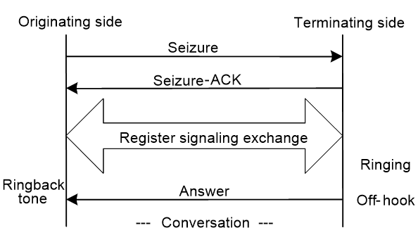
· Call release at the originating side.
The originating side sends a clear-forward signal 10. When the terminating side recognizes the clear-forward signal, it sends a backward signal 10. When the originating side recognizes the backward signal 10, it releases the call.
Figure 16 Call release at originating side

· Call release at the terminating side.
The terminating side sends a clear-back signal 11 to the originating side, and the originating side sends back a clear-forward signal 10. When the terminating side recognizes the forward signal 10, it sends a release-guard signal 10. When the originating side recognizes the release-guard signal 10, it releases the call.
Figure 17 Call release at terminating side

· Blocking in idle state or during conversation.
After the originating side receives a blocking signal 11 from the terminating side when the circuit is idle or during conversation, the circuit is blocked. In this case, the originating side still sends the forward signal 10 to indicate that the line is idle. When the terminating side unblocks the circuit, it sends a backward signal 10 to indicate that the line is idle. The originating side maintains the forward signal 10 and unblocks the local-end circuit for the next call.
ITU-T interregister signaling
Interregister signaling transmits and requests calling and called numbers. It adopts the multifrequency compelled (MFC) mode and includes forward signaling and backward signaling. Forward signaling exchange includes Group I and Group II, and backward signaling exchange includes Group A and Group B. When the originating side recognizes the seizure acknowledgment signal, interregister signaling begins to send the first digit of the called number, and waits for the response of Group A signaling from the terminating side.
· Group I forward signals—Include connection control signals and digit signals.
Table 3 Forward Group I signals
|
Designation |
Definition |
|
I-1 through I-10 |
Digits 1, 2, 3, 4, 5, 6, 7, 8, 9, and 0, responsible for sending number information to the terminating side. |
|
I-11 |
Spare for national use. |
|
I-12 |
Request refused. |
|
I-13 |
Connected to tested device. |
|
I-14 |
Spare for national use. |
|
I-15 |
Address identification terminator and pulse terminator (used in international calls). |
· Group A backward signals—Control signals used for controlling and acknowledging Group I forward signals.
Table 4 Group A backward signals
|
Designation |
Definition |
|
A-1 |
Send next digit. |
|
A-2 |
Send last but one digit. |
|
A-3 |
Address-complete; changeover to reception of Group B signals. |
|
A-4 |
Congestion in the national network. |
|
A-5 |
Send calling party's category. |
|
A-6 |
Address-complete, charge, and set up speech conditions. |
|
A-7 |
Send last but two digits. |
|
A-8 |
Send last but three digits. |
|
A-9 |
Spare for national use. |
|
A-10 |
Spare for national use. |
|
A-11 |
Send country code indicator. |
|
A-12 |
Send language or discrimination digit. |
|
A-13 |
Send nature of circuit. |
|
A-14 |
Request for information on use of an echo canceller (is an incoming half-echo suppressor required?). |
|
A-15 |
Congestion in an international exchange. Terminate interregister signaling interaction. |
· Group II forward signals—Identify the calling party category. The system looks at the calling party category to decide whether the calling party can perform forced release or break-in.
Table 5 Group II forward signals
|
Designation |
Definition |
|
II-1 |
Subscriber without priority. |
|
II-2 |
Subscriber with priority. |
|
II-3 |
Maintenance equipment. |
|
II-4 |
Spare for national use. |
|
II-5 |
Operator. |
|
II-6 |
Data transmission. |
|
II-7 |
Subscriber (or operator without forward transfer facility), for international use |
|
II-8 |
Data transmission (for international use). |
|
II-9 |
Subscriber with priority (for international use). |
|
II-10 |
Operator with forward transfer facility (for international aid use). |
|
II-11 through II-15 |
Spare for national use. |
· Group B backward signals—Acknowledge Group II signals and indicate the status of the called party.
Table 6 Group B backward signals
|
Designation |
Definition |
|
B-1 |
Spare for national use. |
|
B-2 |
Send special information tone. |
|
B-3 |
Subscriber line busy. |
|
B-4 |
Congestion. |
|
B-5 |
Unallocated number. |
|
B-6 |
Subscriber line free, charge. |
|
B-7 |
Subscriber line free, no charge. |
|
B-8 |
Subscriber line out of order. |
|
B-9 through B-15 |
Spare for national use. |
Figure 18 shows the exchange process requesting calling party information, which is typical of R2 interregister signaling.
Figure 18 ITU-T R2 interregister signaling exchange process

Configuring basic R2 signaling parameters
Restrictions and guidelines
All the tasks in the procedure are optional. Choose the tasks as needed.
Procedure
1. Enter system view.
system-view
2. Enter E1 or T1 interface view.
controller { e1 | t1 } number
3. Create a timeslot set and enable R2 signaling for it.
timeslot-set ts-set-number timeslot-list timeslots-list signal r2
4. Enter R2 CAS view.
cas ts-set-number
5. Specify the R2 signaling standard.
mode zone-name [ default-standard ]
By default, the ITU-T standard is adopted.
For the device to perform R2 signaling exchange with devices in a country or region, you need to specify the R2 signaling standard of that country or region.
6. Configure the trunk direction and a routing mode.
¡ Configure the trunk direction.
trunk-direction timeslots timeslots-list { dual | in | out }
The default is dual.
You cannot configure the in or out direction on both ends of a trunk. If you configure the dual direction on both ends, you need to configure different routing modes on the two ends by using the select-mode command to prevent timeslot contention.
¡ Specify a routing mode.
select-mode { max | maxpoll | min | minpoll }
The default is min.
7. Configure the terminating side to send busy tones to the originating side and set the duration for playing busy tones.
a. Configure the terminating side to send busy tones to the originating side.
send ringbusy enable
By default, the terminating side sends busy tones to the originating side.
If you want the originating side to play busy tones, execute the undo send ringbusy enable command on the terminating side.
b. Set the duration for playing busy tones.
timer ringbusy time
By default, the duration for playing busy tones is 30000 milliseconds.
This command takes effect only after you configure the send ringbusy enable command.
This command takes effect only on the terminating side.
8. Set the duration for playing ringback tones.
timer ringback time
By default, the duration for playing ringback tones is 60000 milliseconds.
9. Enable DTMF to receive and send numbers.
dtmf enable
By default, MFC mode is used.
Configure the same mode on the originating and terminating devices. Otherwise, call establishment will fail.
The following table describes the modes supported by R2 signaling to send and receive numbers.
|
Mode |
Remarks |
|
MFC |
The originating and terminating sides use interregister signaling to transmit and request number information, including the calling number, line information, and billing. In the exchange process, the terminating side sends responses to the originating side. |
|
DTMF |
The originating side transmits the called number to the terminating side digit by digit. The terminating side does not send any responses. Compared with the MFC mode, the DTMF mode has a faster connection speed but transmits a smaller amount of information. |
10. Set the delay before sending DTMF tones.
timer dtmf-delay time
The default is 50 milliseconds.
This command takes effect only when the dtmf enable command has been configured.
11. Specify a connection mode.
callmode { terminal | segment }
By default, the terminal mode is used.
The following table describes the connection modes supported by R2 signaling.
|
Connection mode |
Remarks |
|
Terminal |
After receiving the called number, the terminating side must wait for the state (busy or idle) of the called party before returning the corresponding interregister information to the originating side. |
|
Segment |
After receiving the called number, the terminating side directly returns the "called party idle" interregister signaling, without waiting for the real state of the terminating side. If the called party is busy, the terminating side plays busy tones to the originating side. |
12. Maintain specified timeslots.
ts { block | open | query | reset } timeslots timeslots-list
Configuring R2 digital line signaling
Restrictions and guidelines
All the tasks in the procedure are optional. Choose the tasks as needed.
Procedure
1. Enter system view.
system-view
2. Enter R2 CAS view.
a. Enter E1 or T1 interface view.
controller { e1 | t1 } number
b. Enter R2 CAS view.
cas ts-set-number
3. Configure the originating side to require the terminating side to send answer signals.
answer enable
By default, the originating side requires the terminating side to send answer signals.
4. Enable reanswer signal processing on the originating side.
re-answer enable
By default, reanswer signal processing is disabled on the originating side.
5. Configure the terminating side to send clear-back signals when the originating side first disconnects the line.
clear-forward-ack enable
By default, the terminating side does not send clear-back signals when the originating side first disconnects the line.
6. Enable metering signal processing.
metering enable
By default, metering signal processing is disabled.
7. Configure the originating side to require the terminating side to send seizure acknowledgment signals.
seizure-ack enable
By default, the originating side requires the terminating side to send seizure acknowledgment signals.
8. Configure the ABCD bit pattern for line signals.
dl-bits { answer | blocking | clear-back | clear-forward | idle | release-guard | seizing | seizing-ack } { receive | transmit } ABCD
The defaults are the values of the ITU-T standard.
For the default values, see this command in Voice Command Reference.
9. Configure the C and D signal bits.
renew ABCD
The default depends on the R2 signaling standard (configured by using the mode command).
10. Configure line signal inversion mode.
reverse ABCD
The default is 0000, that is, line signal inversion is disabled.
11. Set the timeout time of line signals.
timer dl { answer | clear-back | clear-forward | | re-answer | release-guard | seizing } time
The following table describes the default timeout time for the line signals.
|
Line signals |
Default timeout time (in milliseconds) |
|
Answer signals |
60000 |
|
Clear-back signals |
10000 |
|
Clear-forward signals |
10000 |
|
Reanswer signals |
1000 |
|
Release-guard signals |
10000 |
|
Seizing signals |
1000 |
Configuring R2 interregister signaling
Restrictions and guidelines
All the tasks in the procedure are optional. Choose the tasks as needed.
Procedure
1. Enter system view.
system-view
2. Enter R2 CAS view.
a. Enter E1 or T1 interface view.
controller { e1 | t1 } number
b. Enter R2 CAS view.
cas ts-set-number
3. Configure the terminating side to request calling party information (calling category and calling number) from the originating side.
ani { all | ka }
By default, the terminating side does not request calling party information.
4. Set the range for the number of calling number digits to be collected.
ani-collected min min-value max max-value
By default, no restriction is placed on the number of calling number digits to be collected.
5. Configure the number of dialed digits that the terminating side collects before requesting calling party information.
ani-digit number
The default is 1.
6. Set the interdigit timeout time in interregister signaling.
ani-timeout timer-length
By default, the interdigit timeout time in interregister signaling is 3 seconds.
7. Use Group B signals to complete interregister signaling exchange.
group-b enable
By default, Group B signals are used.
8. Configure the originating side to send a number terminator to the terminating side after sending the called number.
final-callednum enable
By default, the originating side does not send a number terminator to the terminating side after sending the called number.
9. Configure a signal code for a special character.
special-character character number
By default, no signal code is configured for a special character.
To configure signal codes for more special characters, repeat this command.
10. Set interregister signal values.
register-value { billingcategory | callcreate-in-groupa | callingcategory | congestion | demand-refused | digit-end | null-number | req-billingcategory | req-callednum-and-switchgroupa | req-callingcategory | req-currentcallednum-in-groupc | req-currentdigit | req-firstcallednum-in-groupc | req-firstcallingnum | req-firstdigit | req-lastfirstdigit | req-lastseconddigit | req-lastthirddigit | req-nextcallednum | req-nextcallingnum | req-switch-groupb | subscriber-abnormal |subscriber-busy | subscriber-charge |subscriber-idle } value
The defaults depend on the R2 signaling standard (configured by using the mode command).
11. Set the duration of register pulse signals.
timer register-pulse time
The default is 150 milliseconds.
12. Set the maximum time to wait for a Group B signal.
timer group-b time
The default is 30000 milliseconds.
Configuring the ISDN protocol
About this task
To use an E1 interface as an ISDN PRI, you need to create a PRI set by bundling timeslots other than timeslots 0 and 16. Timeslot 0 is used to transmit synchronization information, and timeslot 16 is used as the D channel for signaling transmission. For each PRI set, the system generates a serial interface and a logical digital voice interface. The serial interface is named serial interface-number:15, where interface-number is the number of the E1 interface. The serial interface has the same logical characteristics as synchronous serial interfaces and can be configured with ISDN settings.
A T1 interface is used in the same way as an E1 interface, except that it has 24 timeslots and timeslot 24 is used as the D channel for signaling transmission.
For more information about the ISDN protocol, see Layer 2—WAN Configuration Guide.
Procedure
1. Enter system view.
system-view
2. Enter E1 or T1 interface view.
controller { e1 | t1 } number
3. Bundle timeslots into a PRI set.
pri-set [ timeslots-list range ]
Binding a digital voice interface to a POTS entity
1. Enter system view.
system-view
2. Enter voice view.
voice-setup
3. Enter voice dial program view.
dial-program
4. Create a POTS entity and enter POTS entity view.
entity entity-number pots
5. Bind a digital voice interface to the POTS entity.
¡ For E1 and T1 interfaces:
line line-number:{ ts-set-number | 15 | 23 }
¡ For BSV interfaces:
line line-number
Configuring reverse charging
About this task
This feature enables the device to identify a reverse-charge call by comparing the called number of an incoming call with a prefix. If the called number matches the prefix, the router interacts with the PBX device to charge the called party.
Procedure
1. Enter system view.
system-view
2. Enter digital voice interface view.
subscriber-line line-number:{ ts-set-number | 15 | 23 }
3. Configure a prefix for reverse charging.
reverse-charge prefix string
By default, no prefix for reverse charging is configured.
Enabling the device to treat DISCONNECT messages with PI 8 as standard DISCONNECT messages
About this task
When the device receives a standard DISCONNECT message, it brings down the user-side B-channel, sends a RELEASE message, and disconnects the call. When it receives a DISCONNECT message with Progress Indicator (PI) 8, it brings up the B-channel to receive in-band information. The device does not disconnect the call or release the B-channel resource until it receives a standard DISCONNECT messages.
To avoid unnecessarily occupying the B-channel resource, enable the device to treat DISCONNECT messages with PI 8 as standard DISCONNECT message.
Procedure
1. Enter system view.
system-view
2. Enter voice view.
voice-setup
3. Enable the device to treat DISCONNECT messages with PI 8 as standard DISCONNECT messages.
voice call disc-pi-off
By default, the device does not disconnect a call when it receives a DISCONNECT message with PI 8.
Adjusting parameters for digital voice interfaces
Adjusting gains
Restrictions and guidelines
You can adjust gains to control the amount of volume in the input or output direction.
To avoid call failures, adjust gains only if necessary and do it under the guidance of technical engineers.
Procedure
1. Enter system view.
system-view
2. Enter digital voice interface view.
subscriber-line line-number:{ ts-set-number | 15 | 23 }
3. Set the input gain.
receive gain value
The default is 0 dB.
4. Set the output gain.
transmit gain value
The default is 0 dB.
Enabling the comfortable noise feature
About this task
You can enable this feature to generate comfortable background noise to replace the silent gaps during a conversation.
Procedure
1. Enter system view.
system-view
2. Enter digital voice interface view.
subscriber-line line-number:{ ts-set-number | 15 | 23 }
3. Enable the comfortable noise feature.
cng-on
By default, this feature is enabled.
Configuring echo cancellation
About this task
An echo is the sound of your own voice going back to the phone receiver when you are speaking. The echo cancellation feature can alleviate the echo problem.
The time when an echo occurs and the size of the echo are relatively fixed. As shown in Figure 19, there is a voice signal at time 0, and an echo occurs after about 40 milliseconds (ms). To cancel this echo, perform the following tasks:
· Set the echo cancellation delay (the time between when an interface sends out a signal and when the interface receives an echo) to 33 ms.
· Set the echo cancellation coverage to 16 ms.

Configuring basic echo cancellation
1. Enter system view.
system-view
2. Enter digital voice interface view.
subscriber-line line-number:{ ts-set-number | 15 | 23 }
3. Enable the echo cancellation feature.
echo-canceler enable
By default, this feature is enabled.
4. Set the echo cancellation delay.
echo-canceler delay milliseconds
The default is 0 milliseconds.
5. Set the echo cancellation coverage.
echo-canceler tail-length milliseconds
The default is 128 milliseconds.
Adjusting echo cancellation parameters
1. Enter system view.
system-view
2. Enter voice view.
voice-setup
3. Adjust echo cancellation parameters.
echo-canceler { convergence-rate value | max-amplitude value | mix-proportion-ratio value | talk-threshold value }
By default:
¡ The convergence rate of comfort noise amplitude is 0.
¡ The maximum amplitude of comfort noise is 256.
¡ The comfort noise mixture proportion control factor is 100.
¡ The two-way judgment threshold is 1.
The following table describes how to adjust echo cancellation parameters for different symptoms.
|
Symptom |
Parameters adjusted |
|
A user hears echoes or loud background noises from the peer when speaking. |
Speed up the convergence of comfortable noise amplitudes. |
|
There are loud environment noises. |
Increase the maximum amplitude of comfortable noises. |
|
A user hears echoes when speaking. |
Enlarge the mixture proportion control factor of comfortable noises. |
|
There are echoes when both parties speak at the same time. |
Enlarge the two-way judgment threshold. |
Enabling the nonlinear feature of echo cancellation
1. Enter system view.
system-view
2. Enter digital voice interface view.
subscriber-line line-number:{ ts-set-number | 15 | 23 }
3. Enable the nonlinear feature of echo cancellation.
nlp-on
By default, this feature is enabled.
After echo cancellation is enabled, nonlinear parts in the line can cause residual echo. The nonlinear feature (also called residual echo suppression) can remove the residual echo.
Display and maintenance commands for digital voice interfaces
Execute display commands in any view.
|
Task |
Command |
|
Display digital voice interfaces (for E1 or T1 interfaces). |
display voice subscriber line line-number:{ ts-set-number | ts-set-number.sub-timeslot | 15 | 23 } |
|
Display digital voice interfaces (for BSV interfaces). |
display voice subscriber line { line-number | ts-set-number.subnumber } |
Digital voice interface configuration examples
Example: Configuring R2 signaling
Network configuration
As shown in Figure 20, configure R2 signaling on the routers so the telephones can call each other.

Procedure
1. Configure Router A:
# Configure the IP address 1.1.1.1/24 for interface GigabitEthernet 1/0/1.
<RouterA> system-view
[RouterA] interface gigabitethernet 1/0/1
[RouterA-GigabitEthernet1/0/1] ip address 1.1.1.1 255.255.255.0
[RouterA-GigabitEthernet1/0/1] quit
# Create a timeslot set on interface E1 2/4/1.
[RouterA] controller e1 2/4/1
[RouterA-E1 2/4/1] timeslot-set 1 timeslot-list 1-31 signal r2
[RouterA-E1 2/4/1] quit
# Configure the local number 0101001 for POTS entity 1001, and bind the digital voice interface line 2/4/1:1 to the POTS entity.
[RouterA-voice-dial] entity 1001 pots
[RouterA-voice-dial-entity1001] match-template 0101001
[RouterA-voice-dial-entity1001] line 2/4/1:1
[RouterA-voice-dial-entity1001] send-number all
[RouterA-voice-dial-entity1001] quit
# Configure the local number 0101002 for POTS entity 1002, and bind the digital voice interface line 2/4/1:1 to the POTS entity.
[RouterA-voice-dial] entity 1002 pots
[RouterA-voice-dial-entity1002] match-template 0101002
[RouterA-voice-dial-entity1002] line 2/4/1:1
[RouterA-voice-dial-entity1002] send-number all
[RouterA-voice-dial-entity1002] quit
# Configure the called number template 0755…. for VoIP entity 0755, and configure the destination IP address as 2.2.2.2.
[RouterA-voice-dial] entity 0755 voip
[RouterA-voice-dial-entity755] match-template 0755....
[RouterA-voice-dial-entity755] address sip ip 2.2.2.2
2. Configure Router B:
# Configure the IP address 2.2.2.2/24 for interface GigabitEthernet 1/0/1.
<RouterB> system-view
[RouterB] interface gigabitethernet 1/0/1
[RouterB-GigabitEthernet1/0/1] ip address 2.2.2.2 255.255.255.0
[RouterB-GigabitEthernet1/0/1] quit
# Create a timeslot set on interface E1 2/4/1.
[RouterB] controller e1 2/4/1
[RouterB-E1 2/4/1] timeslot-set 1 timeslot-list 1-31 signal r2
[RouterB-E1 2/4/1] quit
# Configure the local number 07552001 for POTS entity 2001, and bind the digital voice interfaces line 2/4/1:1 to the POTS entity.
[RouterB] voice-setup
[RouterB-voice] dial-program
[RouterB-voice-dial] entity 2001 pots
[RouterB-voice-dial-entity2001] match-template 07552001
[RouterB-voice-dial-entity2001] line 2/4/1:1
[RouterB-voice-dial-entity2001] send-number all
[RouterB-voice-dial-entity2001] quit
# Configure the local number 07552002 for POTS entity 2002, and bind the digital voice interfaces line 2/4/1:1 to the POTS entity.
[RouterB-voice-dial] entity 2002 pots
[RouterB-voice-dial-entity2002] match-template 07552002
[RouterB-voice-dial-entity2002] line 2/4/1:1
[RouterB-voice-dial-entity2002] send-number all
[RouterB-voice-dial-entity2002] quit
# Configure the called number template 010…. for VoIP entity 010, and configure the destination IP address as 1.1.1.1.
[RouterB-voice-dial] entity 010 voip
[RouterB-voice-dial-entity10] match-template 010....
[RouterB-voice-dial-entity10] address ip 1.1.1.1
Verifying the configuration
# Place a call from a telephone attached to Router A to a telephone attached to Router B to verify that the telephones can call each other through R2 signaling.
# Use the display voice subscriber-line command to display information about digital voice interfaces. (Details not shown.)
Example: Configuring E1 DSS1 signaling
Network configuration
As shown in Figure 21, the routers connect to the PBXs through E1 interfaces.
Configure DSS1 signaling on the routers so the telephones can call each other.
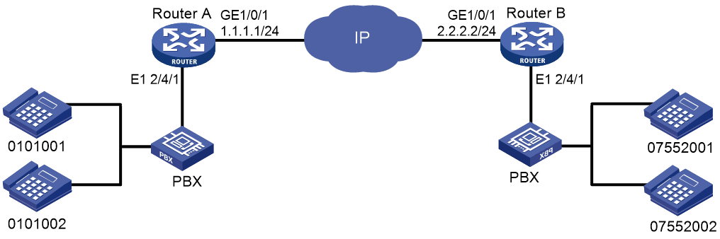
Procedure
1. Configure Router A:
# Configure the IP address 1.1.1.1/24 for interface GigabitEthernet 1/0/1.
<RouterA> system-view
[RouterA] interface gigabitethernet 1/0/1
[RouterA-GigabitEthernet1/0/1] ip address 1.1.1.1 255.255.255.0
[RouterA-GigabitEthernet1/0/1] quit
# Bundle the timeslots on interface E1 2/4/1 into a PRI set.
[RouterA] controller e1 2/4/1
[RouterA-E1 2/4/1] pri-set
[RouterA-E1 2/4/1] quit
# Configure the local number 0101001 for POTS entity 1001, and bind the digital voice interfaces line 2/4/1:15 to the POTS entity.
[RouterA] voice-setup
[RouterA-voice] dial-program
[RouterA-voice-dial] entity 1001 pots
[RouterA-voice-dial-entity1001] match-template 0101001
[RouterA-voice-dial-entity1001] line 2/4/1:15
[RouterA-voice-dial-entity1001] send-number all
[RouterA-voice-dial-entity1001] quit
# Configure the local number 0101002 for POTS entity 1002, and bind the digital voice interfaces line 2/4/1:15 to the POTS entity.
[RouterA-voice-dial] entity 1002 pots
[RouterA-voice-dial-entity1002] match-template 0101002
[RouterA-voice-dial-entity1002] line 2/4/1:15
[RouterA-voice-dial-entity1002] send-number all
[RouterA-voice-dial-entity1002] quit
# Configure the called number template 0755…. for VoIP entity 0755, and configure the destination IP address as 2.2.2.2.
[RouterA-voice-dial] entity 0755 voip
[RouterA-voice-dial-entity755] match-template 0755....
[RouterA-voice-dial-entity755] address ip 2.2.2.2
2. Configure Router B:
# Configure the IP address 2.2.2.2/24 for interface GigabitEthernet 1/0/1.
<RouterB> system-view
[RouterB] interface gigabitethernet 1/0/1
[RouterB-GigabitEthernet1/0/1] ip address 2.2.2.2 255.255.255.0
[RouterB-GigabitEthernet1/0/1] quit
# Bundle the timeslots on interface E1 2/4/1 into a PRI set.
[RouterB] controller e1 2/4/1
[RouterB-E1 2/4/1] pri-set
[RouterB-E1 2/4/1] quit
# Configure the local number 07552001 for POTS entity 2001, and bind the digital voice interfaces line 2/4/1:15 to the POTS entity.
[RouterB] voice-setup
[RouterB-voice] dial-program
[RouterB-voice-dial] entity 2001 pots
[RouterB-voice-dial-entity2001] match-template 07552001
[RouterB-voice-dial-entity2001] line 2/4/1:15
[RouterB-voice-dial-entity2001] send-number all
[RouterB-voice-dial-entity2001] quit
# Configure the local number 07552002 for POTS entity 2002, and bind the digital voice interfaces line 2/4/1:15 to the POTS entity.
[RouterB-voice-dial] entity 2002 pots
[RouterB-voice-dial-entity2002] match-template 07552002
[RouterB-voice-dial-entity2002] line 2/4/1:15
[RouterB-voice-dial-entity2002] send-number all
[RouterB-voice-dial-entity2002] quit
# Configure the called number template 010…. for VoIP entity 010, and configure the destination IP address as 1.1.1.1.
[RouterB-voice-dial] entity 010 voip
[RouterB-voice-dial-entity10] match-template 010....
[RouterB-voice-dial-entity10] address ip 1.1.1.1
Verifying the configuration
# Place a call from a telephone attached to Router A to a telephone attached to Router B to verify that the telephones can call each other through DSS1 signaling.
# Use the display voice subscriber-line command to display information about digital voice interfaces. (Details not shown.)
Example: Configuring BSV DSS1 signaling
Network configuration
As shown in Figure 22, the routers connect to the PBXs through BSV interfaces.
Configure DSS1 signaling on the routers so the telephones can call each other.
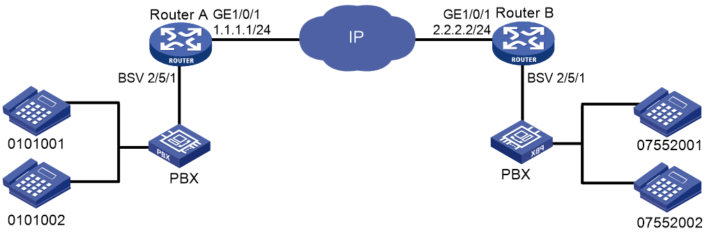
Procedure
1. Configure Router A:
# Configure the IP address 1.1.1.1/24 for interface GigabitEthernet 1/0/1.
<RouterA> system-view
[RouterA] interface gigabitethernet 1/0/1
[RouterA-GigabitEthernet1/0/1] ip address 1.1.1.1 255.255.255.0
[RouterA-GigabitEthernet1/0/1] quit
# Configure the local number 0101001 for POTS entity 1001, and bind the digital voice interfaces line 2/5/1 to the POTS entity.
[RouterA] voice-setup
[RouterA-voice] dial-program
[RouterA-voice-dial] entity 1001 pots
[RouterA-voice-dial-entity1001] match-template 0101001
[RouterA-voice-dial-entity1001] line 2/5/1
[RouterA-voice-dial-entity1001] send-number all
[RouterA-voice-dial-entity1001] quit
# Configure the local number 0101002 for POTS entity 1002, and bind the digital voice interfaces line 2/5/1 to the POTS entity.
[RouterA-voice-dial] entity 1002 pots
[RouterA-voice-dial-entity1002] match-template 0101002
[RouterA-voice-dial-entity1002] line 2/5/1
[RouterA-voice-dial-entity1002] send-number all
[RouterA-voice-dial-entity1002] quit
# Configure the called number template 0755…. for VoIP entity 0755, and configure the destination IP address as 2.2.2.2.
[RouterA-voice-dial] entity 0755 voip
[RouterA-voice-dial-entity755] match-template 0755....
[RouterA-voice-dial-entity755] address sip ip 2.2.2.2
2. Configure Router B:
# Configure the IP address 2.2.2.2/24 for interface GigabitEthernet 1/0/1.
<RouterB> system-view
[RouterB] interface gigabitethernet 1/0/1
[RouterB-GigabitEthernet1/0/1] ip address 2.2.2.2 255.255.255.0
[RouterB-GigabitEthernet1/0/1] quit
# Configure the local number 07552001 for POTS entity 2001, and bind the digital voice interfaces line 2/5/1 to the POTS entity.
[RouterB] voice-setup
[RouterB-voice] dial-program
[RouterB-voice-dial] entity 2001 pots
[RouterB-voice-dial-entity2001] match-template 07552001
[RouterB-voice-dial-entity2001] line 2/5/1
[RouterB-voice-dial-entity2001] send-number all
[RouterB-voice-dial-entity2001] quit
# Configure the local number 07552002 for POTS entity 2002, and bind the digital voice interfaces line 2/5/1 to the POTS entity.
[RouterB-voice-dial] entity 2002 pots
[RouterB-voice-dial-entity2002] match-template 07552002
[RouterB-voice-dial-entity2002] line 2/5/1
[RouterB-voice-dial-entity2002] send-number all
[RouterB-voice-dial-entity2002] quit
# Configure the called number template 010…. for VoIP entity 010, and configure the destination IP address as 1.1.1.1.
[RouterB-voice-dial] entity 010 voip
[RouterB-voice-dial-entity10] match-template 010....
[RouterB-voice-dial-entity10] address ip 1.1.1.1
Verifying the configuration
# Place a call from a telephone attached to Router A to a telephone attached to Router B to verify that the telephones can call each other through DSS1 signaling.
# Use the display voice subscriber-line command to display information about digital voice interfaces. (Details not shown.)
