- Table of Contents
- Related Documents
-
| Title | Size | Download |
|---|---|---|
| 01-ACL configuration | 186.42 KB |
Contents
Restrictions: Hardware compatibility with ACL
Restrictions and guidelines: ACL configuration
Restrictions and guidelines for basic ACL configuration
Restrictions and guidelines for advanced ACL configuration
Configuring an IPv4 advanced ACL
Configuring an IPv6 advanced ACL
Configuring packet filtering with ACLs
About packet filtering with ACLs
Applying an ACL to an interface for packet filtering
Applying an ACL to a zone pair for packet filtering
Configuring logging and SNMP notifications for packet filtering
Setting the packet filtering default action
Display and maintenance commands for ACL
Example: Configuring an interface-based packet filter
Example: Configuring a zone pair-based packet filter
Configuring ACLs
About ACLs
An access control list (ACL) is a set of rules for identifying traffic based on criteria such as source IP address, destination IP address, and port number. The rules are also called permit or deny statements.
ACLs are primarily used for packet filtering. You can also use ACLs in QoS, security, routing, and other modules for identifying traffic. The packet drop or forwarding decisions depend on the modules that use ACLs.
Numbering and naming ACLs
When creating an ACL, you must assign it a number or name for identification. You can specify an existing ACL by its number or name. Each ACL type has a unique range of ACL numbers.
For basic or advanced ACLs with the same number, you must use the ipv6 keyword to distinguish them. For ACLs with the same name, you must use the ipv6 and mac keywords to distinguish them.
ACL types
|
Type |
ACL number |
IP version |
Match criteria |
|
Basic ACLs |
2000 to 2999 |
IPv4 |
Source IPv4 address. |
|
IPv6 |
Source IPv6 address. |
||
|
Advanced ACLs |
3000 to 3999 |
IPv4 |
Source IPv4 address, destination IPv4 address, packet priority, protocol number, and other Layer 3 and Layer 4 header fields. |
|
IPv6 |
Source IPv6 address, destination IPv6 address, packet priority, protocol number, and other Layer 3 and Layer 4 header fields. |
||
|
Layer 2 ACLs |
4000 to 4999 |
IPv4 and IPv6 |
Layer 2 header fields, such as source and destination MAC addresses, 802.1p priority, and link layer protocol type. |
Match order
The rules in an ACL are sorted in a specific order. When a packet matches a rule, the device stops the match process and performs the action defined in the rule. If an ACL contains overlapping or conflicting rules, the matching result and action to take depend on the rule order.
The following ACL match orders are available:
· config—Sorts ACL rules in ascending order of rule ID. A rule with a lower ID is matched before a rule with a higher ID. If you use this method, check the rules and their order carefully.
· auto—Sorts ACL rules in depth-first order. Depth-first ordering makes sure any subset of a rule is always matched before the rule. Table 1 lists the sequence of tie breakers that depth-first ordering uses to sort rules for each type of ACL.
Table 1 Sort ACL rules in depth-first order
|
ACL type |
Sequence of tie breakers |
|
IPv4 basic ACL |
1. VPN instance. 2. More 0s in the source IPv4 address wildcard (more 0s means a narrower IPv4 address range). 3. Rule configured earlier. |
|
IPv4 advanced ACL |
1. VPN instance. 2. Specific protocol number. 3. More 0s in the source IPv4 address wildcard mask. 4. More 0s in the destination IPv4 address wildcard. 5. Narrower TCP/UDP service port number range. 6. Rule configured earlier. |
|
IPv6 basic ACL |
1. VPN instance. 2. Longer prefix for the source IPv6 address (a longer prefix means a narrower IPv6 address range). 3. Rule configured earlier. |
|
IPv6 advanced ACL |
1. VPN instance. 2. Specific protocol number. 3. Longer prefix for the source IPv6 address. 4. Longer prefix for the destination IPv6 address. 5. Narrower TCP/UDP service port number range. 6. Rule configured earlier. |
|
Layer 2 ACL |
1. More 1s in the source MAC address mask (more 1s means a smaller MAC address). 2. More 1s in the destination MAC address mask. 3. Rule configured earlier. |
A wildcard mask, also called an inverse mask, is a 32-bit binary number represented in dotted decimal notation. In contrast to a network mask, the 0 bits in a wildcard mask represent "do care" bits, and the 1 bits represent "don't care" bits. If the "do care" bits in an IP address are identical to the "do care" bits in an IP address criterion, the IP address matches the criterion. All "don't care" bits are ignored. The 0s and 1s in a wildcard mask can be noncontiguous. For example, 0.255.0.255 is a valid wildcard mask.
Rule numbering
ACL rules can be manually numbered or automatically numbered. This section describes how automatic ACL rule numbering works.
Rule numbering step
If you do not assign an ID to the rule you are creating, the system automatically assigns it a rule ID. The rule numbering step sets the increment by which the system automatically numbers rules. For example, the default ACL rule numbering step is 5. If you do not assign IDs to rules you are creating, they are automatically numbered 0, 5, 10, 15, and so on. The wider the numbering step, the more rules you can insert between two rules.
By introducing a gap between rules rather than contiguously numbering rules, you have the flexibility of inserting rules in an ACL. This feature is important for a config-order ACL, where ACL rules are matched in ascending order of rule ID.
The rule numbering step sets the increment by which the system numbers rules automatically. If you do not specify a rule ID when creating an ACL rule, the system automatically assigns it a rule ID. This rule ID is the nearest higher multiple of the numbering step to the current highest rule ID, starting from the start rule ID. For example, if the rule numbering step is 5 and the current highest rule ID is 12, the rule is numbered 15.
The wider the numbering step, the more rules you can insert between two rules. Whenever the step or start rule ID changes, the rules are renumbered, starting from the start rule ID. For example, if there are five rules numbered 0, 5, 9, 10, and 15, changing the step from 5 to 2 causes the rules to be renumbered 0, 2, 4, 6, and 8.
Automatic rule numbering and renumbering
The ID automatically assigned to an ACL rule takes the nearest higher multiple of the numbering step to the current highest rule ID, starting with 0.
For example, if the step is 5, and there are five rules numbered 0, 5, 9, 10, and 12, the newly defined rule is numbered 15. If the ACL does not contain a rule, the first rule is numbered 0.
Whenever the step changes, the rules are renumbered, starting from 0. For example, changing the step from 5 to 2 renumbers rules 5, 10, 13, and 15 as rules 0, 2, 4, and 6.
For an ACL of the match order auto, rules are sorted in depth-first order, and are renumbered based on the match order. For example, rules are in the match order of 0, 10, and 5. Changing the numbering step to 2 renumbers rules 0, 10, and 5 (not 0, 5, and 10) as rules 0, 2, 4
Fragment filtering with ACLs
Traditional packet filtering matches only first fragments of packets, and allows all subsequent non-first fragments to pass through. Attackers can fabricate non-first fragments to attack networks.
To avoid risks, the ACL feature is designed as follows:
· Filters all fragments by default, including non-first fragments.
· Allows for matching criteria modification for efficiency. For example, you can configure the ACL to filter only non-first fragments.
Restrictions: Hardware compatibility with ACL
The following compatibility matrixes show the support of hardware platforms for WLAN-related commands and parameters:
|
Hardware |
Command and parameter compatibility |
|
MSR810, MSR810-W, MSR810-W-DB, MSR810-LM, MSR810-W-LM, MSR810-10-PoE, MSR810-LM-HK, MSR810-W-LM-HK, MSR810-LM-CNDE-SJK, MSR810-CNDE-SJK |
Yes |
|
MSR810-LMS, MSR810-LUS |
Yes |
|
MSR810-LMS-EA, MSR810-LME |
Yes |
|
MSR1004S-5G |
Yes |
|
MSR2600-6-X1, MSR2600-10-X1, MSR2600-15-X1 |
Yes |
|
MSR 2630 |
Yes |
|
MSR3600-28, MSR3600-51 |
Yes |
|
MSR3600-28-SI, MSR3600-51-SI |
No |
|
MSR3600-28-X1, MSR3600-28-X1-DP, MSR3600-51-X1, MSR3600-51-X1-DP |
Yes |
|
MSR3610-I-DP, MSR3610-IE-DP, MSR3610-IE-ES, MSR3610-IE-EAD, MSR-EAD-AK770, MSR3610-I-IG, MSR3610-IE-IG |
Yes |
|
MSR3610-X1, MSR3610-X1-DP, MSR3610-X1-DC, MSR3610-X1-DP-DC, MSR3620-X1, MSR3640-X1 |
Yes |
|
MSR 3610, MSR 3620, MSR 3620-DP, MSR 3640, MSR 3660 |
Yes |
|
MSR3610-G, MSR3620-G |
No |
|
MSR3640-X1-HI |
Yes |
|
Hardware |
Command and parameter compatibility |
|
MSR810-W-WiNet, MSR810-LM-WiNet |
Yes |
|
MSR830-4LM-WiNet |
Yes |
|
MSR830-5BEI-WiNet, MSR830-6EI-WiNet, MSR830-10BEI-WiNet |
Yes |
|
MSR830-6BHI-WiNet, MSR830-10BHI-WiNet |
Yes |
|
MSR2600-6-WiNet, MSR2600-10-X1-WiNet |
Yes |
|
MSR2630-WiNet |
Yes |
|
MSR3600-28-WiNet |
Yes |
|
MSR3610-X1-WiNet |
Yes |
|
MSR3610-WiNet, MSR3620-10-WiNet, MSR3620-DP-WiNet, MSR3620-WiNet, MSR3660-WiNet |
Yes |
|
Hardware |
Command and parameter compatibility |
|
MSR2630-XS |
Yes |
|
MSR3600-28-XS |
Yes |
|
MSR3610-XS |
Yes |
|
MSR3620-XS |
Yes |
|
MSR3610-I-XS |
Yes |
|
MSR3610-IE-XS |
Yes |
|
MSR3620-X1-XS |
Yes |
|
MSR3640-XS |
Yes |
|
MSR3660-XS |
Yes |
|
Hardware |
Command and parameter compatibility |
|
MSR810-LM-GL |
Yes |
|
MSR810-W-LM-GL |
Yes |
|
MSR830-6EI-GL |
Yes |
|
MSR830-10EI-GL |
Yes |
|
MSR830-6HI-GL |
Yes |
|
MSR830-10HI-GL |
Yes |
|
MSR1004S-5G-GL |
Yes |
|
MSR2600-6-X1-GL |
Yes |
|
MSR3600-28-SI-GL |
No |
Restrictions and guidelines: ACL configuration
· If you create a numbered ACL, you can enter the view of the ACL by using the following commands:
¡ acl [ ipv6 ] number acl-number
¡ acl { [ ipv6 ] { advanced | basic } | mac } acl-number
· If you create a ACL by specifying both a number and a name, you can enter the view of the ACL by using the following commands:
¡ acl [ ipv6 ] number acl-number (only for basic and advanced ACLs)
¡ acl [ ipv6 ] number acl-number [ name acl-name ]
¡ acl { [ ipv6 ] { advanced | basic } | mac } name acl-name
· If you create a named ACL by using the acl { [ ipv6 ] { advanced | basic } | mac } name acl-name command, you can enter the view of the ACL by using the following commands:
¡ acl [ ipv6 ] name acl-name
¡ acl { [ ipv6 ] { advanced | basic } | mac } name acl-name
· Matching packets are forwarded through slow forwarding if an ACL rule contains match criteria or has functions enabled in addition to the following match criteria and functions:
¡ Source and destination IP addresses.
¡ Source and destination ports.
¡ Transport layer protocol.
¡ ICMP or ICMPv6 message type, message code, and message name.
¡ VPN instance.
¡ Logging.
¡ Time range.
Slow forwarding requires packets to be sent to the control plane for forwarding entry calculation, which affects the device forwarding performance.
ACL tasks at a glance
To configure an ACL, perform the following tasks:
· Configure ACLs according to the characteristics of the packets to be matched
· (Optional.) Copying an ACL
· (Optional.) Enabling ACL acceleration
· (Optional.) Configuring packet filtering with ACLs
Configuring a basic ACL
About basic ACLs
Basic ACLs match packets based only on source IP addresses.
Restrictions and guidelines for basic ACL configuration
The logging keyword specified in an ACL rule enables the ACL module to send log messages to the information center.
With the information center, you can set log message filtering and output rules, including output destinations.
The information center can output ACL logs to any destinations except the console and the monitor terminal. If you configure the console or monitor terminal as an output destination, the output destination setting will not take effect.
To view ACL logs stored on the device, use the display logbuffer command. Make sure you do not disable log output to the log buffer, which is enabled by default.
For more information about configuring the information center, see Network Management and Monitoring Configuration Guide.
Configuring an IPv4 basic ACL
1. Enter system view.
system-view
2. Create an IPv4 basic ACL and enter its view. Choose one option as needed:
¡ Create an IPv4 basic ACL by specifying an ACL number.
acl number acl-number [ name acl-name ] [ match-order { auto | config } ]
¡ Create an IPv4 basic ACL by specifying the basic keyword.
acl basic { acl-number | name acl-name } [ match-order { auto | config } ]
3. (Optional.) Configure a description for the IPv4 basic ACL.
description text
By default, an IPv4 basic ACL does not have a description.
4. (Optional.) Set the rule numbering step.
step step-value
By default, the rule numbering step is 5 and the start rule ID is 0.
5. Create or edit a rule.
rule [ rule-id ] { deny | permit } [ counting | fragment | logging | source { object-group address-group-name | source-address source-wildcard | any } | time-range time-range-name | vpn-instance vpn-instance-name ] *
The logging keyword takes effect only when the module (for example, packet filtering) that uses the ACL supports logging.
6. (Optional.) Add or edit a rule comment.
rule rule-id comment text
By default, no rule comment is configured.
Configuring an IPv6 basic ACL
1. Enter system view.
system-view
2. Create an IPv6 basic ACL view and enter its view. Choose one option as needed:
¡ Create an IPv6 basic ACL by specifying an ACL number.
acl ipv6 number acl-number [ name acl-name ] [ match-order { auto | config } ]
¡ Create an IPv6 basic ACL by specifying the basic keyword.
acl ipv6 basic { acl-number | name acl-name } [ match-order { auto | config } ]
3. (Optional.) Configure a description for the IPv6 basic ACL.
description text
By default, an IPv6 basic ACL does not have a description.
4. (Optional.) Set the rule numbering step.
step step-value
By default, the rule numbering step is 5 and the start rule ID is 0.
5. Create or edit a rule.
rule [ rule-id ] { deny | permit } [ counting | fragment | logging | routing [ type routing-type ] | source { object-group address-group-name | source-address source-prefix | source-address/source-prefix | any } | time-range time-range-name | vpn-instance vpn-instance-name ] *
The logging keyword takes effect only when the module (for example, packet filtering) that uses the ACL supports logging.
6. (Optional.) Add or edit a rule comment.
rule rule-id comment text
By default, no rule comment is configured.
Configuring an advanced ACL
About advanced ACLs
Advanced ACLs match packets based on the following criteria:
· Source IP addresses.
· Destination IP addresses.
· Packet priorities.
· Local QoS IDs.
· Protocol types.
· Other protocol header information, such as TCP/UDP source and destination port numbers, TCP flags, ICMP message types, and ICMP message codes.
Compared to basic ACLs, advanced ACLs allow more flexible and accurate filtering.
Restrictions and guidelines for advanced ACL configuration
The logging keyword specified in an ACL rule enables the ACL module to send log messages to the information center.
With the information center, you can set log message filtering and output rules, including output destinations.
The information center can output ACL logs to any destinations except the console and the monitor terminal. If you configure the console or monitor terminal as an output destination, the output destination setting will not take effect.
To view ACL logs stored on the device, use the display logbuffer command. Make sure you do not disable log output to the log buffer, which is enabled by default.
For more information about configuring the information center, see Network Management and Monitoring Configuration Guide.
Configuring an IPv4 advanced ACL
1. Enter system view.
system-view
2. Create an IPv4 advanced ACL and enter its view. Choose one option as needed:
¡ Create a numbered IPv4 advanced ACL by specifying an ACL number.
acl number acl-number [ name acl-name ] [ match-order { auto | config } ]
¡ Create an IPv4 advanced ACL by specifying the advanced keyword.
acl advanced { acl-number | name acl-name } [ match-order { auto | config } ]
3. (Optional.) Configure a description for the IPv4 advanced ACL.
description text
By default, an IPv4 advanced ACL does not have a description.
4. (Optional.) Set the rule numbering step.
step step-value
By default, the rule numbering step is 5 and the start rule ID is 0.
5. Create or edit a rule.
rule [ rule-id ] { deny | permit } protocol [ { { ack ack-value | fin fin-value | psh psh-value | rst rst-value | syn syn-value | urg urg-value } * | established } | counting | destination { object-group address-group-name | dest-address dest-wildcard | any } | destination-port { object-group port-group-name | operator port1 [ port2 ] } | { dscp dscp1 [ to dscp2 ] | { precedence precedence | tos tos } * } | fragment | icmp-type { icmp-type [ icmp-code ] | icmp-message } | logging | source { object-group address-group-name | source-address source-wildcard | any } | source-port { object-group port-group-name | operator port1 [ port2 ] } | time-range time-range-name | ttl operator ttl-value1 [ ttl-value2 ] | vpn-instance vpn-instance-name ] *
The logging keyword takes effect only when the module (for example, packet filtering) that uses the ACL supports logging.
6. (Optional.) Add or edit a rule comment.
rule rule-id comment text
By default, no rule comment is configured.
Configuring an IPv6 advanced ACL
1. Enter system view.
system-view
2. Create an IPv6 advanced ACL and enter its view. Choose one option as needed:
¡ Create a numbered IPv6 advanced ACL by specifying an ACL number.
acl ipv6 number acl-number [ name acl-name ] [ match-order { auto | config } ]
¡ Create an IPv6 advanced ACL by specifying the advanced keyword.
acl ipv6 advanced { acl-number | name acl-name } [ match-order { auto | config } ]
3. (Optional.) Configure a description for the IPv6 advanced ACL.
description text
By default, an IPv6 advanced ACL does not have a description.
4. (Optional.) Set the rule numbering step.
step step-value
By default, the rule numbering step is 5 and the start rule ID is 0.
5. Create or edit a rule.
rule [ rule-id ] { deny | permit } protocol [ { { ack ack-value | fin fin-value | psh psh-value | rst rst-value | syn syn-value | urg urg-value } * | established } | counting | destination { object-group address-group-name | dest-address dest-prefix | dest-address/dest-prefix | any } | destination-port { object-group port-group-name | operator port1 [ port2 ] } | dscp dscp | flow-label flow-label-value | fragment | icmp6-type { icmp6-type icmp6-code | icmp6-message } | logging | routing [ type routing-type ] | hop-by-hop [ type hop-type ] | source { object-group address-group-name | source-address source-prefix | source-address/source-prefix | any } | source-port { object-group port-group-name | operator port1 [ port2 ] } | time-range time-range-name | ttl operator ttl-value1 [ ttl-value2 ] | vpn-instance vpn-instance-name ] *
The logging keyword takes effect only when the module (for example, packet filtering) that uses the ACL supports logging.
6. (Optional.) Add or edit a rule comment.
rule rule-id comment text
By default, no rule comment is configured.
Configuring a Layer 2 ACL
About this task
Layer 2 ACLs, also called Ethernet frame header ACLs, match packets based on Layer 2 Ethernet header fields, such as:
· Source MAC address.
· Destination MAC address.
· 802.1p priority (VLAN priority).
· Link layer protocol type.
· Encapsulation type.
Procedure
1. Enter system view.
system-view
2. Create a Layer 2 ACL and enter its view. Choose one option as needed:
¡ Create a Layer 2 ACL by specifying an ACL number.
acl number acl-number [ name acl-name ] [ match-order { auto | config } ]
¡ Create a Layer 2 ACL by specifying the mac keyword.
acl mac { acl-number | name acl-name } [ match-order { auto | config } ]
3. (Optional.) Configure a description for the Layer 2 ACL.
description text
By default, a Layer 2 ACL does not have a description.
4. (Optional.) Set the rule numbering step.
step step-value
By default, the rule numbering step is 5 and the start rule ID is 0.
5. Create or edit a rule.
rule [ rule-id ] { deny | permit } [ cos dot1p | counting | dest-mac dest-address dest-mask | { lsap lsap-type lsap-type-mask | type protocol-type protocol-type-mask } | source-mac source-address source-mask | time-range time-range-name ] *
6. (Optional.) Add or edit a rule comment.
rule rule-id comment text
By default, no rule comment is configured.
Copying an ACL
About this task
You can create an ACL by copying an existing ACL (source ACL). The new ACL (destination ACL) has the same properties and content as the source ACL, but uses a different number or name than the source ACL.
Restrictions and guidelines
To successfully copy an ACL, make sure:
· The destination ACL is the same type as the source ACL.
· The source ACL already exists, but the destination ACL does not.
Procedure
1. Enter system view.
system-view
2. Copy an existing ACL to create a new ACL.
acl [ ipv6 | mac ] copy { source-acl-number | name source-acl-name } to { dest-acl-number | name dest-acl-name }
Enabling ACL acceleration
About this task
ACL acceleration speeds up ACL rule lookup. The acceleration effect increases with the number of ACL rules. For example, when a large ACL is used for a session-based service, such as NAT or ASPF, ACL acceleration can avoid session timeouts caused by ACL processing delays.
ACL acceleration is delayed for a period after an ACL rule is added, deleted, or modified. If additional rule changes occur during the delay period, the delay period starts to count again. If an ACL contains 100 or less rules, the delay period is 2 seconds. If an ACL contains more than 100 rules, the delay period is 20 seconds.
Procedure
1. Enter system view.
system-view
2. Create an ACL and enter ACL view.
acl { [ ipv6 ] { advanced | basic } { acl-number | name acl-name } | mac { acl-number | name acl-name } } [ match-order { auto | config } ]
3. Enable ACL acceleration for the ACL.
accelerate
By default, ACL acceleration is disabled.
|
|
CAUTION: If a large number of ACL rules exist, executing the undo accelerate command might cause the device to reach the severe CPU usage alarm threshold, which affects normal service processing. |
Configuring packet filtering with ACLs
About packet filtering with ACLs
This section describes procedures for using an ACL to filtering packets. For example, you can apply an ACL to an interface to filter incoming or outgoing packets.
Applying an ACL to an interface for packet filtering
Restrictions and guidelines
You can apply a maximum of 32 ACLs to the same direction of an interface.
Procedure
1. Enter system view.
system-view
2. Enter interface view.
interface interface-type interface-number
3. Apply an ACL to the interface to filter packets.
packet-filter [ ipv6 | mac ] { acl-number | name acl-name } { inbound | outbound }
By default, an interface does not filter packets.
Applying an ACL to a zone pair for packet filtering
Restrictions and guidelines
You can apply a maximum of 32 ACLs to the same zone pair. For more information about zone pairs, see Security Configuration Guide.
Procedure
1. Enter system view.
system-view
2. Enter zone pair view.
zone-pair security source source-zone-name destination destination-zone-name
3. Apply an ACL to the zone pair to filter packets.
packet-filter [ ipv6 ] { acl-number | name acl-name }
By default, a zone pair does not filter packets.
Configuring logging and SNMP notifications for packet filtering
About this task
You can configure the ACL module to generate log entries or SNMP notifications for packet filtering and output them to the information center or SNMP module at the output interval. The log entry or notification records the number of matching packets and the matched ACL rules. When the first packet of a flow matches an ACL rule, the output interval starts, and the device immediately outputs a log entry or notification for this packet. When the output interval ends, the device outputs a log entry or notification for subsequent matching packets of the flow.
For more information about the information center, see Network Management and Monitoring Configuration Guide.
For more information about SNMP, see Network Management and Monitoring Configuration Guide.
Procedure
1. Enter system view.
system-view
2. Set the interval for outputting packet filtering logs or notifications.
acl { logging | trap } interval interval
The default setting is 0 minutes. By default, the device does not generate log entries or SNMP notifications for packet filtering.
Setting the packet filtering default action
About this task
By default, the packet filter permits packets that do not match any ACL rule to pass. Perform this task to deny packets that do not match any ACL rule. The packet filtering default action does not take effect on zone pair packet filtering. The default action for zone pair packet filtering is always deny.
Procedure
1. Enter system view.
system-view
2. Set the packet filtering default action to deny.
packet-filter default deny
By default, the packet filter permits packets that do not match any ACL rule to pass.
Display and maintenance commands for ACL
Execute display commands in any view and reset commands in user view.
|
Task |
Command |
|
Display ACL configuration and match statistics. |
display acl [ ipv6 | mac ] { acl-number | all | name acl-name } |
|
Display ACL acceleration status. |
In standalone mode: display acl accelerate { summary [ ipv6 | mac ] | verbose [ ipv6 | mac ] { acl-number | name acl-name } } In IRF mode: display acl accelerate { summary [ ipv6 | mac ] | verbose [ ipv6 | mac ] { acl-number | name acl-name } slot slot-number } |
|
Display ACL application information for packet filtering. |
In standalone mode: display packet-filter { interface [ interface-type interface-number ] [ inbound | outbound ] | zone-pair security [ source source-zone-name destination destination-zone-name ] } In IRF mode: display packet-filter { interface [ interface-type interface-number ] [ inbound | outbound ] | zone-pair security [ source source-zone-name destination destination-zone-name ] } [ slot slot-number ] |
|
Display match statistics for packet filtering ACLs. |
display packet-filter statistics { interface interface-type interface-number { inbound | outbound } [ default | [ ipv6 | mac ] { acl-number | name acl-name } ] | zone-pair security source source-zone-name destination destination-zone-name [ [ ipv6 ] { acl-number | name acl-name } ] } [ brief ] |
|
Display the accumulated statistics for packet filtering ACLs. |
display packet-filter statistics sum { inbound | outbound } [ ipv6 | mac ] { acl-number | name acl-name } [ brief ] |
|
Display detailed ACL packet filtering information. |
In standalone mode: display packet-filter verbose { interface interface-type interface-number { inbound | outbound } [ [ ipv6 | mac ] { acl-number | name acl-name } ] | zone-pair security source source-zone-name destination destination-zone-name [ [ ipv6 ] { acl-number | name acl-name } ] } In IRF mode: display packet-filter verbose { interface interface-type interface-number { inbound | outbound } [ [ ipv6 | mac ] { acl-number | name acl-name } ] | zone-pair security source source-zone-name destination destination-zone-name [ [ ipv6 ] { acl-number | name acl-name } ] } [ slot slot-number ] |
|
Clear ACL statistics. |
reset acl [ ipv6 | mac ] counter { acl-number | all | name acl-name } |
|
Clear match statistics for packet filtering ACLs. |
reset packet-filter statistics { interface [ interface-type interface-number ] { inbound | outbound } [ default | [ ipv6 | mac ] { acl-number | name acl-name } ] | zone-pair security [ source source-zone-name destination destination-zone-name ] [ ipv6 ] { acl-number | name acl-name } } |
ACL configuration examples
Example: Configuring an interface-based packet filter
Network configuration
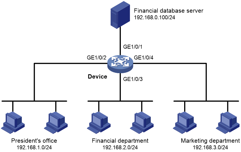
A company interconnects its departments through the device. Configure a packet filter to:
· Permit access from the President's office at any time to the financial database server.
· Permit access from the Finance department to the database server only during working hours (from 8:00 to 18:00) on working days.
· Deny access from any other department to the database server.
Figure 1 Network diagram
Procedure
# Create a periodic time range from 8:00 to 18:00 on working days.
<Device> system-view
[Device] time-range work 08:0 to 18:00 working-day
# Create an IPv4 advanced ACL numbered 3000.
[Device] acl advanced 3000
# Configure a rule to permit access from the President's office to the financial database server.
[Device-acl-ipv4-adv-3000] rule permit ip source 192.168.1.0 0.0.0.255 destination 192.168.0.100 0
# Configure a rule to permit access from the Finance department to the database server during working hours.
[Device-acl-ipv4-adv-3000] rule permit ip source 192.168.2.0 0.0.0.255 destination 192.168.0.100 0 time-range work
# Configure a rule to deny access to the financial database server.
[Device-acl-ipv4-adv-3000] rule deny ip source any destination 192.168.0.100 0
[Device-acl-ipv4-adv-3000] quit
# Apply IPv4 advanced ACL 3000 to filter outgoing packets on interface GigabitEthernet 1/0/1.
[Device] interface gigabitethernet 1/0/1
[Device-GigabitEthernet1/0/1] packet-filter 3000 outbound
[Device-GigabitEthernet1/0/1] quit
Verifying the configuration
# Verify that a PC in the Finance department can ping the database server during working hours. (All PCs in this example use Windows XP).
C:\> ping 192.168.0.100
Pinging 192.168.0.100 with 32 bytes of data:
Reply from 192.168.0.100: bytes=32 time=1ms TTL=255
Reply from 192.168.0.100: bytes=32 time<1ms TTL=255
Reply from 192.168.0.100: bytes=32 time<1ms TTL=255
Reply from 192.168.0.100: bytes=32 time<1ms TTL=255
Ping statistics for 192.168.0.100:
Packets: Sent = 4, Received = 4, Lost = 0 (0% loss),
Approximate round trip times in milli-seconds:
Minimum = 0ms, Maximum = 1ms, Average = 0ms
# Verify that a PC in the Marketing department cannot ping the database server during working hours.
C:\> ping 192.168.0.100
Pinging 192.168.0.100 with 32 bytes of data:
Request timed out.
Request timed out.
Request timed out.
Request timed out.
Ping statistics for 192.168.0.100:
Packets: Sent = 4, Received = 0, Lost = 4 (100% loss),
# Display configuration and match statistics for IPv4 advanced ACL 3000 on the device during working hours.
[Device] display acl 3000
Advanced IPv4 ACL 3000, 3 rules,
ACL's step is 5
rule 0 permit ip source 192.168.1.0 0.0.0.255 destination 192.168.0.100 0
rule 5 permit ip source 192.168.2.0 0.0.0.255 destination 192.168.0.100 0 time-range work (4 times matched) (Active)
rule 10 deny ip destination 192.168.0.100 0 (4 times matched)
The output shows that rule 5 is active. Rule 5 and rule 10 have been matched four times as the result of the ping operations.
Example: Configuring a zone pair-based packet filter
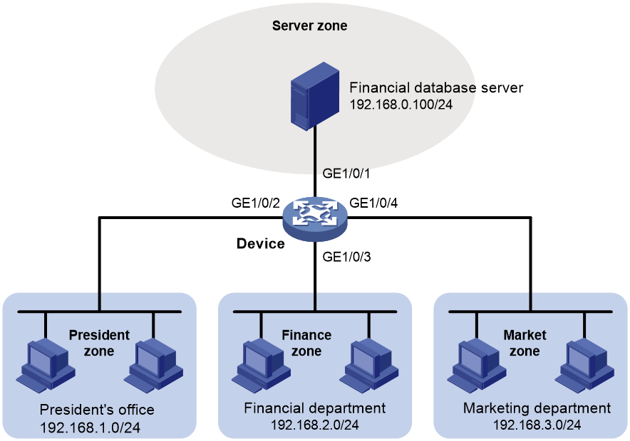
Network configuration
A company interconnects its departments through the device. The financial database server, President's office, Finance department, and Marketing department belong to different security zones. Configure a packet filter to:
· Permit access from the President's office at any time to the financial database server.
· Permit access from the Finance department to the financial database server only during working hours (from 8:00 to 18:00) on working days.
· Deny access from any other department to the financial database server.
Figure 2 Network diagram
Procedure
# Create security zone Server, and add interface GigabitEthernet 1/0/1 to the security zone.
<Device> system-view
[Device] security-zone name Server
[Device-security-zone-Server] import interface gigabitethernet 1/0/1
[Device-security-zone-Server] quit
# Create security zone President, and add interface GigabitEthernet 1/0/2 to the security zone.
[Device] security-zone name President
[Device-security-zone-President] import interface gigabitethernet 1/0/2
[Device-security-zone-President] quit
# Create security zone Finance, and add interface GigabitEthernet 1/0/3 to the security zone.
[Device] security-zone name Finance
[Device-security-zone-Finance] import interface gigabitethernet 1/0/3
[Device-security-zone-Finance] quit
# Create security zone Market, and add interface GigabitEthernet 1/0/4 to the security zone.
[Device] security-zone name Market
[Device-security-zone-Market] import interface gigabitethernet 1/0/4
[Device-security-zone-Market] quit
# Create a periodic time range from 8:00 to 18:00 on working days.
[Device] time-range work 08:0 to 18:00 working-day
# Configure ACL 3000 to permit access from the President's office at any time to the financial database server.
[Device] acl advanced 3000
[Device-acl-ipv4-adv-3000] rule permit ip source 192.168.1.0 0.0.0.255 destination 192.168.0.100 0
[Device-acl-ipv4-adv-3000] quit
# Configure ACL 3001 to permit access from the Finance department to the financial database server only during working hours on working days.
[Device] acl advanced 3001
[Device-acl-ipv4-adv-3001] rule permit ip source 192.168.2.0 0.0.0.255 destination 192.168.0.100 0 time-range work
[Device-acl-ipv4-adv-3001] quit
# Configure ACL 3002 to deny access from any other department to the financial database server.
[Device] acl advanced 3002
[Device-acl-ipv4-adv-3002] rule deny ip source any destination 192.168.0.100 0
[Device-acl-ipv4-adv-3002] quit
# Create a zone pair with the source security zone President and destination security zone Server. Apply ACL 3000 to the zone pair for packet filtering.
[Device] zone-pair security source president destination server
[Device-zone-pair-security-President-Server] packet-filter 3000
[Device-zone-pair-security-President-Server] quit
# Create a zone pair with the source security zone Finance and destination security zone Server. Apply ACL 3001 to the zone pair for packet filtering.
[Device] zone-pair security source finance destination server
[Device-zone-pair-security-Finance-Server] packet-filter 3001
[Device-zone-pair-security-President-Server] quit
# Create a zone pair with the source security zone Market and destination security zone Server. Apply ACL 3002 to the zone pair for packet filtering.
[Device] zone-pair security source market destination server
[Device-zone-pair-security-Market-Server] packet-filter 3002
[Device-zone-pair-security-Market-Server] quit
Verifying the configuration
# Verify that a PC in the Finance department can ping the database server during working hours. (All PCs in this example use Windows XP).
C:\> ping 192.168.0.100
Pinging 192.168.0.100 with 32 bytes of data:
Reply from 192.168.0.100: bytes=32 time=1ms TTL=255
Reply from 192.168.0.100: bytes=32 time<1ms TTL=255
Reply from 192.168.0.100: bytes=32 time<1ms TTL=255
Reply from 192.168.0.100: bytes=32 time<1ms TTL=255
Ping statistics for 192.168.0.100:
Packets: Sent = 4, Received = 4, Lost = 0 (0% loss),
Approximate round trip times in milli-seconds:
Minimum = 0ms, Maximum = 1ms, Average = 0ms
# Verify that a PC in the Marketing department cannot ping the database server during working hours.
C:\> ping 192.168.0.100
Pinging 192.168.0.100 with 32 bytes of data:
Request timed out.
Request timed out.
Request timed out.
Request timed out.
Ping statistics for 192.168.0.100:
Packets: Sent = 4, Received = 0, Lost = 4 (100% loss),
# Display configuration and match statistics for IPv4 advanced ACL 3001 and 3002 on the device during working hours.
[Device] display acl 3001
Advanced IPv4 ACL 3001, 2 rules,
ACL's step is 5
rule 0 permit ip source 192.168.2.0 0.0.0.255 destination 192.168.0.100 0 time-range work (4 times matched) (Active)
[Device] display acl 3002
Advanced IPv4 ACL 3002, 1 rule,
ACL's step is 5
rule 0 deny ip destination 192.168.0.100 0 (4 times matched)
The output shows that the rule in ACL 3001 is active. ACL 3001 and ACL 3002 both have been matched four times as the result of the ping operations.
