- Table of Contents
- Related Documents
-
| Title | Size | Download |
|---|---|---|
| 04-ISDN configuration | 271.20 KB |
Contents
ISDN BRI interface tasks at a glance
ISDN PRI interface tasks at a glance
Setting the ISDN switch type on an ISDN interface
Setting the ISDN functionality of an ISDN interface
Configuring SPID parameters for the NI switch type
About configuring SPID parameters for the NI switch type
Configuring dynamic SPID negotiation
Configuring static SPID assignment
Enabling NIT mode for NI-type switches incapable of SPID negotiation
Configuring Q.931 negotiation parameters
Configuring Q.931 call control parameters
Configuring B-channel selection
Configuring calling number verification for incoming calls
Configuring called-number verification for incoming calls
Configuring ISDN calling number identification
Configuring the Q.921 operating parameters
Configuring the data link type of a BRI interface
Configuring per-channel TEI assignment on a BRI interface
Configuring the leased line service for an ISDN BRI interface
Enabling permanent Q.921 link connectivity on an BRI interface
Enabling persistent Layer 1 activation on a BRI interface
Configuring a BRI interface to supply line power
Configuring the sliding window size on an ISDN BRI interface
Configuring the sliding window size on an ISDN PRI interface
Display and maintenance commands for ISDN
Example: Configuring NI-enabled ISDN BRI
Configuring ISDN
About ISDN
Integrated Services Digital Network (ISDN) is a circuit-switched telephone network system that provides high-quality end-to-end digital connectivity at high rates over copper wire.
ISDN transmits all information in the digital form. It enables a single pair of telephone wires to transmit data and voice simultaneously at high rates. This feature enables ISDN to provide more services and higher transmission efficiency than PSTN, where information is transmitted in the analog form.
ISDN provides a set of standard multipurpose user-network interfaces (UNIs). Different services and terminals can use the same UNI interface to access an ISDN network.
ISDN interfaces
ISDN uses TDM technology to divide a physical interface into one data (D) signaling channel and multiple bearer (B) channels.
· The D-channel transmits control signaling.
· The B-channels transmit data or voice.
The ITU-T I.412 recommendation specifies the basic rate interface (BRI) and the primary rate interface (PRI).
BRI interface
The BRI interface provides two 64 kbps bearer (B) channels and one 16 kbps D-channel. This interface is also referred to as "2B + D."
The B-channels use timeslots 1 and 2 in the BRI interface.
PRI interface
The PRI interface has two variants: CE1 PRI (ITU-T recommended) and CT1 PRI (ANSI recommended). CE1 PRI provides 30 B-channels and CT1 PRI provides 23 B-channels. Different countries use different PRI variants, as shown in Table 1.
Table 1 PRI interface specifications
|
Item |
CE1 PRI (30B + D) |
CT1 PRI (23B + D) |
|
Total bandwidth |
About 2 Mbps |
About 1.5 Mbps |
|
Timeslots |
32 |
24 |
|
Timeslot assignment |
· D-channel—Timeslot 16. · B-channels—Timeslot ranges 1 to 15 and 17 to 31. NOTE: CEI PRI uses timeslot 0 for clock synchronization. |
· D-channel—Timeslot 24. · B-channels—Timeslots 1 to 23. |
|
Countries/areas |
· Most Asia countries (including China) · Europe |
· North America (including USA and Canada) · Hong Kong · Japan |
ISDN protocol stacks
ISDN provides dial-on-demand links. It sets up and maintains a link only when traffic is present.
The B-channels and the D-channel use separate protocol stacks, as shown in Table 2.
Table 2 ISDN protocol stacks and OSI reference model
|
OSI model |
ISDN layer |
D-channel |
B-channel |
|
Network layer |
Layer 3 |
Q.931, Call Control (CC) |
IP, IPX |
|
Data link layer |
Layer 2 |
Q.921 |
PPP, HDLC |
|
Physical layer |
Layer 1 |
I.430 BRI/I.431 PRI |
I.430 BRI/I.431 PRI |
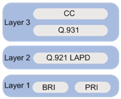
The following describes the functionality of the protocols in the D-channel protocol stack:
· Q.921—Provides the following functions:
¡ A reliable transport for Layer 3 Q.931 signaling messages.
¡ Identification of frames.
¡ Flow control mechanisms for data transmission and reception.
· Q.931—Provides call control and management. These functions include call setup, call disconnection, and request for services from Layer 2.
· Call control (CC)—Forwards messages received by Q.931 from the network side to higher-layer applications such as the DDR or voice module for information conversion and call routing.
Figure 1 ISDN D-channel protocol stack
ISDN application scenarios
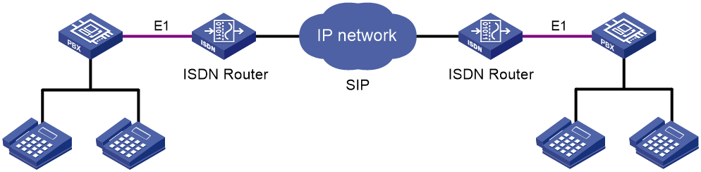
Figure 2 and Figure 3 show typical ISDN network diagrams for data services and voice services, respectively.
Figure 2 Data ISDN application scenario

Figure 3 Voice ISDN application scenario
Prerequisites for ISDN
Before you can use a CE1/PRI or CT1/PRI interface to provide ISDN PRI services, you must use the pri-set command to bundle timeslots into channel sets on the interface. For each PRI set, the system creates a serial interface automatically. To configure ISDN settings for a PRI set, you must enter the view of this serial interface.
This feature is supported only on routers with the BS, E1, or T1 interface modules installed.
Before you can use a CE1/PRI or CT1/PRI interface to provide ISDN PRI services, you must use the pri-set command to bundle timeslots into channel sets on the interface. For each PRI set, the system creates a serial interface automatically. To configure ISDN settings for a PRI set, you must enter the view of this serial interface. For more information about timeslot bundling, see the WAN interface section in Interface Configuration Guide.
The following routers do not support ISDN BRI interfaces:
· MSR3620-X1.
· MSR3620-X1-XS.
· MSR3640-X1.
· MSR3640-XS.
· MSR3640-X1-HI.
· MSR3660-XS.
ISDN tasks at a glance
This chapter describes only ISDN configurations on a BRI or PRI interface. For more information about other BRI and PRI interface configurations, see Interface Configuration Guide.
ISDN BRI interface tasks at a glance
To configure an ISDN BRI interface, perform the following tasks:
1. Setting the ISDN switch type on an ISDN interface
2. Setting the ISDN functionality of an ISDN interface
3. (Optional.) Configuring SPID parameters for the NI switch type
4. Configuring Q.931 negotiation parameters
5. (Optional.) Configuring Q.931 call control parameters
¡ Configuring B-channel selection
¡ Configuring calling number verification for incoming calls
¡ Configuring called-number verification for incoming calls
¡ Configuring ISDN calling number identification
6. (Optional.) Configuring the Q.921 operating parameters
¡ Configuring the data link type of a BRI interface
¡ Configuring per-channel TEI assignment on a BRI interface
¡ Configuring the leased line service for an ISDN BRI interface
¡ Enabling permanent Q.921 link connectivity on an BRI interface
¡ Enabling persistent Layer 1 activation on a BRI interface
¡ Configuring a BRI interface to supply line power
¡ Configuring the sliding window size on an ISDN BRI interface
ISDN PRI interface tasks at a glance
To configure an ISDN PRI interface, perform the following tasks:
1. Setting the ISDN switch type on an ISDN interface
2. Setting the ISDN functionality of an ISDN interface
3. Configuring Q.931 negotiation parameters
4. (Optional.) Configuring Q.931 call control parameters
¡ Configuring B-channel selection
¡ Configuring calling number verification for incoming calls
¡ Configuring called-number verification for incoming calls
¡ Configuring ISDN calling number identification
5. (Optional.) Configuring the sliding window size on an ISDN PRI interface
Setting the ISDN switch type on an ISDN interface
About this task
ISDN service providers in different countries implement variants of ISDN to provide ISDN services, such as NTT, ETSI, NI, AT&T, and ANSI. When you configure an ISDN interface, you must set the switch type on the interface to be the same as the service provider switch type.
The device provides full support for DSS1. For any other variants of ISDN, the device only provides the basic call functionality.
Restrictions and guidelines
Only interfaces on the user side support the ANSI, AT&T, ETSI, NI, and NTT ISDN switch types.
You cannot perform this task when a call is present on the ISDN interface.
Table 3 shows the ISDN switch types available on an ISDN interface.
Table 3 ISDN switch type and ISDN interface compatibility matrix
|
Switch type |
BRI |
CT1/PRI |
CE1/PRI |
|
ANSI |
Yes |
Yes |
No |
|
AT&T |
No |
Yes |
No |
|
5ESS |
No |
Yes |
No |
|
DSS1 |
Yes |
Yes |
Yes |
|
ETSI |
Yes |
Yes |
Yes |
|
NI |
Yes |
No |
No |
|
NI2 |
No |
Yes |
No |
|
QSIG |
No |
Yes |
Yes |
|
NTT |
Yes |
Yes |
No |
Procedure
1. Enter system view.
system-view
2. Enter ISDN BRI or PRI interface view.
interface interface-type interface-number
3. Set the ISDN switch type.
isdn protocol-type protocol
The default is DSS1 for both BRI and PRI.
Setting the ISDN functionality of an ISDN interface
About this task
An ISDN interface can provide the ISDN user-side or network-side functionality. For two ISDN devices to communicate with each other, you must configure one end as the network side and configure the other end as the user side.
Restrictions and guidelines
Typically, an ISDN interface is operating as the user side. However, when a BRI interface on a BSV card is connected directly to an ISDN phone, you must configure the BRI interface as the network side.
You must configure the ISDN interface as the user side in the following situations:
· The BRI interface for data services must operate on the user side.
· ANSI, AT&T, ETSI, NI, or NTT is configured.
You cannot perform this task when a call is present on the ISDN interface.
Procedure
1. Enter system view.
system-view
2. Enter ISDN BRI or PRI interface view.
interface interface-type interface-number
3. Configure the interface as the user side or network side.
isdn protocol-mode { network | user }
The default is user side.
Configuring SPID parameters for the NI switch type
About configuring SPID parameters for the NI switch type
NI service provider switches use service profile identifications (SPIDs) to identify services (audio, data, or speech) subscribed to by ISDN devices.
The service provider assigns one SPID for each B-channel. The device cannot place or receive calls until it sends a valid SPID when it initializes a connection to the service provider switch.
SPIDs can be assigned through static manual configuration or dynamic negotiation. You must configure the SPID assignment as required by the service provider.
An NI-enabled BRI interface sends SPID information in Q.931 INFORMATION messages during SPID negotiation and Layer 3 initialization.
Configuring dynamic SPID negotiation
About this task
By default, the device uses dynamic negotiation to obtain SPIDs.
When dynamic SPID negotiation is used, the service provider switch sends available SPIDs to the device. The device selects the SPID that best suits the current configuration. By default, the device preferentially chooses the SPID that includes both speech and data services.
Restrictions and guidelines
You cannot perform this task when SPID negotiation is present on the ISDN BRI interface.
Procedure
1. Enter system view.
system-view
2. Enter ISDN BRI interface view.
interface bri interface-number
3. Specify a service subscribed to by the device.
isdn spid service [ audio | data | speech ]
By default, the device chooses the SPID that includes both speech and data services.
4. Set the TSPID timer.
isdn spid timer seconds
The default timer value is 30 seconds.
The TSPID timer sets the maximum interval that ISDN waits for a response after it sends an INFORMATION message. The timer starts when the device initiates a SPID negotiation or Layer 3 initialization.
The interface retransmits the INFORMATION message if it has not received a response from the service provider switch before the TSPID timer expires.
5. Set the maximum number of INFORMATION retransmissions.
isdn spid resend times
The default is 1.
6. (Optional.) Initiate a SPID negotiation.
isdn spid auto-trigger
By default, a BRI interface initiates a SPID negotiation when it receives a call request.
Configuring static SPID assignment
About this task
If static SPID assignment is used, you must manually configure the SPIDs assigned by the service provider for each B-channel on the BRI interface. When establishing a call, ISDN sends the manually assigned SPID in the ISDN Layer 3 initialization procedure without prior SPID negotiation.
Restrictions and guidelines
Configure a local dialing number (LDN) depending on the service provider requirement. If an LDN is configured, the setting for the isdn calling command becomes invalid.
You cannot configure SPIDs in one of the following conditions:
· A call is present.
· A SPID negotiation is present.
Procedure
1. Enter system view.
system-view
2. Enter ISDN BRI interface view.
interface bri interface-number
3. Assign a SPID to the B1 channel.
isdn spid1 spid [ ldn ]
By default, no SPID or LDN is configured for the B1 channel on a BRI interface.
4. Assign a SPID to the B2 channel.
isdn spid2 spid [ ldn ]
By default, no SPID or LDN is configured for the B2 channel on a BRI interface.
5. Set the TSPID timer.
isdn spid timer seconds
The default timer value is 30 seconds.
The TSPID timer sets the maximum interval that ISDN waits for a response after it sends an INFORMATION message. The timer starts when the device initiates a SPID negotiation or Layer 3 initialization.
The interface retransmits the INFORMATION message if it has not received a response from the service provider switch before the TSPID timer expires.
6. Set the maximum number of INFORMATION retransmissions.
isdn spid resend times
The default is 1.
Enabling NIT mode for NI-type switches incapable of SPID negotiation
About this task
Typically, the NI-enabled BRI interface must pass SPID negotiation or initiation before it can place a call.
You must enable Not Initial Terminal (NIT) mode on the BRI interface if the NI-type service provider switch does not support SPID negotiation.
Procedure
1. Enter system view.
system-view
2. Enter ISDN BRI interface view.
interface bri interface-number
3. Enable NIT mode.
isdn spid nit
By default, NIT mode is disabled. The BRI interface performs dynamic SPID negotiation.
Configuring Q.931 negotiation parameters
1. Enter system view.
system-view
2. Enter ISDN BRI or PRI interface view.
interface interface-type interface-number
3. Set the length of the call reference value.
isdn crlength call-reference-length
By default, the call reference length is 2 bytes for CE1/PRI and CT1/PRI interfaces and 1 byte for the BRI interface.
4. Configure the CONNECT ACK processing method.
isdn ignore connect-ack [ incoming | outgoing ]
By default:
¡ After sending a CONNECT request, ISDN waits for a CONNECT ACK before it changes to the ACTIVE state for traffic transmission.
¡ After receiving a CONNECT request, ISDN sends a CONNECT ACK and changes to the ACTIVE state.
5. Exclude the compatibility information element from the outgoing SETUP message.
¡ Exclude the high layer compatibility (HLC) information element from the outgoing SETUP message.
isdn ignore hlc
By default, all ISDN protocols except 5ESS and QSIG include the HLC information element in the SETUP message.
The HLC element provides high layer compatibility check information for the called party. The called party will reject the call setup request if it detects an incompatibility.
¡ Exclude the lower layer compatibility (LLC) information element from the outgoing SETUP message.
isdn ignore llc
By default, all ISDN protocols except 5ESS and QSIG include the LLC information element in the SETUP message.
6. Exclude or ignore the sending complete indication for call setup.
isdn ignore sending-complete [ incoming | outgoing ]
By default:
¡ The device checks incoming SETUP messages for the sending complete indication.
¡ The device includes a sending complete indication in outgoing SETUP messages.
7. Set the value of an ISDN L3 timer.
isdn l3-timer timer-name time-interval
The default ISDN L3 timer values vary by ISDN protocol. For the default timer values, use the display isdn parameters command.
8. Set the number type and numbering plan identification for calling numbers or called numbers.
isdn number-property number-property [ calling | called ] [ in | out ]
By default, the system automatically selects a number type and numbering plan appropriate to the upper-layer service.
9. Enable overlap sending for called numbers.
isdn overlap-sending [ digits ]
By default, en-bloc sending is enabled for called numbers. In the SETUP message, ISDN includes all information required by the network to process the call.
10. Configure the fields to be included in outgoing packets.
¡ Include the calling-name field in outgoing packets.
isdn carry calling-name
By default, ISDN does not include the calling-name field in outgoing packets.
¡ Include the connected-name field in outgoing packets.
isdn carry connected-name
By default, ISDN does not include the connected-name field in outgoing packets.
11. Configure the ISDN interface to interpret the PROGRESS message as the ALERTING message.
isdn progress-to-alerting enable
By default, this function is disabled.
12. Set the progress description in the progress indicator information element of ISDN signaling messages.
isdn progress-indicator indicator
By default, ISDN uses the progress description assigned by the upper-layer voice service.
Configuring Q.931 call control parameters
To ensure successful call setup, make sure the call control parameters match the service provider's settings.
Configuring B-channel selection
About this task
Efficient B-channel selection for calls improves call establishment efficiency and reduces call losses on ISDN lines, especially PRI ISDN lines.
By default, ISDN interfaces on the device are operating as the user side, and they do not select B-channels for calls. B-channel selection is done by the service provider switch.
To enable an ISDN interface to select B-channels, you have the following options:
· Use the isdn bch-local-manage command to enable non-exclusive B-channel selection. The interface selects a preferred B-channel for a call, but it will use the B-channel selected by the peer end when a selection conflict occurs.
· Use the isdn bch-local-manage exclusive command to enable exclusive B-channel selection. The interface selects a preferred B-channel for a call, and it does not accept the B-channel selected by the peer end when a selection conflict occurs.
Configure exclusive B-channel selection only when the interface is the network side. If the interface is the user side, exclusive B-channel selection will cause a call establishment failure when a B-channel selection conflict occurs.
Procedure
1. Enter system view.
system-view
2. Enter ISDN BRI or PRI interface view.
interface interface-type interface-number
3. Enable the interface to select B-channels for calls.
isdn bch-local-manage [ exclusive ]
By default, B-channel selection is disabled. The service provider switch selects B-channels for calls.
4. Set a B-channel selection method.
isdn bch-select-way { ascending | descending }
By default, an ISDN interface selects B-channels in ascending order.
This command takes effect only when the isdn bch-local-manage command is configured.
Configuring calling number verification for incoming calls
About this task
Calling number verification enables an ISDN interface to accept calls only from a specific calling party.
Call setup will fail in one of the following conditions:
· The calling number in the incoming SETUP message is not configured on the ISDN interface.
· The incoming SETUP message does not include a calling number.
Procedure
1. Enter system view.
system-view
2. Enter ISDN BRI or PRI interface view.
interface interface-type interface-number
3. Configure an accepted calling number.
isdn caller-number caller-number
By default, an ISDN interface accepts calls from any calling numbers.
Configuring called-number verification for incoming calls
About this task
Called-number verification enables an ISDN interface to accept only calls placed to specific called numbers. You can configure the ISDN interface to verify only the called number or both the called number and the called subaddress. The ISDN interface will accept a call only if the called-number information matches one entry in the list of acceptable called numbers.
Procedure
1. Enter system view.
system-view
2. Enter ISDN BRI or PRI interface view.
interface interface-type interface-number
3. Configure an acceptable called number.
isdn check-called-number check-index called-party-number
By default, ISDN does not check the called number or subaddress in incoming SETUP messages.
Configuring ISDN calling number identification
About this task
ISDN calling number identification enables an ISDN interface to include the call number of a calling party in the outgoing call SETUP messages. The calling number information can be used for various purposes. For example, the service provider can use this information to identify the pricing scheme for the calling party. The called party can use this information to verify the origin of calls.
For the called party to receive the calling number, the connected service provider switch must support transmitting calling numbers.
Restrictions and guidelines
As a best practice, do not configure the calling number to be sent for voice services.
Procedure
1. Enter system view.
system-view
2. Enter ISDN BRI or PRI interface view.
interface interface-type interface-number
3. Specify a calling number.
isdn calling calling-number
By default, ISDN interfaces do not send a calling number in outgoing SETUP messages for any services except voice services.
Configuring the Q.921 operating parameters
Configuring the data link type of a BRI interface
About this task
The data link type of a BRI interface can be one of the following:
· point-to-point—The BRI interface can be connected only to one terminal device.
· point-to-multipoint—The BRI interface can be connected to multiple terminal devices.
Set the data link type of a BRI interface to be the same as its connected service provider switch.
Restrictions and guidelines
If the isdn two-tei command is configured, the data link of the BRI interface must be point-to-multipoint.
You cannot change an ISDN BRI interface's data link type when a call is present.
Procedure
1. Enter system view.
system-view
2. Enter ISDN BRI interface view.
interface bri interface-number
3. Set the data link type.
¡ Set the data link type to point-to-point.
isdn link-mode p2p
¡ Set the data link type to point-to-multipoint.
undo isdn link-mode
The default data link type is point-to-multipoint.
Configuring per-channel TEI assignment on a BRI interface
About this task
Terminal endpoint identifiers (TEIs) are assigned by the service provider to identify terminal devices. A TEI identifies one terminal device on a point-to-point link and identifies more than one terminal device on a point-to-multipoint link.
Typically, service provider switches assign one TEI for both B-channels on a BRI interface. If the service provider switch requires the B-channels to use different TEIs, you must configure the BRI interface to request a TEI from the switch before the interface can establish a call on a B-channel. If per-channel TEI assignment is not configured, only one B-channel can be brought up. For example, you must configure per-channel TEI assignment when a BRI interface is connected to an ISDN NI compliant DMS-100 switch in the North America.
Restrictions and guidelines
You cannot configure per-channel TEI assignment in the following situations:
· The BRI interface's data link type is point-to-point.
· A call is present on the interface.
Procedure
1. Enter system view.
system-view
2. Enter ISDN BRI interface view.
interface bri interface-number
3. Enable per-channel TEI assignment.
isdn two-tei
By default, all B-channels on a BRI interface use the same TEI.
Configuring the leased line service for an ISDN BRI interface
About this task
A BRI interface has two channels, B1 and B2. You can configure either or both of the channels to provide 64-kbps leased line service, or combine the channels to provide 128-kbps leased line service.
Procedure
1. Enter system view.
system-view
2. Enter ISDN BRI interface view.
interface bri interface-number
3. Configure the leased line service for the ISDN BRI interface.
isdn leased-line [ B1 | B2 | 128 ]
By default, no B channel on the ISDN BRI interface is configured for leased line service.
Enabling permanent Q.921 link connectivity on an BRI interface
About this task
When this feature is enabled, the ISDN BRI interface establishes and maintains permanent data link connections automatically, regardless of whether or not a call is present.
When this feature is disabled, the ISDN BRI interface transits to the multiframe established state only when a call is present. In multiframe established state, the interface disconnects the Q.921 link if no Q.931 call is present when the T325 timer expires.
To ensure successful call setup when ISDN NI is used, you must enable permanent Q.921 link connectivity.
Restrictions and guidelines
You can enable permanent Q.921 link connectivity only on user-side ISDN BRI interfaces.
Procedure
1. Enter system view.
system-view
2. Enter ISDN BRI interface view.
interface bri interface-number
3. Enable permanent Q.921 link connectivity.
isdn q921-permanent
By default, permanent Q.921 link connectivity is disabled.
Enabling persistent Layer 1 activation on a BRI interface
About this task
Persistent Layer 1 activation is available only on network-side BRI interfaces.
|
|
NOTE: Only BRI interfaces on the BSV module can operate on the network side. |
For energy efficiency, a network-side ISDN interface typically deactivates the physical layer when the data link layer connection is disconnected. To maintain physical layer connectivity when the data link connection is lost, enable persistent Layer 1 activation. This function prevents Q.921 from sending deactivation requests to the physical layer.
Persistent Layer 1 activation can only maintain the active state of the physical layer. It does not activate the physical layer if you enable it when the physical layer is inactive. In contrast, Q.921 attempts to set up data link connections if you enable permanent Q.921 link connectivity when no data link connections are present.
Procedure
1. Enter system view.
system-view
2. Enter ISDN BRI interface view.
interface bri interface-number
3. Enable persistent Layer 1 activation.
permanent-active
By default, a BRI interface deactivates the physical layer when the Q.921 data link is disconnected.
Configuring a BRI interface to supply line power
About this task
You can configure network-side BRI interfaces to supply line power to the terminal equipment.
|
|
NOTE: Only BRI interfaces on the BSV module can operate on the network side. |
Restrictions and guidelines
You can perform this task only network-side BRI interfaces with no calls present.
Procedure
1. Enter system view.
system-view
2. Enter ISDN BRI interface view.
interface bri interface-number
3. Configure the interface to supply line power.
power-source
By default, remote powering is disabled.
|
|
CAUTION: After you execute the undo power-source command on an ISDN BRI interface, the device (for example, an ISDN digital telephone) whose power is remotely provided by the BRI interface is powered off. |
Configuring the sliding window size on an ISDN BRI interface
About this task
Q.921 sends frames in order of their sequence numbers and requires an acknowledgment of each transmitted frame. To improve transmission efficiency, Q.921 does not wait for a transmitted frame to be acknowledged before it sends the next frame. Instead, it uses a sliding window mechanism for transmission.
The sliding window mechanism enables Q.921 to send multiple continuous frames without waiting for the acknowledgment of the previous frame. The sliding window size sets the maximum number of unacknowledged frames. You can tune the size depending on the link status to maximize the throughput.
When sending a frame, Q.921 checks the number of unacknowledged frames. For example, V(A) is the sequence number of the previous acknowledged frame, V(S) is the sequence number of the frame to be sent, and k is the sliding window size. If V(A) + k = V(S), the system stops sending frames.
Procedure
1. Enter system view.
system-view
2. Enter ISDN BRI interface view.
interface bri interface-number
3. Configure the sliding window size.
isdn bri-slipwnd-size window-size
The default window size is 1.
Configuring the sliding window size on an ISDN PRI interface
About this task
Q.921 sends frames in order of their sequence numbers and requires an acknowledgment of each transmitted frame. To improve transmission efficiency, Q.921 does not wait for a transmitted frame to be acknowledged before it sends the next frame. Instead, it uses a sliding window mechanism for transmission.
The sliding window mechanism enables Q.921 to send multiple continuous frames without waiting for the acknowledgment of the previous frame. The sliding window size sets the maximum number of unacknowledged frames. You can tune the size depending on the link status to maximize the throughput.
When sending a frame, Q.921 checks the number of unacknowledged frames. Suppose V(A) is the sequence number of the previous acknowledged frame, V(S) is the sequence number of the frame to be sent, and k is the sliding window size. If V(A) + k = V(S), the system stops sending frames.
Procedure
1. Enter system view.
system-view
2. Enter ISDN PRI interface view.
interface interface-type interface-number
3. Configure the sliding window size.
isdn pri-slipwnd-size window-size
The default window size is 7.
Display and maintenance commands for ISDN
Execute display commands in any view.
|
Task |
Command |
|
Display information about successful Q.931 calls on ISDN interfaces. |
display isdn active-channel [ interface interface-type interface-number ] |
|
Display information about calls on ISDN interfaces. |
display isdn call-info [ interface interface-type interface-number ] |
|
Display ISDN call history records. |
display isdn call-record [ interface interface-type interface-number ] |
|
Display ISDN Layer 2 and Layer 3 protocol parameters. |
display isdn parameters { protocol | interface interface-type interface-number } |
|
Display SPID information for NI-enabled BRI interfaces. |
display isdn spid [ interface interface-type interface-number ] |
ISDN configuration examples
Example: Configuring ISDN PRI
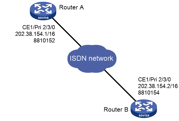
Network configuration
As shown in Figure 4, configure an ISDN PRI line between Router A and Router B for data transmission.
Procedure
In this example, the ISDN PRI interfaces on Router A and Router B are operating as the user side (the default). You must configure the ISDN PRI interfaces as the network side on the service provider switches connected to the routers.
1. Configure Router A:
# Bundle timeslots into a PRI set on CE1/PRI interface E1 2/3/0.
<RouterA> system-view
[RouterA] controller e1 2/3/0
[RouterA-E1 2/3/0] pri-set
[RouterA-E1 2/3/0] quit
# Configure dialer access group 1 to allow any IP packets to trigger a call setup.
[RouterA] dialer-group 1 rule ip permit
# Assign Serial 2/3/0:15 an IP address.
[RouterA] interface serial 2/3/0:15
[RouterA-Serial2/3/0:15] ip address 202.38.154.1 255.255.0.0
# Enable C-DDR on Serial 2/3/0:15, configure the route to Router B, and assign Serial 2/3/0:15 to dialer-group 1.
[RouterA-Serial2/3/0:15] dialer circular enable
[RouterA-Serial2/3/0:15] dialer route ip 202.38.154.2 8810154
[RouterA-Serial2/3/0:15] dialer-group 1
2. Configure Router B:
# Bundle timeslots into a PRI set on CE1/PRI interface E1 2/3/0.
<RouterB> system-view
[RouterB] controller e1 2/3/0
[RouterB-E1 2/3/0] pri-set
[RouterB-E1 2/3/0] quit
# Create dialer access group 1 to allow any IP packets to trigger a call setup.
[RouterB] dialer-group 1 rule ip permit
# Assign Serial 2/3/0:15 an IP address.
[RouterB] interface serial 2/3/0:15
[RouterB-Serial2/3/0:15] ip address 202.38.154.2 255.255.0.0
# Enable C-DDR on Serial 2/3/0:15, configure the route to Router A, and assign Serial 2/3/0:15 to dialer access group 1.
[RouterB-Serial2/3/0:15] dialer circular enable
[RouterB-Serial2/3/0:15] dialer route ip 202.38.154.1 8810152
[RouterB-Serial2/3/0:15] dialer-group 1
Verify the configuration
# Ping 202.38.154.2 from Router A to verify that the state of a B-channel on E1 2/3/0 changes to Line up.
# Ping 202.38.154.2 again to verify that the ISDN PRI line transfers data without any losses.
Example: Configuring NI-enabled ISDN BRI
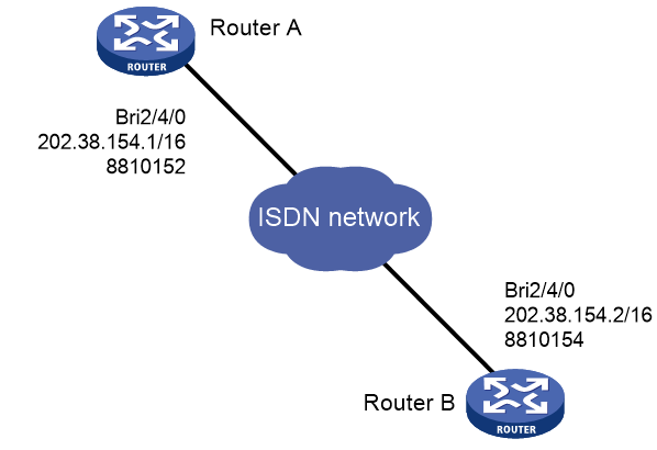
Network configuration
As shown in Figure 5, configure an NI-enabled ISDN BRI line between Router A and Router B for data transmission.
Procedure
In this example, the ISDN BRI interfaces on Router A and Router B are operating on the user side (the default). You must configure the ISDN PRI interfaces as the network side on the service provider switches connected to the routers.
1. Configure Router A:
# Configure dialer-group 1 to allow any IP packets to trigger a call setup.
<RouterA> system-view
[RouterA] dialer-group 1 rule ip permit
# Assign an IP address to BRI 2/4/0.
[RouterA] interface bri 2/4/0
[RouterA-Bri2/4/0] ip address 202.38.154.1 255.255.0.0
# Enable C-DDR on BRI 2/4/0, configure the route to Router B, and assign BRI 2/4/0 to dialer-group 1.
[RouterA-Bri2/4/0] dialer circular enable
[RouterA-Bri2/4/0] dialer route ip 202.38.154.2 8810154
[RouterA-Bri2/4/0] dialer-group 1
# Set the switch type to NI on BRI 2/4/0.
[RouterA-Bri2/4/0] isdn protocol-type ni
# On BRI 2/4/0, assign SPID 54321 to the B1 channel and SPID 65432 to the B2 channel.
[RouterA-Bri2/4/0] isdn spid1 54321
[RouterA-Bri2/4/0] isdn spid2 65432
# On BRI 2/4/0, set the maximum number of INFORMATION retransmissions to 2.
[RouterA-Bri2/4/0] isdn spid resend 2
2. Configure Router B:
# Configure dialer-group 1 to allow any IP packets to trigger a call setup.
<RouterB> system-view
[RouterB] dialer-group 1 rule ip permit
# Assign an IP address to BRI 2/4/0.
[RouterB] interface bri 2/4/0
[RouterB-Bri2/4/0] ip address 202.38.154.2 255.255.0.0
# Enable C-DDR on BRI 2/4/0, configure the route to Router A, and assign BRI 2/4/0 to dialer-group 1.
[RouterB-Bri2/4/0] dialer circular enable
[RouterB-Bri2/4/0] dialer route ip 202.38.154.1 8810152
[RouterB-Bri2/4/0] dialer-group 1
# Set the switch type to NI on BRI 2/4/0.
[RouterB-Bri2/4/0] isdn protocol-type ni
# On BRI 2/4/0, assign SPID 12345 to the B1 channel and SPID 23456 to the B2 channel.
[RouterB-Bri2/4/0] isdn spid1 12345
[RouterB-Bri2/4/0] isdn spid2 23456
# On BRI 2/4/0, set the maximum number of INFORMATION retransmissions to 2.
[RouterB-Bri2/4/0] isdn spid resend 2
Verify the configuration
# Ping 202.38.154.2 from Router A to verify that the state of a B-channel on BRI 2/4/0 changes to Line up.
# Ping 202.38.154.2 again to verify that the ISDN BRI line transfers data without any losses.
Troubleshooting
Symptom
Two devices cannot ping each other over an ISDN PRI or BRI line.
Analysis
The following are typical ISDN call failure causes:
· The ISDN interface is not configured or activated.
· The dial-up configuration is incorrect.
· The line is not well connected.
Solution
To resolve the problem:
1. Execute the display isdn call-info command to verify the interface settings:
a. If the command displays nothing, configure an ISDN interface. For more information about configuring BRI, CE1/PRI, and CT1/PRI interfaces, see Interface Configuration Guide.
b. Verify the Q.921 state of the PRI or BRI interface:
- If the PRI interface's link layer 1 is not in ISDN MULTIPLE_FRAME_ESTABLISHED state, Q.921 negotiation has failed. You must check Q.921 settings or the physical connection.
- If any link layers of the BRI interface are not in TE1_ASSIGNED state, Q.921 negotiation has failed. You must check Q.921 settings or the physical connection.
- If the Q.921 state is correct, verify the dialup configuration.
2. Verify that the physical layer is active:
a. Enable Q.921 debugging.
b. If the system displays a "Failed to send" message, execute the shutdown and undo shutdown command to re-enable the interface.
3. Verify that the dial-up configuration is correct.
4. Verify that the ISDN cables are securely connected.
