- Table of Contents
- Related Documents
-
| Title | Size | Download |
|---|---|---|
| 01-PPP configuration | 768.51 KB |
Contents
PPP link establishment process
Restrictions: Hardware compatibility with PPP
Enabling PPP encapsulation on an interface
Restoring the default settings for the VT interface
Configuring PPP authentication
Configuring PAP authentication
Configuring CHAP authentication (authenticator name is configured)
Configuring CHAP authentication (authenticator name is not configured)
Configuring MS-CHAP or MS-CHAP-V2 authentication
Configuring the polling feature
Configuring the PPP negotiation timeout time
Configuring IP address negotiation on the client
Configuring IP address negotiation on the server
Configuring DNS server IP address negotiation on the client
Configuring DNS server IP address negotiation on the server
Enabling IP header compression
Enabling PPP link quality monitoring
Configuring the NAS-Port-Type attribute
Display and maintenance commands for PPP
Example: Configuring one-way PAP authentication
Example: Configuring two-way PAP authentication
Example: Configuring one-way CHAP authentication
Example: Specifying an IP address for the client on the server interface
Example: Specifying a PPP address pool on the server interface
Example: Using the PPP address pool associated with an ISP domain
Restrictions and guidelines for MP
Hardware and feature compatibility
Configuring MP by using a VT interface
Restrictions and guidelines for MP configuration by using a VT interface
Associating a physical interface or a username with the VT interface
Configuring MP through an MP-group interface
Creating an MP-group interface
Assigning a physical interface to the MP-group interface
Restoring the default settings for the MP-group interface
Configuring short sequence number header format negotiation
Configuring the MP endpoint descriptor
Display and maintenance commands for MP
Example: Binding the physical interfaces to a VT interface
Example: Associating remote usernames with a VT interface
Example: Configuring an MP-group interface
Restrictions: Hardware compatibility with PPPoE
Restrictions and guidelines for PPPoE
PPPoE server tasks at a glance
Enabling the function of querying and configuring VA interfaces through MIB nodes
Setting the maximum number of PPPoE sessions
Limiting the PPPoE access rate
Configuring the NAS-Port-ID attribute
PPPoE client tasks at a glance
Configuring a dialer interface
Display and maintenance commands for PPPoE
Display and maintenance commands for PPPoE server
Display and maintenance commands for PPPoE client
Example: Configuring the PPPoE server to assign IPv4 addresses through a PPP address pool
Example: Configuring the PPPoE server to assign IPv4 addresses through the local DHCP server
Example: Configuring the PPPoE server to assign IPv4 addresses through a remote DHCP server
Example: Configuring the PPPoE server to assign IPv6 addresses through ND and IPv6CP negotiation
Example: Configuring the PPPoE server to assign IPv6 addresses through DHCPv6
Example: Configuring the PPPoE server to assign IPv6 addresses through prefix delegation by DHCPv6
Example: Configuring PPPoE server to assign address pools and VPNs
Example: Configuring a PPPoE client in permanent mode
Example: Configuring a PPPoE client in on-demand mode
Example: Configuring a PPPoE client in diagnostic mode
Example: Connecting a LAN to the Internet through an ADSL modem
Configuring PPP
About PPP
Point-to-Point Protocol (PPP) is a point-to-point link layer protocol. It provides user authentication, supports synchronous/asynchronous communication, and allows for easy extension.
PPP protocols
PPP includes the following protocols:
· Link control protocol (LCP)—Establishes, tears down, and monitors data links.
· Network control protocol (NCP)—Negotiates the packet format and type for data links.
· Authentication protocols—Authenticate users. Protocols include the following:
¡ Password Authentication Protocol (PAP).
¡ Challenge Handshake Authentication Protocol (CHAP).
¡ Microsoft CHAP (MS-CHAP).
¡ Microsoft CHAP Version 2 (MS-CHAP-V2).
PPP link establishment process
Figure 1 shows the PPP link establishment process.
Figure 1 PPP link establishment process
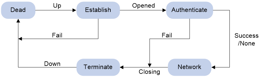
1. Initially, PPP is in Link Dead phase. After the physical layer goes up, PPP enters the Link Establishment phase (Establish).
2. In the Link Establishment phase, the LCP negotiation is performed. The LCP configuration options include Authentication-Protocol, Async-Control-Character-Map (ACCM), Maximum-Receive-Unit (MRU), Magic-Number, Protocol-Field-Compression (PFC), Address-and-Control-Field-Compression (ACFC), and MP.
¡ If the negotiation fails, LCP reports a Fail event, and PPP returns to the Dead phase.
¡ If the negotiation succeeds, LCP enters the Opened state and reports an Up event, indicating that the underlying layer link has been established. At this time, the PPP link is not established for the network layer, and network layer packets cannot be transmitted over the link.
3. If authentication is configured, the PPP link enters the Authentication phase, where PAP, CHAP, MS-CHAP, or MS-CHAP-V2 authentication is performed.
¡ If the client fails to pass the authentication, LCP reports a Fail event and enters the Link Termination phase. In this phase, the link is torn down and LCP goes down.
¡ If the client passes the authentication, LCP reports a Success event.
4. If a network layer protocol is configured, the PPP link enters the Network-Layer Protocol phase for NCP negotiation, such as IPCP negotiation and IPv6CP negotiation.
¡ If the NCP negotiation succeeds, the link goes up and becomes ready to carry negotiated network-layer protocol packets.
¡ If the NCP negotiation fails, NCP reports a Down event and enters the Link Termination phase.
If the interface is configured with an IP address, the IPCP negotiation is performed. IPCP configuration options include IP addresses and DNS server IP addresses. After the IPCP negotiation succeeds, the link can carry IP packets.
5. After the NCP negotiation is performed, the PPP link remains active until either of the following events occurs:
¡ Explicit LCP or NCP frames close the link.
¡ Some external events take place (for example, the intervention of a user).
PPP authentication
PPP supports the following authentication methods:
PAP
PAP is a two-way handshake authentication protocol using the username and password.
PAP sends username/password pairs in plain text over the network. If authentication packets are intercepted in transit, network security might be threatened. For this reason, it is suitable only for low-security environments.
CHAP
CHAP is a three-way handshake authentication protocol.
CHAP transmits usernames but not passwords over the network. It transmits the result calculated from the password and random packet ID by using the MD5 algorithm. It is more secure than PAP. The authenticator may or may not be configured with a username. As a best practice, configure a username for the authenticator, which makes it easier for the peer to verify the identity of the authenticator.
MS-CHAP
MS-CHAP is a three-way handshake authentication protocol. MS-CHAP differs from CHAP as follows:
· MS-CHAP uses CHAP Algorithm 0x80.
· MS-CHAP provides authentication retry. If the peer fails authentication, it is allowed to retransmit authentication information to the authenticator for reauthentication. The authenticator allows a peer to retransmit a maximum of three times.
MS-CHAP-V2
MS-CHAP-V2 is a three-way handshake authentication protocol. MS-CHAP-V2 differs from CHAP as follows:
· MS-CHAP-V2 uses CHAP Algorithm 0x81.
· MS-CHAP-V2 provides two-way authentication by piggybacking a peer challenge on the Response packet and an authenticator response on the Acknowledge packet.
· MS-CHAP-V2 supports authentication retry. If the peer fails authentication, it is allowed to retransmit authentication information to the authenticator for reauthentication. The authenticator allows a peer to retransmit a maximum of three times.
· MS-CHAP-V2 supports password change. If the peer fails authentication because of an expired password, it will send the new password entered by the user to the authenticator for reauthentication.
PPP for IPv4
On IPv4 networks, PPP negotiates the IP address and DNS server address during IPCP negotiation.
IP address negotiation
IP address negotiation enables one end to assign an IP address to the other.
An interface can act as a client or a server during IP address negotiation:
· Client—Obtains an IP address from the server. Use the client mode when the device accesses the Internet through an ISP.
· Server—Assigns an IP address to the client. Before you configure the IP address of the server, you must perform one of the following tasks:
¡ Configure a local address pool and associate the pool with the ISP domain.
¡ Specify an IP address or an address pool for the client on the interface.
When IP address negotiation is enabled on a client, the server selects an IP address for the client in the following sequence:
1. If the AAA server configures an IP address or address pool for the client, the server selects that IP address or an IP address from the pool. The IP address or address pool is configured on the AAA server instead of the PPP server. For information about AAA, see Security Configuration Guide.
2. If an address pool is associated with the ISP domain used during client authentication, the server selects an IP address from the pool.
3. If an IP address or address pool is specified for the client on the interface of the server, the server selects that IP address or an IP address from that pool.
DNS server address negotiation
IPCP negotiation can determine the DNS server IP address.
When the device is connected to a host, configure the device as the server to assign the DNS server IP address to the host.
When the device is connected to an ISP access server, configure the device as the client. Then, the device can obtain the DNS server IP address from the ISP access server.
PPP for IPv6
On IPv6 networks, PPP negotiates only the IPv6 interface identifier instead of the IPv6 address and IPv6 DNS server address during IPv6CP negotiation.
IPv6 address assignment
PPP cannot negotiate the IPv6 address.
The client can get an IPv6 global unicast address through the following methods:
· Method 1—The client obtains an IPv6 prefix in an RA message. The client then generates an IPv6 global unicast address by combining the IPv6 prefix and the negotiated IPv6 interface identifier. The IPv6 prefix in the RA message is determined in the following sequence:
¡ IPv6 prefix authorized by AAA.
¡ RA prefix configured on the interface.
¡ Prefix of the IPv6 global unicast address configured on the interface.
For information about the ND protocol, see Layer 3—IP Services Configuration Guide.
· Method 2—The client requests an IPv6 global unicast address through DHCPv6. The server assigns an IPv6 address to the client from the address pool authorized by AAA. If no AAA-authorized address pool exists, DHCPv6 uses the address pool that matches the server's IPv6 address to assign an IPv6 address to the client. For information about DHCPv6, see Layer 3—IP Services Configuration Guide.
· Method 3—The client requests prefixes through DHCPv6 and assigns them to downstream hosts. The hosts then uses the prefixes to generate global IPv6 addresses. This method uses the same principle of selecting address pools as method 2.
The device can assign a host an IPv6 address in either of the following ways:
· When the host connects to the device directly or through a bridge device, the device can use method 1 or method 2.
· When the host accesses the device through a router, the device can use method 3 to assign an IPv6 prefix to the router. The router assigns the prefix to the host to generate an IPv6 global unicast address.
IPv6 DNS server address assignment
On IPv6 networks, two methods are available for the IPv6 DNS address assignment:
· AAA authorizes the IPv6 DNS address and assigns this address to the host through RA messages.
· The DHCPv6 client requests an IPv6 DNS address from the DHCPv6 server.
Protocols and standards
RFC 1661: The Point-to-Point Protocol (PPP)
Restrictions: Hardware compatibility with PPP
This feature is supported only on routers with the following modules installed:
· AM.
· AS.
· ASE.
· BS.
· CE3.
· CPOS.
· CT3.
· E1.
· E1-F.
· POS.
· SAE.
· T1.
· T1-F.
Support for this feature varies by device model. For more information, see the PPP command reference.
The following matrixes show support of hardware platforms for PPP.
|
Hardware |
PPP compatibility |
|
MSR810, MSR810-W, MSR810-W-DB, MSR810-LM, MSR810-W-LM, MSR810-10-PoE, MSR810-LM-HK, MSR810-W-LM-HK, MSR810-LM-CNDE-SJK, MSR810-CNDE-SJK |
Yes |
|
MSR810-LMS, MSR810-LUS |
No |
|
MSR810-LMS-EA, MSR810-LME |
Yes |
|
MSR1004S-5G |
Yes |
|
MSR2600-6-X1, MSR2600-10-X1, MSR2600-15-X1 |
Yes |
|
MSR 2630 |
Yes |
|
MSR3600-28, MSR3600-51 |
Yes |
|
MSR3600-28-SI, MSR3600-51-SI |
Yes |
|
MSR3600-28-X1, MSR3600-28-X1-DP, MSR3600-51-X1, MSR3600-51-X1-DP |
Yes |
|
MSR3610-I-DP, MSR3610-IE-DP, MSR3610-IE-ES, MSR3610-IE-EAD, MSR-EAD-AK770, MSR3610-I-IG, MSR3610-IE-IG |
Yes |
|
MSR3610-X1, MSR3610-X1-DP, MSR3610-X1-DC, MSR3610-X1-DP-DC, MSR3620-X1, MSR3640-X1 |
Yes |
|
MSR 3610, MSR 3620, MSR 3620-DP, MSR 3640, MSR 3660 |
Yes |
|
MSR3610-G, MSR3620-G |
Yes |
|
MSR3640-X1-HI |
Yes |
|
Hardware |
PPP compatibility |
|
MSR810-W-WiNet, MSR810-LM-WiNet |
Yes |
|
MSR830-4LM-WiNet |
Yes |
|
MSR830-5BEI-WiNet, MSR830-6EI-WiNet, MSR830-10BEI-WiNet |
Yes |
|
MSR830-6BHI-WiNet, MSR830-10BHI-WiNet |
Yes |
|
MSR2600-6-WiNet, MSR2600-10-X1-WiNet |
Yes |
|
MSR2630-WiNet |
Yes |
|
MSR3600-28-WiNet |
Yes |
|
MSR3610-X1-WiNet |
Yes |
|
MSR3610-WiNet, MSR3620-10-WiNet, MSR3620-DP-WiNet, MSR3620-WiNet, MSR3660-WiNet |
Yes |
|
Hardware |
PPP compatibility |
|
MSR2630-XS |
Yes |
|
MSR3600-28-XS |
Yes |
|
MSR3610-XS |
Yes |
|
MSR3620-XS |
Yes |
|
MSR3610-I-XS |
Yes |
|
MSR3610-IE-XS |
Yes |
|
MSR3620-X1-XS |
Yes |
|
MSR3640-XS |
Yes |
|
MSR3660-XS |
Yes |
|
Hardware |
PPP compatibility |
|
MSR810-LM-GL |
Yes |
|
MSR810-W-LM-GL |
Yes |
|
MSR830-6EI-GL |
Yes |
|
MSR830-10EI-GL |
Yes |
|
MSR830-6HI-GL |
Yes |
|
MSR830-10HI-GL |
Yes |
|
MSR1004S-5G-GL |
Yes |
|
MSR2600-6-X1-GL |
Yes |
|
MSR3600-28-SI-GL |
Yes |
PPP tasks at a glance
To configure PPP, perform the following tasks:
1. Enabling PPP encapsulation on an interface
Perform this task in PPPoE, L2TP, and MP networks.
¡ (Optional.) Restoring the default settings for the VT interface
3. Configuring PPP authentication
Choose one of the following tasks:
¡ Configuring PAP authentication
¡ Configuring CHAP authentication (authenticator name is configured)
¡ Configuring CHAP authentication (authenticator name is not configured)
¡ Configuring MS-CHAP or MS-CHAP-V2 authentication
Configure PPP authentication for high-security environments.
4. (Optional.) Configuring the polling feature
5. (Optional.) Configuring PPP negotiation
¡ Configuring the PPP negotiation timeout time
¡ Configuring IP address negotiation on the client
¡ Configuring IP address negotiation on the server
¡ Configuring DNS server IP address negotiation on the client
¡ Configuring DNS server IP address negotiation on the server
¡ Configuring ACCM negotiation
¡ Configuring ACFC negotiation
6. (Optional.) Enabling IP header compression
IPHC is often used for voice communications over low-speed links.
7. (Optional.) Enabling PPP link quality monitoring
8. (Optional.) Configuring the NAS-Port-Type attribute
9. (Optional.) Enabling PPP accounting
10. (Optional.) Enabling PPP user logging
Enabling PPP encapsulation on an interface
1. Enter system view.
system-view
2. Enter interface view.
interface interface-type interface-number
3. Enable PPP encapsulation on the interface.
link-protocol ppp
By default, all interfaces except Ethernet interfaces, VLAN interfaces, and ATM interfaces use PPP as the link layer protocol.
Configuring a VT interface
Creating a VT interface
About this task
A virtual-template (VT) interface is a template for creating VA interfaces. In PPPoE, L2TP, and MP networks, VA interfaces are needed for exchanging data with peers. In this case, the system will select a VT interface and dynamically create VA interfaces based on the VT interface.
In PPPoE and L2TP applications, you can use VT interfaces to implement related functions of PPP. For more information about PPPoE and L2TP, see "Configuring PPPoE" and "Configuring L2TP."
MP can create multiple bundles using the same VT interface. For more information about MP, see "Configuring MP."
Procedure
1. Enter system view.
system-view
2. Create a VT interface and enter its view.
interface virtual-template number
3. (Optional.) Set the interface description.
description text
By default, the description of a VT interface is interface name Interface, for example, Virtual-Template1 Interface.
4. (Optional.) Set the MTU size of the interface.
mtu size
By default, the MTU size of an interface is 1500 bytes.
5. (Optional.) Set the expected bandwidth of the VT interface.
bandwidth bandwidth-value
By default, the expected bandwidth (in kbps) is the interface baud rate divided by 1000.
Restoring the default settings for the VT interface
Restrictions and guidelines
The default command might interrupt ongoing network services. Make sure you are fully aware of the impact of this command when you execute it on a live network.
The default command might fail to restore the default settings for some commands for reasons such as command dependencies or system restrictions. Use the display this command in interface view to identify these commands. Use the undo forms of these commands or follow the command reference to individually restore their default settings. If your restoration attempt still fails, follow the error message instructions to resolve the problem.
Procedure
1. Enter system view.
system-view
2. Enter VT interface view.
interface virtual-template number
3. Restore the default settings for the interface.
default
Configuring PPP authentication
About PPP authentication
PPP supports authentication methods PAP, CHAP, MS-CHAP, and MS-CHAP-V2. You can configure several authentication modes simultaneously. In LCP negotiation, the authenticator negotiates with the peer in the sequence of configured authentication modes until the LCP negotiation succeeds. If the response packet from the peer carries a recommended authentication mode, the authenticator directly uses the authentication mode if it finds the mode configured.
Configuring PAP authentication
Restrictions and guidelines for PAP authentication
For local AAA authentication, the username and password of the peer must be configured on the authenticator.
For remote AAA authentication, the username and password of the peer must be configured on the remote AAA server.
The username and password configured for the peer must be the same as those configured on the peer by using the ppp pap local-user command.
Configuring the authenticator
1. Enter system view.
system-view
2. Enter interface view.
interface interface-type interface-number
3. Configure the authenticator to authenticate the peer by using PAP.
ppp authentication-mode pap [ [ call-in ] domain { isp-name | default enable isp-name } ]
By default, PPP authentication is disabled.
4. Configure local or remote AAA authentication.
For more information about AAA authentication, see Security Configuration Guide.
Configuring the peer
1. Enter system view.
system-view
2. Enter interface view.
interface interface-type interface-number
3. Configure the PAP username and password sent from the peer to the authenticator when the peer is authenticated by the authenticator by using PAP.
ppp pap local-user username password { cipher | simple } string
By default, when being authenticated by the authenticator by using PAP, the peer sends null username and password to the authenticator.
For security purposes, the password specified in plaintext form and ciphertext form will be stored in encrypted form.
Configuring CHAP authentication (authenticator name is configured)
Restrictions and guidelines for CHAP authentication (authenticator name is configured)
When you configure the authenticator, follow these guidelines:
· For local AAA authentication, the username and password of the peer must be configured on the authenticator.
· For remote AAA authentication, the username and password of the peer must be configured on the remote AAA server.
· The username and password configured for the peer must meet the following requirements:
¡ The username configured for the peer must be the same as that configured on the peer by using the ppp chap user command.
¡ The passwords configured for the authenticator and peer must be the same.
When you configure the peer, follow these guidelines:
· For local AAA authentication, the username and password of the authenticator must be configured on the peer.
· For remote AAA authentication, the username and password of the authenticator must be configured on the remote AAA server.
· The username and password configured for the authenticator must meet the following requirements:
¡ The username configured for the authenticator must be the same as that configured on the authenticator by using the ppp chap user command.
¡ The passwords configured for the authenticator and peer must be the same.
· The peer does not support the CHAP authentication password configured by using the ppp chap password command. CHAP authentication (authenticator name is configured) will apply even if the authentication name is configured.
Configuring the authenticator
1. Enter system view.
system-view
2. Enter interface view.
interface interface-type interface-number
3. Configure the authenticator to authenticate the peer by using CHAP.
ppp authentication-mode chap [ [ call-in ] domain { isp-name | default enable isp-name } ]
By default, PPP authentication is disabled.
4. Configure a username for the CHAP authenticator.
ppp chap user username
The default setting is null.
5. Configure local or remote AAA authentication.
For more information about AAA authentication, see Security Configuration Guide.
Configuring the peer
1. Enter system view.
system-view
2. Enter interface view.
interface interface-type interface-number
3. Configure a username for the CHAP peer.
ppp chap user username
The default setting is null.
4. Configure local or remote AAA authentication.
For more information about AAA authentication, see Security Configuration Guide.
Configuring CHAP authentication (authenticator name is not configured)
Restrictions and guidelines for CHAP authentication (authenticator name is not configured)
For local AAA authentication, the username and password of the peer must be configured on the authenticator.
For remote AAA authentication, the username and password of the peer must be configured on the remote AAA server.
The username and password configured for the peer must meet the following requirements:
· The username configured for the peer must be the same as that configured on the peer by using the ppp chap user command.
· The password configured for the peer must be the same as that configured on the peer by using the ppp chap password command.
Configuring the authenticator
1. Enter system view.
system-view
2. Enter interface view.
interface interface-type interface-number
3. Configure the authenticator to authenticate the peer by using CHAP.
ppp authentication-mode chap [ [ call-in ] domain { isp-name | default enable isp-name } ]
By default, PPP authentication is disabled.
4. Configure local or remote AAA authentication.
For more information about AAA authentication, see Security Configuration Guide.
Configuring the peer
1. Enter system view.
system-view
2. Enter interface view.
interface interface-type interface-number
3. Configure a username for the CHAP peer.
ppp chap user username
The default setting is null.
4. Set the CHAP authentication password.
ppp chap password { cipher | simple } string
The default setting is null.
For security purposes, the password specified in plaintext form and ciphertext form will be stored in encrypted form.
Configuring MS-CHAP or MS-CHAP-V2 authentication
Restrictions and guidelines for MS-CHAP or MS-CHAP-V2 authentication
The device can only act as an authenticator for MS-CHAP or MS-CHAP-V2 authentication.
L2TP supports only MS-CHAP authentication.
MS-CHAP-V2 authentication supports password change only when using RADIUS.
As a best practice, do not set the authentication method for PPP users to none when MS-CHAP-V2 authentication is used.
For local AAA authentication, the username and password of the peer must be configured on the authenticator. For remote AAA authentication, the username and password of the peer must be configured on the remote AAA server. The username and password of the peer configured on the authenticator or remote AAA server must be the same as those configured on the peer.
If authentication name is configured, the username configured for the authenticator on the peer must be the same as that configured on the authenticator by using the ppp chap user command.
Configuring MS-CHAP or MS-CHAP-V2 authentication (authenticator name is configured)
1. Enter system view.
system-view
2. Enter interface view.
interface interface-type interface-number
3. Configure the authenticator to authenticate the peer by using MS-CHAP or MS-CHAP-V2.
ppp authentication-mode { ms-chap | ms-chap-v2 } [ [ call-in ] domain { isp-name | default enable isp-name } ]
By default, PPP authentication is disabled.
4. Configure a username for the MS-CHAP or MS-CHAP-V2 authenticator.
ppp chap user username
5. Configure local or remote AAA authentication.
For more information about AAA authentication, see Security Configuration Guide.
Configuring MS-CHAP or MS-CHAP-V2 authentication (authenticator name is not configured)
1. Enter system view.
system-view
2. Enter interface view.
interface interface-type interface-number
3. Configure the authenticator to authenticate the peer by using MS-CHAP or MS-CHAP-V2.
ppp authentication-mode { ms-chap | ms-chap-v2 } [ [ call-in ] domain { isp-name | default enable isp-name } ]
By default, PPP authentication is disabled.
4. Configure local or remote AAA authentication.
For more information about AAA authentication, see Security Configuration Guide.
Configuring the polling feature
About this task
The polling feature checks PPP link state.
On an interface that uses PPP encapsulation, the link layer sends keepalive packets at keepalive intervals to detect the availability of the peer. If the interface receives no response to keepalive packets when the keepalive retry limit is reached, it determines that the link fails and reports a link layer down event.
To set the keepalive retry limit, use the timer-hold retry command.
The value 0 disables an interface from sending keepalive packets. In this case, the interface can respond to keepalive packets from the peer.
Restrictions and guidelines
On a slow link, increase the keepalive interval to prevent false shutdown of the interface. This situation might occur when keepalive packets are delayed because a large packet is being transmitted on the link.
In an MP bundle, only channels support the polling feature, and the MP bundle does not support polling. Even if you configure polling on an MP bundle, polling does take effect on the MP bundle.
Procedure
1. Enter system view.
system-view
2. Enter interface view.
interface interface-type interface-number
3. Set the keepalive interval.
timer-hold seconds
The default setting is 10 seconds.
4. Set the keepalive retry limit.
timer-hold retry retries
The default setting is 5.
Configuring PPP negotiation
Configuring the PPP negotiation timeout time
About this task
The device starts the PPP negotiation timeout timer after sending a packet. If no response is received before the timer expires, the device sends the packet again.
If two ends of a PPP link vary greatly in the LCP negotiation packet processing rate, configure this command on the end with a higher processing rate. The LCP negotiation delay timer prevents frequent LCP negotiation packet retransmission. After the physical layer comes up, PPP starts LCP negotiation when the delay timer expires. If PPP receives LCP negotiation packets before the delay timer expires, it starts LCP negotiation immediately.
Procedure
1. Enter system view.
system-view
2. Enter interface view.
interface interface-type interface-number
3. Configure the negotiation timeout time.
ppp timer negotiate seconds
The default setting is 3 seconds.
4. (Optional.) Set the LCP negotiation delay timer.
ppp lcp delay milliseconds
By default, PPP starts LCP negotiation immediately after the physical layer comes up.
Configuring IP address negotiation on the client
1. Enter system view.
system-view
2. Enter interface view.
interface interface-type interface-number
3. Enable IP address negotiation.
ip address ppp-negotiate
By default, IP address negotiation is not enabled.
If you execute this command and the ip address command multiple times, the most recent configuration takes effect. For more information about the ip address command, see Layer 3—IP Services Command Reference.
Configuring IP address negotiation on the server
About this task
Configure the server to assign an IP address to a client by using the following methods:
· Method 1: Specify an IP address for the client on the server interface.
· Method 2: Specify a PPP or DHCP address pool on the server interface.
· Method 3: Associate a PPP or DHCP address pool with an ISP domain.
Restrictions and guidelines for IP address negotiation on the server
For clients requiring no authentication, you can use either method 1 or method 2. When both method 1 and method 2 are configured, the most recent configuration takes effect.
For clients requiring authentication, you can use one or more of the three methods. When multiple methods are configured, method 3 takes precedence over method 1 or method 2. When both method 1 and method 2 are configured, the most recent configuration takes effect.
PPP supports IP address assignment from a PPP or DHCP address pool. If you use a pool name that identifies both a PPP address pool and a DHCP address pool, the system uses the PPP address pool.
When assigning IP address to users through a PPP address pool, make sure the PPP address pool excludes the gateway IP address of the PPP address pool.
Specifying an IP address for the client on the server interface
1. Enter system view.
system-view
2. Enter interface view.
interface interface-type interface-number
3. Configure the interface to assign an IP address to the peer.
remote address ip-address
By default, an interface does not assign an IP address to the peer.
4. Configure an IP address for the interface.
ip address ip-address
By default, no IP address is configured on an interface.
Specifying a PPP address pool on the server interface
1. Enter system view.
system-view
2. Configure a PPP address pool.
ip pool pool-name start-ip-address [ end-ip-address ] [ group group-name ]
3. (Optional.) Configure a gateway address for the PPP address pool.
ip pool pool-name gateway ip-address [ vpn-instance vpn-instance-name ]
By default, the PPP address pool is not configured with a gateway address.
4. (Optional.) Configure a PPP address pool route.
ppp ip-pool route ip-address { mask-length | mask } [ vpn-instance vpn-instance-name ]
By default, no PPP address pool route exists.
The destination network of the PPP address pool route must include the PPP address pool.
5. Enter interface view.
interface interface-type interface-number
6. Configure the interface to assign an IP address from the configured PPP address pool to the peer.
remote address pool pool-name
By default, an interface does not assign an IP address to the peer.
7. Configure an IP address for the interface.
ip address ip-address
By default, no IP address is configured on an interface.
Specifying a DHCP address pool on the server interface
1. Enter system view.
system-view
2. Configure DHCP.
¡ If the server acts as a DHCP server, perform the following tasks:
- Configure the DHCP server.
- Configure a DHCP address pool on the server.
¡ If the server acts as a DHCP relay agent, perform the following tasks:
- Configure the DHCP relay agent on the server.
- Configure a DHCP address pool on the remote DHCP server.
- Enable the DHCP relay agent to record relay entries.
- Configure a DHCP relay address pool.
For information about configuring a DHCP server and a DHCP relay agent, see Layer 3—IP Services Configuration Guide.
3. Enter interface view.
interface interface-type interface-number
4. Configure the interface to assign an IP address from the configured DHCP address pool to the peer.
remote address pool pool-name
By default, an interface does not assign an IP address to the peer.
5. (Optional.) Configure the DHCP client IDs for PPP users acting as DHCP clients.
remote address dhcp client-identifier { callingnum | username }
By default, no DHCP client IDs are configured for PPP users acting as DHCP clients.
When PPP usernames are used as DHCP client IDs, make sure different users use different PPP usernames to come online.
6. Configure an IP address for the interface.
ip address ip-address
By default, no IP address is configured on an interface.
Associating a PPP address pool with an ISP domain
1. Enter system view.
system-view
2. Configure a PPP address pool.
ip pool pool-name start-ip-address [ end-ip-address ] [ group group-name ]
By default, no PPP address pool is configured.
3. (Optional.) Configure a gateway address for the PPP address pool.
ip pool pool-name gateway ip-address [ vpn-instance vpn-instance-name ]
By default, the PPP address pool is not configured with a gateway address.
4. (Optional.) Configure a PPP address pool route.
ppp ip-pool route ip-address { mask-length | mask } [ vpn-instance vpn-instance-name ]
By default, no PPP address pool route exists.
The destination network of the PPP address pool route must include the PPP address pool.
5. Enter ISP domain view.
domain isp-name
6. Associate the ISP domain with the configured PPP address pool for address assignment.
authorization-attribute ip-pool pool-name
By default, no PPP address pool is associated.
For more information about this command, see Security Command Reference.
7. Return to system view.
quit
8. Enter interface view.
interface interface-type interface-number
9. Configure an IP address for the interface.
ip address ip-address
By default, no IP address is configured on an interface.
Associating a DHCP address pool with an ISP domain
1. Enter system view.
system-view
2. Configure DHCP.
¡ If the server acts as a DHCP server, perform the following tasks:
- Configure the DHCP server.
- Configure a DHCP address pool on the server.
¡ If the server acts as a DHCP relay agent, perform the following tasks:
- Configure the DHCP relay agent on the server.
- Configure a DHCP address pool on the remote DHCP server.
- Enable the DHCP relay agent to record relay entries.
- Configure a DHCP relay address pool.
For information about configuring a DHCP server and a DHCP relay agent, see Layer 3—IP Services Configuration Guide.
3. Enter ISP domain view.
domain isp-name
4. Associate the ISP domain with the configured DHCP address pool or DHCP relay address pool for address assignment.
authorization-attribute ip-pool pool-name
By default, no DHCP address pool or DHCP relay address pool is associated.
For more information about this command, see Security Command Reference.
5. Return to system view.
quit
6. Enter interface view.
interface interface-type interface-number
7. (Optional.) Configure the DHCP client IDs for PPP users acting as DHCP clients.
remote address dhcp client-identifier { callingnum | username }
By default, no DHCP client IDs are configured for PPP users acting as DHCP clients.
When PPP usernames are used as DHCP client IDs, make sure different users use different PPP usernames to come online.
8. Configure an IP address for the interface.
ip address ip-address
By default, no IP address is configured on an interface.
Enabling IP segment match
About this task
This feature enables the local interface to check whether its IP address and the IP address of the remote interface are in the same network segment. If they are not, IPCP negotiation fails.
Procedure
1. Enter system view.
system-view
2. Enter interface view.
interface interface-type interface-number
3. Enable IP segment match.
ppp ipcp remote-address match
By default, this feature is disabled.
Configuring DNS server IP address negotiation on the client
About this task
During PPP negotiation, the server will assign a DNS server IP address only for a client configured with the ppp ipcp dns request command. For some special devices to forcibly assign DNS server IP addresses to clients that do not initiate requests, configure the ppp ipcp dns admit-any command on these devices.
Procedure
1. Enter system view.
system-view
2. Enter interface view.
interface interface-type interface-number
3. Enable the device to request the peer for a DNS server IP address.
ppp ipcp dns request
By default, a client does not request its peer for a DNS server IP address.
4. Configure the device to accept the DNS server IP addresses assigned by the peer even though it does not request the peer for the DNS server IP addresses.
ppp ipcp dns admit-any
By default, a device does not accept the DNS server IP addresses assigned by the peer if it does not request the peer for the DNS server IP addresses.
This command is not necessary if the ppp ipcp dns request command is configured.
Configuring DNS server IP address negotiation on the server
1. Enter system view.
system-view
2. Enter interface view.
interface interface-type interface-number
3. Specify the primary and secondary DNS server IP addresses to be allocated to the peer in PPP negotiation.
ppp ipcp dns primary-dns-address [ secondary-dns-address ]
By default, a device does not allocate DNS server IP addresses to its peer if the peer does not request them.
After this command is configured, the server allocate DNS server IP addresses to a client that initiates requests.
Configuring ACCM negotiation
About this task
PPP uses the escape mechanism on asynchronous links to avoid treating payload characters as control characters. The escape mechanism escapes all one-byte asynchronous control characters into two-byte characters. This mechanism increases the size of asynchronous control characters and reduces the payload size.
The ACCM configuration option is negotiated with the peer and determines which control characters must be escaped on asynchronous links. The ACCM field contains 32 bits numbered 1 to 32 from left to right. Each bit corresponds to an asynchronous control character numbered the same. If the value of a bit is 0, the system does not escape the corresponding asynchronous control character. If the value of a bit is 1, the system escapes the corresponding asynchronous control character. For example, if the value of the bit numbered 19 is 0, the asynchronous control character numbered 19 (DC3, Control-S) will be sent without being escaped.
ACCM negotiation is implemented at the LCP negotiation stage. After ACCM negotiation is completed, the peer escapes asynchronous control characters according to the Async Control Character Mappings when sending packets.
Restrictions and guidelines
To increase the payload size on low-rate links, set the ACCM field to 0x0 so the system does not escape asynchronous control characters.
Procedure
1. Enter system view.
system-view
2. Enter interface view.
interface interface-type interface-number
3. Configure the ACCM value.
ppp accm hex-number
By default, the ACCM value is 0x000A0000.
The ACCM negotiation option applies only to asynchronous links.
Configuring ACFC negotiation
About this task
PPP can compress the address and control fields of PPP packets to increase the payload size.
ACFC negotiation notifies the peer that the local end can receive packets carrying compressed address and control fields.
ACFC negotiation is implemented at the LCP negotiation stage. After the ACFC negotiation succeeds, PPP does not include the address and control fields in non-LCP packets. To ensure successful LCP negotiation, PPP does not apply the compression to LCP packets.
Restrictions and guidelines for ACFC negotiation
As a best practice, use the ACFC configuration option on low-speed links.
Configuring the local end to send ACFC requests
1. Enter system view.
system-view
2. Enter interface view.
interface interface-type interface-number
3. Configure the local end to send ACFC requests by including the ACFC option in outbound LCP negotiation requests.
ppp acfc local request
By default, the local end does not include the ACFC option in outbound LCP negotiation requests.
Configuring local end to reject ACFC requests received from the peer
1. Enter system view.
system-view
2. Enter interface view.
interface interface-type interface-number
3. Configure the local end to reject ACFC requests received from the peer.
ppp acfc remote-reject
By default, the local end accepts the ACFC requests from the remote peer, and performs ACFC on frames sent to the peer.
Configuring PFC negotiation
About this task
PPP can compress the protocol field of PPP packets from 2 bytes to 1 byte to increase the payload size.
PFC negotiation notifies the peer that the local end can receive packets with a single-byte protocol field.
PFC negotiation is implemented at the LCP negotiation stage. After PFC negotiation is completed, the device compresses the protocol field of sent non-LCP packets. If the first eight bits of the protocol field are all zeros, the device does not add those bits into the packet. To ensure successful LCP negotiation, PPP does not apply the compression to LCP packets.
Restrictions and guidelines for PFC negotiation
As a best practice, use this configuration option on low-speed links.
Configuring the local end to send PFC requests
1. Enter system view.
system-view
2. Enter interface view.
interface interface-type interface-number
3. Configure the local end to send PFC requests by including the PFC option in outbound LCP negotiation requests.
ppp pfc local request
By default, the local end does not include the PFC option in outbound LCP negotiation requests.
Configuring the local end to reject PFC requests received from the peer
1. Enter system view.
system-view
2. Enter interface view.
interface interface-type interface-number
3. Configure the local end to reject PFC requests received from the peer.
ppp pfc remote-reject
By default, the device accepts PFC requests received from the peer, and performs PFC on frames sent to the peer.
Enabling IP header compression
About this task
IP header compression (IPHC) compresses packet headers to speed up packet transmission. IPHC is often used for voice communications over low-speed links.
IPHC provides the following compression features:
· RTP header compression—Compresses the IP header, UDP header, and RTP header of an RTP packet, which have a total length of 40 bytes.
· TCP header compression—Compresses the IP header and TCP header of a TCP packet, which have a total length of 40 bytes.
Restrictions and guidelines
To use IPHC, you must enable it on both sides of a PPP link.
Enabling or disabling IPHC on a VT, dialer, or ISDN interface does not immediately take effect. You must execute the shutdown and undo shutdown commands on the interface or the bound physical interface to apply the new setting.
After you enable IPHC, you can configure the maximum number of connections for RTP or TCP header compression. The configuration takes effect after you execute the shutdown and undo shutdown command on the interface. The configuration is removed after IPHC is disabled.
Procedure
1. Enter system view.
system-view
2. Enter interface view.
interface interface-type interface-number
3. Enable IP header compression.
ppp compression iphc enable [ nonstandard ]
By default, IP header compression is disabled.
The nonstandard option must be specified when the device communicates with a non-H3C device.
When the nonstandard keyword is specified, only RTP header compression is supported and TCP header compression is not supported.
4. Set the maximum number of connections for which an interface can perform RTP header compression.
ppp compression iphc rtp-connections number
The default setting is 16.
5. Set the maximum number of connections for which an interface can perform TCP header compression.
ppp compression iphc tcp-connections number
The default setting is 16.
Enabling PPP link quality monitoring
About this task
PPP link quality monitoring (LQM) monitors the quality (packet loss ratio and packet error ratio) of PPP links (including those in MP bundles) in real time.
If PPP LQM is not enabled, each end of a PPP link periodically sends keepalives to its peer. If PPP LQM is enabled, Link Quality Reports (LQRs) packets replace keepalives to monitor the link.
The system uses received LQR packets to measure the link quality. If two consecutive measured results are below the close-percentage, the system shuts down the link. Then the system measures the link quality at an interval that is ten times the LQR interval. If three consecutive measured results are higher than the PPP LQM resume-percentage, the system brings up the link.
Restrictions and guidelines
A shut-down link must experience a minimum of 30 keepalive intervals before it can come up again. As a best practice, do not set the keepalive interval to a large value.
If you enable PPP LQM on both sides of a PPP link, make sure both sides have the same PPP LQM settings. Typically, there is no need to enable PPP LQM on both sides of a PPP link.
As a best practice, do not enable PPP LQM on a DDR dial-up link because DDR tears the link down when the link is closed by LQM. Then LQM cannot send LQR packets to resume the link.
The configuration of this feature does not affect existing users.
Procedure
1. Enter system view.
system-view
2. Enter interface view.
interface interface-type interface-number
3. Enable PPP LQM.
ppp lqm close-percentage close-percentage [ resume-percentage resume-percentage ]
By default, PPP LQM is disabled.
4. Configure the interface to periodically send LCP echo packets when LQM detects a low quality link.
ppp lqm lcp-echo [ packet size ] [ interval interval ]
By default, an interface does not send LCP echo packets when LQM detects a low quality link.
This feature can avoid PPP link flapping caused by loss of large LCP packets.
Configuring the NAS-Port-Type attribute
About this task
The NAS-Port-Type attribute is used for RADIUS authentication and accounting. For information about the NAS-Port-Type attribute, see RFC 2865.
Restrictions and guidelines
The configuration of this feature does not affect existing users.
Procedure
1. Enter system view.
system-view
2. Enter VT interface view.
interface virtual-template number
3. Configure the NAS-Port-Type attribute.
nas-port-type { 802.11 | adsl-cap | adsl-dmt | async | cable | ethernet | g.3-fax | hdlc | idsl | isdn-async-v110 | isdn-async-v120 | isdn-sync | piafs | sdsl | sync | virtual | wireless-other | x.25 | x.75 | xdsl }
By default, the NAS-Port-Type attribute is determined by the service type and link type of the
PPP user as follows:
¡ When the service type is PPPoE, the NAS-Port-Type attribute is xdsl for VEth interfaces and ethernet for other interfaces.
¡ When the service type is PPPoA, the NAS-Port-Type attribute is xdsl.
¡ When the service type is L2TP, the NAS-Port-Type attribute is virtual.
Enabling PPP accounting
About this task
PPP accounting collects PPP statistics, including the numbers of received and sent PPP packets and bytes. AAA can use the PPP statistics for accounting. For more information about AAA, see Security Configuration Guide.
Procedure
1. Enter system view.
system-view
2. Enter interface view.
interface interface-type interface-number
3. Enable PPP accounting.
ppp account-statistics enable [ acl { acl-number | name acl-name } ]
By default, PPP accounting is disabled.
Enabling PPP user logging
About this task
The PPP user logging feature enables the device to generate PPP logs and send them to the information center. Logs are generated after a user comes online, goes offline, or fails to come online. A log entry contains information such as the username, IP address, interface name, inner VLAN, outer VLAN, MAC address, and failure causes. For information about the log destination and output rule configuration in the information center, see Network Management and Monitoring Configuration Guide.
Restrictions and guidelines
Typically, disable this feature to prevent excessive PPP log output.
Procedure
1. Enter system view.
system-view
2. Enable PPP user logging.
ppp access-user log enable [ successful-login | failed-login | normal-logout | abnormal-logout ] *
By default, PPP user logging is disabled.
Display and maintenance commands for PPP
|
|
IMPORTANT: Support for the display interface virtual-access and reset counters interface virtual-access commands varies by device model. |
Execute display commands in any view and reset commands in user view.
|
Task |
Command |
|
Display information about VA interfaces. |
display interface [ virtual-access [ interface-number ] ] [ brief [ description | down ] ] |
|
Display information about VT interfaces. |
display interface [ virtual-template [ interface-number ] ] [ brief [ description | down ] ] |
|
Display PPP address pools. |
display ip pool [ pool-name | group group-name ] |
|
Display information about PPP access users. |
display ppp access-user { domain domain-name | interface interface-type interface-number [ count ] | ip-address ipv4-address | ipv6-address ipv6-address | username user-name | user-type { lac | lns | pppoa | pppoe } [ count ] } |
|
Display PPP negotiation packet statistics. |
In standalone mode: display ppp packet statistics In IRF mode: display ppp packet statistics [ slot slot-number ] |
|
Display IPHC statistics. |
display ppp compression iphc { rtp | tcp } [ interface interface-type interface-number ] |
|
Clear statistics on VA interfaces. |
reset counters interface [ virtual-access [ interface-number ] ] |
|
Log off a PPP user. |
reset ppp access-user { ip-address ipv4-address [ vpn-instance ipv4-vpn-instance-name ] | ipv6-address ipv6-address [ vpn-instance ipv6-vpn-instance-name ] | username user-name } |
|
Clear IPHC statistics. |
reset ppp compression iphc [ rtp | tcp ] [ interface interface-type interface-number ] |
|
Clear PPP negotiation packet statistics. |
In standalone mode: reset ppp packet statistics In IRF mode: reset ppp packet statistics [ slot slot-number ] |
PPP configuration examples
Example: Configuring one-way PAP authentication
Network configuration
As shown in Figure 2, configure Router A to authenticate Router B by using PAP, but Router B not to authenticate Router A.

Procedure
1. Configure Router A:
# Create a user account for Router B.
<RouterA> system-view
[RouterA] local-user userb class network
# Set a password for the user account.
[RouterA-luser-network-userb] password simple 123456TESTplat&!
# Set the service type of the user account to PPP.
[RouterA-luser-network-userb] service-type ppp
[RouterA-luser-network-userb] quit
# Enable PPP encapsulation on Serial 2/1/0. By default, an interface uses PPP encapsulation.
[RouterA] interface serial 2/1/0
[RouterA-Serial2/1/0] link-protocol ppp
# Set the authentication mode to PAP.
[RouterA-Serial2/1/0] ppp authentication-mode pap domain system
# Assign an IP address to Serial 2/1/0.
[RouterA-Serial2/1/0] ip address 200.1.1.1 16
[RouterA-Serial2/1/0] quit
# Configure local authentication for the PPP users in the default ISP domain (system).
[RouterA] domain system
[RouterA-isp-system] authentication ppp local
2. Configure Router B:
# Enable PPP encapsulation on Serial 2/1/0. By default, an interface uses PPP encapsulation.
<RouterB> system-view
[RouterB] interface serial 2/1/0
[RouterB-Serial2/1/0] link-protocol ppp
# On Serial 2/1/0, configure the PAP username and password sent from Router B to Router A when Router B is authenticated by Router A using PAP.
[RouterB-Serial2/1/0] ppp pap local-user userb password simple 123456TESTplat&!
# Assign an IP address to Serial 2/1/0 of Router B.
[RouterB-Serial2/1/0] ip address 200.1.1.2 16
Verifying the configuration
# Use the display interface serial command to display information about Serial 2/1/0 of Router B.
[RouterB-Serial2/1/0] display interface serial 2/1/0
Serial2/1/0
Current state: UP
Line protocol state: UP
Description: Serial2/1/0 Interface
Bandwidth: 64kbps
Maximum transmission unit: 1500
Internet address: 200.1.1.2/16 (primary)
Link layer protocol: PPP
LCP: opened, IPCP: opened
...
The output shows that:
· The physical layer status and link layer status of the interface are both up.
· The states of LCP and IPCP are both Opened, indicating that PPP negotiation has succeeded.
# Verify that Router A and Router B can ping each other.
[RouterB-Serial2/1/0] ping 200.1.1.1
5 packet(s) transmitted, 5 packet(s) received, 0.0% packet loss Ping 200.1.1.1 (200.1.1.1): 56 data bytes, press CTRL_C to break
56 bytes from 200.1.1.1: icmp_seq=0 ttl=128 time=3.197 ms
56 bytes from 200.1.1.1: icmp_seq=1 ttl=128 time=2.594 ms
56 bytes from 200.1.1.1: icmp_seq=2 ttl=128 time=2.739 ms
56 bytes from 200.1.1.1: icmp_seq=3 ttl=128 time=1.738 ms
56 bytes from 200.1.1.1: icmp_seq=4 ttl=128 time=1.744 ms
--- Ping statistics for 200.1.1.1 ---
5 packet(s) transmitted, 5 packet(s) received, 0.0% packet loss
round-trip min/avg/max/std-dev = 1.738/2.402/3.197/0.576 ms
Example: Configuring two-way PAP authentication
Network configuration
As shown in Figure 3, configure Router A and Router B to authenticate each other.

Procedure
1. Configure Router A:
# Create a user account for Router B.
<RouterA> system-view
[RouterA] local-user userb class network
# Set a password for the user account.
[RouterA-luser-network-userb] password simple 123456TESTplat&!
# Set the service type of the user account to PPP.
[RouterA-luser-network-userb] service-type ppp
[RouterA-luser-network-userb] quit
# Enable PPP encapsulation on Serial 2/1/0. By default, an interface uses PPP encapsulation.
[RouterA] interface serial 2/1/0
[RouterA-Serial2/1/0] link-protocol ppp
# Set the authentication mode to PAP.
[RouterA-Serial2/1/0] ppp authentication-mode pap domain system
# Configure the PAP username and password sent from Router A to Router B when Router A is authenticated by Router B using PAP.
[RouterA-Serial2/1/0] ppp pap local-user usera password simple 123456TESTplat&!
# Assign an IP address to Serial 2/1/0 of Router A.
[RouterA-Serial2/1/0] ip address 200.1.1.1 16
[RouterA-Serial2/1/0] quit
# Configure local authentication for the PPP users in the default ISP domain (system).
[RouterA] domain system
[RouterA-isp-system] authentication ppp local
2. Configure Router B:
# Create a user account for Router A on Router B.
<RouterB> system-view
[RouterB] local-user usera class network
# Set a password for the user account.
[RouterB-luser-network-usera] password simple 123456TESTplat&!
# Set the service type of the user account to PPP.
[RouterB-luser-network-usera] service-type ppp
[RouterB-luser-network-usera] quit
# Enable PPP encapsulation on Serial 2/1/0. By default, an interface uses PPP encapsulation.
[RouterB] interface serial 2/1/0
[RouterB-Serial2/1/0] link-protocol ppp
# Set the authentication mode to PAP on Serial 2/1/0.
[RouterB-Serial2/1/0] ppp authentication-mode pap domain system
# On Serial 2/1/0, configure the PAP username and password sent from Router B to Router A when Router B is authenticated by Router A using PAP.
[RouterB-Serial2/1/0] ppp pap local-user userb password simple 123456TESTplat&!
# Assign an IP address to Serial 2/1/0.
[RouterB-Serial2/1/0] ip address 200.1.1.2 16
[RouterB-Serial2/1/0] quit
# Configure local authentication for the PPP users in the default ISP domain (system).
[RouterB] domain system
[RouterB-isp-system] authentication ppp local
Verifying the configuration
# Use the display interface serial command to display information about Serial 2/1/0 of Router B.
[RouterB-isp-system] display interface serial 2/1/0
Serial2/1/0
Current state: UP
Line protocol state: UP
Description: Serial2/1/0 Interface
Bandwidth: 64kbps
Maximum transmission unit: 1500
Internet address: 200.1.1.2/16 (primary)
Link layer protocol: PPP
LCP opened, IPCP opened
...
The output shows that:
· The physical layer status and link layer status of the interface are both up.
· The states of LCP and IPCP are both Opened, indicating that PPP negotiation has succeeded.
# Verify that Router B can successfully ping Router A.
[RouterB-isp-system] ping 200.1.1.1
Ping 200.1.1.1 (200.1.1.1): 56 data bytes, press CTRL_C to break
56 bytes from 200.1.1.1: icmp_seq=0 ttl=128 time=3.197 ms
56 bytes from 200.1.1.1: icmp_seq=1 ttl=128 time=2.594 ms
56 bytes from 200.1.1.1: icmp_seq=2 ttl=128 time=2.739 ms
56 bytes from 200.1.1.1: icmp_seq=3 ttl=128 time=1.738 ms
56 bytes from 200.1.1.1: icmp_seq=4 ttl=128 time=1.744 ms
--- Ping statistics for 200.1.1.1 ---
5 packet(s) transmitted, 5 packet(s) received, 0.0% packet loss
round-trip min/avg/max/std-dev = 1.738/2.402/3.197/0.576 ms
Example: Configuring one-way CHAP authentication
Network configuration
As shown in Figure 4, configure Router A to authenticate Router B by using CHAP.

Procedure (authenticator name is configured)
1. Configure Router A:
# Create a user account for Router B.
<RouterA> system-view
[RouterA] local-user userb class network
# Set a password for the user account.
[RouterA-luser-network-userb] password simple 123456TESTplat&!
# Set the service type of the user account to PPP.
[RouterA-luser-network-userb] service-type ppp
[RouterA-luser-network-userb] quit
# Enable PPP encapsulation on Serial 2/1/0. By default, an interface uses PPP encapsulation.
[RouterA] interface serial 2/1/0
[RouterA-Serial2/1/0] link-protocol ppp
# On Serial 2/1/0, configure the username for Router A when Router A authenticates Router B.
[RouterA-Serial2/1/0] ppp chap user usera
# Set the authentication mode to CHAP on Serial 2/1/0.
[RouterA-Serial2/1/0] ppp authentication-mode chap domain system
# Assign an IP address to Serial 2/1/0.
[RouterA-Serial2/1/0] ip address 200.1.1.1 16
[RouterA-Serial2/1/0] quit
# Configure local authentication for the PPP users in the default ISP domain (system).
[RouterA] domain system
[RouterA-isp-system] authentication ppp local
2. Configure Router B:
# Create a user account for Router A on Router B.
<RouterB> system-view
[RouterB] local-user usera class network
# Set a password for the user account.
[RouterB-luser-network-usera] password simple 123456TESTplat&!
# Set the service type of the user account to PPP.
[RouterB-luser-network-usera] service-type ppp
[RouterB-luser-network-usera] quit
# Enable PPP encapsulation on Serial 2/1/0. By default, an interface uses PPP encapsulation.
[RouterB] interface serial 2/1/0
[RouterB-Serial2/1/0] link-protocol ppp
# Configure the username for Router B when Router B is authenticated.
[RouterB-Serial2/1/0] ppp chap user userb
# Assign an IP address to Serial 2/1/0 of Router B.
[RouterB-Serial2/1/0] ip address 200.1.1.2 16
Procedure (authenticator name is not configured)
1. Configure Router A:
# Create a user account for Router B.
<RouterA> system-view
[RouterA] local-user userb class network
# Set a password for the user account.
[RouterA-luser-network-userb] password simple 123456TESTplat&!
# Set the service type of the user account to PPP.
[RouterA-luser-network-userb] service-type ppp
[RouterA-luser-network-userb] quit
# Set the authentication mode to CHAP on Serial 2/1/0.
[RouterA] interface serial 2/1/0
[RouterA-Serial2/1/0] ppp authentication-mode chap domain system
# Assign an IP address to Serial 2/1/0.
[RouterA-Serial2/1/0] ip address 200.1.1.1 16
[RouterA-Serial2/1/0] quit
# Configure local authentication for the PPP users in the default ISP domain (system).
[RouterA] domain system
[RouterA-isp-system] authentication ppp local
2. Configure Router B:
# On Serial 2/1/0, configure the username of Router B when Router B is authenticated.
<RouterB> system-view
[RouterB] interface serial 2/1/0
[RouterB-Serial2/1/0] ppp chap user userb
# Set the default CHAP password on Serial 2/1/0.
[RouterB-Serial2/1/0] ppp chap password simple 123456TESTplat&!
# Assign an IP address to Serial 2/1/0.
[RouterB-Serial2/1/0] ip address 200.1.1.2 16
Verifying the configuration
# Use the display interface serial command to display information about Serial 2/1/0 of Router B.
[RouterB-Serial2/1/0] display interface serial 2/1/0
Serial2/1/0
Current state: UP
Line protocol state: UP
Description: Serial2/1/0 Interface
Bandwidth: 64kbps
Maximum transmission unit: 1500
Internet address: 200.1.1.2/16 (primary)
Link layer protocol: PPP
LCP opened, IPCP opened
...
The output shows that:
· The physical layer status and link layer status of the interface are both up.
· The states of LCP and IPCP are both Opened, indicating that PPP negotiation has succeeded.
# Verify that Router A and Router B can ping each other.
[RouterB-Serial2/1/0] ping 200.1.1.1
Ping 200.1.1.1 (200.1.1.1): 56 data bytes, press CTRL_C to break
56 bytes from 200.1.1.1: icmp_seq=0 ttl=128 time=3.197 ms
56 bytes from 200.1.1.1: icmp_seq=1 ttl=128 time=2.594 ms
56 bytes from 200.1.1.1: icmp_seq=2 ttl=128 time=2.739 ms
56 bytes from 200.1.1.1: icmp_seq=3 ttl=128 time=1.738 ms
56 bytes from 200.1.1.1: icmp_seq=4 ttl=128 time=1.744 ms
--- Ping statistics for 200.1.1.1 ---
5 packet(s) transmitted, 5 packet(s) received, 0.0% packet loss
round-trip min/avg/max/std-dev = 1.738/2.402/3.197/0.576 ms
Example: Specifying an IP address for the client on the server interface
Network configuration
As shown in Figure 5, configure Router A to allocate an IP address to Serial 2/1/0 of Router B through PPP negotiation. The IP address is specified on Serial 2/1/0 of Router A.

Procedure
1. Configure Router A:
# Configure an IP address to be assigned to the peer interface on Serial 2/1/0.
<RouterA> system-view
[RouterA] interface serial 2/1/0
[RouterA-Serial2/1/0] remote address 200.1.1.10
# Configure an IP address for Serial 2/1/0.
[RouterA-Serial2/1/0] ip address 200.1.1.1 16
2. Enable IP address negotiation on Serial 2/1/0 of Router B.
<RouterB> system-view
[RouterB] interface serial 2/1/0
[RouterB-Serial2/1/0] ip address ppp-negotiate
Verifying the configuration
# Display summary information about Serial 2/1/0 on Router B.
[RouterB-Serial2/1/0] display interface serial 2/1/0 brief
Brief information on interfaces in route mode:
Link: ADM - administratively down; Stby - standby
Protocol: (s) - spoofing
Interface Link Protocol Primary IP Description
Ser2/1/0 UP UP 200.1.1.10
The output shows Serial 2/1/0 obtains IP address 200.1.1.10 through PPP negotiation.
# Verify that Router B can ping Serial 2/1/0 of Router A.
[RouterB-Serial2/1/0] ping 200.1.1.1
Ping 200.1.1.1 (200.1.1.1): 56 data bytes, press CTRL_C to break
56 bytes from 200.1.1.1: icmp_seq=0 ttl=128 time=3.197 ms
56 bytes from 200.1.1.1: icmp_seq=1 ttl=128 time=2.594 ms
56 bytes from 200.1.1.1: icmp_seq=2 ttl=128 time=2.739 ms
56 bytes from 200.1.1.1: icmp_seq=3 ttl=128 time=1.738 ms
56 bytes from 200.1.1.1: icmp_seq=4 ttl=128 time=1.744 ms
--- Ping statistics for 200.1.1.1 ---
5 packet(s) transmitted, 5 packet(s) received, 0.0% packet loss
round-trip min/avg/max/std-dev = 1.738/2.402/3.197/0.576 ms
Example: Specifying a PPP address pool on the server interface
Network configuration
As shown in Figure 6, configure Router A to allocate an IP address from the PPP address pool on Serial 2/1/0 of Router A to Serial 2/1/0 of Router B through PPP negotiation.

Procedure
1. Configure Router A:
# Configure PPP address pool aaa that contains IP addresses 200.1.1.10 through 200.1.1.20 for group AAA.
<RouterA> system-view
[RouterA] ip pool aaa 200.1.1.10 200.1.1.20 group AAA
# Configure a PPP address pool route.
[RouterA] ppp ip-pool route 200.1.1.1 24
# Configure Serial 2/1/0 to assign an IP address from aaa to the peer interface.
[RouterA] interface serial 2/1/0
[RouterA-Serial2/1/0] remote address pool aaa
# Configure an IP address for Serial 2/1/0.
[RouterA-Serial2/1/0] ip address 200.1.1.1 16
2. Enable IP address negotiation on Serial 2/1/0 of Router B.
<RouterB> system-view
[RouterB] interface serial 2/1/0
[RouterB-Serial2/1/0] ip address ppp-negotiate
Verifying the configuration
# Display summary information about Serial 2/1/0 on Router B.
[RouterB-Serial2/1/0] display interface serial 2/1/0 brief
Brief information on interfaces in route mode:
Link: ADM - administratively down; Stby - standby
Protocol: (s) - spoofing
Interface Link Protocol Primary IP Description
Ser2/1/0 UP UP 200.1.1.10
The output shows that Serial 2/1/0 has obtained IP address 200.1.1.10 through PPP negotiation.
# Verify that Router B can ping Serial 2/1/0 of Router A.
[RouterB-Serial2/0] ping 200.1.1.1
Ping 200.1.1.1 (200.1.1.1): 56 data bytes, press CTRL_C to break
56 bytes from 200.1.1.1: icmp_seq=0 ttl=128 time=3.197 ms
56 bytes from 200.1.1.1: icmp_seq=1 ttl=128 time=2.594 ms
56 bytes from 200.1.1.1: icmp_seq=2 ttl=128 time=2.739 ms
56 bytes from 200.1.1.1: icmp_seq=3 ttl=128 time=1.738 ms
56 bytes from 200.1.1.1: icmp_seq=4 ttl=128 time=1.744 ms
--- Ping statistics for 200.1.1.1 ---
5 packet(s) transmitted, 5 packet(s) received, 0.0% packet loss
round-trip min/avg/max/std-dev = 1.738/2.402/3.197/0.576 ms
# Display PPP address pool aaa on Serial 2/1/0 of Router A.
[RouterA-Serial2/1/0] display ip pool aaa
Group name: AAA
Pool name Start IP address End IP address Free In use
aaa 200.1.1.10 200.1.1.20 10 1
In use IP addresses:
IP address Interface
200.1.1.10 Ser2/1/0
The output shows that one IP address has been assigned.
Example: Using the PPP address pool associated with an ISP domain
Network configuration
As shown in Figure 7, configure Router A to allocate an IP address from the PPP address pool associated with the ISP domain to Serial 2/1/0 of Router B through PPP negotiation.

Procedure
1. Configure Router A:
# Configure PPP address pool aaa that contains IP addresses 200.1.1.10 through 200.1.1.20 for the group AAA.
<RouterA> system-view
[RouterA] ip pool aaa 200.1.1.10 200.1.1.20 group AAA
# Configure a PPP address pool route.
[RouterA] ppp ip-pool route 200.1.1.1 24
# Create a local user for Router B.
[RouterA] local-user userb class network
# Set a password for the local user.
[RouterA-luser-network-userb] password simple 123456TESTplat&!
# Set the service type to PPP for the local user.
[RouterA-luser-network-userb] service-type ppp
[RouterA-luser-network-userb] quit
# Create ISP domain bbb and associate aaa with bbb.
[RouterA] domain bbb
[RouterA-isp-bbb] authorization-attribute ip-pool aaa
[RouterA-isp-bbb] quit
# Configure Serial 2/1/0 to authenticate the peer interface in bbb by using PAP.
[RouterA] interface serial 2/1/0
[RouterA-Serial2/1/0] ppp authentication-mode pap domain bbb
# Configure an IP address for Serial 2/1/0.
[RouterA-Serial2/1/0] ip address 200.1.1.1 16
2. Configure Router B:
# On Serial 2/1/0, configure the username and password for PAP authentication by Router A.
<RouterB> system-view
[RouterB] interface serial 2/1/0
[RouterB-Serial2/1/0] ppp pap local-user userb password simple 123456TESTplat&!
# Enable IP address negotiation on Serial 2/1/0.
<RouterB> system-view
[RouterB] interface serial 2/1/0
[RouterB-Serial2/1/0] ip address ppp-negotiate
Verifying the configuration
# Display summary information about Serial 2/1/0 on Router B.
[RouterB-Serial2/1/0] display interface serial 2/1/0 brief
Brief information on interfaces in route mode:
Link: ADM - administratively down; Stby - standby
Protocol: (s) - spoofing
Interface Link Protocol Primary IP Description
Ser2/1/0 UP UP 200.1.1.10
The output shows that Serial 2/1/0 has obtained IP address 200.1.1.10 through PPP negotiation.
# Verify that Router B can ping Serial 2/1/0 of Router A.
[RouterB-Serial2/1/0] ping 200.1.1.1
Ping 200.1.1.1 (200.1.1.1): 56 data bytes, press CTRL_C to break
56 bytes from 200.1.1.1: icmp_seq=0 ttl=128 time=3.197 ms
56 bytes from 200.1.1.1: icmp_seq=1 ttl=128 time=2.594 ms
56 bytes from 200.1.1.1: icmp_seq=2 ttl=128 time=2.739 ms
56 bytes from 200.1.1.1: icmp_seq=3 ttl=128 time=1.738 ms
56 bytes from 200.1.1.1: icmp_seq=4 ttl=128 time=1.744 ms
--- Ping statistics for 200.1.1.1 ---
5 packet(s) transmitted, 5 packet(s) received, 0.0% packet loss
round-trip min/avg/max/std-dev = 1.738/2.402/3.197/0.576 ms
# Display the address pools on Serial 2/1/0 of Router A.
[RouterA-Serial2/1/0] display ip pool aaa
Group name: AAA
Pool name Start IP address End IP address Free In use
aaa 200.1.1.10 200.1.1.20 10 1
In use IP addresses:
IP address Interface
200.1.1.10 Ser2/1/0
The output shows that one IP address of aaa has been assigned.
Configuring MP
About MP
Multilink PPP (MP) allows you to bind multiple PPP links into one MP bundle for increasing bandwidth. If a packet is larger than the minimum packet size for fragmentation, MP fragments the packet and distributes the fragments across multiple PPP links to the peer. The peer reassembles them into one packet and passes the packet to the network layer.
Benefit
In addition to increasing bandwidth, MP also provides link-layer load sharing, which can implement backup. MP fragmentation can reduce transmission delay, especially on low-speed links.
Interface type
MP is available to all physical or virtual interfaces with PPP encapsulation enabled, including serial, ISDN BRI/PRI, and PPPoX (PPPoE, PPPoA, or PPPoFR) interfaces. In MP configuration, however, as a best practice, include only one type of interfaces in an MP bundle.
Restrictions and guidelines for MP
MP supports binding interfaces on the same member device rather than on different member devices.
Hardware and feature compatibility
|
Hardware |
MP compatibility |
|
MSR810, MSR810-W, MSR810-W-DB, MSR810-LM, MSR810-W-LM, MSR810-10-PoE, MSR810-LM-HK, MSR810-W-LM-HK, MSR810-LM-CNDE-SJK, MSR810-CNDE-SJK |
No |
|
MSR810-LMS, MSR810-LUS |
No |
|
MSR810-LMS-EA, MSR810-LME |
No |
|
MSR1004S-5G |
No |
|
MSR2600-6-X1, MSR2600-10-X1, MSR2600-15-X1 |
Yes |
|
MSR 2630 |
Yes |
|
MSR3600-28, MSR3600-51 |
Yes |
|
MSR3600-28-SI, MSR3600-51-SI |
Yes |
|
MSR3600-28-X1, MSR3600-28-X1-DP, MSR3600-51-X1, MSR3600-51-X1-DP |
Yes |
|
MSR3610-I-DP, MSR3610-IE-DP, MSR3610-IE-ES, MSR3610-IE-EAD, MSR-EAD-AK770, MSR3610-I-IG, MSR3610-IE-IG |
Yes |
|
MSR3610-X1, MSR3610-X1-DP, MSR3610-X1-DC, MSR3610-X1-DP-DC, MSR3620-X1, MSR3640-X1 |
Yes |
|
MSR 3610, MSR 3620, MSR 3620-DP, MSR 3640, MSR 3660 |
Yes |
|
MSR3610-G, MSR3620-G |
Yes |
|
MSR3640-X1-HI |
Yes |
|
Hardware |
MP compatibility |
|
MSR810-W-WiNet, MSR810-LM-WiNet |
No |
|
MSR830-4LM-WiNet |
No |
|
MSR830-5BEI-WiNet, MSR830-6EI-WiNet, MSR830-10BEI-WiNet |
No |
|
MSR830-6BHI-WiNet, MSR830-10BHI-WiNet |
No |
|
MSR2600-6-WiNet, MSR2600-10-X1-WiNet |
Yes |
|
MSR2630-WiNet |
Yes |
|
MSR3600-28-WiNet |
Yes |
|
MSR3610-X1-WiNet |
Yes |
|
MSR3610-WiNet, MSR3620-10-WiNet, MSR3620-DP-WiNet, MSR3620-WiNet, MSR3660-WiNet |
Yes |
|
Hardware |
MP compatibility |
|
MSR2630-XS |
Yes |
|
MSR3600-28-XS |
Yes |
|
MSR3610-XS |
Yes |
|
MSR3620-XS |
Yes |
|
MSR3610-I-XS |
Yes |
|
MSR3610-IE-XS |
Yes |
|
MSR3620-X1-XS |
Yes |
|
MSR3640-XS |
Yes |
|
MSR3660-XS |
Yes |
|
Hardware |
MP compatibility |
|
MSR810-LM-GL |
No |
|
MSR810-W-LM-GL |
No |
|
MSR830-6EI-GL |
No |
|
MSR830-10EI-GL |
No |
|
MSR830-6HI-GL |
No |
|
MSR830-10HI-GL |
No |
|
MSR1004S-5G-GL |
No |
|
MSR2600-6-X1-GL |
Yes |
|
MSR3600-28-SI-GL |
Yes |
MP tasks at a glance
To configure MP, perform the following tasks:
1. Configuring MP
Choose one of the following tasks:
¡ Configuring MP by using a VT interface
¡ Configuring MP through an MP-group interface
2. (Optional.) Configuring MP for DDR
3. (Optional.) Configuring short sequence number header format negotiation
4. (Optional.) Configuring the MP endpoint descriptor
5. (Optional.) Configuring LFI
Configuring MP by using a VT interface
About VT interfaces
VT interfaces are used to configure VA interfaces. After binding multiple PPP links into an MP link, you must create a VA interface for the MP link to exchange data with the peers.
VT interfaces support authentication. The device finds a VT interface for a peer according to the username provided by the peer. The device then creates a bundle that corresponds to an MP link based on the VT settings.
MP can create multiple bundles using the same VT interface. Each bundle is an MP link. From the perspective of the network layer, these links form a point-to-multipoint topology.
The system uses usernames or terminal descriptors to distinguish multiple MP links under one VT interface. The following binding modes are available:
· authentication—Binds links by using authentication usernames. Each authentication username corresponds to one bundle. The username is sent by the peer to the authenticator in PAP, CHAP, MS-CHAP, or MS-CHAP-V2 authentication.
· descriptor—Binds links by using descriptors. Each descriptor corresponds to one bundle. A descriptor is received from the peer during LCP negotiation and uniquely identifies the peer.
· both—Binds links by using both the authentication username and descriptor.
Restrictions and guidelines for MP configuration by using a VT interface
To use one-way authentication, associate physical interfaces with a VT interface on one end and associate a username with the VT interface on the other end.
Configure a VT interface to provide only one service, such as MP, L2TP, or PPPoE.
Task at a glance
To configure MP by using a VT interface, perform the following tasks:
2. Associating a physical interface or a username with the VT interface
3. (Optional.) Configuring MP parameters
Creating a VT interface
1. Enter system view.
system-view
2. Create a VT interface and enter its view.
interface virtual-template number
If the VT interface already exists, you enter its view directly.
3. (Optional.) Set the interface description.
description text
By default, the description of a VT interface is interface name Interface, for example, Virtual-Template1 Interface.
4. (Optional.) Set the MTU size of the interface.
mtu size
The default setting is 1500 bytes.
5. (Optional.) Set the expected bandwidth of the VT interface.
bandwidth bandwidth-value
By default, the expected bandwidth (in kbps) is the interface baud rate divided by 1000.
Associating a physical interface or a username with the VT interface
About this task
You can use either of the following methods to configure MP by using a VT interface:
· Bind physical interfaces to the VT interface by using the ppp mp virtual-template command.
¡ If authentication is not configured, the system binds links according to the descriptor of the peer.
¡ If authentication is configured, the system binds links according to the username, the descriptor of the peer, or both.
· Associate a username with the VT interface. After the user passes authentication, the system finds the VT interface associated with the username and bundles links according to the username and the descriptor of the peer. To ensure a successful link negotiation, configure the ppp mp command and two-way authentication (PAP, CHAP, MS-CHAP, or MS-CHAP-V2) on the bundled interfaces.
Restrictions and guidelines for VT interface association with physical interface or username
If you execute the ppp mp and ppp mp virtual-template commands multiple times, the most recent configuration takes effect.
You must use the same method to configure the interfaces to be bundled.
Associating a physical interface with the VT interface
1. Enter system view.
system-view
2. Enter interface view.
interface interface-type interface-number
3. Bind the interface to the specified VT interface, and enable MP for the interface:
ppp mp virtual-template number
By default, a physical interface is not bound to any VT interface and the physical interface is enabled with PPP.
4. (Optional.) Configure PPP authentication.
For more information, see "Configuring PPP authentication."
PPP authentication does not affect MP connection establishment.
Associating a username with the VT interface
1. Enter system view.
system-view
2. Associate a username with the VT interface
ppp mp user username bind virtual-template number
By default, a VT interface is not bound to any username.
3. Enter interface view.
interface interface-type interface-number
4. Enable MP for the interface:
ppp mp
By default, a physical interface is enabled with PPP
5. (Optional.) Configure PPP authentication.
For more information, see "Configuring PPP authentication."
Configuring MP parameters
1. Enter system view.
system-view
2. Enter MP VT interface or dialer interface view.
Interface virtual-template number
3. Set the binding mode.
ppp mp binding-mode { authentication | both | descriptor }
By default, both the username and the descriptor are used for MP binding.
4. (Optional.) Set the maximum number of links in an MP bundle.
ppp mp max-bind max-bind-num
The default setting is 16.
5. (Optional.) Set the minimum size of MP fragments.
ppp mp min-fragment size
The default setting is 128 bytes.
6. (Optional.) Configure the MP sort buffer size factor.
ppp mp sort-buffer-size size
The default setting is 1.
7. (Optional.) Configure the timer for MP to wait for the expected fragment.
ppp mp timer lost-fragment seconds
By default, the timer is 30 seconds.
8. (Optional.) Disable MP fragmentation.
ppp mp fragment disable
By default, MP fragmentation is enabled.
When MP fragmentation is disabled on an interface, the ppp mp lfi enable and ppp mp min-fragment commands do not take effect on the interface.
9. (Optional.) Enable the strict load sharing mode.
ppp mp load-sharing mode strict-round-robin
By default, an MP-group interface uses the smart load sharing mode.
Configuring MP through an MP-group interface
About MP-group interfaces
MP-group interfaces are intended only for MP. On an MP-group interface, only one bundle is allowed, and links cannot be bundled according to the peer descriptor. Compared with VT interfaces, the configuration of MP-group interfaces is more efficient and easier to configure and understand.
Task at a glance
To configure MP by using through an MP-group interface, perform the following tasks:
1. Creating an MP-group interface
2. Assigning a physical interface to the MP-group interface
3. (Optional.) Configuring MP parameters
4. (Optional.) Restoring the default settings for the MP-group interface
Creating an MP-group interface
1. Enter system view.
system-view
2. Create an MP-group interface and enter its view.
interface mp-group mp-number
3. (Optional.) Set the interface description.
description text
The default setting is interface name Interface, for example, MP-group2/0/0 Interface.
4. ((Optional.) Set the MTU size of the interface.
mtu size
The default setting is 1500 bytes.
5. (Optional.) Set the expected bandwidth of the interface.
bandwidth bandwidth-value
By default, the expected bandwidth (in kbps) is the interface baud rate divided by 1000.
6. (Optional.) Bring up the interface.
undo shutdown
By default, an interface is up.
Assigning a physical interface to the MP-group interface
1. Enter system view.
system-view
2. Enter interface view.
interface interface-type interface-number
3. Assign the interface to a specified MP-group interface, and enable MP for the interface.
ppp mp mp-group mp-number
By default, an interface is enabled with PPP.
Configuring MP parameters
1. Enter system view.
system-view
2. Enter MP-group interface or dialer interface view.
interface mp-group mp-number
3. (Optional.) Set the maximum number of links in an MP bundle.
ppp mp max-bind max-bind-num
The default setting is 16.
The configuration takes effect after you execute the shutdown and undo shutdown command on the interface.
4. (Optional.) Set the minimum size of MP fragments.
ppp mp min-fragment size
The default setting is 128 bytes.
5. (Optional.) Configure the MP sort buffer size factor.
ppp mp sort-buffer-size size
The default setting is 1.
6. (Optional.) Configure the timer for MP to wait for the expected fragment.
ppp mp timer lost-fragment seconds
By default, the timer is 30 seconds.
7. (Optional.) Disable MP fragmentation.
ppp mp fragment disable
By default, MP fragmentation is enabled.
When MP fragmentation is disabled, the ppp mp lfi enable and ppp mp min-fragment commands do not take effect on the interface.
Restoring the default settings for the MP-group interface
Restrictions and guidelines
The default command might interrupt ongoing network services. Make sure you are fully aware of the impact of this command when you execute it on a live network.
The default command might fail to restore the default settings for some commands for reasons such as command dependencies or system restrictions. Use the display this command in interface view to identify these commands. Use the undo forms of these commands or follow the command reference to individually restore their default settings. If your restoration attempt still fails, follow the error message instructions to resolve the problem.
Procedure
1. Enter system view.
system-view
2. Enter MP-group interface view.
interface mp-group mp-number
3. Restore the default settings for the interface.
default
Configuring MP for DDR
About this task
For more information about configuring MP for DDR, see "Configuring DDR."
Procedure
1. Enter system view.
system-view
2. Enter dialer interface view.
interface dialer number
3. Set the binding mode.
ppp mp binding-mode { authentication | both | descriptor }
By default, both the username and the descriptor are used for MP binding.
4. (Optional.) Set the upper limit of links in an MP bundle.
ppp mp max-bind max-bind-num
The default setting is 16.
5. (Optional.) Set the lower limit of links in an MP bundle.
ppp mp min-bind min-bind-num
By default, the lower limit is 0, and DDR brings up links depending on traffic size.
The min-bind-num argument cannot be greater than the maximum number set with the ppp mp max-bind command.
6. (Optional.) Set the minimum size of MP fragments.
ppp mp min-fragment size
The default setting is 128 bytes.
7. (Optional.) Configure the MP sort buffer size factor.
ppp mp sort-buffer-size size
The default setting is 1.
8. (Optional.) Configure the timer for MP to wait for the expected fragment.
ppp mp timer lost-fragment seconds
By default, the timer is 30 seconds.
9. (Optional.) Disable MP fragmentation.
ppp mp fragment disable
By default, MP fragmentation is enabled.
When MP fragmentation is disabled on an interface, the ppp mp lfi enable and ppp mp min-fragment commands do not take effect on the interface.
Configuring short sequence number header format negotiation
About this task
By default, an MP bundle receives and transmits fragments with long sequence numbers.
Restrictions and guidelines
Configure this feature on the local end or peer that receives fragments with short sequence numbers.
· To receive fragments with short sequence numbers, the local end should request the peer to transmit short sequence numbers during LCP negotiation. After the negotiation succeeds, the peer transmits fragments with short sequence numbers.
· To transmit fragments with short sequence numbers, the local end should ask the peer to send a request for receiving short sequence numbers during LCP negotiation. After the negotiation succeeds, the local end transmits fragments with short sequence numbers.
The sequence number format (long or short) of an MP bundle depends on the configuration of the first channel joining the MP bundle.
To negotiate the use of short sequence numbers on a dialer MP bundle, configure this feature on the dialer interfaces and the ISDN D channels. To negotiate the use of short sequence numbers on a common MP bundle, configure this feature on all its channels.
Configuring this feature will cause PPP re-negotiation.
Procedure
1. Enter system view
system-view
2. Enter interface view.
interface interface-type interface-number
3. Trigger MP short sequence number header negotiation, specifying that the interface receive fragments with short sequence numbers after the negotiation succeeds.
ppp mp short-sequence
By default, long sequence number header format negotiation is performed.
Configuring the MP endpoint descriptor
About this task
When MP is configured by using a VT interface, an MP endpoint makes link binding decisions based on the remote endpoint descriptors. It assigns the links that receive the same endpoint descriptor to the same bundle. To avoid incorrect link binding on a VT interface, make sure the link descriptors used by different devices are unique. You must re-configure an endpoint descriptor for a device if the default endpoint descriptor (device name) cannot uniquely identify the MP bundle at the remote end.
When MP is configured by using an MP-group interface, the negotiating endpoints do not base their binding decisions on the endpoint descriptor. By default, the endpoint descriptor of an interface in an MP-group interface is the MP-group interface name. When you configure an endpoint descriptor for the interface, the configured MP endpoint descriptor takes effect.
If the endpoint descriptor exceeds 20 bytes, the first 20 bytes are taken as the endpoint descriptor.
Procedure
1. Enter system view.
system-view
2. Enter interface view.
interface interface-type interface-number
3. Configure the MP endpoint descriptor.
ppp mp endpoint endpoint
The endpoint option carries the device name on an interface.
Configuring LFI
About this task
Real-time packets, such as Telnet and VoIP packets, might be blocked or delayed on a low-speed interface.
To reduce delays and jitters on low-speed links, LFI fragments large packets into small fragments. The fragments are reassembled at the destination.
Figure 8 illustrates the LFI process. When large packets and small voice packets arrive at a WFQ-enabled interface, LFI performs the following operations:
· Fragments the large packets into small fragments.
· Adds the fragments to the queues along with the voice packets.
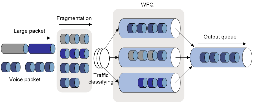
Procedure
1. Enter system view.
system-view
2. Enter VT interface, MP-group interface, or dialer interface view.
interface { dialer | mp-group | virtual-template } mp-number
3. Enable LFI.
ppp mp lfi enable
By default, LFI is disabled.
Disabling LFI also removes the user-configured settings of the maximum LFI fragment delay and size.
4. Set the maximum LFI fragment transmission delay and the maximum LFI fragment size (in bytes).
¡ Set the maximum LFI fragment transmission delay.
ppp mp lfi delay-per-frag time
By default, the maximum LFI fragment transmission delay is 10 ms. If the maximum LFI fragment size is not configured, the maximum LFI fragment size is the expected bandwidth of the interface times the maximum delay divided by 8.
¡ Set the maximum LFI fragment size.
ppp mp lfi size-per-frag size
By default, maximum LFI fragment size is the expected bandwidth of the interface times the maximum delay divided by 8.
Display and maintenance commands for MP
Execute display commands in any view and reset commands in user view.
|
Task |
Command |
|
Display information about one or all MP-group interfaces. |
display interface [ mp-group [ interface-number ] ] [ brief [ description | down ] ] |
|
Display MP information. |
display ppp mp [ interface interface-type interface-number ] |
|
Clear the statistics for MP-group interfaces. |
reset counters interface [ mp-group [ interface-number ] ] |
MP configuration examples
Example: Binding the physical interfaces to a VT interface
Network configuration
As shown in Figure 9, to enable MP for Serial 2/1/0 and Serial 2/1/1, bind the physical interfaces to a VT interface.

Procedure
1. Configure Router A:
# Create a VT interface, and configure an IP address for it.
<RouterA> system-view
[RouterA] interface virtual-template 1
[RouterA-Virtual-Template1] ip address 8.1.1.1 24
[RouterA-Virtual-Template1] quit
# Configure Serial 2/1/1.
[RouterA] interface serial 2/1/1
[RouterA-Serial2/1/1] link-protocol ppp
[RouterA-Serial2/1/1] ppp mp virtual-template 1
[RouterA-Serial2/1/1] quit
# Configure Serial 2/1/0.
[RouterA] interface serial 2/1/0
[RouterA-Serial2/1/0] link-protocol ppp
[RouterA-Serial2/1/0] ppp mp virtual-template 1
[RouterA-Serial2/1/0] quit
2. Configure Router B:
# Create a VT interface, and configure an IP address for it.
<RouterB> system-view
[RouterB] interface virtual-template 1
[RouterB-Virtual-Template1] ip address 8.1.1.2 24
[RouterB-Virtual-Template1] quit
# Configure Serial 2/1/1.
[RouterB] interface serial 2/1/1
[RouterB-Serial2/1/1] link-protocol ppp
[RouterB-Serial2/1/1] ppp mp virtual-template 1
[RouterB-Serial2/1/1] quit
# Configure Serial 2/1/0.
[RouterB] interface serial 2/1/0
[RouterB-Serial2/1/0] link-protocol ppp
[RouterB-Serial2/1/0] ppp mp virtual-template 1
[RouterB-Serial2/1/0] quit
Verifying the configuration
1. Verify binding results on Router A:
# Display MP information on Router A.
[RouterA] display ppp mp
Template: Virtual-Template1
max-bind: 16, fragment: enabled, min-fragment: 128
Master link: Virtual-Access0, Active members: 2, Bundle RouterB
Peer's endPoint descriptor: RouterB
Sequence format: long (rcv)/long (sent)
Bundle Up Time: 2013/01/10 07:13:10:723
0 lost fragments, 0 reordered, 0 unassigned, 0 interleaved
Sequence: 0 (rcv)/0 (sent)
Active member channels: 2 members
Serial2/1/1 Up-Time:2013/01/10 07:13:10:724
Serial2/1/0 Up-Time:2013/01/10 07:13:11:945
# Display the status of the VA interface on Router A.
[RouterA] display interface virtual-access
Virtual-Access0
Current state: UP
Line protocol state: UP
Description: Virtual-Access0 Interface
Bandwidth: 128kbps
Maximum transmission unit: 1500
Hold timer: 10 seconds, retry times: 5
Internet address: 8.1.1.1/24 (primary)
Link layer protocol: PPP
LCP: opened, MP: opened, IPCP: opened
Physical: MP, baudrate: 128000 bps
Main interface: Virtual-Template1
Output queue - Urgent queuing: Size/Length/Discards 0/1024/0
Output queue - Protocol queuing: Size/Length/Discards 0/500/0
Output queue - FIFO queuing: Size/Length/Discards 0/75/0
Last 300 seconds input rate: 0 bytes/sec, 0 bits/sec, 0 packets/sec
Last 300 seconds output rate: 0 bytes/sec, 0 bits/sec, 0 packets/sec
Input: 2 packets, 80 bytes, 0 drops
Output: 2 packets, 24 bytes, 0 drops
2. Ping IP address 8.1.1.1 on Router B.
[RouterB] ping 8.1.1.1
Ping 8.1.1.1 (8.1.1.1): 56 data bytes, press CTRL_C to break
56 bytes from 8.1.1.1: icmp_seq=0 ttl=255 time=4.000 ms
56 bytes from 8.1.1.1: icmp_seq=1 ttl=255 time=0.000 ms
56 bytes from 8.1.1.1: icmp_seq=2 ttl=255 time=0.000 ms
56 bytes from 8.1.1.1: icmp_seq=3 ttl=255 time=0.000 ms
56 bytes from 8.1.1.1: icmp_seq=4 ttl=255 time=1.000 ms
--- Ping statistics for 8.1.1.1 ---
5 packet(s) transmitted, 5 packet(s) received, 0.0% packet loss
round-trip min/avg/max/std-dev = 0.000/1.000/4.000/1.549 ms
Example: Associating remote usernames with a VT interface
Network configuration
As shown in Figure 10, to enable MP for Serial 2/1/0 and Serial 2/1/1, associate remote usernames with a VT interface.

Procedure
1. Configure Router A:
# Configure the username and password of the remote user for Router B on Router A.
<RouterA> system-view
[RouterA] local-user usera class network
[RouterA-luser-network-usera] password simple 123456TESTplat&!
[RouterA-luser-network-usera] service-type ppp
[RouterA-luser-network-usera] quit
# Bind a VT interface to users.
[RouterA] ppp mp user usera bind virtual-template 1
# Create the VT interface and configure its IP address.
[RouterA] interface virtual-template 1
[RouterA-Virtual-Template1] ip address 8.1.1.1 24
[RouterA-Virtual-Template1] ppp mp binding-mode authentication
[RouterA-Virtual-Template1] quit
# Configure Serial 2/1/1.
[RouterA] interface serial 2/1/1
[RouterA-Serial2/1/1] link-protocol ppp
[RouterA-Serial2/1/1] ppp authentication-mode pap
[RouterA-Serial2/1/1] ppp pap local-user userb password simple 123456TESTplat&!
[RouterA-Serial2/1/1] ppp mp
[RouterA-Serial2/1/1] quit
# Configure Serial 2/1/0.
[RouterA] interface serial 2/1/0
[RouterA-Serial2/1/0] link-protocol ppp
[RouterA-Serial2/1/0] ppp authentication-mode pap
[RouterA-Serial2/1/0] ppp pap local-user userb password simple 123456TESTplat&!
[RouterA-Serial2/1/0] ppp mp
[RouterA-Serial2/1/0] quit
2. Configure Router B:
# Configure the username and password of the remote user for Router A on Router B.
<RouterB> system-view
[RouterB] local-user userb class network
[RouterB-luser-network-userb] password simple 123456TESTplat&!
[RouterB-luser-network-userb] service-type ppp
[RouterB-luser-network-userb] quit
# Bind a VT interface to users.
[RouterB] ppp mp user userb bind virtual-template 1
# Create the VT interface and configure its IP address.
[RouterB] interface virtual-template 1
[RouterB-Virtual-Template1] ip address 8.1.1.2 24
[RouterB-Virtual-Template1] ppp mp binding-mode authentication
[RouterB-Virtual-Template1] quit
# Configure Serial 2/1/1.
[RouterB] interface serial 2/1/1
[RouterB-Serial2/1/1] link-protocol ppp
[RouterB-Serial2/1/1] ppp authentication-mode pap
[RouterB-Serial2/1/1] ppp pap local-user usera password simple 123456TESTplat&!
[RouterB-Serial2/1/1] ppp mp
[RouterB-Serial2/1/1] quit
# Configure Serial 2/1/0.
[RouterB] interface serial 2/1/0
[RouterB-Serial2/1/0] link-protocol ppp
[RouterB-Serial2/1/0] ppp authentication-mode pap
[RouterB-Serial2/1/0] ppp pap local-user usera password simple 123456TESTplat&!
[RouterB-Serial2/1/0] ppp mp
[RouterB-Serial2/1/0] quit
Verifying the configuration
1. Verify binding results on Router A:
# Display the MP information on Router A.
[RouterA] display ppp mp
Template: Virtual-Template1
max-bind: 16, fragment: enabled, min-fragment: 128
Master link: Virtual-Access0, Active members: 2, Bundle usera
Peer's endPoint descriptor: RouterB
Sequence format: long (rcv)/long (sent)
Bundle Up Time: 2013/01/10 08:02:34:881
0 lost fragments, 0 reordered, 0 unassigned, 0 interleaved
Sequence: 0 (rcv)/0 (sent)
Active member channels: 2 members
Serial2/1/1 Up-Time:2013/01/10 08:02:34:881
Serial2/1/0 Up-Time:2013/01/10 08:06:26:634
2. Verify binding results on Router B:
# Display the MP information on Router B.
[RouterB] display ppp mp
Template: Virtual-Template1
max-bind: 16, fragment: enabled, min-fragment: 128
Master link: Virtual-Access0, Active members: 2, Bundle userb
Peer's endPoint descriptor: RouterA
Sequence format: long (rcv)/long (sent)
Bundle Up Time: 2013/01/10 12:31:13:391
0 lost fragments, 0 reordered, 0 unassigned, 0 interleaved
Sequence: 0 (rcv)/0 (sent)
Active member channels: 2 members
Serial2/1/1 Up-Time:2013/01/10 12:31:13:392
Serial2/1/0 Up-Time:2013/01/10 12:35:05:892
# Display the status of the VA interfaces on Router B.
[RouterB] display interface virtual-access
Virtual-Access2
Current state: UP
Line protocol state: UP
Description: Virtual-Access0 Interface
Bandwidth: 64kbps
Maximum transmission unit: 1500
Hold timer: 10 seconds, retry times: 5
Internet address: 8.1.1.2/24 (primary)
Link layer protocol: PPP
LCP: opened, MP: opened, IPCP: opened
Physical: MP, baudrate: 64000 bps
Main interface: Virtual-Template1
Output queue - Urgent queuing: Size/Length/Discards 0/1024/0
Output queue - Protocol queuing: Size/Length/Discards 0/500/0
Output queue - FIFO queuing: Size/Length/Discards 0/75/0
Last 300 seconds input rate: 0 bytes/sec, 0 bits/sec, 0 packets/sec
Last 300 seconds output rate: 0 bytes/sec, 0 bits/sec, 0 packets/sec
Input: 2 packets, 80 bytes, 0 drops
Output: 2 packets, 24 bytes, 0 drops
# Ping IP address 8.1.1.1 on Router B.
[RouterB] ping 8.1.1.1
Ping 8.1.1.1 (8.1.1.1): 56 data bytes, press CTRL_C to break
56 bytes from 8.1.1.1: icmp_seq=0 ttl=255 time=0.000 ms
56 bytes from 8.1.1.1: icmp_seq=1 ttl=255 time=0.000 ms
56 bytes from 8.1.1.1: icmp_seq=2 ttl=255 time=1.000 ms
56 bytes from 8.1.1.1: icmp_seq=3 ttl=255 time=1.000 ms
56 bytes from 8.1.1.1: icmp_seq=4 ttl=255 time=0.000 ms
--- Ping statistics for 8.1.1.1 ---
5 packet(s) transmitted, 5 packet(s) received, 0.0% packet loss
round-trip min/avg/max/std-dev = 0.000/0.400/1.000/0.490 ms
Example: Configuring an MP-group interface
Network configuration
As shown in Figure 11, to enable MP for Serial 2/1/0 and Serial 2/1/1, configure an MP-group interface.

Procedure
1. Configure Router A:
# Create an MP-group interface, and configure an IP address for it.
<RouterA> system-view
[RouterA] interface mp-group 2/0/0
[RouterA-MP-group2/0/0] ip address 1.1.1.1 24
# Configure interface Serial 2/1/1.
[RouterA-MP-group2/0/0] quit
[RouterA] interface serial 2/1/1
[RouterA-Serial2/1/1] link-protocol ppp
[RouterA-Serial2/1/1] ppp mp mp-group 2/0/0
[RouterA-Serial2/1/1] shutdown
[RouterA-Serial2/1/1] undo shutdown
[RouterA-Serial2/1/1] quit
# Configure interface Serial 2/1/0.
[RouterA] interface serial 2/1/0
[RouterA-Serial2/1/0] link-protocol ppp
[RouterA-Serial2/1/0] ppp mp mp-group 2/0/0
[RouterA-Serial2/1/0] shutdown
[RouterA-Serial2/1/0] undo shutdown
[RouterA-Serial2/1/0] quit
2. Configure Router B:
# Create an MP-group interface, and configure an IP address for it.
[RouterB] interface mp-group 2/0/0
[RouterB-MP-group2/0/0] ip address 1.1.1.2 24
[RouterB-MP-group2/0/0] quit
# Configure interface Serial 2/1/1.
[RouterB] interface serial 2/1/1
[RouterB-Serial2/1/1] link-protocol ppp
[RouterB-Serial2/1/1] ppp mp mp-group 2/0/0
[RouterB-Serial2/1/1] shutdown
[RouterB-Serial2/1/1] undo shutdown
[RouterB-Serial2/1/1] quit
# Configure interface Serial 2/1/0.
[RouterB] interface serial 2/1/0
[RouterB-Serial2/1/0] link-protocol ppp
[RouterB-Serial2/1/0] ppp mp mp-group 2/0/0
[RouterB-Serial2/1/0] shutdown
[RouterB-Serial2/1/0] undo shutdown
[RouterB-Serial2/1/0] quit
Verifying the configuration
# Display MP information on Router A.
[RouterA] display ppp mp
Template: MP-group2/0/0
max-bind: 16, fragment: enabled, min-fragment: 128
Master link: MP-group2/0/0, Active members: 2, Bundle Multilink
Peer's endPoint descriptor: MP-group2/0/0
Sequence format: short (rcv)/long (sent)
Bundle Up Time: 2012/11/04 09:03:16:612
0 lost fragments, 0 reordered, 0 unassigned, 0 interleaved
Sequence: 0 (rcvd)/0 (sent)
Active member channels: 2 members
Serial2/1/1 Up-Time:2012/11/04 09:03:16:613
Serial2/1/0 Up-Time:2012/11/04 09:03:42:945
# Display information about interface MP-group 2/0/0 on Router A.
[RouterA] display interface mp-group 2/0/0
MP-group2/0/0
Current state: UP
Line protocol state: UP
Description: MP-group2/0/0 Interface
Bandwidth: 2048kbps
Maximum transmission unit: 1500
Hold timer: 10 seconds, retry times: 5
Internet address: 1.1.1.1/24 (primary)
Link layer protocol: PPP
LCP: opened, MP: opened, IPCP: opened
Physical: MP, baudrate: 2048000 bps
Output queue - Urgent queuing: Size/Length/Discards 0/1024/0
Output queue - Protocol queuing: Size/Length/Discards 0/500/0
Output queue - FIFO queuing: Size/Length/Discards 0/75/0
Last link flapping: Never
Last clearing of counters: Never
Last 300 seconds input rate: 0 bytes/sec, 0 bits/sec, 0 packets/sec
Last 300 seconds output rate: 0 bytes/sec, 0 bits/sec, 0 packets/sec
Input: 2 packets, 80 bytes, 0 drops
Output: 2 packets, 24 bytes, 0 drops
# Ping Router B from Router A.
[RouterA] ping 1.1.1.2
Ping 1.1.1.2 (1.1.1.2): 56 data bytes, press CTRL_C to break
56 bytes from 1.1.1.2: icmp_seq=0 ttl=255 time=4.000 ms
56 bytes from 1.1.1.2: icmp_seq=1 ttl=255 time=1.000 ms
56 bytes from 1.1.1.2: icmp_seq=2 ttl=255 time=0.000 ms
56 bytes from 1.1.1.2: icmp_seq=3 ttl=255 time=7.000 ms
56 bytes from 1.1.1.2: icmp_seq=4 ttl=255 time=1.000 ms
--- Ping statistics for 1.1.1.2 ---
5 packet(s) transmitted, 5 packet(s) received, 0.0% packet loss
round-trip min/avg/max/std-dev = 0.000/2.600/7.000/2.577 ms
Configuring PPPoE
About PPPoE
Point-to-Point Protocol over Ethernet (PPPoE) extends PPP by transporting PPP frames encapsulated in Ethernet over point-to-point links.
PPPoE specifies the methods for establishing PPPoE sessions and encapsulating PPP frames over Ethernet. PPPoE requires a point-to-point relationship between peers instead of a point-to-multipoint relationship as in multi-access environments such as Ethernet. PPPoE provides Internet access for the hosts in an Ethernet through a remote access device and implement access control, authentication, and accounting on a per-host basis. Integrating the low cost of Ethernet and scalability and management functions of PPP, PPPoE gained popularity in various application environments, such as residential access networks.
For more information about PPPoE, see RFC 2516.
PPPoE network structure
PPPoE uses the client/server model. The PPPoE client initiates a connection request to the PPPoE server. After session negotiation between them is complete, a session is established between them, and the PPPoE server provides access control, authentication, and accounting to the PPPoE client.
PPPoE network structures are classified into router-initiated and host-initiated network structures depending on the starting point of the PPPoE session.
Router-initiated network structure
As shown in Figure 12, the PPPoE session is established between devices (Device A and Device B). All hosts share one PPPoE session for data transmission without being installed with PPPoE client software. This network structure is typically used by enterprises.
Figure 12 Router-initiated network structure
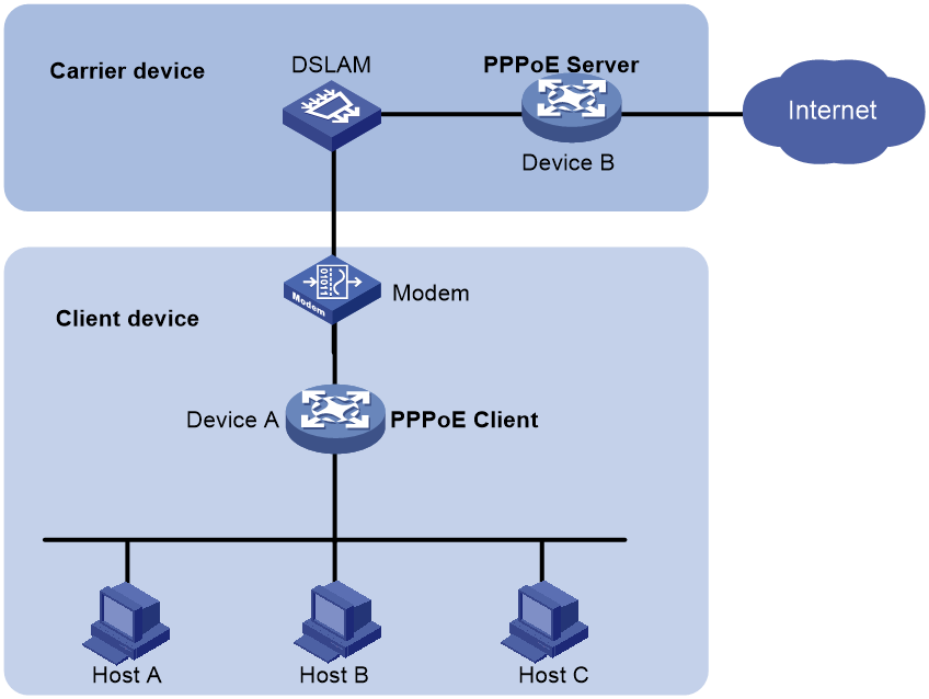
Host-initiated network structure
As shown in Figure 13, a PPPoE session is established between each host (PPPoE client) and the carrier device (PPPoE server). The service provider assigns an account to each host for billing and control. The host must be installed with PPPoE client software.
Figure 13 Host-initiated network structure
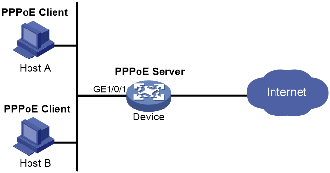
Protocols and standards
RFC 2516: A Method for Transmitting PPP Over Ethernet (PPPoE)
Restrictions: Hardware compatibility with PPPoE
Devices operating in IRF mode do not support this feature.
The following compatibility matrixes show the support of hardware platforms for PPPoE:
|
Hardware |
PPPoE compatibility |
|
MSR810, MSR810-W, MSR810-W-DB, MSR810-LM, MSR810-W-LM, MSR810-10-PoE, MSR810-LM-HK, MSR810-W-LM-HK, MSR810-LM-CNDE-SJK, MSR810-CNDE-SJK |
Yes |
|
MSR810-LMS, MSR810-LUS |
No |
|
MSR810-LMS-EA, MSR810-LME |
Yes |
|
MSR1004S-5G |
Yes |
|
MSR2600-6-X1, MSR2600-10-X1, MSR2600-15-X1 |
Yes |
|
MSR 2630 |
Yes |
|
MSR3600-28, MSR3600-51 |
Yes |
|
MSR3600-28-SI, MSR3600-51-SI |
No |
|
MSR3600-28-X1, MSR3600-28-X1-DP, MSR3600-51-X1, MSR3600-51-X1-DP |
Yes |
|
MSR3610-I-DP, MSR3610-IE-DP, MSR3610-IE-ES, MSR3610-IE-EAD, MSR-EAD-AK770, MSR3610-I-IG, MSR3610-IE-IG |
Yes |
|
MSR3610-X1, MSR3610-X1-DP, MSR3610-X1-DC, MSR3610-X1-DP-DC, MSR3620-X1, MSR3640-X1 |
Yes |
|
MSR 3610, MSR 3620, MSR 3620-DP, MSR 3640, MSR 3660 |
Yes |
|
MSR3610-G, MSR3620-G |
Yes |
|
MSR3640-X1-HI |
Yes |
|
Hardware |
PPPoE compatibility |
|
MSR810-W-WiNet, MSR810-LM-WiNet |
Yes |
|
MSR830-4LM-WiNet |
Yes |
|
MSR830-5BEI-WiNet, MSR830-6EI-WiNet, MSR830-10BEI-WiNet |
Yes |
|
MSR830-6BHI-WiNet, MSR830-10BHI-WiNet |
Yes |
|
MSR2600-6-WiNet, MSR2600-10-X1-WiNet |
Yes |
|
MSR2630-WiNet |
Yes |
|
MSR3600-28-WiNet |
Yes |
|
MSR3610-X1-WiNet |
Yes |
|
MSR3610-WiNet, MSR3620-10-WiNet, MSR3620-DP-WiNet, MSR3620-WiNet, MSR3660-WiNet |
Yes |
|
Hardware |
PPPoE compatibility |
|
MSR2630-XS |
Yes |
|
MSR3600-28-XS |
Yes |
|
MSR3610-XS |
Yes |
|
MSR3620-XS |
Yes |
|
MSR3610-I-XS |
Yes |
|
MSR3610-IE-XS |
Yes |
|
MSR3620-X1-XS |
Yes |
|
MSR3640-XS |
Yes |
|
MSR3660-XS |
Yes |
|
Hardware |
PPPoE compatibility |
|
MSR810-LM-GL |
Yes |
|
MSR810-W-LM-GL |
Yes |
|
MSR830-6EI-GL |
Yes |
|
MSR830-10EI-GL |
Yes |
|
MSR830-6HI-GL |
Yes |
|
MSR830-10HI-GL |
Yes |
|
MSR1004S-5G-GL |
Yes |
|
MSR2600-6-X1-GL |
Yes |
|
MSR3600-28-SI-GL |
No |
Restrictions and guidelines for PPPoE
The PPPoE server feature supports the following interface views:
· Layer 3 Ethernet interface/subinterface view
· Layer 3 aggregate interface/subinterface view
· VEth interface/subinterface view
· VLAN interface view
· L3VE interface/subinterface view
· EFM interface/subinterface view
Configuring the PPPoE server
PPPoE server tasks at a glance
To configure PPPoE server, perform the following tasks:
1. Configuring a PPPoE session
2. (Optional.) Configuring a VA pool
3. (Optional.) Enabling the function of querying and configuring VA interfaces through MIB nodes
4. (Optional.) Setting the maximum number of PPPoE sessions
5. (Optional.) Limiting the PPPoE access rate
6. (Optional.) Configuring the NAS-Port-ID attribute
Configuring a PPPoE session
1. Enter system view.
system-view
2. Create a VT interface and enter VT interface view.
interface virtual-template number
3. Set PPP parameters.
For more information setting PPP parameters, see "Configuring PPP."
When configuring PPP authentication, use the PPPoE server as the authenticator.
4. Enable MRU verification for PPPoE applications.
ppp lcp echo mru verify [ minimum value ]
By default, MRU verification is disabled for PPPoE applications.
5. Return to system view.
quit
6. Enter interface view.
interface interface-type interface-number
7. Enable the PPPoE server on the interface and bind this interface to the specified VT interface.
pppoe-server bind virtual-template number
By default, the PPPoE server is disabled on the interface.
8. (Optional.) Configure an access concentrator (AC) name for the PPPoE server.
pppoe-server tag ac-name name
By default, the AC name for the PPPoE server is the device name.
PPPoE clients can choose a PPPoE server according to the AC name. The PPPoE client on H3C devices do not support this feature.
9. (Optional.) Enable the PPPoE server to support the ppp-max-payload tag and specify a range for the PPP maximum payload.
pppoe-server tag ppp-max-payload [ minimum minvalue maximum maxvalue ]
By default, The PPPoE server does not support the ppp-max-payload tag.
10. (Optional.) Set a service name for the PPPoE server
pppoe-server tag service-name name
By default, the PPPoE server does not have a service name.
11. (Optional) Set the response delay time for user access.
pppoe-server access-delay delay-time
By default, no response delay time is set.
12. Return to system view.
quit
13. Configure the PPPoE server to perform authentication, authorization, and accounting for PPP users.
For more information, see Security Configuration Guide.
Configuring a VA pool
About this task
The PPPoE server creates a VA interface for a PPPoE session to transmit packets between PPPoE and PPP, and removes the VA interface when the user goes offline. Creating and removing VA interfaces take time.
You can configure VA pools to improve the performance of PPPoE session establishment and termination. A VA pool contains a group of automatically numbered VA interfaces. The PPPoE server selects a VA interface from the pool for a requesting user and release the VA interface when the user goes offline. When a VA pool is exhausted, the system creates VA interfaces for new PPPoE sessions, and removes those VA interfaces when the users go offline.
On a VT interface, you can create one global VA pool and one regional VA pool per member device for interfaces bound with the VT interface.
· The global VA pool contains VA interfaces for logical interfaces that might span multiple devices, such as Ethernet aggregate interfaces.
· The regional VA pool contains VA interfaces for interfaces that do not span multiple devices, such as Ethernet interfaces.
Restrictions and guidelines
To change the capacity of a VA pool, you must delete the previous configuration and reconfigure the VA pool.
Creating or removing a VA pool takes time. During the process of creating or removing a VA pool, users can go online or offline, but the VA pool does not take effect.
If the system fails to create a VA pool because of insufficient resources, you can view the available resources by using the display pppoe-server va-pool command.
VA pools are memory intensive. Set their capacity depending on your network requirements.
Deleting a VA pool does not log off the users who are using VA interfaces in the VA pool.
Procedure
1. Enter system view.
system-view
2. Create a VA pool.
In standalone mode:
pppoe-server virtual-template template-number va-pool va-volume
In IRF mode:
pppoe-server virtual-template template-number [ slot slot-number ] va-pool va-volume
Enabling the function of querying and configuring VA interfaces through MIB nodes
About this task
When a large VA pool is configured or a large number of users come online, a large number of VA interfaces are created on the device. In most cases, the administrator is not concerned with VA interfaces when obtaining device information through MIB nodes. Therefore, you cannot query and configure VA interfaces through MIB nodes by default. In this case, the device ignores the VA interface configuration and query requests from the NMS. This improves the efficiency of obtaining information about the other interfaces, improves the user experience, reduces the device workload, and saves CPU resources.
To query and configure VA interfaces through MIB nodes, enable this function.
Procedure
1. Enter system view.
system-view
2. Enable the function of querying and configuring VA interfaces through MIB nodes.
snmp virtual-access visible
By default, the function of querying and configuring VA interfaces through MIB nodes is disabled.
For more information about this command, see SNMP in Network Management and Monitoring Command Reference.
Setting the maximum number of PPPoE sessions
About this task
PPPoE can establish a session when none of the following limits are reached:
· Limit for a user on an interface.
· Limit for a VLAN on an interface.
· Limit on an interface.
· (In IRF mode.) Limit on an IRF member device.
· (In standalone mode.) Limit on a device.
Restrictions and guidelines for maximum number of PPPoE sessions
New maximum number settings apply only to subsequently established PPPoE sessions.
Setting the maximum number of PPPoE sessions in interface view
1. Enter system view.
system-view
2. Enter interface view.
interface interface-type interface-number
The PPPoE server is enabled on the interface.
3. Set the maximum number of PPPoE sessions.
¡ Set the maximum number of PPPoE sessions on an interface.
pppoe-server session-limit number
By default, the number of PPPoE sessions on an interface is not limited.
¡ Set the maximum number of PPPoE sessions for a VLAN.
pppoe-server session-limit per-vlan number
By default, the number of PPPoE sessions for a VLAN on an interface is not limited.
¡ Set the maximum number of PPPoE sessions for a user.
pppoe-server session-limit per-mac number
By default, a user is allowed to create a maximum of 100 PPPoE sessions.
Setting the maximum number of PPPoE sessions in system view
1. Enter system view.
system-view
2. Set the maximum number of PPPoE sessions.
In standalone mode:
pppoe-server session-limit total number
In IRF mode:
pppoe-server session-limit slot slot-number total number
By default, the number of PPPoE sessions is not limited.
Limiting the PPPoE access rate
About this task
The device can limit the rate at which a user (identified by an MAC address) can create PPPoE sessions on an interface. If the number of PPPoE requests within the monitoring time exceeds the configured threshold, the device discards the excessive requests, and outputs log messages. If the blocking time is set to 0, the device does not block any requests, and it only outputs log messages.
The device uses a monitoring table and a blocking table to control PPP access rates:
· Monitoring table—Stores a maximum of 8000 monitoring entries. Each entry records the number of PPPoE sessions created by a user within the monitoring time. When the monitoring entries reach the maximum, the system stops monitoring and blocking session requests from new users. The aging time of monitoring entries is determined by the session-request-period argument. When the timer expires, the system starts a new round of monitoring for the user.
· Blocking table—Stores a maximum of 8000 blocking entries. The system creates a blocking entry if the access rate of a user reaches the threshold, and blocks requests from that user. When the blocking entries reach the maximum number, the system stops blocking session requests from new users and it only outputs log messages. The aging time of the blocking entries is determined by the blocking-period argument. When the timer expires, the system starts a new round of monitoring for the user.
Restrictions and guidelines
If the access rate setting is changed, the system removes all monitoring and blocking entries, and uses the new settings to limit PPPoE access rates.
Procedure
1. Enter system view.
system-view
2. Enter interface view.
interface interface-type interface-number
The PPPoE server is enabled on the interface.
3. Set the PPPoE access limit.
pppoe-server throttle per-mac session-requests session-request-period blocking-period
By default, the PPPoE access rate is not limited.
Configuring the NAS-Port-ID attribute
About this task
The PPPoE server on a BAS device uses the RADIUS NAS-Port-ID attribute to send the access line ID received from a DSLAM device to the RADIUS server. The access line ID includes the circuit-id and remote-id. The RADIUS server compares the received NAS-Port-ID attribute with the local line ID information to verify the location of the user.
You can configure the content of the NAS-Port-ID attribute that the PPPoE server sends to the RADIUS server.
Procedure
1. Enter system view.
system-view
2. Enter interface view.
interface interface-type interface-number
The PPPoE server is enabled on the interface.
3. Configure the content of the NAS-Port-ID attribute.
pppoe-server access-line-id content { all [ separator ] | circuit-id | remote-id }
By default, the NAS-Port-ID attribute contains only the circuit-id.
4. Configure the NAS-Port-ID attribute to include the BAS information automatically.
pppoe-server access-line-id bas-info [ cn-163 ]
By default, the NAS-Port-ID attribute does not include the BAS information automatically.
5. Configure the PPPoE server to trust the access line ID in received packets.
pppoe-server access-line-id trust
By default, the PPPoE server does not trust the access line ID in received packets.
6. Configure the format that is used to parse the circuit-id.
pppoe-server access-line-id circuit-id parse-mode { cn-telecom | tr-101 }
The default mode is TR-101.
7. Configure the transmission format for the circuit-id.
pppoe-server access-line-id circuit-id trans-format { ascii | hex }
The default format is a string of characters.
8. Configure the transmission format for the remote-id.
pppoe-server access-line-id remote-id trans-format { ascii | hex }
The default format is a string of characters.
Configuring a PPPoE client
Operation mode
A PPPoE session can operate in one of the following modes:
· Permanent mode—A PPPoE session is established immediately when the line is physically up. This type of session remains until the physical link comes down or until the session is disconnected.
· On-demand mode—A PPPoE session is established when there is a demand for data transmission instead of when the line is physically up. It is terminated when idled for a specific period of time.
· Diagnostic mode—A PPPoE session is established immediately after the device configurations finish. The device automatically terminates the PPPoE session and then tries to re-establish a PPPoE session at a pre-configured interval. By establishing and terminating PPPoE sessions periodically, you can monitor the operating status of the PPPoE link.
The PPPoE session operating mode is determined by your configuration on the dialer interface:
· Permanent mode—Used when you set the link idle time to 0 by using the dialer timer idle command and do not configure the dialer diagnose command.
· On-demand mode—Used when you set the link idle time to a non-zero value by using the dialer timer idle command and do not configure the dialer diagnose command.
· Diagnostic mode—Used when you configure the dialer diagnose command.
PPPoE client tasks at a glance
To configure a PPPoE client, perform the following tasks:
1. Configuring a dialer interface
2. Configuring a PPPoE session
3. (Optional.) Resetting a PPPoE session
Configuring a dialer interface
About this task
Before establishing a PPPoE session, you must first create a dialer interface and configure bundle DDR on the interface. Each PPPoE session uniquely corresponds to a dialer bundle, and each dialer bundle uniquely corresponds to a dialer interface. A PPPoE session uniquely corresponds to a dialer interface.
For more information about configuring dialer interfaces, bundle DDR, and dialer bundles, see "Configuring DDR."
Procedure
1. Enter system view.
system-view
2. Create a dialer group and configure a dial rule.
dialer-group group-number rule { ip | ipv6 } { deny | permit | acl { acl-number | name acl-name } }
Configure this command only when the PPPoE session operates in on-demand mode.
3. Create a dialer interface and enter its view.
interface dialer number
4. Assign an IP address to the interface.
ip address { address mask | ppp-negotiate }
By default, no IP address is configured.
5. Enable bundle DDR on the interface.
dialer bundle enable
By default, bundle DDR is disabled.
6. Associate the interface with the dial rule by associating the interface with the corresponding dialer group.
dialer-group group-number
By default, a dialer interface is not assigned to any dialer group.
Configure this command only when the PPPoE session operates in on-demand mode.
7. Configure the link-idle timeout timer.
dialer timer idle idle [ in | in-out ]
The default setting is 120 seconds.
When this timer is set to 0 seconds, the PPPoE session operates in permanent mode. Otherwise, the PPPoE session operates in on-demand mode.
8. Configure the DDR application to operate in diagnostic mode.
dialer diagnose [ interval interval ]
By default, the DDR application operates in non-diagnostic mode.
Execute this command only when the PPPoE session operates in diagnostic mode.
9. (Optional.) Set the auto-dial interval.
dialer timer autodial autodial-interval
The default setting is 300 seconds.
DDR starts the auto-dial timer after the link is disconnected and originates a new call when the auto-dial timer expires.
As a best practice, set a shorter auto-dial interval for DDR to soon originate a new call.
10. (Optional.) Set the MTU for the dialer interface
mtu size
By default, the MTU on a dialer interface is 1500 bytes.
The dialer interface fragments a packet that exceeds the configured MTU, and adds a 2-byte PPP header and a 6-byte PPPoE header to each fragment. You should modify the MTU of a dialer interface to make sure the total length of any fragment packet is less than the MTU of the physical interface.
Configuring a PPPoE session
About this task
After a PPPoE session is successfully established, the system automatically creates a VA interface for exchanging packets with the peer. To display information about VA interfaces, execute the display interface virtual-access command. VA interfaces cannot be manually configured.
After the PPPoE session is terminated, the corresponding VA interface is automatically deleted.
Procedure
1. Enter system view.
system-view
2. Enter interface view.
interface interface-type interface-number
3. Create a PPPoE session and specify a dialer bundle for the session.
pppoe-client dial-bundle-number number [ no-hostuniq ]
The number argument in this command must take the same value as the configured dialer interface number.
Resetting a PPPoE session
About this task
After you reset a PPPoE session in permanent mode, the device establishes a new PPPoE session when the autodial timer expires.
After you reset a PPPoE session in on-demand mode, the device establishes a new PPPoE session when there is a demand for data transmission.
Procedure
To reset a PPPoE session, execute the following command in user view:
reset pppoe-client { all | dial-bundle-number number }
Display and maintenance commands for PPPoE
Display and maintenance commands for PPPoE server
Execute display commands in any view and reset commands in user view.
|
Task |
Command |
|
Display PPPoE server negotiation packet statistics. |
In standalone mode: display pppoe-server packet statistics In IRF mode: display pppoe-server packet statistics [ slot slot-number ] |
|
Display packet statistics for PPPoE sessions. |
In standalone mode: display pppoe-server session packet [ interface interface-type interface-number ] In IRF mode: display pppoe-server session packet { slot slot-number | interface interface-type interface-number } |
|
Display summary information for PPPoE sessions. |
In standalone mode: display pppoe-server session summary [ interface interface-type interface-number ] In IRF mode: display pppoe-server session summary { slot slot-number | interface interface-type interface-number } |
|
Display information about blocked users. |
In standalone mode: display pppoe-server throttled-mac [ interface interface-type interface-number ] In IRF mode: display pppoe-server throttled-mac { slot slot-number | interface interface-type interface-number } |
|
Display VA pool information. |
display pppoe-server va-pool |
|
Clear PPPoE sessions. |
reset pppoe-server { all | interface interface-type interface-number | virtual-template number } |
|
Clear PPPoE server negotiation packet statistics. |
In standalone mode: reset pppoe-server packet statistics In IRF mode: reset pppoe-server packet statistics [ slot slot-number ] |
Display and maintenance commands for PPPoE client
Execute display commands in any view and reset commands in user view.
|
Task |
Command |
|
Display summary information for a PPPoE session. |
display pppoe-client session summary [ dial-bundle-number number ] |
|
Display the protocol packet statistics for a PPPoE session. |
display pppoe-client session packet [ dial-bundle-number number ] |
|
Clear the protocol packet statistics for a PPPoE session. |
reset pppoe-client session packet [ dial-bundle-number number ] |
PPPoE configuration examples
Example: Configuring the PPPoE server to assign IPv4 addresses through a PPP address pool
Network configuration
As shown in Figure 14, Host A and Host B run PPPoE client dialup software. The PPPoE server on the router performs local authentication and assigns IP addresses to the clients.
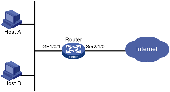
Procedure
# Create a PPPoE user.
<Router> system-view
[Router] local-user user1 class network
[Router-luser-network-user1] password simple 123456TESTplat&!
[Router-luser-network-user1] service-type ppp
[Router-luser-network-user1] quit
# Configure Virtual-Template 1 to use CHAP for authentication and use a PPP address pool for IP address assignment. Set the DNS server IP address for the peer.
[Router] interface virtual-template 1
[Router-Virtual-Template1] ppp authentication-mode chap domain system
[Router-Virtual-Template1] ppp chap user user1
[Router-Virtual-Template1] remote address pool 1
[Router-Virtual-Template1] ppp ipcp dns 8.8.8.8
[Router-Virtual-Template1] quit
# Configure a PPP address pool that contains nine assignable IP addresses, and configure a gateway address for the PPP address pool.
[Router] ip pool 1 1.1.1.2 1.1.1.10
[Router] ip pool 1 gateway 1.1.1.1
# Enable the PPPoE server on GigabitEthernet 1/0/1, and bind the interface to Virtual-Template 1.
[Router] interface gigabitethernet 1/0/1
[Router-GigabitEthernet1/0/1] pppoe-server bind virtual-template 1
[Router-GigabitEthernet1/0/1] quit
# Configure local authentication for the default ISP domain (system).
[Router] domain system
[Router-isp-system] authentication ppp local
[Router-isp-system] quit
Verifying the configuration
# Verify that Host A and Host B can access the Internet by using the username user1 and password 123456TESTplat&!. (Details not shown.)
Example: Configuring the PPPoE server to assign IPv4 addresses through the local DHCP server
Network configuration
As shown in Figure 15, configure the PPPoE server as a DHCP server to assign an IP address to the host.

Procedure
# Configure Virtual-Template 1 to use PAP for authentication and use a DHCP address pool to allocate IP addresses and DNS server IP addresses for users.
<Router> system-view
[Router] interface virtual-template 1
[Router-Virtual-Template1] ppp authentication-mode pap
[Router-Virtual-Template1] remote address pool pool1
[Router-Virtual-Template1] quit
# Enable the PPPoE server on GigabitEthernet 1/0/1, and bind the interface to Virtual-Template 1.
[Router] interface gigabitethernet 1/0/1
[Router-GigabitEthernet1/0/1] pppoe-server bind virtual-template 1
[Router-GigabitEthernet1/0/1] quit
# Enable DHCP.
[Router] dhcp enable
# Configure DHCP address pool pool1.
[Router] dhcp server ip-pool pool1
[Router-dhcp-pool-pool1] network 1.1.1.0 24
[Router-dhcp-pool-pool1] gateway-list 1.1.1.1 export-route
[Router-dhcp-pool-pool1] dns-list 8.8.8.8
# Exclude the IP address 1.1.1.1 from dynamic allocation in DHCP address pool pool1.
[Router-dhcp-pool-pool1] forbidden-ip 1.1.1.1
[Router-dhcp-pool-pool1] quit
# Create a PPPoE user.
[Router] local-user user1 class network
[Router-luser-network-user1] password simple 123456TESTplat&!
[Router-luser-network-user1] service-type ppp
[Router-luser-network-user1] quit
Verifying the configuration
# Log in to the router by using username user1 and password 123456TESTplat&!.
# Display information about IP addresses assigned by the DHCP server.
[Router] display dhcp server ip-in-use
IP address Client identifier/ Lease expiration Type
Hardware address
1.1.1.2 3030-3030-2e30-3030- Unlimited Auto(C)
662e-3030-3033-2d45-
7468-6572-6e65-74
The output shows that the router has assigned an IP address to the host.
Example: Configuring the PPPoE server to assign IPv4 addresses through a remote DHCP server
Network configuration
As shown in Figure 16, configure the PPPoE server as a DHCP relay agent to relay an IP address from the DHCP server to the host.

Procedure
1. Configure Router A as the PPPoE server:
# Configure Virtual-Template 1 to use PAP for authentication and use a DHCP address pool to allocate IP addresses and DNS server IP addresses for users.
<RouterA> system-view
[RouterA] interface virtual-template 1
[RouterA-Virtual-Template1] ppp authentication-mode pap
[RouterA-Virtual-Template1] remote address pool pool1
[RouterA-Virtual-Template1] quit
# Enable the PPPoE server on GigabitEthernet 1/0/1, and bind the interface to Virtual-Template 1.
[RouterA] interface gigabitethernet 1/0/1
[RouterA-GigabitEthernet1/0/1] pppoe-server bind virtual-template 1
[RouterA-GigabitEthernet1/0/1] quit
# Enable DHCP.
[RouterA] dhcp enable
# Enable recording of relay entries on the relay agent.
[RouterA] dhcp relay client-information record
# Create DHCP relay address pool pool1.
[RouterA] dhcp server ip-pool pool1
# Specify a gateway address for the clients in pool1.
[RouterA-dhcp-pool-pool1] gateway-list 2.2.2.1 export-route
# Specify a DHCP server for pool1.
[RouterA-dhcp-pool-pool1] remote-server 10.1.1.1
[RouterA-dhcp-pool-pool1] quit
# Specify an IP address for GigabitEthernet 1/0/2.
[RouterA] interface gigabitethernet 1/0/2
[RouterA-GigabitEthernet1/0/2] ip address 10.1.1.2 24
[RouterA-GigabitEthernet1/0/2] quit
# Create a PPPoE user.
[RouterA] local-user user1 class network
[RouterA-luser-network-user1] password simple 123456TESTplat&!
[RouterA-luser-network-user1] service-type ppp
[RouterA-luser-network-user1] quit
2. Configure Router B as a DHCP server.
# Enable DHCP.
<RouterB> system-view
[RouterB] dhcp enable
# Create DHCP address pool pool1, and specify a primary subnet and a gateway address for DHCP clients.
[RouterB] dhcp server ip-pool pool1
[RouterB-dhcp-pool-pool1] network 2.2.2.0 24
[RouterB-dhcp-pool-pool1] gateway-list 2.2.2.1
[RouterB-dhcp-pool-pool1] dns-list 8.8.8.8
# Exclude the IP address 2.2.2.1 from dynamic allocation in DHCP address pool pool1.
[RouterB-dhcp-pool-pool1] forbidden-ip 2.2.2.1
[RouterB-dhcp-pool-pool1] quit
# Specify an IP address for GigabitEthernet 1/0/1.
[RouterB] interface gigabitethernet 1/0/1
[RouterB-GigabitEthernet1/0/1] ip address 10.1.1.1 24
[RouterB-GigabitEthernet1/0/1] quit
# Configure a static route to the PPPoE server.
[RouterB] ip route-static 2.2.2.0 24 10.1.1.2
Verifying the configuration
# Log in to Router A by using username user1 and password 123456TESTplat&!.
# Display relay entries on the DHCP relay agent on Router A.
[RouterA] display dhcp relay client-information
Total number of client-information items: 1
Total number of dynamic items: 1
Total number of temporary items: 0
IP address MAC address Type Interface VPN name
2.2.2.3 00e0-0000-0001 Dynamic VA0 N/A
# Display information about the assigned IP addresses on Router B.
[RouterB] display dhcp server ip-in-use
IP address Client identifier/ Lease expiration Type
Hardware address
2.2.2.3 00e0-0000-0001 Unlimited Auto(C)
The output shows that Router B has assigned an IP address to the host.
Example: Configuring the PPPoE server to assign IPv6 addresses through ND and IPv6CP negotiation
Network configuration
As shown in Figure 17, configure the PPPoE server to advertise the following information to the host:
· IPv6 prefix in RA messages.
· IPv6 interface identifier during IPv6CP negotiation.
The host uses the IPv6 prefix and IPv6 interface identifier to generate an IPv6 global unicast address.

Procedure
# Create Virtual-Template 1.
<Router> system-view
[Router] interface virtual-template 1
# Configure Virtual-Template 1 to use PAP to authenticate the peer.
[Router-Virtual-Template1] ppp authentication-mode pap domain system
# Configure an IPv6 address for Virtual-Template 1.
[Router-Virtual-Template1] ipv6 address 2001::1 64
# Enable Virtual-Template 1 to advertise RA messages.
[Router-Virtual-Template1] undo ipv6 nd ra halt
[Router-Virtual-Template1] quit
# Enable the PPPoE sever on GigabitEthernet 1/0/1, and bind the interface to Virtual-Template 1.
[Router] interface gigabitethernet 1/0/1
[Router-GigabitEthernet1/0/1] pppoe-server bind virtual-template 1
[Router-GigabitEthernet1/0/1] quit
# Configure a PPPoE user.
[Router] local-user user1 class network
[Router-luser-network-user1] password simple 123456TESTplat&!
[Router-luser-network-user1] service-type ppp
[Router-luser-network-user1] quit
# Configure an IPv6 prefix authorized to the user in the ISP domain.
[Router] domain system
[Router-isp-system] authorization-attribute ipv6-prefix 2003:: 64
[Router-isp-system] quit
Verifying the configuration
# Display PPP user information on GigabitEthernet 1/0/1.
[Router] display ppp access-user interface gigabitethernet 1/0/1
Interface Username MAC address IP address IPv6 address IPv6 PDPrefix
VA0 user1 0000-5e08-9d00 - 2003::9CBC:3898:0:605 -
Example: Configuring the PPPoE server to assign IPv6 addresses through DHCPv6
Network configuration
As shown in Figure 18, configure the PPPoE server to assign an IPv6 address to the host through DHCPv6.

Procedure
# Create Virtual-Template 1.
<Router> system-view
[Router] interface virtual-template 1
# Configure Virtual-Template 1 to use PAP to authenticate the peer.
[Router-Virtual-Template1] ppp authentication-mode pap domain system
# Configure an IPv6 address for Virtual-Template 1.
[Router-Virtual-Template1] ipv6 address 3001::1 64
# Enable Virtual-Template 1 to advertise RA messages.
[Router-Virtual-Template1] undo ipv6 nd ra halt
# Configure the host to use the DHCPv6 protocol to obtain IPv6 addresses.
[Router-Virtual-Template1] ipv6 nd autoconfig managed-address-flag
# Enable the DHCPv6 server feature.
[Router-Virtual-Template1] ipv6 dhcp select server
[Router-Virtual-Template1] quit
# Enable the PPPoE sever on GigabitEthernet 1/0/1, and bind the interface to Virtual-Template 1.
[Router] interface gigabitethernet 1/0/1
[Router-GigabitEthernet1/0/1] pppoe-server bind virtual-template 1
[Router-GigabitEthernet1/0/1] quit
# Configure DHCPv6 address pool 1 with network 3001::/32 and DNS server IP address 2001:2::3.
[Router] ipv6 dhcp pool pool1
[Router-dhcp6-pool-pool1] network 3001::/32
[Router-dhcp6-pool-pool1] dns-server 2001:2::3
[Router-dhcp6-pool-pool1] quit
# Configure a PPPoE user.
[Router] local-user user1 class network
[Router-luser-network-user1] password simple 123456TESTplat&!
[Router-luser-network-user1] service-type ppp
[Router-luser-network-user1] quit
# Configure an IPv6 pool attribute authorized to the user in the ISP domain.
[Router] domain system
[Router-isp-system] authorization-attribute ipv6-pool pool1
[Router-isp-system] quit
Verifying the configuration
# Display PPP user information on GigabitEthernet 1/0/1.
[Router] display ppp access-user interface gigabitethernet 1/0/1
Interface Username MAC address IP address IPv6 address IPv6 PDPrefix
VA0 user1 0000-5e08-9d00 - 3001::2 -
Example: Configuring the PPPoE server to assign IPv6 addresses through prefix delegation by DHCPv6
Network configuration
As shown in Figure 19, configure the PPPoE server to assign a prefix to Router A through DHCPv6. Router A then assigns the prefix to the host for it to generate an IPv6 address.

Procedure
1. Configure Router B (PPPoE server):
# Create Virtual-Template 1.
<RouterB> system-view
[RouterB] interface virtual-template 1
# Configure Virtual-Template 1 to use PAP to authenticate the peer.
[RouterB-Virtual-Template1] ppp authentication-mode pap domain system
# Configure an IPv6 address for Virtual-Template 1.
[RouterB-Virtual-Template1] ipv6 address 2001::1 64
# Enable Virtual-Template 1 to advertise RA messages.
[RouterB-Virtual-Template1] undo ipv6 nd ra halt
# Enable the DHCPv6 server feature.
[RouterB-Virtual-Template1] ipv6 dhcp select server
[RouterB-Virtual-Template1] quit
# Enable the PPPoE sever on GigabitEthernet 1/0/1, and bind the interface to Virtual-Template 1.
[RouterB] interface gigabitethernet 1/0/1
[RouterB-GigabitEthernet1/0/1] pppoe-server bind virtual-template 1
[RouterB-GigabitEthernet1/0/1] quit
# Create prefix pool 6, and specify prefix 4001::/32 with assigned prefix length 42.
[RouterB] ipv6 dhcp prefix-pool 6 prefix 4001::/32 assign-len 42
# Create address pool 1 and apply prefix pool 6 to address pool 1.
[RouterB] ipv6 dhcp pool pool1
[RouterB-dhcp6-pool-pool1] prefix-pool 6
[Router-dhcp6-pool-pool1] quit
# Configure a PPPoE user.
[RouterB] local-user user1 class network
[RouterB-luser-network-user1] password simple 123456TESTplat&!
[RouterB-luser-network-user1] service-type ppp
[RouterB-luser-network-user1] quit
# Configure an IPv6 pool attribute authorized to the user in the ISP domain.
[RouterB] domain system
[RouterB-isp-system] authorization-attribute ipv6-pool pool1
2. Configure Router A (PPPoE client):
# Enable bundle DDR on interface Dialer 1.
<RouterA> system-view
[RouterA] interface dialer 1
[RouterA-Dialer1] dialer bundle enable
# On Dialer 1, configure the PAP username and password sent from Router A to Router B as user1 and pass1 when Router A is authenticated by Router B by using PAP.
[RouterA-Dialer1] ppp pap local-user user1 password simple 123456TESTplat&!
# Configure the PPPoE session to operate in permanent mode.
[RouterA-Dialer1] dialer timer idle 0
# Set the DDR auto-dial interval to 60 seconds.
[RouterA-Dialer1] dialer timer autodial 60
# Configure Dialer 1 to use DHCPv6 to obtain an IPv6 address and other configuration parameters.
[RouterA-Dialer1] ipv6 address dhcp-alloc
# Configure Dialer 1 as a DHCPv6 client for IPv6 prefix acquisition. Configure the DHCPv6 client to assign ID 1 to the obtained IPv6 prefix.
[RouterA-Dialer1] ipv6 dhcp client pd 1
[RouterA-Dialer1] quit
# Configure a PPPoE session corresponding to Dialer bundle 1, which corresponds to Dialer 1.
[RouterA] interface gigabitethernet 1/0/2
[RouterA-GigabitEthernet1/0/2] pppoe-client dial-bundle-number 1
[RouterA-GigabitEthernet1/0/2] quit
# Configure a default route.
[RouterA] ipv6 route-static :: 0 dialer 1
# Enable GigabitEthernet1/0/1 to advertise RA messages.
[RouterA] interface gigabitethernet 1/0/1
[RouterA-GigabitEthernet1/0/1] undo ipv6 nd ra halt
# Configure GigabitEthernet1/0/1 to dynamically obtain IPv6 prefix 1 (use IPv6 prefix 1 to generate IPv6 address 123::123:1:1/64) and advertise IPv6 prefix 1 to endpoints through RA messages.
[RouterA-GigabitEthernet1/0/1] ipv6 address 1 123::123:1:1/64
[RouterA-GigabitEthernet1/0/1] quit
Verifying the configuration
# Display information about prefixes on Router A.
[RouterA] display ipv6 prefix
Number Prefix Type
1 4001::/42 Dynamic
The output shows that Router A has created prefix 1 based on the ipv6 dhcp client pd 1 command after obtaining a prefix from Router B.
Then, Router A can assign the prefix 4001::/42 to the host who uses the prefix to generate an IPv6 global unicast address.
Example: Configuring PPPoE server to assign address pools and VPNs
Network configuration
As shown in Figure 20, configure the PPPoE server to meet the following requirements:
· The PPPoE server uses the RADIUS server to perform authentication, authorization, and accounting for access users
· The RADIUS server assigns access users a PPP address pool named pool1 and a VPN instance named vpn1.
· Users in vpn1 obtain IP addresses from PPP address pool pool1.
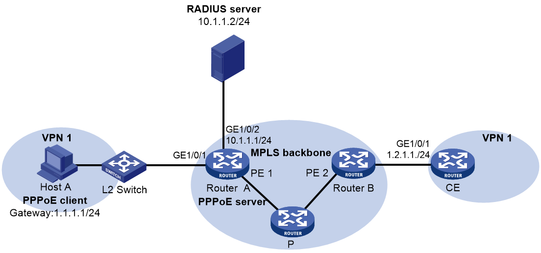
Procedure
1. Configure the MPLS L3VPN feature.
For the two ends of VPN 1 to communicate with each other, specify the same route target attributes on the two PEs (Router A and Router B). This example describes only the authentication-related configuration on the PE that is connected to the PPPoE client. For information about configuring MPLS L3VPN, see MPLS Configuration Guide.
2. Configure the RADIUS server:
This example uses Free RADIUS that runs in the Linux operating system.
# Add the following text to the client.conf file to configure RADIUS client information.
client 10.1.1.1/24 {
secret = radius
shortname = device
}
Where, secret represents the shared key for authentication, authorization, and accounting.
# Add the following text to the users.conf file to configure legal user information.
user1 Auth-Type == CHAP,User-Password := pass1
Service-Type = Framed-User,
Framed-Protocol = PPP,
Framed-Pool = "pool1",
H3C-VPN-Instance = "vpn1",
3. Configure Router A:
a. Configure the PPPoE server:
# Configure Virtual-Template 1 to use CHAP for authentication and use ISP domain dm1 as the authentication domain.
<RouterA> system-view
[RouterA] interface virtual-template 1
[RouterA-Virtual-Template1] ppp authentication-mode chap domain dm1
[RouterA-Virtual-Template1] quit
# Create a PPP address pool that contains nine assignable IP addresses.
[RouterA] ip pool pool1 1.1.1.2 1.1.1.10 group 1
# Specify gateway address 1.1.1.1 and VPN instance vpn1 for pool1.
[RouterA] ip pool pool1 gateway 1.1.1.1 vpn-instance vpn1
# Configure a PPP address pool route for pool1.
[RouterA] ppp ip-pool route 1.1.1.1 24 vpn-instance vpn1
# Enable the PPPoE server on GigabitEthernet 1/0/1, and bind the interface to Virtual-Template 1.
[RouterA] interface gigabitethernet 1/0/1
[RouterA-GigabitEthernet1/0/1] pppoe-server bind virtual-template 1
[RouterA-GigabitEthernet1/0/1] quit
b. Configure a RADIUS scheme:
# Create a RADIUS scheme named rs1, and enter its view.
[RouterA] radius scheme rs1
# Specify the primary authentication server and the primary accounting server.
[RouterA-radius-rs1] primary authentication 10.1.1.2
[RouterA-radius-rs1] primary accounting 10.1.1.2
# Set the shared key for secure communication with the server to radius in plain text.
[RouterA-radius-rs1] key authentication simple radius
[RouterA-radius-rs1] key accounting simple radius
# Exclude domain names in the usernames sent to the RADIUS server.
[RouterA-radius-rs1] user-name-format without-domain
[RouterA-radius-rs1] quit
c. Configure an authentication domain:
# Create an ISP domain named dm1.
[RouterA] domain dm1
# In ISP domain dm1, perform RADIUS authentication, authorization, and accounting for users based on scheme rs1.
[RouterA-isp-dm1] authentication ppp radius-scheme rs1
[RouterA-isp-dm1] authorization ppp radius-scheme rs1
[RouterA-isp-dm1] accounting ppp radius-scheme rs1
[RouterA-isp-dm1] quit
Verifying the configuration
# Verify that Host A can successfully ping CE. (Details not shown.)
# Verify that the PPPoE client has obtained an IP address from pool1.
[RouterA] display ip pool pool1
Group name: 1
Pool name Start IP address End IP address Free In use
pool1 1.1.1.2 1.1.1.10 8 1
In use IP addresses:
IP address Interface
1.1.1.2 VA0
Example: Configuring a PPPoE client in permanent mode
Network configuration
As shown in Figure 21, Router A serves as a PPPoE server. Configure Router B as a PPPoE client operating in permanent mode.

Procedure
1. Configure Router A as the PPPoE server:
# Configure an IP address for Virtual-Template 1 and specify an IP address for the peer.
<RouterA> system-view
[RouterA] interface virtual-template 1
[RouterA-Virtual-Template1] ip address 1.1.1.1 255.0.0.0
[RouterA-Virtual-Template1] remote address 1.1.1.2
# Configure Virtual-Template 1 to authenticate the peer by using PAP.
[RouterA-Virtual-Template1] ppp authentication-mode pap domain dm1
[RouterA-Virtual-Template1] quit
# Enable the PPPoE server on GigabitEthernet 1/0/1, and bind the interface to Virtual-Template 1.
[RouterA] interface gigabitethernet 1/0/1
[RouterA-GigabitEthernet1/0/1] pppoe-server bind virtual-template 1
[RouterA-GigabitEthernet1/0/1] quit
# Configure a PPPoE user.
[RouterA] local-user user1 class network
[RouterA-luser-network-user1] password simple 123456TESTplat&!
[RouterA-luser-network-user1] service-type ppp
[RouterA-luser-network-user1] quit
# Configure local AAA for the PPP users in ISP domain dm1.
[RouterA] domain dm1
[RouterA-isp-dm1] authentication ppp local
[RouterA-isp-dm1] accounting ppp local
[RouterA-isp-dm1] authorization ppp local
[RouterA-isp-dm1] quit
2. Configure Router B as the PPPoE client:
# Enable bundle DDR on Dialer 1.
<RouterB> system-view
[RouterB] interface dialer 1
[RouterB-Dialer1] dialer bundle enable
# Configure Dialer 1 to obtain an IP address through PPP negotiation.
[RouterB-Dialer1] ip address ppp-negotiate
# On Dialer 1, configure the PAP username and password sent from Router B to Router A as user1 and 123456TESTplat&! when Router B is authenticated by Router A by using PAP.
[RouterB-Dialer1] ppp pap local-user user1 password simple 123456TESTplat&!
[RouterB-Dialer1] quit
# Configure a PPPoE session that corresponds to dialer bundle 1 (dialer bundle 1 corresponds to Dialer 1).
[RouterB] interface gigabitethernet 1/0/1
[RouterB-GigabitEthernet1/0/1] pppoe-client dial-bundle-number 1
[RouterB-GigabitEthernet1/0/1] quit
# Configure the PPPoE session to operate in permanent mode.
[RouterB] interface dialer 1
[RouterB-Dialer1] dialer timer idle 0
# Set the DDR auto-dial interval to 60 seconds.
[RouterB-Dialer1] dialer timer autodial 60
[RouterB-Dialer1] quit
# Configure a static route.
[RouterB] ip route-static 1.1.1.1 255.0.0.0 dialer 1
Verifying the configuration
# Display summary information about the PPPoE session established between Router B and Router A (PPPoE server).
[RouterB-Dialer1] display pppoe-client session summary
Bundle ID Interface VA RemoteMAC LocalMAC State
1 1 GE1/0/1 VA0 00e0-1400-4300 00e0-1500-4100 SESSION
Example: Configuring a PPPoE client in on-demand mode
Network configuration
As shown in Figure 22, Router A serves as a PPPoE server. Configure Router B as a PPPoE client operating in on-demand mode, and set the link idle-timeout timer to 150 seconds.

Procedure
1. Configure Router A as the PPPoE server:
# Configure an IP address for Virtual-Template 1 and specify an IP address for the peer.
<RouterA> system-view
[RouterA] interface virtual-template 1
[RouterA-Virtual-Template1] ip address 1.1.1.1 255.0.0.0
[RouterA-Virtual-Template1] remote address 1.1.1.2
# Configure Virtual-Template 1 to authenticate the peer by using PAP.
[RouterA-Virtual-Template1] ppp authentication-mode pap domain dm1
[RouterA-Virtual-Template1] quit
# Enable the PPPoE server on GigabitEthernet 1/0/1, and bind the interface to Virtual-Template 1.
[RouterA] interface gigabitethernet 1/0/1
[RouterA-GigabitEthernet1/0/1] pppoe-server bind virtual-template 1
[RouterA-GigabitEthernet1/0/1] quit
# Configure a PPPoE user.
[RouterA] local-user user1 class network
[RouterA-luser-network-user1] password simple 123456TESTplat&!
[RouterA-luser-network-user1] service-type ppp
[RouterA-luser-network-user1] quit
# Configure local AAA for the PPP users in ISP domain dm1.
[RouterA] domain dm1
[RouterA-isp-dm1] authentication ppp local
[RouterA-isp-dm1] accounting ppp local
[RouterA-isp-dm1] authorization ppp local
[RouterA-isp-dm1] quit
2. Configure Router B as the PPPoE client.
# Create dialer group 1 and configure a dial rule for it.
<RouterB> system-view
[RouterB] dialer-group 1 rule ip permit
# Enable bundle DDR on Dialer 1.
[RouterB] interface dialer 1
[RouterB-Dialer1] dialer bundle enable
# Associate Dialer 1 with dialer group 1.
[RouterB-Dialer1] dialer-group 1
# Configure Dialer 1 to obtain an IP address through PPP negotiation.
[RouterB-Dialer1] ip address ppp-negotiate
# On Dialer 1, configure the PAP username and password sent from Router B to Router A as user1 and 123456TESTplat&! when Router B is authenticated by Router A by using PAP.
[RouterB-Dialer1] ppp pap local-user user1 password simple 123456TESTplat&!
[RouterB-Dialer1] quit
# Configure a PPPoE session that corresponds to dialer bundle 1 (dialer bundle 1 corresponds to Dialer 1).
[RouterB] interface gigabitethernet 1/0/1
[RouterB-GigabitEthernet1/0/1] pppoe-client dial-bundle-number 1
[RouterB-GigabitEthernet1/0/1] quit
# Configure a static route.
[RouterB] ip route-static 1.1.1.1 255.0.0.0 dialer 1
# Set the link-idle timeout timer to 150 seconds.
[RouterB] interface dialer 1
[RouterB-Dialer1] dialer timer idle 150
[RouterB-Dialer1] quit
Verifying the configuration
# Display summary information about the PPPoE session established between Router B and Router A (PPPoE server).
[RouterB-Dialer1] display pppoe-client session summary
Bundle ID Interface VA RemoteMAC LocalMAC State
1 1 GE1/0/1 VA0 00e0-1400-4300 00e0-1500-4100 SESSION
Example: Configuring a PPPoE client in diagnostic mode
Network configuration
As shown in Figure 23, Router A serves as a PPPoE server. Configure Router B as a PPPoE client operating in diagnostic mode, and set the diagnostic interval to 200 seconds.

Procedure
1. Configure Router A as the PPPoE server:
# Configure an IP address for Virtual-Template 1 and specify an IP address for the peer.
<RouterA> system-view
[RouterA] interface virtual-template 1
[RouterA-Virtual-Template1] ip address 1.1.1.1 255.0.0.0
[RouterA-Virtual-Template1] remote address 1.1.1.2
# Configure Virtual-Template 1 to authenticate the peer by using PAP.
[RouterA-Virtual-Template1] ppp authentication-mode pap domain dm1
[RouterA-Virtual-Template1] quit
# Enable the PPPoE server on GigabitEthernet 1/0/1, and bind the interface to Virtual-Template 1.
[RouterA] interface gigabitethernet 1/0/
[RouterA-GigabitEthernet1/0/1] pppoe-server bind virtual-template 1
[RouterA-GigabitEthernet1/0/1] quit
# Configure a PPPoE user.
[RouterA] local-user user1 class network
[RouterA-luser-network-user1] password simple 123456TESTplat&!
[RouterA-luser-network-user1] service-type ppp
[RouterA-luser-network-user1] quit
# Configure local AAA for the PPP users in ISP domain dm1.
[RouterA] domain dm1
[RouterA-isp-dm1] authentication ppp local
[RouterA-isp-dm1] accounting ppp local
[RouterA-isp-dm1] authorization ppp local
[RouterA-isp-dm1] quit
2. Configure Router B as the PPPoE client.
# Enable bundle DDR on Dialer 1.
<RouterB> system-view
[RouterB] interface dialer 1
[RouterB-Dialer1] dialer bundle enable
# Configure Dialer 1 to obtain an IP address through PPP negotiation.
[RouterB-Dialer1] ip address ppp-negotiate
# On Dialer 1, configure the PAP username and password sent from Router B to Router A as user1 and 123456TESTplat&! when Router B is authenticated by Router A by using PAP.
[RouterB-Dialer1] ppp pap local-user user1 password simple 123456TESTplat&!
[RouterB-Dialer1] quit
# Configure a PPPoE session that corresponds to dialer bundle 1 (dialer bundle 1 corresponds to Dialer 1).
[RouterB] interface gigabitethernet 1/0/1
[RouterB-GigabitEthernet1/0/1] pppoe-client dial-bundle-number 1
[RouterB-GigabitEthernet1/0/1] quit
# Configure the PPPoE session to operate in diagnostic mode, and set the diagnostic interval to 200 seconds.
[RouterB] interface dialer 1
[RouterB-Dialer1] dialer diagnose interval 200
# Set the DDR auto-dial interval to 10 seconds.
[RouterB-Dialer1] dialer timer autodial 10
Verifying the configuration
# Display summary information about the PPPoE session established between Router B and Router A (PPPoE server).
[RouterB-Dialer1] display pppoe-client session summary
Bundle ID Interface VA RemoteMAC LocalMAC State
1 1 GE1/0/1 VA0 00e0-1400-4300 00e0-1500-4100 SESSION
Example: Connecting a LAN to the Internet through an ADSL modem
Network configuration
As shown in Figure 24:
· Router A provides Internet access for Host A, Host B, and Host C. It connects to the DSLAM through an ADSL modem and a permanent PPPoE session.
· The username and password of the ADSL account are user1 and 123456TESTplat&!.
· Router A operates as a PPPoE client, and it allows the hosts in the LAN to access the Internet without PPPoE client software.
· Router B operates as the PPPoE server. It performs RADIUS authentication and accounting.
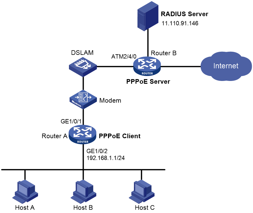
Procedure
1. Configure Router A as a PPPoE client:
# Create dialer group 1 and configure a dial rule for it.
<RouterA> system-view
[RouterA] dialer-group 1 rule ip permit
# Enable bundle DDR on Dialer 1.
[RouterA] interface dialer 1
[RouterA-Dialer1] dialer bundle enable
# Associate Dialer 1 with dialer group 1.
[RouterA-Dialer1] dialer-group 1
# Configure Dialer 1 to obtain an IP address through PPP negotiation.
[RouterA-Dialer1] ip address ppp-negotiate
# Configure the PPPoE session to operate in permanent mode.
[RouterA-Dialer1] dialer timer idle 0
# Configure the PAP username and password.
[RouterA-Dialer1] ppp pap local-user user1 password simple 123456TESTplat&!
[RouterA-Dialer1] quit
# Configure a PPPoE session.
[RouterA] interface gigabitethernet 1/0/1
[RouterA-GigabitEthernet1/0/1] pppoe-client dial-bundle-number 1
[RouterA-GigabitEthernet1/0/1] quit
# Configure an IP address for the LAN interface.
[RouterA] interface gigabitethernet 1/0/2
[RouterA-GigabitEthernet1/0/2] ip address 192.168.1.1 255.255.255.0
[RouterA-GigabitEthernet1/0/2] quit
# Configure a default route.
[RouterA] ip route-static 0.0.0.0 0 dialer 1
If the hosts in the LAN use private addresses, configure NAT on Router A. For more information about NAT, see Layer 3—IP Services Configuration Guide.
2. Configure Router B as the PPPoE server:
# Configure Virtual-Template 1 to use PAP for authentication and use a PPP address pool to assign IP addresses. Set the primary DNS server IP address for the peer.
<RouterB> system-view
[RouterB] interface virtual-template 1
[RouterB-Virtual-Template1] ppp authentication-mode pap domain system
[RouterB-Virtual-Template1] remote address pool 1
[RouterB-Virtual-Template1] ppp ipcp dns 8.8.8.8
[RouterB-Virtual-Template1] quit
# Configure a local PPP address pool that contains nine assignable IP addresses and configure a gateway address for the PPP address pool.
[RouterB] ip pool 1 1.1.1.2 1.1.1.10
[RouterB] ip pool 1 gateway 1.1.1.1
# Enable the PPPoE server on Virtual-Ethernet 1 and bind Virtual-Ethernet 1 to Virtual-Template 1.
[RouterB] interface virtual-ethernet 1
[RouterB-Virtual-Ethernet1] mac-address 0001-0000-0001
[RouterB-Virtual-Ethernet1] pppoe-server bind virtual-template 1
[RouterB-Virtual-Ethernet1] quit
# Configure an ATM interface.
[RouterB] interface atm 2/4/0.1
[RouterB-ATM2/4/0.1] pvc to_adsl_a 0/60
[RouterB-ATM2/4/0.1-pvc-to_adsl_a-0/60] map bridge virtual-ethernet 1
[RouterB-ATM2/4/0.1-pvc-to_adsl_a-0/60] quit
[RouterB-Atm2/4/0.1] quit
# Configure the default ISP domain (system) to use the RADIUS scheme for authentication, authorization, and accounting.
[RouterB] domain system
[RouterB-isp-system] authentication ppp radius-scheme rs1
[RouterB-isp-system] authorization ppp radius-scheme rs1
[RouterB-isp-system] accounting ppp radius-scheme rs1
[RouterB-isp-system] quit
# Configure a RADIUS scheme, and assign an IP address and port number for the RADIUS server.
[RouterB] radius scheme rs1
[RouterB-radius-rs1] primary authentication 11.110.91.146 1812
[RouterB-radius-rs1] primary accounting 11.110.91.146 1813
# Set the shared keys for secure communication with the RADIUS server to expert in plain text.
[RouterB-radius-rs1] key authentication simple expert
[RouterB-radius-rs1] key accounting simple expert
[RouterB-radius-rs1] quit
3. Configure the RADIUS server:
# Configure the authentication and accounting passwords as expert.
# Add a PPPoE user with username user1 and password 123456TESTplat&!.
For more information about RADIUS, see Security Configuration Guide.
Verifying the configuration
# Display summary information for the PPPoE session between Router A and Router B.
[RouterA] display pppoe-client session summary
Bundle ID Interface VA RemoteMAC LocalMAC State
1 1 GE1/0/1 VA0 0001-0000-0001 00e0-1500-4100 SESSION
Host A, Host B, and Host C can thus access the Internet. For example, they can browse a web page through IE.
