- Table of Contents
- Related Documents
-
| Title | Size | Download |
|---|---|---|
| 05-CPOS interface configuration | 179.25 KB |
Contents
CPOS interface application scenarios
Configuring the operating mode of an interface card
Configuring basic settings of a CPOS interface
Configuring overhead bytes on a CPOS interface
Enabling loopback on a CPOS interface
Restoring the default settings for an interface
Configuring basic settings of an E1 channel
Configuring overhead bytes on an E1 channel
Configuring the E1 channel alignment mode
Configuring the E1 channel operating mode
Enabling loopback on an E1 channel
Configuring basic settings of a T1 channel
Configuring overhead bytes on a T1 channel
Configuring the T1 channel operating mode
Enabling loopback on a T1 channel
Display and maintenance commands for CPOS interfaces
CPOS interface configuration examples
Example: Configuring CPOS-E1 channels
Troubleshooting CPOS interfaces
Configuring CPOS interfaces
About CPOS interfaces
Commands in this chapter are supported only when the device has related interfaces. For the interfaces that the device has, see the installation guide and interface module manuals.
The low-speed tributary signals multiplexed to form an SDH signal are called channels. The channelized POS (CPOS) interface makes full use of SDH to provide the following benefits:
· Provides precise bandwidth division.
· Reduces the number of low-speed physical interfaces on devices.
· Enhances aggregation capacity.
· Improves the access capacity of leased lines.
CPOS interface application scenarios
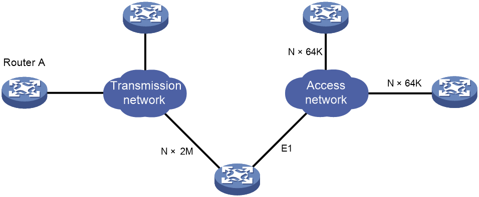
CPOS E1/T1 interfaces are typically used to aggregate E1 and T1 lines, as shown in Figure 1.
In actual applications, the connection between low-end devices and the CPOS interfaces might span more than one transmission network and might require relay.
Figure 1 CPOS E1/T1 interface application scenario
CPOS interface types
The device supports the CPOS interfaces in Table 1.
|
Interface type |
Channelization/multiplexing capabilities |
|
CPOS E1 |
63 E1 channels (E1 channel configurable). |
|
CPOS T1 |
84 T1 channels (T1 channel configurable). |
|
High-speed CPOS interfaces: |
|
CPOS E3E1 interfaces support concurrent E3 and E1 channels. CPOS T3T1 interfaces support concurrent T3 and T1 channels.
A CPOS E3E1 interface has 63 E1 channels, which are identical to 3 E3 channels. When you configure an E3 channel on the interface, the system attempts to assign 21 E1 channels to the E3 channel and reserve 21 channel numbers.
The system uses the 3 x M + N formula to reserve channel numbers in increments of 3. M represents an integer in the range of 1 to 20, and N represents the E3 channel number. For example, set the channel number of an E3 channel to 1. The system will reserve the channel numbers 4, 7, 10, and continue in increments of 3 up to 61.
You cannot assign a channel number to an E3 channel if the channel number or any channel number to be reserved has been used. After a channel number is reserved, it is not available for assignment. The system will display an error message when you attempt to use or specify a reserved channel number.
A CPOS T3T1 interface has 84 T1 channels. When you configure a T3 channel on the interface, 28 T1 channels are assigned with reserved channel numbers to the T3 channel. The CPOS T3T1 interface uses the same channel number assignment method as the CPOS E3E1 interface.
Overhead bytes
SDH provides layered precise monitoring and management.
SDH monitoring functions are implemented using overhead bytes. SDH provides monitoring at section and channel levels.
· Sections are subdivided into regenerator and multiplex sections.
· Channels are subdivided into higher-order and lower-order paths.
SDH provides a variety of overhead bytes, but only those involved in CPOS configuration are discussed in this section.
SOH
The section overhead (SOH) is further classified into the regenerator section overhead (RSOH) and the multiplex section overhead (MSOH).
The J0 regenerator section trace byte is included in RSOH to repeatedly send the section access point identifier. The receiver uses this identifier to make sure it is in continuous connection with the sender. This byte can be any character in the network of the same carrier. If the networks of two carriers are involved, the sending and receiving devices at network borders must use the same J0 byte. With the J0 byte, carriers can detect and troubleshoot faults in advance or use less time to recover networks.
POH
The payload of an STM-N frame includes the path overhead (POH), which monitors low-speed tributary signals.
The SOH monitors the section layer, and the POH monitors the path layer. The POH is divided into the higher-order path overhead and the lower-order path overhead.
Higher-order path overhead monitors paths at the VC-4/VC-3 level.
Similar to the J0 byte, the higher-order VC-N path trace byte J1 is included in the higher-order path overhead to repeatedly send the higher-order path access point identifier. The receiving end of the path uses this identifier to make sure it is in continuous connection with the specified sender. The sender and the receiver must use the same J1 byte.
In addition, the path signal label byte C2 is included in the higher-order path overhead to indicate the multiplexing structure of VC frames and the properties of payload, including the following:
· Whether the path is carrying traffic.
· What type of traffic is carried.
· How the VC frames are mapped.
The sender and receiver must use the same C2 byte.
Configuring the operating mode of an interface card
The CPOS interface cards can operate in different modes to provide different types of interfaces. To change the operating mode for a CPOS interface card, execute the card-mode command. You must make sure a CPOS interface card is operating in the desired mode before you configure the interfaces on it. For more information about interface card operating mode configuration, see device management in Fundamentals Configuration Guide.
Configuring a CPOS interface
Restrictions and guidelines
If no cable is connected to a physical interface, shut down the interface with the shutdown command to prevent problems.
Configuring basic settings of a CPOS interface
1. Enter system view.
system-view
2. Enter CPOS interface view.
controller cpos cpos-number
3. (Optional.) Configure the interface description.
description text
By default, the description of a CPOS interface is interface name Interface.
4. Set the clock mode.
clock { master | slave }
The default setting is slave.
When two CPOS interfaces are directly connected, you must configure the two ends with different clock modes.
When connected to a SONET/SDH device, the CPOS interface must use the slave clock mode. The SONET/SDH network clock is more precise.
5. Set the framing format.
frame-format { sdh | sonet }
The default setting is SDH.
6. Set the AUG multiplexing mode.
multiplex mode { au-3 | au-4 }
The default setting is AU-4.
The command is available only in SDH framing.
7. Bring up the CPOS interface.
undo shutdown
By default, a CPOS interface is up.
Configuring overhead bytes on a CPOS interface
Restrictions and guidelines
You must configure the same overhead bytes at both ends of a link.
Procedure
1. Enter system view.
system-view
2. Enter CPOS interface view.
controller cpos cpos-number
3. Configure the signal label byte (C2).
flag c2 path-number c2-value
By default, the C2 byte value is 2 (hexadecimal).
4. Configure the synchronization status byte (S1).
flag s1 s1-value
By default, the S1 byte value is f (hexadecimal).
5. Configure the AU type and TU type.
flag s1s0 path-number s1s0-value
By default, the value of S1S0 is 0 (hexadecimal) for SONET and 2 (hexadecimal) for SDH.
6. Configure the regenerator section trace message.
flag j0 { sdh | sonet } flag-value
By default, the J0 byte value is 1 (hexadecimal) for SONET and a 16-byte null string for SDH.
7. Configure the path trace message.
flag j1 path-number { sdh | sonet } flag-value
By default, the J1 byte value is a 64-byte null string for SONET and a 16-byte null string for SDH.
Enabling loopback on a CPOS interface
About this task
Perform this task to determine whether a CPOS link works correctly.
Loopback includes the following types:
· Internal loopback—Tests the device where the CPOS interface resides. The CPOS interface sends outgoing packets back to the local device. If the device fails to receive the packets, the device fails.
· External loopback—Tests the inter-device link. The CPOS interface sends incoming packets back to the remote device. If the remote device fails to receive the packets, the inter-device link fails.
Restrictions and guidelines
Loopback is intended for testing only. Disable the feature when the CPOS interface is operating properly.
After you enable this feature on a CPOS interface, the interface does not forward data traffic.
Procedure
1. Enter system view.
system-view
2. Enter CPOS interface view.
controller cpos cpos-number
3. Enable loopback.
loopback { local | remote }
By default, loopback is disabled.
Restoring the default settings for an interface
Restrictions and guidelines
This feature might interrupt ongoing network services. Make sure you are fully aware of the impact of this feature when you use it on a live network.
This feature might fail to restore the default settings for some commands because of command dependencies or system restrictions. You can use the display this command in interface view to check for these commands and perform their undo forms or follow the command reference to restore their default settings. If your restoration attempt still fails, follow the error message to resolve the problem.
Procedure
1. Enter system view.
system-view
2. Enter CPOS interface view.
controller cpos cpos-number
3. Restore the default settings for the interface.
default
Configuring an E1 channel
About E1 channels
The serial interfaces created for E1 channels have the same logical features as a synchronous serial interface. You can configure these serial interfaces in the same way you configure a standard synchronous serial interface. For more information about configuring synchronous serial interfaces, see "Configuring WAN interfaces."
Configuring basic settings of an E1 channel
1. Enter system view.
system-view
2. Enter CPOS interface view.
controller cpos cpos-number
3. Set the framing format for the E1 channel.
e1 e1-number frame-format { crc4 | no-crc4 }
The default setting is no-CRC4.
4. Set the clock mode for the E1 channel.
e1 e1-number clock { master | slave }
The default setting is slave.
5. (Optional.) Shut down the specified E1 channel.
e1 e1-number shutdown
By default, an E1 channel is up.
Configuring overhead bytes on an E1 channel
Restrictions and guidelines
You must configure the same overhead bytes at both ends of a link.
Procedure
1. Enter system view.
system-view
2. Enter CPOS interface view.
controller cpos cpos-number
3. Configure the low-order channel signal tag byte (C2).
e1 e1-number flag c2 c2-value
By default, the C2 byte value is 2 (hexadecimal).
4. Configure the low-order channel trace byte (J2).
e1 e1-number flag j2 { sdh | sonet } j2-string
By default, the cyclic value for the J2 byte is cyclic null.
Configuring the E1 channel alignment mode
About this task
For E1 channels to operate correctly, channel number assignment must meet the following requirements:
· If this feature is configured, use the same channel number assignment scheme as the peer end. For example, to communicate with channel 5 on a Lucent-mode CPOS interface, configure channel 5 on the local interface.
· If this feature is not configured, you must map the channel number assignment schemes between the two ends. For example, to communicate with channel 25 on a Lucent-mode CPOS interface, you must configure channel 5 on the local interface.
Restrictions and guidelines
You must configure this feature before using the e1 channel-set or e1 unframed command.
Procedure
1. Enter system view.
system-view
2. Enter CPOS interface view.
controller cpos cpos-number
3. Set the E1 channel alignment mode.
channel-align-mode { alcatel | lucent }
By default, the E1 channel alignment mode is H3C.
Configuring the E1 channel operating mode
About this task
E1 channels on CPOS interfaces support the unframed (clear channel) mode and the framed (channelized) mode.
· Unframed mode—An E1 channel can form a 2.048 Mbps serial interface without timeslot division. It is numbered in the format of interface-number/channel-number:0.
· Framed mode—All timeslots except timeslot 0 on the E1 channel can be bundled randomly to form serial interfaces.
Restrictions and guidelines
For successful communication, make sure the local end has the same timeslot bundling settings as the remote end.
You must configure this feature before using the e1 channel-set or e1 unframed command.
Configuring the unframed mode
1. Enter system view.
system-view
2. Enter CPOS interface view.
controller cpos cpos-number
3. Configure the unframed mode.
e1 e1-number unframed
By default, an E1 channel operates in framed mode.
When you place an E1 channel in unframed mode, the system automatically creates a 2.048 Mbps serial interface.
Configuring the framed mode
1. Enter system view.
system-view
2. Enter CPOS interface view.
controller cpos cpos-number
3. Configure the framed mode.
undo e1 e1-number unframed
By default, an E1 channel operates in framed mode.
When you bundle timeslots on an E1 channel in framed mode, the system automatically creates a serial interface for the bundle. The rate of the serial interface is identical to 64 kbps x number of bundled timeslots.
4. Bundle timeslots into a channel set.
e1 e1-number channel-set set-number timeslot-list range
By default, no channel sets exist on an E1 channel.
Enabling loopback on an E1 channel
About this task
You can test E1 channels by using the loopback command with different keywords.
· Internal loopback—The sender's data is directly looped to the receiver.
· External payload loopback—Data received by the receiver is looped back at the E1 framer as payload.
· External loopback—Data received by the receiver is looped back directly without passing through the E1 framer.
Restrictions and guidelines
Loopback is intended for testing only. Disable the feature when the E1 channel is operating correctly.
Procedure
1. Enter system view.
system-view
2. Enter CPOS interface view.
controller cpos cpos-number
3. Enable loopback.
e1 e1-number loopback { local | payload | remote }
By default, loopback is disabled.
Configuring a T1 channel
About T1 channels
The serial interface created for T1 channels have the same logical features as a synchronous serial interface. You can configure these serial interfaces in the same way you configure a standard synchronous serial interface. For more information about configuring synchronous serial interfaces, see "Configuring WAN interfaces."
Configuring basic settings of a T1 channel
1. Enter system view.
system-view
2. Enter CPOS interface view.
controller cpos cpos-number
3. Set the framing format for the T1 channel.
t1 t1-number frame-format { esf | sf }
The default setting is ESF.
4. Set the clock mode for the T1 channel.
t1 t1-number clock { master | slave }
The default setting is slave.
5. (Optional.) Shut down the specified T1 channel.
t1 t1-number shutdown
By default, a T1 channel is up.
Configuring overhead bytes on a T1 channel
Restrictions and guidelines
You must configure the same overhead bytes at both ends of a link.
Procedure
1. Enter system view.
system-view
2. Enter CPOS interface view.
controller cpos cpos-number
3. Configure the low-order channel signal tag byte (C2).
t1 t1-number flag c2 c2-value
By default, the C2 byte value is 2 (hexadecimal).
4. Configure the low-order channel trace byte (J2).
t1 t1-number flag j2 { sdh | sonet } j2-string
By default, the cyclic value for the J2 byte is cyclic null.
Configuring the T1 channel operating mode
About this task
T1 channels on CPOS interfaces support the unframed (clear channel) mode and the framed (channelized) mode.
· Unframed mode—A T1 channel can form a 1.544 Mbps serial interface without timeslot division. This interface is numbered in the format of interface-number/channel-number:0.
· Framed mode—24 timeslots of a T1 channel can be bound randomly to form serial interfaces.
Restrictions and guidelines
For successful communication, make sure the local end has the same timeslot bundling settings as the remote end.
Configuring the unframed mode
1. Enter system view.
system-view
2. Enter CPOS interface view.
controller cpos cpos-number
3. Configure the unframed mode.
t1 t1-number unframed
By default, a T1 channel operates in framed mode.
When you place a T1 channel in unframed mode, the system automatically creates a 1.544 Mbps serial interface.
Configuring the framed mode
1. Enter system view.
system-view
2. Enter CPOS interface view.
controller cpos cpos-number
3. Configure the framed mode.
undo t1 t1-number unframed
By default, a T1 channel operates in framed mode.
When you bundle timeslots on a T1 channel, the system automatically creates a serial interface for the bundle. The rate of the serial interface is identical to timeslot rate (54 kbps or 64 kbps) x number of bundled timeslots.
4. Bundle timeslots into a channel set.
t1 t1-number channel-set set-number timeslot-list range [ speed { 56k | 64k } ]
By default, no channel sets exist on a T1 channel.
Enabling loopback on a T1 channel
About this task
You can test T1 channels by using the loopback command with different keywords.
· Internal loopback—The sender's data is directly looped to the receiver.
· External payload loopback—Data received by the receiver is looped back at the T1 framer as payload.
· External loopback—Data received by the receiver is looped back directly without passing through the T1 framer.
Restrictions and guidelines
Loopback is intended for testing only. Disable the feature when the T1 channel is operating correctly.
Procedure
1. Enter system view.
system-view
2. Enter CPOS interface view.
controller cpos cpos-number
3. Enable loopback.
t1 t1-number loopback { local | payload | remote }
By default, loopback is disabled.
Display and maintenance commands for CPOS interfaces
Execute display commands in any view and reset commands in user view.
|
Command |
|
|
Display CPOS interface status information. |
display controller [ cpos [ cpos-number ] ] |
|
Display status information for an E1 channel on a CPOS interface. |
display controller [ cpos cpos-number e1 e1-number ] |
|
Display status information for an E3 channel on a CPOS interface. |
display controller [ cpos cpos-number t1 t1-number ] |
|
Display information about an E1/T1 serial interface. |
display interface serial interface-number/channel-number:set-number |
|
Clear statistics for a CPOS interface. |
reset counters controller cpos interface-number |
For more information about the display interface serial command, see Interface Command Reference.
CPOS interface configuration examples
Example: Configuring CPOS-E1 channels
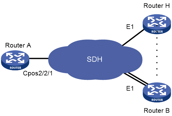
Network configuration
As shown in Figure 2, branch nodes Router B through Router H are uplinked to the central node Router A through E1 links. Router A aggregates these E1 links by using a CPOS interface.
Add one additional E1 link on Router B to expand its capacity, and use an MP-group interface to bind the two E1 links.
Procedure
|
|
IMPORTANT: For correct network synchronization, make sure the master clock mode is configured on the SONET/SDH devices connected to the routers. |
1. Configure Router A:
# Configure E1 channels 1 and 2 of CPOS 2/2/1 to operate in unframed mode.
<RouterA> system-view
[RouterA] controller cpos 2/2/1
[RouterA-Cpos2/2/1] e1 1 unframed
[RouterA-Cpos2/2/1] e1 2 unframed
# Create MP-group 1 and assign an IP address to it.
[RouterA] interface mp-group 1
[RouterA-Mp-group1] ip address 10.1.1.1 24
[RouterA-Mp-group1] quit
# Assign Serial 2/2/1/1:0 and Serial 2/2/1/2:0 to MP-group 1.
[RouterA] interface serial2/2/1/1:0
[RouterA-Serial2/2/1/1:0] ppp mp mp-group 1
[RouterA-Serial2/2/1/1:0] quit
[RouterA] interface serial2/2/1/2:0
[RouterA-Serial2/2/1/2:0] ppp mp mp-group 1
[RouterA-Serial2/2/1/2:0] quit
2. Configure Router B:
# Configure E1 interfaces to operate in E1 mode.
<RouterB> system-view
[RouterB] controller e1 2/4/1
[RouterB-E1 2/4/1] using e1
[RouterB-E1 2/4/1] quit
[RouterB] controller e1 2/4/2
[RouterB-E1 2/4/2] using e1
[RouterB-E1 2/4/2] quit
# Create MP-group 1 and assign an IP address to it.
[RouterB] interface mp-group 1
[RouterB-Mp-group1] ip address 10.1.1.2 24
[RouterB-Mp-group1] quit
# Assign Serial 2/4/1:0 and Serial 2/4/2:0 to MP-group 1.
[RouterB] interface serial2/4/1:0
[RouterB-Serial2/4/1:0] ppp mp mp-group 1
[RouterB-Serial2/4/1:0] quit
[RouterB] interface serial2/4/2:0
[RouterB-Serial2/4/2:0] ppp mp mp-group 1
[RouterB-Serial2/4/2:0] quit
Verifying the configuration
# Verify the serial interface configuration and state, for example, on Router B.
<RouterB> display interface serial 2/4/1:0
# Verify the MP interface, and MP bundle configuration and state, for example, on Router B.
<RouterB> display interface mp-group 1
<RouterB> display interface display ppp mp
# Verify that the routers can ping one another. (Details not shown.)
Troubleshooting CPOS interfaces
Loop and link layer protocol down state detected on serial interfaces created for E1 channels on the CPOS interface
Symptom
The H3C router is connected to another vendor's router through E1 channels on CPOS interfaces across an SDH network. PPP is used on the serial interface created for the E1 channel set.
The output from the display interface serial command shows the following errors:
· The physical state of the serial interface is up, but the link protocol is down.
· The serial interface is in a looped condition.
Solution
The symptom might occur when the router and its directly connected SDH device have different multiplex paths for the E1 channels. Multiplex path inconsistency can cause PPP negotiation failure because the SDH device transmits signals from the router in incorrect timeslots to the remote end. If the SDH device incorrectly maps a signal to an idle timeslot in a looped condition, the router can detect a loop on the serial interface.
To resolve the problem:
1. Identify the multiplex path for the E1 channels on the router.
<Sysname> display controller cpos e1
2. Verify that the router and its directly connected SDH device have the same multiplex path for E1 channels. (Details not shown.)
3. Debug the loop condition.
<Sysname> debugging ppp lcp error
4. If the problem persists, contact H3C Support.
