- Table of Contents
- Related Documents
-
| Title | Size | Download |
|---|---|---|
| 04-POS interface configuration | 141.35 KB |
Contents
Configuring a standard POS interface
Configuring basic settings of a standard POS interface
Enabling dampening on a POS interface
Configuring B1/B2/B3 alarms for standard POS interfaces
Configuring a POS subinterface
Configuring common POS interface settings
Enabling payload scrambling on a POS interface
Configuring the keepalive interval and the keepalive retry limit on a POS interface
Configuring overhead byte on a POS interface
Configuring the statistics polling interval
Configuring the MTU for an interface
Restoring the default settings for an interface
Display and maintenance commands for POS interfaces
POS interface configuration examples
Example: Directly connecting routers through POS interfaces
Example: Connecting routers through POS interfaces across a Frame Relay network
Troubleshooting POS interfaces
Configuring POS interfaces
Commands in this chapter are supported only when the device has related interfaces. For the interfaces that the device has, see the installation guide and interface module manuals.
This chapter describes how to configure physical parameters for standard POS interfaces and POS subinterfaces.
About POS interfaces
Packet over SONET/SDH (POS) is a technology widely used on WAN and MAN. It supports data packets such as IP packets.
SONET and SDH
Synchronous Optical Network (SONET) adopts optical transmission. It is a synchronous transmission system defined by the ANSI and is an international standard transmission protocol.
ITU-T Synchronous Digital Hierarchy (SDH) uses a SONET rate subset. SDH adopts synchronous multiplexing and a flexible mapping structure. It can add or drop low-speed tributary signals to or from SDH signals without a large number of multiplexing/demultiplexing devices. This reduces signal attenuation and decreases device investments.
POS
POS maps length-variable packets directly to SONET synchronous payloads and uses the SONET physical layer transmission standard. It offers high-speed, reliable, and point-to-point data connectivity.
The POS interfaces on the device support PPP, Frame Relay, and HDLC at the data link layer and IP at the network layer. The transmission rate of POS interfaces can be STM-1, STM-4, and STM-16. The rate of a level is four times the nearest lower level.
Configuring a standard POS interface
Restrictions and guidelines
If no cable is connected to the interface, shut down the interface to prevent interface exceptions.
Configuring basic settings of a standard POS interface
1. Enter system view.
system-view
2. Enter standard POS interface view.
interface pos interface-number
3. (Optional.) Configure the interface description.
description text
By default, the description of a POS interface is interface name Interface.
4. Set the CRC length.
crc { 16 | 32 }
The default setting is 32 bits.
The CRC length must be the same at both ends.
5. Set the clock mode.
clock { master | slave }
The default setting is slave.
If the standard POS interface is connected to another router, set its clock mode to be different from the mode used by the remote end. If the standard POS interface is connected to a SONET/SDH device, which provides higher clock precision, always set its clock mode to slave.
6. Set the framing format.
frame-format { sdh | sonet }
The default setting is SDH.
7. Set the data link layer protocol.
link-protocol { fr | hdlc | ppp }
The default setting is PPP.
8. (Optional.) Configure the expected bandwidth of the interface.
bandwidth bandwidth-value
By default, the expected bandwidth (in kbps) is the interface baud rate divided by 1000.
The expected bandwidth is an informational parameter used only by higher-layer protocols for calculation. You cannot adjust the actual bandwidth of an interface by using this command.
9. Bring up the interface.
undo shutdown
By default, a standard POS interface is up.
Enabling dampening on a POS interface
About this task
The interface dampening feature uses an exponential decay mechanism to prevent excessive interface flapping events from adversely affecting routing protocols and routing tables in the network. Suppressing interface state change events protects the system resources. For more information about the interface dampening feature, see "Configuring Ethernet interfaces."
Procedure
1. Enter system view.
system-view
2. Enter standard POS interface view.
interface pos interface-number
3. Enable interface dampening on the interface.
dampening [ half-life reuse suppress max-suppress-time ]
By default, interface dampening is disabled on POS interfaces.
Configuring B1/B2/B3 alarms for standard POS interfaces
About this task
B1, B2, and B3 bytes indicate the signal transmission performance of a line at different levels.
· B1 alarm occurs if the bit error rate of a complete STM-N frame exceeds the B1 alarm threshold.
· B2 alarm occurs if the bit error rate of an STM-1 frame exceeds the B2 alarm threshold.
· B3 alarm occurs if the bit error rate of a multiplexed signal (VC3 or VC4 frame) in the STM-1 frame exceeds the B3 alarm threshold.
To generate SNMP notifications about these alarms, you must set the alarm thresholds and enable the notifications. For more information about SNMP notifications, see Network Management and Monitoring Configuration Guide.
Procedure
1. Enter system view.
system-view
2. Enter standard POS interface view.
interface pos interface-number
3. Enable the SNMP notification about the B1, B2, or B3 alarm.
snmp-agent trap enable { b1-tca | b2-tca | b3-tca }
By default, SNMP notifications about B1, B2, and B3 alarms are enabled on a standard POS interface.
Configuring a POS subinterface
Restrictions and guidelines
You can create POS subinterfaces only on Frame Relay-enabled standard POS interfaces.
Procedure
1. Enter system view.
system-view
2. Create a POS subinterface and enter its view.
interface pos interface-number.subnumber [ p2mp | p2p ]
3. Configure the subinterface description.
description text
By default, the description of a POS subinterface is interface name Interface.
4. Configure the expected bandwidth of the subinterface.
bandwidth bandwidth-value
By default, the expected bandwidth (in kbps) is the interface baud rate divided by 1000.
The expected bandwidth is an informational parameter used only by higher-layer protocols for calculation. You cannot adjust the actual bandwidth of a subinterface by using this command.
5. Bring up the interface.
undo shutdown
By default, a POS subinterface is up.
Configuring common POS interface settings
Enabling payload scrambling on a POS interface
About this task
Payload scrambling enables an interface to scramble outgoing data and descramble incoming data. By preventing the presence of long strings of all 1s or all 0s, payload scrambling enables the receiving end to extract the line clock signal correctly.
If payload scrambling is disabled, the interface does not scramble outgoing data or descramble incoming data.
Restrictions and guidelines
The payload scrambling setting must be the same at both ends of a link to ensure correct communication.
For H3C devices, changing the payload scrambling setting does not affect cell headers. After you change the payload scrambling settings on both ends of a link, verify that the C2 byte value on them match each other. If the two values do not match, use the flag c2 command to modify the C2 byte value on the H3C device.
Procedure
1. Enter system view.
system-view
2. Enter POS interface view.
interface pos interface-number
3. Enable payload scrambling.
scramble
By default, payload scrambling is enabled.
Configuring the keepalive interval and the keepalive retry limit on a POS interface
About this task
On an interface encapsulated with PPP, FR, MFR, or HDLC, the data link layer sends keepalive packets at keepalive intervals to detect the availability of the remote end. The data link layer determines that the peer end is down if it does not receive a response after the keepalive retry limit is reached. The data link layer then reports the link down event to the upper-layer protocols.
Procedure
1. Enter system view.
system-view
2. Enter POS interface view.
interface pos interface-number
3. Set the keepalive interval.
timer-hold seconds
The default setting is 10 seconds.
4. Set the keepalive retry limit.
timer-hold retry retries
The default setting is 5.
Configuring overhead byte on a POS interface
About this task
J0 byte is a section overhead byte. SDH and SONET use this byte to test continuity of the connection between two interfaces at the section level.
J1 byte is a higher-order path overhead byte. SDH and SONET use this byte to test continuity of the connection between two interfaces at the path level.
The C2 byte is a higher-order path overhead byte. It indicates the multiplex structure of virtual container (VC) frames and the property of payload.
Restrictions and guidelines
When the C2 byte of one end is set to 1, the C2 byte of the other end can be set to any character in hexadecimal notation. If the C2 byte of either ends of a link is not set to 1, the C2 byte must be the same at both ends.
The J1 byte must be the same at both ends of a link.
The J0 byte can be different on devices of the same service provider. On the interfaces between two service providers, the J0 byte must be the same.
Procedure
1. Enter system view.
system-view
2. Enter POS interface view.
interface pos interface-number
3. Configure the C2 path signal label byte.
flag c2 flag-value
By default, the C2 byte is 16 in hexadecimal notation.
4. Configure the J0 regenerator section trace byte.
flag j0 { sdh | sonet } flag-value
By default, the system uses the SDH framing format, and the J0 byte value is null in SDH frames.
5. Configure the J1 path trace byte.
flag j1 { sdh | sonet } flag-value
By default, the system uses the SDH framing format, and the J1 byte value is null in SDH frames.
Configuring the statistics polling interval
About this task
Use this feature to set the statistics polling interval for an interface.
To display information about POS interfaces collected in the last statistics polling interval, use the display interface pos command.
To clear interface statistics, use the reset counters interface pos command.
Restrictions and guidelines
A short global statistics polling interval might decrease the system performance and result in inaccurate statistics.
The statistics polling interval configured in system view takes effect on all interfaces.
Configuring the statistics polling interval in system view
1. Enter system view.
system-view
2. Configure the statistics polling interval.
flow-interval interval
By default, the statistics polling interval is 300 seconds.
Configuring the MTU for an interface
Restrictions and guidelines
The MTU setting affects the assembly and fragmentation of IP packets.
After configuring the MTU for an interface, you must use the shutdown command and then the undo shutdown command on the interface for the modification to take effect.
Procedure
1. Enter system view.
system-view
2. Enter POS interface or POS subinterface view.
interface pos { interface-number | interface-number.subnumber [ p2mp | p2p ] }
3. Set the MTU.
mtu size
By default, the MTU of an interface is 1500 bytes.
4. Shut down the interface.
shutdown
5. Bring up the interface.
undo shutdown
Restoring the default settings for an interface
Restrictions and guidelines
|
|
CAUTION: This feature might interrupt ongoing network services. Make sure you are fully aware of the impact of this feature when you use it on a live network. |
This feature might fail to restore the default settings for some commands because of command dependencies or system restrictions. You can use the display this command in interface view to check for these commands and perform their undo forms or follow the command reference to restore their default settings. If your restoration attempt still fails, follow the error message to resolve the problem.
Procedure
1. Enter system view.
system-view
2. Enter POS interface view or POS subinterface view.
interface pos { interface-number | interface-number.subnumber [ p2mp | p2p ] }
3. Restore the default settings for the interface.
default
Display and maintenance commands for POS interfaces
Execute display commands in any view and reset commands in user view.
|
Command |
|
|
Display information about POS interfaces. |
display interface [ pos [ interface-number | interface-number.subnumber ] ] [ brief [ description | down ] ] |
|
Clear statistics for POS interfaces. |
reset counters interface [ pos [ interface-number | interface-number.subnumber ] ] |
POS interface configuration examples
Example: Directly connecting routers through POS interfaces
Network configuration
As shown in Figure 1, connect the routers through POS interfaces.

Procedure
1. Configure Router A:
# Assign an IP address to POS 2/2/1.
<RouterA> system-view
[RouterA] interface pos 2/2/1
[RouterA-Pos2/2/1] ip address 10.110.1.10 255.255.255.0
# Configure the data link layer protocol of the interface.
[RouterA-Pos2/2/1] link-protocol ppp
# Set the MTU to 1500 bytes for the interface.
[RouterA-Pos2/2/1] mtu 1500
# Shut down, and then bring up the interface for the settings to take effect.
[RouterA-Pos2/2/1] shutdown
[RouterA-Pos2/2/1] undo shutdown
[RouterA-Pos2/2/1] quit
2. Configure Router B:
# Set the clock mode to master on POS 2/2/1.
<RouterB> system-view
[RouterB] interface pos 2/2/1
[RouterB-Pos2/2/1] clock master
# Assign an IP address to the interface.
[RouterB-Pos2/2/1] ip address 10.110.1.11 255.255.255.0
# Configure the data link layer protocol of the interface.
[RouterB-Pos2/2/1] link-protocol ppp
# Set the MTU to 1500 bytes for the interface.
[RouterB-Pos2/2/1] mtu 1500
# Shut down, and then bring up the interface for the settings to take effect.
[RouterB-Pos2/2/1] shutdown
[RouterB-Pos2/2/1] undo shutdown
[RouterB-Pos2/2/1] quit
Verifying the configuration
# Display brief information about the POS interfaces on Router A.
[RouterA] display interface pos brief
Brief information on interfaces in route mode:
Link: ADM - administratively down; Stby - standby
Protocol: (s) - spoofing
Interface Link Protocol Primary IP Description
Pos2/2/1 UP UP 10.110.1.10
The output shows that both the physical state and the link layer protocol state of POS 2/2/1 on Router A are up.
# Display brief information about the POS interfaces on Router B.
[RouterB] display interface pos brief
Brief information on interfaces in route mode:
Link: ADM - administratively down; Stby - standby
Protocol: (s) - spoofing
Interface Link Protocol Primary IP Description
Pos2/2/1 UP UP 10.110.1.11
The output shows that both the physical state and the link layer protocol state of POS 2/2/1 on Router B are up.
# Ping Router B from Router A.
[RouterA] ping 10.110.1.11
Ping 10.110.1.11 (10.110.1.11): 56 data bytes, press CTRL+C to break
56 bytes from 10.110.1.11: icmp_seq=0 ttl=255 time=0.127 ms
56 bytes from 10.110.1.11: icmp_seq=1 ttl=255 time=0.091 ms
56 bytes from 10.110.1.11: icmp_seq=2 ttl=255 time=0.072 ms
56 bytes from 10.110.1.11: icmp_seq=3 ttl=255 time=0.074 ms
56 bytes from 10.110.1.11: icmp_seq=4 ttl=255 time=0.079 ms
--- Ping statistics for 10.110.1.11 ---
5 packet(s) transmitted, 5 packet(s) received, 0.0% packet loss
round-trip min/avg/max/std-dev = 0.072/0.089/0.127/0.020 ms
The output shows that Router A and Router B can reach each other through the POS interfaces.
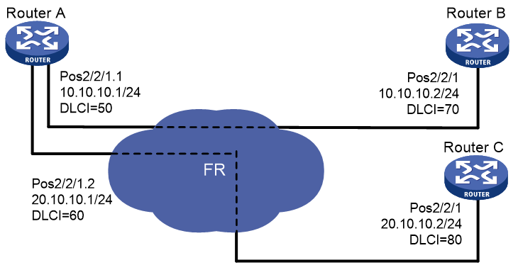
Example: Connecting routers through POS interfaces across a Frame Relay network
Network configuration
As shown in Figure 2, use POS subinterfaces to connect Router A to Router B and Router C across a Frame Relay network. The routers are all DTEs on the Frame Relay network.
Procedure
1. Configure Router A:
# Set the clock mode to slave on POS 2/2/1.
<RouterA> system-view
[RouterA] interface pos 2/2/1
[RouterA-Pos2/2/1] clock slave
# Enable Frame Relay on POS 2/2/1.
[RouterA-Pos2/2/1] link-protocol fr
# Configure POS 2/2/1 as DTE.
[RouterA-Pos2/2/1] fr interface-type dte
[RouterA-Pos2/2/1] quit
# Create subinterface 1 on POS 2/2/1 and assign an IP address to it.
[RouterA] interface pos 2/2/1.1
[RouterA-Pos2/2/1.1] ip address 10.10.10.1 255.255.255.0
# Assign a virtual circuit with DLCI 50 to subinterface 1.
[RouterA-Pos2/2/1.1] fr dlci 50
[RouterA-Pos2/2/1.1-fr-dlci-50] quit
# Map DLCI 50 to the peer IP address 10.10.10.2.
[RouterA-Pos2/2/1.1] fr map ip 10.10.10.2 50
# Set the MTU to 1500 for subinterface 1.
[RouterA-Pos2/2/1.1] mtu 1500
[RouterA-Pos2/2/1.1] quit
# Create subinterface 2 on POS 2/2/1 and assign an IP address to it.
[RouterA] interface pos 2/2/1.2
[RouterA-Pos2/2/1.2] ip address 20.10.10.1 255.255.255.0
# Assign a virtual circuit with DLCI 60 to subinterface 2.
[RouterA-Pos2/2/1.2] fr dlci 60
[RouterA-Pos2/2/1.2-fr-dlci-60] quit
# Map DLCI 60 to the peer IP address 20.10.10.2.
[RouterA-Pos2/2/1.2] fr map ip 20.10.10.2 60
# Set the MTU to 1500 for subinterface 2.
[RouterA-Pos2/2/1.2] mtu 1500
[RouterA-Pos2/2/1.2] quit
2. Configure Router B:
# Set the clock mode to slave on POS 2/2/1.
[RouterB] interface pos 2/2/1
[RouterB-Pos2/2/1] clock slave
# Enable Frame Relay on POS 2/2/1.
[RouterB-Pos2/2/1] link-protocol fr
# Configure POS 2/2/1 as DTE.
[RouterB-Pos2/2/1] fr interface-type dte
# Assign an IP address to POS 2/2/1.
[RouterB-Pos2/2/1] ip address 10.10.10.2 255.255.255.0
# Assign a virtual circuit with DLCI 70 to POS 2/2/1.
[RouterB-Pos2/2/1] fr dlci 70
[RouterB-Pos2/2/1-fr-dlci-70] quit
# Map DLCI 70 to the peer IP address 10.10.10.1.
[RouterB-Pos2/2/1] fr map ip 10.10.10.1 70
# Set the MTU to 1500 for POS 2/2/1.
[RouterB-Pos2/2/1] mtu 1500
[RouterB-Pos2/2/1] quit
3. Configure Router C in the same way Router B is configured. (Details not shown.)
Verifying the configuration
# Display brief information about the POS interfaces on Router A.
[RouterA] display interface pos brief
Brief information on interfaces in route mode:
Link: ADM - administratively down; Stby - standby
Protocol: (s) - spoofing
Interface Link Protocol Primary IP Description
Pos2/2/1.1 UP UP 10.10.10.1
Pos2/2/1.2 UP UP 20.10.10.1
The output shows that both the physical state and the link layer protocol state of POS 2/2/1.1 and POS 2/2/1.2 on Router A are up.
# Display brief information about the POS interfaces on Router B.
[RouterB] display interface pos brief
Brief information on interfaces in route mode:
Link: ADM - administratively down; Stby - standby
Protocol: (s) - spoofing
Interface Link Protocol Primary IP Description
Pos2/2/1.1 UP UP 10.10.10.2
Pos2/2/1.2 UP UP 20.10.10.2
The output shows that both the physical state and the link layer protocol state of POS 2/2/1.1 and POS 2/2/1.2 on Router B are up.
# Ping Router B from Router A.
[RouterA] ping 10.10.10.2
Ping 10.10.10.2 (10.10.10.2): 56 data bytes, press CTRL+C to break
56 bytes from 10.10.10.2: icmp_seq=0 ttl=255 time=0.127 ms
56 bytes from 10.10.10.2: icmp_seq=1 ttl=255 time=0.091 ms
56 bytes from 10.10.10.2: icmp_seq=2 ttl=255 time=0.072 ms
56 bytes from 10.10.10.2: icmp_seq=3 ttl=255 time=0.074 ms
56 bytes from 10.10.10.2: icmp_seq=4 ttl=255 time=0.079 ms
--- Ping statistics for 10.10.10.2 ---
5 packet(s) transmitted, 5 packet(s) received, 0.0% packet loss
round-trip min/avg/max/std-dev = 0.072/0.089/0.127/0.020 ms
The output shows that Router A and Router B can reach each other.
# Ping Router C from Router A.
[RouterA] ping 20.10.10.2
Ping 20.10.10.2 (20.10.10.2): 56 data bytes, press CTRL+C to break
56 bytes from 20.10.10.2: icmp_seq=0 ttl=255 time=0.127 ms
56 bytes from 20.10.10.2: icmp_seq=1 ttl=255 time=0.091 ms
56 bytes from 20.10.10.2: icmp_seq=2 ttl=255 time=0.072 ms
56 bytes from 20.10.10.2: icmp_seq=3 ttl=255 time=0.074 ms
56 bytes from 20.10.10.2: icmp_seq=4 ttl=255 time=0.079 ms
--- Ping statistics for 20.10.10.2 ---
5 packet(s) transmitted, 5 packet(s) received, 0.0% packet loss
round-trip min/avg/max/std-dev = 0.072/0.089/0.127/0.020 ms
The output shows that Router A and Router C can reach each other.
Troubleshooting POS interfaces
Interface physically down
Symptom
The physical state of the POS interface is down.
Solution
To resolve the problem:
1. Verify that the POS interface is connected correctly to the remote port.
¡ The transmit connector at one end must be connected to the receive connector at the other end.
¡ The transmit and receive connectors of the POS interface are not connected by the same fiber. If they are connected by the same fiber, the display interface command displays the "loopback detected" message, whether or not the loopback detection feature is enabled.
2. If the two POS interfaces are directly connected, verify that the two ends use different clock mode settings.
3. If the problem persists, contact H3C Support.
Data link layer down
Symptom
The physical layer is up, but the data link layer is down.
Solution
To resolve the problem:
1. Verify that the two ends have matching clock mode, scrambling setting, and physical parameters.
2. Verify that the two ends have the same data link layer protocol.
3. If the problem persists, contact H3C Support.
Packet loss
Symptom
A large number of IP packets are dropped.
Solution
To resolve the problem:
1. Verify that the correct clock mode is configured on the POS interface.
Incorrect clock mode setting can incur a large number of CRC errors.
2. Verify that the two ends have the same MTU setting.
3. If the problem persists, contact H3C Support.
