- Table of Contents
-
- 12-High Availability Configuration Guide
- 00-Preface
- 01-Load balancing configuration
- 02-Interface backup configuration
- 03-DLDP configuration
- 04-Monitor Link configuration
- 05-VRRP configuration
- 06-Error code detection configuration
- 07-Reth interface and redundancy group configuration
- 08-BFD configuration
- 09-Process placement configuration
- 10-Track configuration
- 11-Interface collaboration configuration
- Related Documents
-
| Title | Size | Download |
|---|---|---|
| 11-Interface collaboration configuration | 109.33 KB |
Contents
Configuring interface collaboration
How interface collaboration works
Interface collaboration tasks at a glance
Prerequisites for interface collaboration
Creating a collaboration group
Configuring collaboration group member interfaces
Configuring a collaboration group member interface in collaboration group view
Configuring a collaboration group member interface in interface view
Configuring the delay for the member interfaces in a collaboration group to come up
Removing ineffective member interfaces from all collaboration groups
Display and maintenance commands for interface collaboration
Interface collaboration configuration examples
Example: Configuring interface collaboration for Layer 3 interfaces
Configuring interface collaboration
About interface collaboration
The interface collaboration feature assigns different interfaces on a device to a collaboration group and associates the states of these interfaces. All member interfaces in a collaboration group can or cannot transmit packets at the same time. This feature is typically used to associate the states of downlink and uplink interfaces.
Typical application
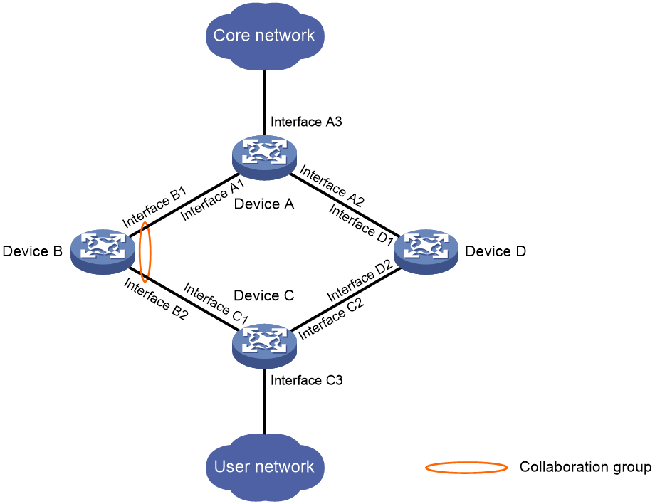
As shown in Figure 1, Device C accesses the core network through Device B. When Interface B1 goes down, the switchover of traffic from Device C to Device D is slow because Interface B2 is still up.
If Interface B1 and Interface B2 belong to one collaboration group, Device B brings down Interface B2 when Interface B1 goes down to achieve fast traffic switchover. Similarly, the device brings down Interface B1 when Interface B2 goes down.
Figure 1 Interface collaboration application scenario
How interface collaboration works
The interface collaboration feature works as follows:
· When any member interface in a collaboration group goes down, the device sets all other member interfaces in the collaboration group to the Collaboration-down state. The state of the collaboration group is down, and no member interfaces in the collaboration group can transmit packets.
· When any member interface in DOWN or Collaboration-down state comes up, the device attempts to bring up all other member interfaces in the collaboration group.
¡ If all other member interfaces come up in 10 seconds, the collaboration group comes up. All member interfaces in the collaboration group can transmit packets.
¡ If any member interface cannot come up in 10 seconds, the device sets that member interface to DOWN state and sets all other member interfaces to the Collaboration-down state. The collaboration group goes down, and no member interfaces in the collaboration group can transmit packets.
Interface collaboration tasks at a glance
To configure interface collaboration, perform the following tasks:
· Creating a collaboration group
· Configuring collaboration group member interfaces
· (Optional.) Configuring the delay for the member interfaces in a collaboration group
· (Optional.) Removing ineffective member interfaces from all collaboration groups
Prerequisites for interface collaboration
Before configuring interface collaboration, you must enable Monitor Link globally (see "Configuring Monitor Link").
Creating a collaboration group
1. Enter system view.
system-view
2. Create a collaboration group and enter collaboration group view.
collaboration-group group-id
By default, no collaboration groups exist.
Configuring collaboration group member interfaces
Restrictions and guidelines
An interface can belong to only one collaboration group.
For a collaboration group to work correctly, do not assign its member interfaces to a redundancy group.
Do not add both Selected ports and Unselected ports in a dynamic aggregation group to the same collaboration group.
If you have configured a member interface as the uplink/downlink interface of a monitor link group, do not configure any other member interface in the same collaboration group as the downlink/uplink interface of any monitor link group.
You can assign only one interface of a link to a collaboration group.
You can configure member interfaces for a collaboration group in collaboration group view or interface view. Configurations made in these views have the same effect.
Configuring a collaboration group member interface in collaboration group view
1. Enter system view.
system-view
2. Enter collaboration group view.
collaboration-group group-id
3. Configure an interface as a member of the collaboration group.
port interface-type interface-number
By default, no member interfaces exist in a collaboration group.
Configuring a collaboration group member interface in interface view
1. Enter system view.
system-view
2. Enter interface view.
interface interface-type interface-number
3. Configure the interface as a member of a collaboration group.
port collaboration-group group-id
By default, an interface is not a collaboration group member.
Configuring the delay for the member interfaces in a collaboration group to come up
About this task
By default, member interfaces in a collaboration group come up and forward service traffic immediately after the device restarts. Traffic loss occurs if the service modules have not returned to normal state.
Perform this task to enable the member interfaces to come up after a configurable delay time upon a device restart.
Procedure
1. Enter system view.
system-view
2. Enter collaboration group view.
collaboration-group group-id
3. Configure the delay for the member interfaces in a collaboration group to come up.
up-delay delay
By default, the delay time is 0 seconds. The member interfaces come up as soon as the device restarts.
Removing ineffective member interfaces from all collaboration groups
About this task
A member interface in a collaboration group becomes ineffective when the number of the interface changes. This task prevents an ineffective interface from causing all other member interfaces in the same collaboration group to go down.
An ineffective interface cannot be automatically assigned to the original collaboration group when its number changed back to the original number. You must assign it to the original collaboration group manually.
Procedure
1. Enter system view.
system-view
2. Enter collaboration group view.
collaboration-group clean
Display and maintenance commands for interface collaboration
Execute the display command in any view:
|
Task |
Command |
|
Display collaboration group information. |
display collaboration-group { group-id | all } [ verbose ] |
Interface collaboration configuration examples
Example: Configuring interface collaboration for Layer 3 interfaces
Network configuration
As shown in Figure 2, configure interface collaboration on Device B. When GigabitEthernet 1/0 on Device B goes down, Device B brings down GigabitEthernet 2/0. When GigabitEthernet 2/0 on Device B goes down, Device B brings down GigabitEthernet 1/0.

Procedure
1. Configure routes to enable Device A and Device C to prefer the route through Device B for forwarding traffic to each other. (This example uses static routes):
# Configure IP addresses for interfaces. (Details not shown.)
# Configure four static routes on Device A.
<DeviceA> system-view
[DeviceA] ip route-static 1.1.5.0 255.255.255.0 1.1.2.2
[DeviceA] ip route-static 1.1.7.0 255.255.255.0 1.1.2.2 preference 50
[DeviceA] ip route-static 1.1.6.0 255.255.255.0 1.1.3.2
[DeviceA] ip route-static 1.1.7.0 255.255.255.0 1.1.3.2 preference 70
# Configure two static routes on Device B.
<DeviceB> system-view
[DeviceB] ip route-static 1.1.4.0 255.255.255.0 1.1.2.1
[DeviceB] ip route-static 1.1.7.0 255.255.255.0 1.1.5.2
# Configure four static routes on Device C.
<DeviceC> system-view
[DeviceC] ip route-static 1.1.2.0 255.255.255.0 1.1.5.1
[DeviceC] ip route-static 1.1.4.0 255.255.255.0 1.1.5.1 preference 50
[DeviceC] ip route-static 1.1.3.0 255.255.255.0 1.1.6.2
[DeviceC] ip route-static 1.1.4.0 255.255.255.0 1.1.6.2 preference 70
# Configure two static routes on Device D.
<DeviceD> system-view
[DeviceD] ip route-static 1.1.4.0 255.255.255.0 1.1.3.1
[DeviceD] ip route-static 1.1.7.0 255.255.255.0 1.1.6.1
2. Configure interface collaboration on Device B:
# Enable Monitor Link globally. By default, Monitor Link is enabled globally.
<DeviceB> system-view
[DeviceB] undo monitor-link disable
# Create collaboration group 1.
[DeviceB] collaboration-group 1
# Assign GigabitEthernet 1/0 and GigabitEthernet 2/0 to collaboration group 1.
[DeviceB-collaboration-group1] port gigabitethernet 1/0
[DeviceB-collaboration-group1] port gigabitethernet 2/0
Verifying the configuration
1. Verify that the state of the uplink interface affects the state of the downlink interface.
# Display the static routing information on Device C.
[DeviceC] display ip routing-table protocol static
Summary count : 3
Static Routing table status : <Active>
Summary count : 3
Destination/Mask Proto Pre Cost NextHop Interface
1.1.2.0/24 Static 60 0 1.1.5.1 GE1/0
1.1.3.0/24 Static 60 0 1.1.6.2 GE2/0
1.1.4.0/24 Static 50 0 1.1.5.1 GE1/0
Static Routing table status : <Inactive>
Summary count : 0
The output shows that the effective route from Device C to Device A goes through Device B.
# Shut down GigabitEthernet 1/0 on Device B, and display information about collaboration group 1.
[DeviceB] display collaboration-group 1 verbose
Collaboration group protocol status: Enabled
Collaboration group 1 information:
Group status : DOWN
Member up delay : 0 seconds
Last up time : 16:55:34 2017/04/05
Last down time : 16:57:22 2017/04/05
Member Status
GE1/0 DOWN
GE2/0 Collaboration-down
The output shows that collaboration group 1 is in DOWN state, GigabitEthernet 1/0 is in DOWN state, and GigabitEthernet 2/0 is in Collaboration-down state.
# Display the static routing information on Device C.
[DeviceC] display ip routing-table protocol static
Summary count : 2
Static Routing table status : <Active>
Summary count : 2
Destination/Mask Proto Pre Cost NextHop Interface
1.1.3.0/24 Static 60 0 1.1.6.2 GE2/0
1.1.4.0/24 Static 70 0 1.1.6.2 GE2/0
Static Routing table status : <Inactive>
Summary count : 0
The output shows that the effective route from Device C to Device A goes through Device D.
2. Verify that the state of the downlink interface affects the state of the uplink interface.
# Display the static routing information on Device A.
[DeviceA] display ip routing-table protocol static
Summary count : 3
Static Routing table status : <Active>
Summary count : 3
Destination/Mask Proto Pre Cost NextHop Interface
1.1.5.0/24 Static 60 0 1.1.2.2 GE1/0
1.1.6.0/24 Static 60 0 1.1.3.2 GE2/0
1.1.7.0/24 Static 50 0 1.1.2.2 GE1/0
Static Routing table status : <Inactive>
Summary count : 0
The output shows that the effective route from Device A to Device C goes through Device B.
# Shut down GigabitEthernet 2/0 on Device B, and display information about collaboration group 1.
[DeviceB] display collaboration-group 1 verbose
Collaboration group protocol status: Enabled
Collaboration group 1 information:
Group status : DOWN
Member up delay : 0 seconds
Last up time : 17:11:47 2017/04/05
Last down time : 17:14:37 2017/04/05
Member Status
GE1/0 Collaboration-down
GE2/0 DOWN
The output shows that collaboration group 1 is in DOWN state, GigabitEthernet 1/0 is in Collaboration-down state, and GigabitEthernet 2/0 is in DOWN state.
# Display the static routing information on Device A.
[DeviceA] display ip routing-table protocol static
Summary count : 2
Static Routing table status : <Active>
Summary count : 2
Destination/Mask Proto Pre Cost NextHop Interface
1.1.6.0/24 Static 60 0 1.1.3.2 GE2/0
1.1.7.0/24 Static 70 0 1.1.3.2 GE2/0
Static Routing table status : <Inactive>
Summary count : 0
The output shows that the effective route from Device A to Device C goes through Device D.
