- Table of Contents
-
- 12-High Availability Configuration Guide
- 00-Preface
- 01-Load balancing configuration
- 02-Interface backup configuration
- 03-DLDP configuration
- 04-Monitor Link configuration
- 05-VRRP configuration
- 06-Error code detection configuration
- 07-Reth interface and redundancy group configuration
- 08-BFD configuration
- 09-Process placement configuration
- 10-Track configuration
- 11-Interface collaboration configuration
- Related Documents
-
| Title | Size | Download |
|---|---|---|
| 08-BFD configuration | 142.97 KB |
Contents
Single-hop detection and multihop detection
Restrictions and guidelines: BFD configuration
Configuring BFD sessions in echo packet mode
Configuring BFD session parameters for single-hop detection
Configuring BFD session parameters for multihop detection
Configuring BFD sessions in control packet mode
Configuring BFD session parameters for single-hop detection
Configuring BFD session parameters for multihop detection
Enabling SNMP notifications for BFD
Display and maintenance commands for BFD
Restrictions and guidelines: SBFD configuration
Configuring BFD
About BFD
Bidirectional forwarding detection (BFD) provides a general-purpose, standard, medium- and protocol-independent fast failure detection mechanism. It can detect and monitor the connectivity of forwarding paths to detect communication failures quickly so that measures can be taken to ensure service continuity and enhance network availability.
BFD can uniformly and quickly detect the failures of the bidirectional forwarding paths between two devices for upper-layer protocols such as routing protocols. The hello mechanism used by upper-layer protocols needs seconds to detect a link failure, while BFD can provide detection measured in milliseconds.
Single-hop detection and multihop detection
BFD can be used for single-hop and multihop detections.
· Single-hop detection—Detects the IP connectivity between two directly connected systems.
· Multihop detection—Detects any of the paths between two systems. These paths have multiple hops, and might overlap.
BFD session modes
BFD sessions use echo packets and control packets.
Echo packet mode
Echo packets are encapsulated into UDP packets with port number 3785.
The local end of the link sends echo packets to establish BFD sessions and monitor link status. The peer end does not establish BFD sessions and only forwards the packets back to the originating end. If the local end does not receive echo packets from the peer end within the detection time, it considers the session to be down.
In echo packet mode, BFD supports multihop detection only for MPLS TE tunnel and VXLAN tunnel scenarios. Both BFD sessions for single-hop detection and BFD sessions for multihop detection are independent of the operating mode.
Control packet mode
Control packets are encapsulated into UDP packets with port number 3784 for single-hop detection or port number 4784 for multihop detection.
The two ends of the link negotiate the establishment of BFD sessions by using the session parameters carried in control packets. Session parameters include session discriminators, desired minimum packet sending and receiving intervals, and local BFD session state.
Before a BFD session is established, BFD has two operating modes—active and passive.
· Active mode—BFD actively sends BFD control packets regardless of whether any BFD control packet is received from the peer.
· Passive mode—BFD does not send control packets until a BFD control packet is received from the peer.
At least one end must operate in active mode for a BFD session to be established.
After a BFD session is established, the two ends can operate in the following BFD operating modes:
· Asynchronous mode—The device periodically sends BFD control packets. The device considers that the session is down if it does not receive any BFD control packets within a specific interval.
· Demand mode—The device periodically sends BFD control packets with the D bit set. If the peer end is operating in Asynchronous mode (default), the peer end stops sending BFD control packets after receiving control packets with the D bit set. In this case, BFD detects only the connectivity from the local end to the peer end. If the peer end does not receive control packets within the detection time, the session is declared down. If the peer end is operating in Demand mode, both ends stop sending BFD control packets. The system uses other mechanisms such as Hello mechanism and hardware detection to detect links. The Demand mode can be used to reduce the overhead when a large number of BFD sessions exist.
Supported features
|
Features |
Reference |
|
Static routing IS-IS OSPF RIP BGP IP fast reroute (FRR) |
Layer 3—IP Routing Configuration Guide |
|
IPv6 static routing OSPFv3 |
Layer 3—IP Routing Configuration Guide |
|
PIM |
IP Multicast Configuration Guide |
|
RSVP MPLS MPLS L3VPN MPLS OAM |
MPLS Configuration Guide |
|
Track |
"Configuring Track" |
|
Ethernet link aggregation |
Layer 2—LAN Switching Configuration Guide |
Protocols and standards
· RFC 5880, Bidirectional Forwarding Detection (BFD)
· RFC 5881, Bidirectional Forwarding Detection (BFD) for IPv4 and IPv6 (Single Hop)
· RFC 5882, Generic Application of Bidirectional Forwarding Detection (BFD)
· RFC 5883, Bidirectional Forwarding Detection (BFD) for Multihop Paths
· RFC 5884, Bidirectional Forwarding Detection (BFD) for MPLS Label Switched Paths (LSPs)
· RFC 5885, Bidirectional Forwarding Detection (BFD) for the Pseudowire Virtual Circuit Connectivity Verification (VCCV)
· RFC 7130, Bidirectional Forwarding Detection (BFD) on Link Aggregation Group (LAG) Interfaces
Restrictions and guidelines: BFD configuration
· By default, the device runs BFD version 1 and is compatible with BFD version 0. You cannot change the BFD version to 0 through commands. When the peer device runs BFD version 0, the local device automatically switches to BFD version 0.
· After a BFD session is established, the two ends negotiate BFD parameters, including minimum sending interval, minimum receiving interval, initialization mode, and packet authentication, by exchanging negotiation packets. They use the negotiated parameters without affecting the session status.
· BFD session flapping might occur on an aggregate interface with member ports on different IRF member devices. When the master device, which receives and sends BFD packets, is removed or restarted, a subordinate device might not immediately take over. For example, a subordinate device will not take over when the subordinate device has a short detection time or a large number of BFD sessions. (In IRF mode.)
Configuring BFD sessions in echo packet mode
About this task
A static BFD session can be created manually by using the bfd static command or created dynamically when an application module collaborates with BFD.
Restrictions and guidelines
If you also configure uRPF on the device, follow these restrictions and guidelines:
· For the collaboration between an application module and a BFD session in echo packet mode, use an ACL for uRPF to permit echo packets from the peer device. Without the ACL configuration, uRPF will drop these echo packets.
· For a static BFD session, make sure the source IPv4/IPv6 address specified in the session can pass the uRPF check. If the source IPv4/IPv6 address cannot pass the check, uRPF will drop the echo packets from the peer device.
For more information about uRPF, see Security Configuration Guide.
Creating a static BFD session
About this task
A static BFD session in echo packet mode can be used to perform single-hop detection and multihop detection.
Restrictions and guidelines
You need to create a static BFD session in echo packet mode on only the local device to perform detection.
When creating a static BFD session, you must specify a peer IPv4 or IPv6 address. The system checks only the format of the IP address but not its correctness. If the peer IPv4 or IPv6 address is incorrect, the static BFD session cannot be established.
Different static BFD sessions cannot have the same local discriminator.
As a best practice, specify the source IP address for echo packets when creating a static BFD session. If you do not specify the source IP address, the device uses the IP address specified in the bfd echo-source-ip or bfd echo-source-ipv6 command as the source IP address of echo packets.
Creating a static BFD session for single-hop detection
1. Enter system view.
system-view
2. Configure the source IP address of echo packets.
¡ Configure the source IP address of echo packets.
bfd echo-source-ip ip-address
By default, no source IPv4 address is configured for echo packets.
As a best practice, do not configure the source IPv4 address to be on the same network segment as any local interface's IPv4 address. If you configure such a source IPv4 address, a large number of ICMP redirect packets might be sent from the peer, resulting in link congestion.
¡ Configure the source IPv6 address of echo packets.
bfd echo-source-ipv6 ipv6-address
By default, no source IPv6 address is configured for echo packets.
The source IPv6 address of echo packets can only be a global unicast address.
3. Create a static BFD session and enter static BFD session view.
IPv4:
bfd static session-name [ peer-ip ipv4-address interface interface-type interface-number destination-ip ipv4-address [ source-ip ipv4-address ] one-arm-echo discriminator { local local-value | auto } ]
IPv6:
bfd static session-name [ peer-ipv6 ipv6-address interface interface-type interface-number destination-ipv6 ipv6-address [ source-ipv6 ipv6-address ] one-arm-echo discriminator { local local-value | auto } ]
Creating a static BFD session for multihop detection
1. Enter system view.
system-view
2. Configure the source IP address of echo packets.
¡ Configure the source IP address of echo packets.
bfd echo-source-ip ip-address
By default, no source IPv4 address is configured for echo packets.
As a best practice, do not configure the source IPv4 address to be on the same network segment as any local interface's IPv4 address. If you configure such a source IPv4 address, a large number of ICMP redirect packets might be sent from the peer, resulting in link congestion.
¡ Configure the source IPv6 address of echo packets.
bfd echo-source-ipv6 ipv6-address
By default, no source IPv6 address is configured for echo packets.
The source IPv6 address of echo packets can only be a global unicast address.
3. Create a static BFD session and enter static BFD session view.
IPv4:
bfd static session-name [ peer-ip ipv4-address [ vpn-instance vpn-instance-name ] destination-ip ipv4-address [ source-ip ipv4-address ] one-arm-echo discriminator { local local-value | auto } ]
IPv6:
bfd static session-name [ peer-ipv6 ipv6-address [ vpn-instance vpn-instance-name ] destination-ipv6 ipv6-address [ source-ipv6 ipv6-address ] one-arm-echo discriminator { local local-value | auto } ]
Configuring BFD session parameters for single-hop detection
1. Enter system view.
system-view
2. Enter interface view.
interface interface-type interface-number
3. Set the minimum interval for receiving BFD echo packets.
bfd min-echo-receive-interval interval
The default setting is 500 milliseconds.
4. Set the detection time multiplier.
bfd detect-multiplier value
The default setting is 5.
Configuring BFD session parameters for multihop detection
1. Enter system view.
system-view
2. Set the minimum interval for receiving BFD echo packets.
bfd multi-hop min-echo-receive-interval interval
The default setting is 500 milliseconds.
3. Set the detection time multiplier.
bfd multi-hop detect-multiplier value
The default setting is 5.
Configuring BFD sessions in control packet mode
Restrictions and guidelines
BFD version 0 does not support the following commands:
· bfd session init-mode.
· bfd authentication-mode.
· bfd demand enable.
· bfd echo enable.
Configuring BFD session parameters for single-hop detection
1. Enter system view.
system-view
2. Specify the mode for establishing a BFD session.
bfd session init-mode { active | passive }
By default, active is specified.
1. Enter interface view.
interface interface-type interface-number
2. (Optional.) Configure the authentication mode for single-hop control packets.
bfd authentication-mode{ m-md5 | m-sha1 | md5 | sha1 | simple } key-id { cipher cipher-string | plain plain-string }
By default, single-hop BFD packets are not authenticated.
3. Enable the Demand BFD session mode.
bfd demand enable
By default, the BFD session is in Asynchronous mode.
4. Set the minimum interval for transmitting single-hop BFD control packets.
bfd min-transmit-interval interval
The default setting is 500 milliseconds.
5. Set the minimum interval for receiving single-hop BFD control packets.
bfd min-receive-interval interval
The default setting is 500 milliseconds.
6. Set the single-hop detection time multiplier.
bfd detect-multiplier value
The default setting is 5.
Configuring BFD session parameters for multihop detection
1. Enter system view.
system-view
2. Specify the mode for establishing a BFD session.
bfd session init-mode { active | passive }
By default, active is specified.
3. Configure the authentication mode for multihop BFD control packets.
bfd multi-hop authentication-mode { m-md5 | m-sha1 | md5 | sha1 | simple } key-id { cipher cipher-string | plain plain-string }
By default, no authentication is performed.
4. Configure the destination port number for multihop BFD control packets.
bfd multi-hop destination-port port-number
The default setting is 4784.
5. Set the multihop detection time multiplier.
bfd multi-hop detect-multiplier value
The default setting is 5.
6. Set the minimum interval for receiving multihop BFD control packets.
bfd multi-hop min-receive-interval interval
The default setting is 500 milliseconds.
7. Set the minimum interval for transmitting multihop BFD control packets.
bfd multi-hop min-transmit-interval interval
The default setting is 500 milliseconds.
8. (Optional.) Set the delay timer for BFD to notify upper-layer protocols of session establishment failures.
bfd init-fail-timer seconds
By default, BFD does not notify upper-layer protocols of session establishment failures.
|
|
CAUTION: For session establishment failures caused by configuration mismatches at the two ends, this command can cause the upper-layer protocol to act incorrectly. Therefore, use this command with caution. BFD status mismatch and BFD authentication configuration mismatch are examples of configuration mismatches. |
Enabling the echo function
About this task
This function enables the local system to periodically send echo packets to the remote system. The remote system loops back the echo packets to the local system without processing them. If the local system does not receive the looped-back echo packets, it declares the BFD session down.
This function is supported only for single-hop detection.
Restrictions and guidelines
This function does not take effect on BFD sessions associated with interface states.
Procedure
1. Enter system view.
system-view
2. Enter interface view.
interface interface-type interface-number
3. Enable the echo function.
bfd echo [ receive | send ] enable
By default, the echo function is disabled.
Configuring a BFD template
About this task
Perform this task to specify BFD parameters in a template for sessions without next hops. You can configure BFD parameters for LSPs and PWs through a BFD template.
Procedure
1. Enter system view.
system-view
2. Create a BFD template and enter BFD template view.
bfd template template-name
3. (Optional.) Configure the authentication mode for BFD control packets.
bfd authentication-mode{ m-md5 | m-sha1 | md5 | sha1 | simple } key-id { cipher cipher-string | plain plain-string }
By default, no authentication is performed.
4. Set the detection time multiplier.
bfd detect-multiplier value
The default setting is 5.
5. Set the minimum interval for receiving BFD echo packets.
bfd min-echo-receive-interval interval
The default setting is 500 milliseconds.
6. Set the minimum interval for receiving BFD control packets.
bfd min-receive-interval interval
The default setting is 500 milliseconds.
7. Set the minimum interval for transmitting BFD control packets.
bfd min-transmit-interval interval
The default setting is 500 milliseconds.
Enabling SNMP notifications for BFD
About this task
To report critical BFD events to an NMS, enable SNMP notifications for BFD. For BFD event notifications to be sent correctly, you must also configure SNMP as described in Network Management and Monitoring Configuration Guide.
Procedure
1. Enter system view.
system-view
2. Enable SNMP notifications for BFD.
snmp-agent trap enable bfd
By default, SNMP notifications are enabled for BFD.
Display and maintenance commands for BFD
Execute the display command in any view and the reset command in user view.
|
Task |
Command |
|
Display BFD session information. |
display bfd session [ discriminator local local-value | verbose ] |
|
Clear BFD session statistics. |
reset bfd session statistics |
Configuring SBFD
About SBFD
Seamless BFD (SBFD) is a unidirectional failure detection mechanism that simplifies the BFD state machine and shortens the session negotiation time to provide shorter detection time than BFD. A SBFD session has only UP and DOWN states. SBFD is used in scenarios where only one end of a link requires failure detection.
An SBFD session involves the following roles:
· Initiator—Initiates and maintains an SBFD session by periodically sends SBFD control packets.
· Reflector—Listens for incoming SBFD control packets and replies with response SBFD control packets. The reflector does not maintain the SBFD session state.
The SBFD detection mechanism is as follows:
1. The initiator periodically sends SBFD control packets to the reflector.
2. After receiving an SBFD control packet, the reflector checks whether the remote discriminator carried in the packet is the same as the locally configured one. If they are the same, the reflector sends a response SBFD control packet to the initiator. If they are different, the reflector drops the SBFD control packet.
3. If the initiator receives the response SBFD control packet before the detection time expires, it considers the link available. Otherwise, it considers the link unavailable.
Restrictions and guidelines: SBFD configuration
A node can act as the initiator of one session and the reflector of another session at the same time.
An SBFD session can only be established statically. You must manually specify the remote discriminator for an SBFD session.
SBFD tasks at a glance
To configure SBFD, perform the following tasks:
¡ Configuring the initiator for SRv6 TE policy detection
· (Optional.) Configuring a BFD template
Configuring the initiator
Restrictions and guidelines
The remote discriminator in SBFD control packets sent by the initiator must be specified in the sbfd local-discriminator command on the reflector. If the discriminator is not specified on the reflector, the reflector does not reply with response SBFD control packets.
Configuring the initiator for SRv6 TE policy detection
About this task
SBFD can detect the connectivity of an SRv6 TE policy and provides millisecond-level fault detection and fast fault switchover. In an SRv6 TE policy, the candidate path with the greatest preference value acts as the primary path and that with the second greatest preference value acts as the backup path. SBFD detects both primary and backup paths and all SID lists of each path. If all the SID lists for the primary path are faulty, SBFD triggers a primary-to-back path switchover.
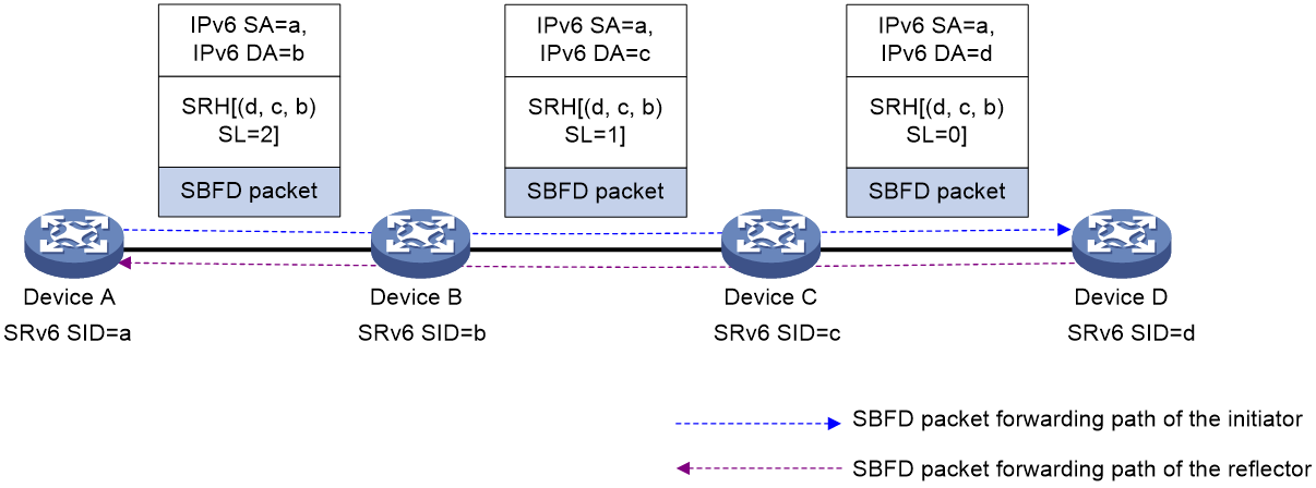
As shown in Figure 1, configure an SRv6 TE policy on Device A and use SBFD to detect the SRv6 TE policy. The detection process is as follows:
1. The source node (Device A, the initiator) sends SBFD control packets that encapsulate the SID lists of the primary and backup candidate paths of the SRv6 TE policy.
2. After the destination node (Device D, the reflector) receives an SBFD control packet, it checks whether the remote discriminator carried the packet is the same as the local discriminator. If they are the same, the reflector sends the response SBFD control packet to the initiator according to the IPv6 routing table. If they are different, the reflector drops the SBFD control packet.
3. If the source node receives the response SBFD control packet before the detection time expires, it considers the corresponding SID list (forwarding path) of the SRv6 TE policy available. Otherwise, the device considers the SID list faulty. If all the SID lists for the primary path are faulty, SBFD triggers a primary-to-back path switchover.
Figure 1 SBFD for SRv6 TE policy procedure
Procedure
1. Enter system view.
system-view
2. (Optional.) Set the detection time multiplier.
bfd multi-hop detect-multiplier value
The default setting is 5.
3. (Optional.) Set the minimum interval for sending SBFD control packets.
bfd multi-hop min-transmit-interval interval
The default setting is 500 milliseconds.
4. Specify the source IPv6 address used by the initiator to send SBFD control packets.
sbfd source-ipv6 ipv6-address
By default, no source IPv6 address is specified for SBFD control packets.
5. Enter SRv6 view.
segment-routing ipv6
6. Enter SRv6 TE view.
traffic-engineering
7. Enter SRv6 TE policy view.
policy policy-name
8. Configure SBFD for the SRv6 TE policy.
srv6-policy sbfd remote remote-id [ template template-name ] [ backup-template backup-template-name ]
By default, SBFD is not configured for an SRv6 TE policy.
For more information about this command, see SRv6 TE policy commands in Segment Routing Command Reference.
Configuring the reflector
Restrictions and guidelines
If you configure an IPv4 address as the local discriminator, the device automatically converts it to an integer. Configure an IPv4 address local discriminator only when it is required for interoperation with a third-party device.
The reflector replies with a response SBFD control packet only when the remote discriminator in the SBFD control packet sent from the initiator is specified in the sbfd local-discriminator command.
Procedure
1. Enter system view.
system-view
2. Configure a local discriminator.
sbfd local-discriminator { ipv4-address | integer-value }
By default, no local discriminator is configured.
You can execute this command multiple times to configure multiple local discriminators.
Configuring a BFD template
About this task
You can flexibly configure BFD parameters through a BFD template.
Procedure
1. Enter system view.
system-view
2. Create a BFD template and enter BFD template view.
bfd template template-name
3. Set the detection time multiplier.
bfd detect-multiplier value
The default setting is 5.
4. Set the minimum interval for sending SBFD control packets.
bfd min-transmit-interval interval
The default setting is 500 milliseconds.
Display and maintenance commands for SBFD
Execute the display command in any view.
|
Task |
Command |
|
Display SBFD session information. |
display sbfd session { initiator | reflector } [ discriminator value | verbose ] |
